integration of domain-specific modeling languages and uml
TRANSCRIPT

International Journal of Computer Science and Applications, ©Technomathematics Research Foundation Vol. 6, No. 5, pp 145-174, 2009
145
INTEGRATION OF DOMAIN-SPECIFIC MODELING LANGUAGES AND UML THROUGH UML PROFILE EXTENSION MECHANISM
GIOVANNI GIACHETTI
Centro de Investigación en Métodos de Producción de Software, Universidad Politécnica de Valencia,
Camino de Vera s/n 46022 Valencia, Spain [email protected]
BEATRIZ MARÍN
Centro de Investigación en Métodos de Producción de Software, Universidad Politécnica de Valencia,
Camino de Vera s/n 46022 Valencia, Spain [email protected]
OSCAR PASTOR
Centro de Investigación en Métodos de Producción de Software, Universidad Politécnica de Valencia,
Camino de Vera s/n 46022 Valencia, Spain [email protected]
A key requirement for MDD solutions is to have a modeling language that allows the correct representation of conceptual models. Nowadays, there are two options that are the most widely used for the definition of these modeling languages: 1) the specification of a domain-specific modeling language (DSML) or 2) the customization of UML. In practice, these two modeling alternatives are viewed as opposite solutions. However, since both alternatives provide benefits for the application of MDD solutions, in this article, we present a proposal that uses UML profile extension mechanisms to interchange modeling information between DSML-based models and UML models. This proposal shows how these two modeling alternatives can be integrated in a unique MDD solution. Keywords: UML profile; DSML; UML; MDD.
1. Introduction
One of the most important concerns when elaborating a Model-Driven Development (MDD) solution [Selic (2003)] is the specification of a modeling language that allows the required software products to be represented at the conceptual level without ambiguity. Among the different choices that exist for the definition of an adequate modeling language, there are two alternatives that appear to be the most suitable. The first of these is the creation of a specific language that is tailor-made for the MDD approach. This language is called Domain-Specific Modeling Language (DSML) [Pohjonen and Kelly (2002)]. The second alternative is the customization of UML by means of extensions defined in the UML metamodel, which represent the abstract syntax related to the

Giovanni Giachetti, Beatriz Marín, and Oscar Pastor 146
semantics required for the MDD proposal [Selic (2007)]. These extensions are defined by means of one of the existent UML extension mechanisms [Bruck and Hussey (2007)].
An analysis of the first modeling alternative indicates that a DSML provides a precise characterization of the conceptual constructs required by MDD approaches. Furthermore, the number of conceptual constructs required by a MDD proposal is generally smaller than the number of conceptual constructs that are defined in the UML Specification [OMG (2007b)]. For this reason, the implementation of specific MDD tools (such as model compilers or documentation tools) is easier to perform for a DSML than for UML. At the same time, the smaller size of a DSML in relation to UML facilitates the implementation of the specific model editors that are required for the definition of DSML-based models. These model editors can provide improved modeling features that are in accordance with the development domain. However, it is important to note that the implementation and maintenance of these specific editors involve an extra effort when putting an MDD approach in practice [Selic (2007)].
The second alternative for the specification of an adequate modeling language is the use of UML, which is a widely known modeling language that has a lot of support tools. However, it is also true that the semantics of certain UML conceptual constructs does not provide enough precision for its application in effective MDD processes. This lack of precision can be easily perceived in the Semantic Extension Points defined in the UML specification [OMG (2007b)], where different semantic representations for one conceptual construct or the lack of definition of the appropriate semantics can be found. An example of this is on of the semantic extension points related to the UML association, which state that “The order and way in which part instances in a composite are created is not defined” [OMG (2007b)].
In order to introduce the required semantic precision into UML, there are different extension mechanisms that can be used [Bruck and Hussey (2007)]. One of them, the UML Profile extension mechanism, is the most suitable extension alternative because it is part of the UML standard and, hence, the extensions defined with a UML profile can be supported by UML-based tools. Therefore, existent MDD technologies based on UML (such as requirement traceability tools or cost estimation tools) can be reused by other MDD solutions that also use UML as base modeling language. In addition the UML profile extension mechanism allows the existent UML editors to be used thereby reducing the costs of implementing specific model editors.
However, since UML is a general purpose modeling language, the modeling facilities that the existent UML editors provide may not be the most appropriate to perform specific modeling tasks related to MDD approaches. Furthermore, the extension capabilities of the UML profile present limitations that in some cases might prevent a correct representation of all the modeling needs that are required by MDD proposals.
After analyzing these two modeling alternatives (UML and DSMLs), an interesting modeling approach would be to provide a hybrid modeling schema that integrates both alternatives. This integration can be obtained by means of the transparent interchange of UML models and DSML models. Thus, it would be possible to take advantage of the existent UML tools for those models that can be represented by means of UML and only

Integration of Domain-Specific Modeling Languages and UML through UML Profile Extension Mechanism
147
to implement specific tools for those models that require more complex modeling capabilities. It would also be possible to implement specific DSML-based tools for those features that are outside of the scope of existent UML tools.
This article presents a proposal to obtain a hybrid modeling schema that integrates UML and DSML models. This proposal is based on the automatic generation of a UML profile from a DSML metamodel. All the information required to interchange DSML models and UML models is obtained from this UML profile generation. Finally the application of this interchange proposal into a specific MDD approach is presented by means of a brief example.
The rest of the article is organized as follows: Section 2 presents the background related to UML profiles and DSMLs. Section 3 introduces our proposal for the UML profile generation process. Section 4 details how the results obtained in the UML profile generation are used for the interchange of models. Section 5 presents how to apply the interchange proposal. Section 6 presents a discussion about the related works, and finally, Section 7 presents our conclusions and further work.
2. Background
This section briefly introduces the aspects that are relevant to the definition of DSMLs and UML profiles. This background is specially focused on those aspects that can be used to perform an interchange between DSML-based models and UML models that are extended with UML profiles.
2.1. Domain-Specific Modeling Languages
A Domain-Specific Modeling Language (DSML) represents the semantics of the constructs required for the definition of the conceptual models involved in a MDD solution. For the construction of a DSML, a common strategy is to define a metamodel to represent the abstract syntax of the required conceptual constructs [Harel, and Rumpe (2004)]. For the elaboration of this DSML Metamodel, one of the most interesting alternatives is the use of the Essential Meta Object Facility (EMOF) standard defined by OMG1. EMOF is an essential set of metamodeling constructs, which is defined within the Meta Object Facility (MOF) specification [OMG (2006a)]. In the context of this work, the use of EMOF, instead of the Complete MOF specification (CMOF or simply MOF), takes special relevance because the metamodeling capabilities provided by EMOF are very close to the extension capabilities that the UML profiles provide. Therefore, by using EMOF, the features of the resultant DSML metamodels can be represented as UML profiles extensions. By contrast, the complete MOF specification provides a set of metamodeling capabilities that can not be expressed as UML profiles extensions. An example of this is that in MOF-based metamodel is possible the redefinition of properties, which is not part of the EMOF specification. In the context of UML extensions [Bruck and Hussey (2007)], the properties redefinition corresponds to a
1 Object Management Group Web site, http://www.omg.org/

Giovanni Giachetti, Beatriz Marín, and Oscar Pastor 148
heavy-weight extension mechanism because implies a change in the extended metamodel: a property of the target metamodel is redefined (changed) by a property of the defined UML extension. However, since the UML profile is a light-weight extension mechanism, it cannot change the extended metamodel, and therefore, the properties defined as UML profile extensions cannot redefine properties that already exist in the target metamodel.
Another benefit of using EMOF is that it has a standardized XMI definition [9].The benefit of using an XMI standardized definition for EMOF metamodels is that it facilitates the interchange and validation of the defined metamodels and support from existent metamodeling tools, such as Eclipse Modeling Framework (EMF) project2, can be obtained. EMF is an Eclipse project that provides an open-source implementation of the EMOF standard, which is called Ecore. In addition, by means of tools like Eclipse GMF3 and Eclipse ATL4, specific model editors and model transformations can be defined over Ecore metamodels.
2.2. UML Profiles
The UML profile extension mechanism is part of the UML specification and it is defined inside of the UML Infrastructure [OMG (2007a)]. It defines the mechanisms used to adapt existing MOF-based metamodels to specific platforms, domains, business objects, or software process modeling. Since this extension mechanism is a part of the UML standard, it can be supported by UML tools. This feature is one of the main advantages of the UML profile over other UML customization mechanisms [Bruck and Hussey (2007)], which are not part of the UML standard and, hence, they are not supported by UML tools.
A UML profile is represented as a UML package that is stereotyped with the tag <<profile>>. It has three main constructs for the definition of the required extensions: stereotypes, tagged values, and OCL rules: • The stereotype is the main construct for the specification of a UML profile. It is a
special kind of UML class (specialization of the metaclass Class from the UML metamodel). Therefore, the semantics and notation of a stereotype is very similar to a UML class. The stereotypes are identified by a unique name, and represent the set of the extensions that are applied over the classes of the extended metamodel. The extended classes are identified by means of extensions relationships that go from the stereotypes to the metaclasses that they extend. For the definition of the extensions that the stereotypes perform, the tagged values and the OCL rules are used.
• A tagged value is a property (specialization of the UML metaclass Property) that is owned by a stereotype. A tagged value represents a new property that is added to the metaclass extended by the stereotype that owns the tagged value. According to the last UML specification, the type of the tagged values can be specified from other classes or stereotypes. Therefore, the tagged values can be used for the definition of
2 Eclipse Modeling Framework Project, http://www.eclipse.org/modeling/emf/ 3 Eclipse Graphical Modeling Framework Project, http://www.eclipse.org/gmf/ 4 Eclipse ATL Project, http://www.eclipse.org/m2m/atl/
Integration of Domain-Specific Modeling Languages and UML through UML Profile Extension Mechanism
149
new attributes, but also, for the definition of new associations between the classes of the extended metamodel.
• The OCL rules are defined by means of the Object Constraint Language [OMG (2006b)]. Each OCL rule is related to a specific stereotype and are used to control the interaction among the different conceptual constructs (extended metaclasses). Even though the name OCL makes reference to the definition of constraints only, the last OCL specification also can be used as a query language and as a language for the specification of functions and operations.
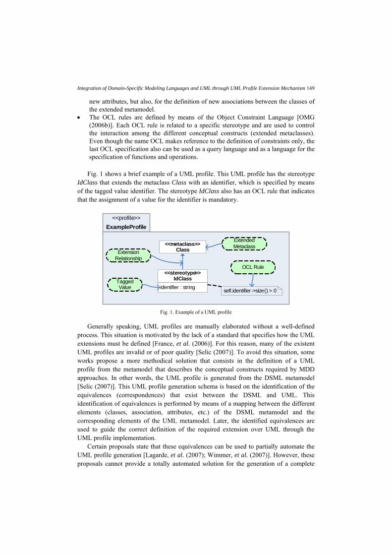
Fig. 1 shows a brief example of a UML profile. This UML profile has the stereotype
IdClass that extends the metaclass Class with an identifier, which is specified by means of the tagged value identifier. The stereotype IdClass also has an OCL rule that indicates that the assignment of a value for the identifier is mandatory.
<<metaclass>>Class
self.identifier ->size() > 0
ExampleProfile
identifier : string
<<stereotype>>IdClass
<<profile>>
Extended Metaclass
Extension Relationship
OCL Rule
Tagged Value
Fig. 1. Example of a UML profile
Generally speaking, UML profiles are manually elaborated without a well-defined process. This situation is motivated by the lack of a standard that specifies how the UML extensions must be defined [France, et al. (2006)]. For this reason, many of the existent UML profiles are invalid or of poor quality [Selic (2007)]. To avoid this situation, some works propose a more methodical solution that consists in the definition of a UML profile from the metamodel that describes the conceptual constructs required by MDD approaches. In other words, the UML profile is generated from the DSML metamodel [Selic (2007)]. This UML profile generation schema is based on the identification of the equivalences (correspondences) that exist between the DSML and UML. This identification of equivalences is performed by means of a mapping between the different elements (classes, association, attributes, etc.) of the DSML metamodel and the corresponding elements of the UML metamodel. Later, the identified equivalences are used to guide the correct definition of the required extension over UML through the UML profile implementation.
Certain proposals state that these equivalences can be used to partially automate the UML profile generation [Lagarde, et al. (2007); Wimmer, et al. (2007)]. However, these proposals cannot provide a totally automated solution for the generation of a complete

Giovanni Giachetti, Beatriz Marín, and Oscar Pastor 150
UML profile. This occurs because, in real MDD approaches, certain structural differences between the DSML metamodel and the UML metamodel may appear. This prevents the automated identification of all the extensions that must be performed in UML.
The proposal presented in [Giachetti, et al. (2008)] defines a solution to solve these structural differences in order to obtain an adequate input for an automated UML profile generation. In addition, considering that the UML profile is generated from the DSML metamodel, during the generation of the UML profile also can be obtained the information of the equivalences (mapping) between the extended UML metamodel (extended with the generated UML profile) and the DSML metamodel. With this mapping information, UML models that are extended with the generated UML profile can be automatically transformed into the equivalent DSML metamodel, and vice versa. The interchange proposal presented in this article is based on this idea. The UML profile generation process developed to put in practice our interchange proposal is presented in the following section.
3. A UML Profile Generation Process
Our interchange proposal is based on a process that allows the automatic generation of a UML profile. This UML profile generation process is centered on three main elements: 1) the definition of an appropriate input that allows the identification of all required UML extensions that must be defined in the UML profile, 2) the identification of the required UML extensions must be performed in a completely automated way, and 3) the automatic definition of the UML profile according to the required UML extensions identified. These three elements were considered in the definition of the three steps that comprise the proposed UML profile generation process, which is presented in Figure 2. This process uses the DSML metamodel related to a MDD approach to obtain an appropriate input (step 1 of the process) for the automatic UML profile generation (steps 2 and 3 of the process). In the definition of this process, different works have been considered. Some of these works are: definition of UML profiles using DSML metamodels [Fuentes-Fernández and Vallecillo (2004); Lagarde, et al. (2007); Selic (2007); Wimmer, et al. (2007)], correct use of metamodels in software engineering [Henderson-Sellers B. (2007)], UML profile implementations5, interchange between UML profiles and DSMLs [Abouzahra, et al. (2005)], and new UML profile features introduced in UML [OMG (2007a)].
It is important to mention that the proposed UML profile generation process can be only used in those MDD approaches where the required conceptual constructs can be represented starting from existent UML constructs. This constraint comes from the limitation of the extensions that can be performed with a UML profile, which cannot change the reference metamodel (light-weight extensions). The specification of all the UML conceptual constructs is presented in the UML Superstructure [OMG (2007b)].
5 OMG: Catalog of UML Profile Specifications, http://www.omg.org/technology/documents/profile_catalog.htm

Integration of Domain-Specific Modeling Languages and UML through UML Profile Extension Mechanism
151
Automatic UML Profile Generation
STEP 1Integration Metamodel
Definition
Integration Metamodel+
Mapping InformationIntegration Metamodel
+Mapping Information
+Identified Extensions
DSMLMetamodel
STEP 2Metamodels Comparison
STEP 3Integration Metamodel
Transformation
UMLProfile
Fig. 2. Schema of the UML profile generation process
The process presented in Fig. 2 is composed of three steps:
• Step 1: The first step corresponds to the generation of a special metamodel from the DSML metamodel. This special metamodel, which is called the Integration Metamodel, provides an adequate input for the automatic UML profile generation.
• Step 2: In the second step, a comparison between the Integration Metamodel and the UML metamodel is performed. This comparison automatically identifies the required UML extensions.
• Step 3: In the third and last step of the process, the Integration Metamodel generated in Step 1 is transformed into the final UML profile according to the identified UML extensions.
In order to understand how the interchange between UML and DSML models can be
performed through this UML profile generation process, the three steps of this process are detailed below.
3.1. Step 1: Integration Metamodel Definition
The Integration Metamodel is the proposal presented in [Giachetti, et al. (2008)] to improve the automatic generation of a UML profile. This metamodel allows the abstract syntax represented in a DSML metamodel to be automatically integrated into UML. This metamodel is defined from the DSML metamodel, and it represents the same abstract syntax of the original metamodel. The main difference between the Integration Metamodel and the DSML metamodel is its structure since it is defined to obtain a mapping with the UML metamodel, which allows the automatic identification of the required UML extensions.
The Integration Metamodel has the following features:

Giovanni Giachetti, Beatriz Marín, and Oscar Pastor 152
• It is defined according to the EMOF modeling capabilities, which are defined in the
MOF (Meta Object Facility) specification [OMG (2006a)]. • It is mapped to the UML metamodel taking into account: Classes, Attributes,
Associations, Enumerations, Enumeration Literals, and Data Types. • All the classes from the Integration Metamodel are mapped to classes of the UML
metamodel. This assures that the conceptual constructs of the DSML can be represented from the conceptual constructs of UML.
• The mapping information is included inside of the Integration Metamodel definition by using a special stereotype. Thus, all the information needed to generate a UML profile is integrated in a unique XMI file that is defined according to the OMG Standards.
During the Integration Metamodel definition, the original structure of the DSML
metamodel may be redefined. This redefinition is performed without altering the abstract syntax represented in the DSML metamodel. This is illustrated by the DSML metamodel presented in Figure 3.
MultiplicityElementlower : integerupper : unat
DMAssociation
newAttr2 : stringpart1Lower : intpart1Upper : unatpart2Lower : intpart2Upper : unat
[1..1][1..1]
DSML Metamodel UML Metamodel
DMClassnewAttr1 : string
participant2
memberEnd[2..*]
type [0..1]
Association
Property
Type
TypedElement
Classattr1 : integer
participant1
Fig. 3. DSML metamodel example
Figure 3 shows a DSML metamodel that represents a binary association between classes. In this metamodel, the class (metaclass) DMClass represents classes of a model, and the class DMAssociation represents binary associations. The class DMAssociation has two associations that represent the two participant classes, participant1 and participant2. This class also has four attributes to specify the lower and upper bound of each participant (association ends), these are: part1Lower and part1Upper for participant1, and part2Lower and part2Upper for participant2. In the two classes of the DSML metamodel, attributes for the generic representation of properties are defined. These attributes are newAttr1 for the class DMClass and newAttr2 for the class DMAssociation.
As Fig. 3 shows, the DSML metamodel is mapped to the corresponding classes of the UML metamodel in order to define the equivalences (correspondences) that exist

Integration of Domain-Specific Modeling Languages and UML through UML Profile Extension Mechanism
153
between the two metamodels. For instance, the mapping of the example (see Fig. 3) indicates that the DMClass is mapped to the classes Class and Property. The mapping between DMClass and Class is clear because both metaclasses represent classes of a model. The mapping between DMClass and Property is defined because, in UML, the participant classes of an association are represented by object-valued properties, where the types of these properties correspond to the related classes.
However, the DSML metamodel and the defined mapping information are not enough to automatically identify the extensions that are required to generate the corresponding UML profile. An example of this can be observed in the mapping that is defined among the class DMClass and the UML classes Class and Property. With this mapping, it is impossible to know if the attribute newAttr1 (from DMCLass) must be considered to extend the class Property (by means of a tagged valued defined in the generated UML profile). Or by contrast, it is only an attribute related to the syntax of a class and must not be considered to extend the class Property for the correct representation of an association end. In order to obtain an adequate mapping, an Integration Metamodel is defined from the DSML metamodel (see Fig. 4).
The elements of the Integration Metamodel that are mapped to UML elements are considered equivalent elements of the Integration Metamodel because these elements have correspondence (equivalence) in the mapped UML element. For instance in Fig. 4, the class DMAssociation is equivalent to the UML class Association, and the attribute DMAssociationEnd.lower is equivalent to the UML attribute MultiplicityElement.lower.
lower : integerupper : unat
DMAssociationEnd
lower : integerupper : unat
MultiplicityElement
memberEnd[2..*]
type [0..1]
Integration Metamodel UML Metamodel
DMAssociationnewAttr2 : string
memberEnd [2..2]
type [1..1]Association
Property
Type
TypedElement
DMClassnewAttr1 : string
Classattr1 : integer
Fig. 4. Integration Metamodel for the example
In the Integration Metamodel presented in Fig. 4, it can be observed that the conflicts related to the mapping of the class DMClass are solved by the definition of a new class called DMAssociationEnd, which is equivalent to the UML class Property. Thus, with the mapping obtained for the Integration Metamodel, it is clear that the attribute newAttr1 is only involved in the representation of classes and it must not be considered to extend the class Property.
Giovanni Giachetti, Beatriz Marín, and Oscar Pastor 154
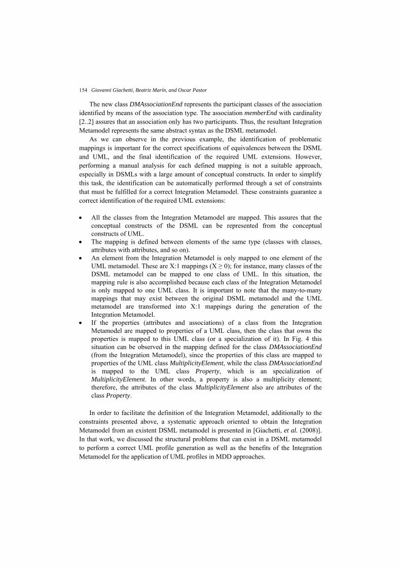
The new class DMAssociationEnd represents the participant classes of the association identified by means of the association type. The association memberEnd with cardinality [2..2] assures that an association only has two participants. Thus, the resultant Integration Metamodel represents the same abstract syntax as the DSML metamodel.
As we can observe in the previous example, the identification of problematic mappings is important for the correct specifications of equivalences between the DSML and UML, and the final identification of the required UML extensions. However, performing a manual analysis for each defined mapping is not a suitable approach, especially in DSMLs with a large amount of conceptual constructs. In order to simplify this task, the identification can be automatically performed through a set of constraints that must be fulfilled for a correct Integration Metamodel. These constraints guarantee a correct identification of the required UML extensions:
• All the classes from the Integration Metamodel are mapped. This assures that the
conceptual constructs of the DSML can be represented from the conceptual constructs of UML.
• The mapping is defined between elements of the same type (classes with classes, attributes with attributes, and so on).
• An element from the Integration Metamodel is only mapped to one element of the UML metamodel. These are X:1 mappings (X ≥ 0); for instance, many classes of the DSML metamodel can be mapped to one class of UML. In this situation, the mapping rule is also accomplished because each class of the Integration Metamodel is only mapped to one UML class. It is important to note that the many-to-many mappings that may exist between the original DSML metamodel and the UML metamodel are transformed into X:1 mappings during the generation of the Integration Metamodel.
• If the properties (attributes and associations) of a class from the Integration Metamodel are mapped to properties of a UML class, then the class that owns the properties is mapped to this UML class (or a specialization of it). In Fig. 4 this situation can be observed in the mapping defined for the class DMAssociationEnd (from the Integration Metamodel), since the properties of this class are mapped to properties of the UML class MultiplicityElement, while the class DMAssociationEnd is mapped to the UML class Property, which is an specialization of MultiplicityElement. In other words, a property is also a multiplicity element; therefore, the attributes of the class MultiplicityElement also are attributes of the class Property.
In order to facilitate the definition of the Integration Metamodel, additionally to the
constraints presented above, a systematic approach oriented to obtain the Integration Metamodel from an existent DSML metamodel is presented in [Giachetti, et al. (2008)]. In that work, we discussed the structural problems that can exist in a DSML metamodel to perform a correct UML profile generation as well as the benefits of the Integration Metamodel for the application of UML profiles in MDD approaches.
Integration of Domain-Specific Modeling Languages and UML through UML Profile Extension Mechanism
155
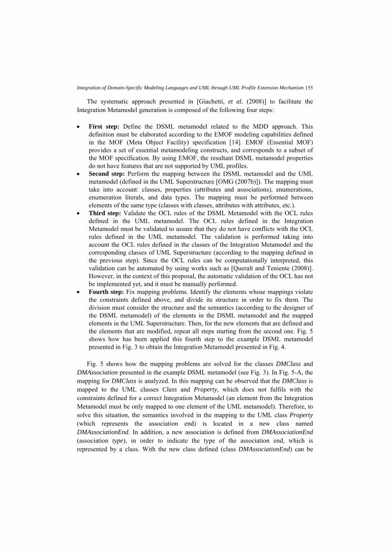
The systematic approach presented in [Giachetti, et al. (2008)] to facilitate the Integration Metamodel generation is composed of the following four steps:
• First step: Define the DSML metamodel related to the MDD approach. This
definition must be elaborated according to the EMOF modeling capabilities defined in the MOF (Meta Object Facility) specification [14]. EMOF (Essential MOF) provides a set of essential metamodeling constructs, and corresponds to a subset of the MOF specification. By using EMOF, the resultant DSML metamodel properties do not have features that are not supported by UML profiles.
• Second step: Perform the mapping between the DSML metamodel and the UML metamodel (defined in the UML Superstructure [OMG (2007b)]). The mapping must take into account: classes, properties (attributes and associations), enumerations, enumeration literals, and data types. The mapping must be performed between elements of the same type (classes with classes, attributes with attributes, etc.).
• Third step: Validate the OCL rules of the DSML Metamodel with the OCL rules defined in the UML metamodel. The OCL rules defined in the Integration Metamodel must be validated to assure that they do not have conflicts with the OCL rules defined in the UML metamodel. The validation is performed taking into account the OCL rules defined in the classes of the Integration Metamodel and the corresponding classes of UML Superstructure (according to the mapping defined in the previous step). Since the OCL rules can be computationally interpreted, this validation can be automated by using works such as [Queralt and Teniente (2008)]. However, in the context of this proposal, the automatic validation of the OCL has not be implemented yet, and it must be manually performed.
• Fourth step: Fix mapping problems. Identify the elements whose mappings violate the constraints defined above, and divide its structure in order to fix them. The division must consider the structure and the semantics (according to the designer of the DSML metamodel) of the elements in the DSML metamodel and the mapped elements in the UML Superstructure. Then, for the new elements that are defined and the elements that are modified, repeat all steps starting from the second one. Fig. 5 shows how has been applied this fourth step to the example DSML metamodel presented in Fig. 3 to obtain the Integration Metamodel presented in Fig. 4.
Fig. 5 shows how the mapping problems are solved for the classes DMClass and
DMAssociation presented in the example DSML metamodel (see Fig. 3). In Fig. 5-A, the mapping for DMClass is analyzed. In this mapping can be observed that the DMClass is mapped to the UML classes Class and Property, which does not fulfils with the constraints defined for a correct Integration Metamodel (an element from the Integration Metamodel must be only mapped to one element of the UML metamodel). Therefore, to solve this situation, the semantics involved in the mapping to the UML class Property (which represents the association end) is located in a new class named DMAssociationEnd. In addition, a new association is defined from DMAssociationEnd (association type), in order to indicate the type of the association end, which is represented by a class. With the new class defined (class DMAssociationEnd) can be

Giovanni Giachetti, Beatriz Marín, and Oscar Pastor 156
observed that the resultant mapping fulfils with the constraints defined for the correct definition of an Integration Metamodel.
Fig. 5-B shows a situation similar to the presented before for the class DMClass. In this figure can be observed that the properties of the class DMAssociation are mapped to properties of the UML class MultiplicityElement, but the class DMAssociation is not mapped to the class MultiplicityElement or to a specialization of this class. This mapping violates the last of the constraints defined for the correct definition of an Integration Metamodel: If the properties (attributes and associations) of a class from the Integration Metamodel are mapped to properties of a UML class, then the class that owns the properties is mapped to this UML class (or a specialization of it). To fix this mapping problem, a new class (DMAssociationEnd) is defined to represent the semantics involved in the mapping from DMAssociation to MultiplicityElement, which corresponds to the cardinality of the association ends. In addition, to keep the relation between an association (class DMAssociation) and the corresponding association ends, the relation memberEnd is defined. The new mapping obtained in Fig. 5-B, also fulfils with the constraints related to the correct definition of an Integration Metamodel.
Fourth Step: Fix mapping problemsA
DSML Metamodel UML Metamodel
DMClassnewAttr1 : string
Property
Classattr1 : integer
DSML Metamodel UML MetamodelDMClass
newAttr1 : string
Property
Classattr1 : integer
DMAssociationEndtype[1..1]
MultiplicityElementlower : integerupper : unat
DMAssociation
newAttr2 : stringpart1Lower : intpart1Upper : unatpart2Lower : intpart2Upper : unat
DSML Metamodel UML MetamodelAssociation
MultiplicityElementlower : integerupper : unat
DMAssociation
newAttr2 : string
DSML Metamodel UML Metamodel
Association
DMAssociationEnd
lower : integerupper : unat
[2..2] memberEnd
CDMAssociation
newAttr2 : string
DSML Metamodel
DMAssociationEnd
lower : integerupper : unat
[2..2] memberEnd
DMClassnewAttr1 : string
DMAssociationEnd
type[1..1]
DMAssociationnewAttr2 : string
DSML Metamodel
DMAssociationEnd
lower : integerupper : unat
[2..2] memberEnd
DMClassnewAttr1 : string
type[1..1]
B
Fig. 5. Example of the fourth step for the systematic Integration Metamodel definition

Integration of Domain-Specific Modeling Languages and UML through UML Profile Extension Mechanism
157
Fig. 5-C shows that the new metaclasses defined to solve the mapping problems related to the classes DMClass and DMAssociation, are representing the same conceptual construct, the ends of an association. Therefore, the results obtained in Fig. 5-A and Fig. 5-B are combined to obtain an appropriate structure for the Integration Metamodel.
Finally, the second step of the systematic approach presented must be applied over the new class obtained (DMAssociationEnd) as well as the modified classes (DMClass and DMAssciation) in order to obtain the final Integration Metamodel (presented above in Fig. 4).
It is important to remark that the systematic approach presented for the definition of the Integration Metamodel is iterative and finishes when all the mapping problems are solved.
Each time that the application of the fourth step of the systematic approach implies a change in the original DSML metamodel (such as in the example), then a mapping between the modified elements (the resultant Integration Metamodel) and the original elements (the DSML metamodel) is specified. This mapping information is used to validate that the resultant Integration Metamodel represents the same syntax as the original DSML metamodel, but also, for the interchange of UML and DSML models.
The mapping information obtained for the example is presented in Table 1. This Table shows that the first and second instances of the association memberEnd represent the first and second participant classes of an association.
Table 1. Mapping information between the DSML metamodel and the Integration Metamodel.
DSML Metamodel Integration Metamodel DMClass DMClass .newAttr1 .newAttr1 DMAssociation DMAssociation .newAttr2 .newAttr2 .part1Lower .memberEnd(1).lower .part1Upper .memberEnd(1).upper .part2Lower .memberEnd(2).lower .part2Upper .memberEnd(2).upper
The obtained Integration Metamodel is the input required for the automatic UML
profile generation, which corresponds to the second and third steps of the UML profile generation process (see Fig. 2).
3.2. Step 2: Metamodels Comparison
The second step allows the automatic identification of the required UML extensions through a comparison between the Integration Metamodel and the UML metamodel. To perform this comparison, the mapping information defined in the Integration Metamodel is used.
The automatic comparison between the Integration Metamodel and the UML metamodel considers:

Giovanni Giachetti, Beatriz Marín, and Oscar Pastor 158
• The identification of new elements, which are the elements from the Integration Metamodel that are not equivalent (mapped) to UML elements. These elements can be attributes, associations, enumerations, literal values, and data types.
• The identification of differences in type or cardinality of equivalent properties (attributes and associations). For instance, for the identification of type differences in the example Integration Metamodel, the association DMAssociation.memberEnd has the same type as the UML association Association.memberEnd because, according to the defined mapping, the class DMAssociationEnd is equivalent to the UML class Property. In the case of the equivalent association DMAssociationEnd.type that is mapped to the UML association Property.type, there exists a type difference because the class DMClass is not equivalent to the UML class Type. The cardinality differences are identified analyzing the lower and upper bound of the equivalent properties and the referenced UML properties. This is the case of the equivalent properties DMAssociation.memberEnd and DMAssociationEnd.type, which have a difference in the upper bound and lower bound cardinality.
The result of the comparison obtained for the example is presented in Table 2. In this
table, the Difference column shows what the differences are by indicating (when necessary) the values for the Integration Metamodel element (I.M.) and the UML element (UML).
Table 2. Metamodel comparison results
Integration Metamodel Difference DMClass.newAttr1 Different type:
I.M. = string; UML = integer DMAssociation.memberEnd Different upper bound:
I.M. = 2; UML = * DMAssociation.newAttr2 New attribute DMAssociationEnd.type Different lower bound:
I.M. = 1; UML = 0 Different type: I.M. = DMClass; UML = Type
3.3. Step 3: Integration Metamodel Transformation
The transformation of the Integration Metamodel into the corresponding UML profile is driven by a set of 11 transformation rules [Giachetti, et al. (2009)]. The features of these transformation rules that are relevant for the interchange proposal are presented below: • Each class of the Integration Metamodel is represented by a stereotype of the
generated UML profile. • The equivalent elements are represented with the corresponding UML elements,
according to the mapping defined in the Integration Metamodel. If there are differences in equivalent elements according to the results obtained in the metamodel comparison (Step 2 of the UML profile generation process), then these differences

Integration of Domain-Specific Modeling Languages and UML through UML Profile Extension Mechanism
159
are managed with OCL constraints. However, there are equivalent elements whose differences cannot be managed with OCL constraints. In these cases, an element defined in the UML profile replaces the original UML element.
• The new elements identified in the metamodel comparison are directly represented in the UML profile.
To obtain the corresponding UML profile from the example Integration Metamodel
(presented in Fig. 4) and the results obtained in the comparison of this Integration Metamodel and the UML metamodel (presented in Table 2. ), the first five transformation rules of the proposal presented in [Giachetti, et al. (2009)] are applied. These transformation rules are presented below.
Rule 1: One Stereotype for each equivalent class. The stereotype extends the referenced UML class, and its name is equal to the equivalent class name. According to this first rule, three stereotypes must be defined in the UML Profile.
Rule 2: One tagged value for each new property. The tagged value must have the
same type and cardinality as the new property. The name of the tagged value must be the name of the new property. In the case of an association, the tagged value must have the same aggregation kind as the new property.
Rule 3: One OCL constraint if the lower bound of an equivalent property is higher than the lower bound of the referenced UML property:
self.[property]->size() >= [newLowerBound]
Rule 4: One OCL constraint if the upper bound of an equivalent property is lower than the upper bound of the referenced UML property:
self.[property]->size() <= [newUpperBound]
Rule 5: One tagged value that replaces a UML property when one of the following conditions holds: • The type of equivalent property is different than the type of the referenced UML
property, and the new type is not a specialization of the original type or a stereotype that extends the original type.
• The upper bound of the equivalent property is higher than the upper bound of the referenced UML property.
• The lower bound of the equivalent property is lower than the lower bound of the referenced UML property.
The presented transformation rules also generate elements to validate the correct application of the generated UML profile. However, the generation of these validation elements is omitted since is not relevant to understand the interchange proposal presented in this work.
Fig. 6 shows the UML profile obtained from the Integration Metamodel of the example after the application of the 5 transformation rules presented above.

Giovanni Giachetti, Beatriz Marín, and Oscar Pastor 160
UML Profile
<<metaclass>>Class
<<stereotype>>DMClass
<<metaclass>>Association
<<stereotype>>DMAssociation
<<metaclass>>Property
<<stereotype>>DMAssociationEnd
self.memberEnd->size =< 2
newAttr1 : stringnewAttr2 : string
self.type->size >= 2
Fig. 6. Generated UML profile
In Fig. 6 can be observed that after the application of the first transformation rule the classes DMAssociation, DMClass, and DMAssociationEnd are represented by three stereotypes with the same names.
According to the second transformation rule, the new attribute DMAssociation.newAttr2 is represented by means of a tagged value that is defined in the stereotype DMAssociation.
The association DMAssociationEnd.type is equivalent to the UML association Property.type, which inherited from the UML class TypedElement (see Fig. 4). However, this equivalent association presents an upper bound difference that must be managed according to the second transformation rule. Thus, an OCL is defined in the stereotype DMAssociationEnd. A similar situation can be observed in DMAssociation.memberEnd, where the upper bound difference is managed by means of the application of the fourth transformation rule, generating a new OCL rule in the stereotype DMAssociation.
For the attribute DMCLass.newAttr1, the type difference cannot be managed with an OCL constraint. This type difference is considered in the first of three conditions for the application of the transformation rule number 5: the type of equivalent property is different than the type of the referenced UML property, and the new type is not a specialization of the original type or a stereotype that extends the original type. Therefore, according to this transformation rule, the tagged value newAttr1 is defined in the stereotype DMClass to replace the original UML attribute Class.attr1.
An interesting characteristic that can be observed in this transformation example is that each element of the Integration Metamodel can be represented by an element of the UML metamodel or by an element of the UML profile. Therefore, it is possible to transform a UML model that is extended with the generated UML profile into an equivalent model defined according to the Integration Metamodel constructs. However, to achieve this transformation, the equivalences (mapping) between the elements of these two metamodels must be known. This mapping takes special relevance for those structural elements (such as tagged values) that where generated in the transformation process and that are not identified in the original mapping of the Integration Metamodel to the UML metamodel.

Integration of Domain-Specific Modeling Languages and UML through UML Profile Extension Mechanism
161
Therefore, the transformation rules not only generate the UML profile, they also generate the mapping between the Integration Metamodel and the UML metamodel that is extended with the obtained UML profile.
Fig. 7 shows graphically the mapping obtained between the Integration Metamodel and the UML profile generated in the example.
Integration Metamodel UML Metamodel + UML Profile
lower : integerupper : unat
DMAssociationEnd
lower : integerupper : unat
MultiplicityElement
memberEnd[2..*]
type [0..1]
memberEnd [2..2]
type[1..1]
Class
Association
Property
Type
TypedElement
<<stereotype>>DMAssociationEnd
DMClassnewAttr1 : string
<<stereotype>>DMClass
newAttr1 : string
DMAssociationnewAttr2 : string
<<stereotype>>DMAssociationnewAttr2 : string
Fig. 7. Mapping for the generated UML profile
The mapping between the Integration Metamodel and the generated UML profile is generated according to the following guidelines:
• Each class from the Integration Metamodel is mapped to the stereotype generated
from this class (transformation rule number 1). • Each equivalent element of the Integration Metamodel is mapped to the
corresponding UML elements, except for those elements with differences that cannot be represented by means of OCL rules. In that case, the equivalent element is mapped to the element of the UML profile that is defined to replace the original UML element (transformation rule number 5).
• Each new element of the Integration Metamodel is mapped to the corresponding element of the generated UML profile (transformation rule number 2).
It is important to note that the definition of OCL rules (transformation rules 3 and 4) not generates new structural elements that must be considered in the interchange of DSML and UML models. However, is important to know how these rules are generated for the correct representation of the final UML profile and to understand the design decisions involved in the final mapping generated between the Integration Metamodel and the extended UML metamodel.
Next section shows how the mapping information obtained during the UML profile generation process can be used to interchange UML and DSML models.

Giovanni Giachetti, Beatriz Marín, and Oscar Pastor 162
4. The DSML and UML Interchange Proposal
The interchange proposal requires two model transformations (see Fig. 8) that are performed using the mapping information obtained in the UML profile generation process.
DSMLModel
IntermediateModel
UMLModel
DSMLMetamodel
IntegrationMetamodel
UMLMetamodel
InstanceOf InstanceOf InstanceOf
Model-to-Model Transformation Model-to-Model Transformation
DSML Metamodel – I.M.Mapping
DSML – UML MetamodelMapping
DSML Model to UML ModelUML Model to DSML Model
Fig. 8. Interchange Between DSML and UML models
With this proposal, it is possible to generate DSML models from UML models that are extended with the generated UML profile, and vice versa. For instance, to obtain a DSML model from a UML model, the first transformation generates an intermediate model from the UML model. This intermediate model is an instance of the Integration Metamodel. This first transformation requires the mapping between the Integration Metamodel and the generated UML profile. The second transformation generates the final DSML model from the intermediate model obtained in the first transformation. This second transformation requires the mapping between the Integration Metamodel and the DSML metamodel.
Fig. 9 shows an interchange example that is based on the metamodels and mappings obtained for the example presented in the UML profile generation process (see Section 3). This example represents an association many-to-many between the classes Passenger and Flight. The corresponding model for this association is represented for the UML model that is extended with the generated UML profile, the intermediate model, and the DSML model. Fig. 9 also shows how can be performed the transformation from one model to other by means of the correspondences between the elements of each model, which are defined according to the mapping obtained in the UML profile generation. In this figure, the name of the association ends in the UML model has been omitted because it is not relevant for the model interchange.

Integration of Domain-Specific Modeling Languages and UML through UML Profile Extension Mechanism
163
<newAttr1> value1
<newAttr1>value2
<Association> passsenger_flight<<DMAssociation>>
<Property> [0..*]
<<DMAssociationEnd>>
<Property> [0..*]
<<DMAssociationEnd>>
<Class>Passenger
<<DMClass>>
<Class>Flight
<<DMClass>>
<newAttr2> value3
<newAttr1> value1
<newAttr1>value2
<DMAssociation> passsenger_flight
<DMAssociationEnd> [0..*]
<DMAssociationEnd> [0..*]
<DMClass>Passenger
<DMClass>Flight
<newAttr2> value3
<newAttr1> value1
<newAttr1>value2
<DMAssociation> passsenger_flight
<DMClass>Passenger
<DMClass>Flight
<newAttr2> value3<part1Lower> 0<part1Upper> *<part2Lower> 0<part2Upper> *
UML Model
Intermediate Model
DSML Model
Fig. 9. Example models obtained in the interchange proposal
A recommended strategy for the implementation of the required model transformations is the use of model-to-model transformation technologies such as QVT or ATL. Thus, an interesting open-source implementation alternative is the Eclipse ATL project, which performs model transformations by means of a mapping that is defined between Ecore metamodels (EMF Project). In addition, the Eclipse ATL project also provides support to perform transformations over UML models that are defined with the Eclipse UML2 project6.
The proposal of Abouzahra et al. presented in [Abouzahra, et al. (2005)] shows a practical approach based on ATL that can be useful to learn how transform a UML model extended with a UML profile into another target model. To perform this transformation, the manual definition of a mapping between the UML profile and the metamodel related to the target model is required. In our proposal, this mapping corresponds to the mapping between the UML profile and the Integration Metamodel, which is automatically obtained. Thus, the Abouzahra et al. proposal could be an interesting open-source solution to implement the transformations between the UML model and the intermediate model that is presented in the interchange proposal. However, it is still necessary to implement the transformations in order to obtain the DSML model from the intermediate model, and vice versa.
6Eclipse UML2 Project, http://www.eclipse.org/uml2/

Giovanni Giachetti, Beatriz Marín, and Oscar Pastor 164
Nevertheless, it is important to remark that for the implementation of the interchange proposal can be used other transformation alternatives, which are different than model-to-model transformations, for instance, by means of XSLT transformations.
The next section shows how has been applied the interchange proposal in an industrial MDD solution, and presents a brief example of this implementation.
5. Applying the Interchange Proposal
The proposed interchange proposal has been applied to an industrial MDD solution that is called OlivaNova7 (the Programming Machine) [Pastor, et al. (2004)]. Olivanova corresponds to the industrial implementation of the OO-Method approach [Pastor, et al. (2001)]. Olivanova has been selected because it already has a suite of MDD tools that are based on the OO-Method DSML. Thus, by applying our interchange proposal to Olivanova, UML-based tools can be integrated with the existent Olivanova technology.
In the suite of Olivanova tools, there are two tools that are oriented to interchange UML and OO-Method models. These tools are the OO-Method XMI importer, which transforms an UML model into an OO-Method model, and the OO-Method XMI exporter, which transforms an OO-Method model into an UML model. The transformations performed by these tools are implemented through XSLT transformations.
However, the interchange provided by these interchange tools is limited by the UML modeling capabilities because the UML constructs do not provide all the precision required by the OO-Method conceptual model. In order to solve this problem, a UML profile that extends UML with the precision required by OO-Method has been defined using the generation process presented in Section 3. The mapping information obtained during the generation of the UML profile has been used to extend the OO-Method interchange tools in order to improve the interchange between UML and OO-Method models. In order to perform this improvement, the transformations required by the interchange proposal are implemented by means of XSLT transformations. This implementation decision has been taken because the OO-Method interchange tools are originally based on XSLT.
The implementation schema that is used to apply the interchange proposal in the Olivanova technology is presented in Fig. 10. According to this schema, the OO-Method metamodel is used as input for the UML profile generation process.
Fig. 10 shows that the UML profile generation process also generates the mappings required to perform the model transformation involved in the interchange of UML and OO-Method models. It is important to note that the mapping between the Integration Metamodel and the UML metamodel is automatically generated during the automatic UML profile generation process.
In the importation process, the XMI importer tool uses as input the XMI definition of the UML model (extended with the generated UML profile) and generates as output an
7 CARE-Technologies Web site, http://www.care-t.com/

Integration of Domain-Specific Modeling Languages and UML through UML Profile Extension Mechanism
165
equivalent OO-Method model, which is represented in XML format according to a specific DTD. The exportation process performs the opposite transformation, it takes as input the XML representation of an OO-Method model and generates as output an equivalent UML model. Therefore, the XMI definition of the UML model can be used by UML-based tools, and the XML definition of the OO-Method model can be used by the different Olivanova tools and by the Olivanova model compilers.
UML Profile Generation Process
OO-Method Importer/Exporter Tools
OO-Method Model
Transformation
OO-MethodIntermediate
Model
UML Model Transformation
UML Class Model
Automatic UML Profile
Generation
OO-MethodObject Model
UML ToolsI.M. – UML Metamodel
Mapping
OO-Method UML Profile
DSML Metamodel – I.M.Mapping
Integration MetamodelDefinition
OO-MethodMetamodel
Olivanova Tools
Olivanova Model Compilers
Software Products
XML Representation
XMI Representation
Fig. 10. Schema for the implementation of the interchange proposal in OO-Method
The interchange between OO-Method and UML is centered on the OO-Method object model, which is similar to the UML class model. Therefore, the interchange tools are focused on transforming an OO-Method object model into an UML class model, and vice versa. However, the OO-Method object model is only one of the diagrams involved in the

Giovanni Giachetti, Beatriz Marín, and Oscar Pastor 166
definition of the OO-Method conceptual model, which is used by the Olivanova technology to automatically generate software applications throw a MDD process. There are other diagrams involved in the definition of the OO-Method conceptual model, for instance, the Presentation Model, which allows the user interface of the generated applications to be defined.
The object model has been selected for the interchange between OO-Method and UML because it is the core diagram for the definition of the OO-Method conceptual model. In addition, due to its proximity with the UML class model, it could be more intuitive for defining the OO-Method object model using UML tools for those customers that already have experience in UML.
Fig. 11 shows a UML model that has been defined using the UML profile generated to represent the concepts of the OO-Method association. This UML model describes the same example presented in Fig. 9 (an association between the classes Passenger and Flight). Fig. 11 also shows the description of the UML model in a tree view, where the application of the different stereotypes can be observed.
Fig. 11. UML model extended with the OO-Method UML profile

Integration of Domain-Specific Modeling Languages and UML through UML Profile Extension Mechanism
167
It is important to note that even though the OO-Method association is a binary association as the example presented in the UML profile generation process, the OO-Method association requires additional properties that are not defined in that simplified example.
The UML model presented in Fig. 11 has been specified using the Eclipse UML2 tool. This figure shows some of the OO-Method concepts that do not exist in UML, for instance, the concept of shared event that is represented by the stereotype sharedEvent. The shared events are services that are defined to manage the creation or destruction of links between instances of associated classes. Fig. 11 also shows that the representation of the OO-Method class is performed by the stereotype oOmClass.
Later, this UML model is transformed into an equivalent OO-Method object model by means of the XMI importer tool (see Fig. 12).
…….
Fig. 12. XMI importer application example
The XMI importer tool uses the mapping information obtained in the generation of the OO-Method profile (see Fig. 10) to perform the transformations presented in the interchange proposal (see Fig. 8).
The presentation model can be defined from the obtained OO-Method object model using the OO-Method presentation model editor, which is based on the OO-Method DSML. Fig. 13 shows a screenshot of this tool, which presents a partial view of the presentation model related to the imported UML model. This figure shows that the executable application will have two Population Interaction Units (PIU) to represent the

Giovanni Giachetti, Beatriz Marín, and Oscar Pastor 168
instances related to each class of the model. A PIU represents an entry-point for the application, through the presentation of a set of instances of a class. An instance can be selected, and the corresponding set of actions and/or navigations specified in the presentation model are offered to the user. More details can be found in [Pastor and Molina (2007)].
Fig. 13. OO-Method presentation model
Fig. 14 shows a screenshot of the application that is generated from the imported UML class model and the defined OO-Method presentation model. This figure also shows that the association between the classes (defined in the UML model) is used to implement the navigation between related instances.
Passengers related to the flight 1
Fig. 14. Generated application
Finally, the imported UML model can also be used to obtain other software products; for instance, to obtain the functional size of the modeled application with the OO-Method

Integration of Domain-Specific Modeling Languages and UML through UML Profile Extension Mechanism
169
function points tools [Giachetti, et al. (2007); Marín, et al. (2008)] in order to estimate the cost of the generated application. Fig. 15 shows a general view of the report of function points that has been automatically generated from the example UML model. This report presents the functional size obtained by a measurement procedure defined according to the IFPUG FPA standard [ISO/IEC 20926 (2003)].
Fig. 15. Functional size report generated for the application generated from the example UML model
6. Related Work
Nowadays, the use of model transformations directed by metamodels mappings seems to be the most appropriate way for the interchange of models that are related to model-based technologies. In this context, certain works have proposed alternatives to facilitate the definition of the required mappings and transformations, such as [Falleri, et al. (2009)]. This work presents a proposal to perform an automatic metamodel matching. The metamodel matching is obtained by means of the transformation of the participant metamodels into directed labeled graphs. The generated labeled graphs are compared by using a similarity algorithm to identify the equivalencies between the different meta-

Giovanni Giachetti, Beatriz Marín, and Oscar Pastor 170
elements, which correspond to the resultant metamodels matching. The obtained matching is used to transform models based on the source metamodel into equivalent models based on the target metamodel. This transformation can be performed by means of model transformation languages such as QVT. However, these kinds of approaches based on the direct transformation of source models into target models do not consider those elements of the source metamodel that have no representation in the target metamodel. Therefore, there is a high probability of lost modeling information in the transformation process. In addition, the precision of the proposed similarity identification algorithm is negatively affected by larger size metamodels, such as the UML metamodel that is considered in our proposal.
If we observe DSMLs and UML, it is very common to find modeling elements in the DSMLs that are not present in UML, this is produced by the nature of UML and DSMLs. UML is a general purpose modeling language, which is defined for its application into different domains. By contrast, a DSML is oriented to a specific domain, and hence, it introduces particular modeling elements for a precise representation of the required software products in the domain context. With the proposal presented in this article, we provide a solution to face the lost of modeling information during the transformation of DSML models into UML models. Thus, it is possible to obtain a complete integration of DSMLs and UML through the bidirectional interchange of DSML and UML models. This solution is centered into the automatic generation of a UML profile that introduces into UML those specific elements of the DSML that are lost in a direct model transformation process. Thus, to continue with the reviewing of the related works, we need to focus on those proposals oriented to the definition of UML profiles, taking special attention in those aspects that can help to the integration of DSMLs and UML.
In the literature, two main working schemas for the definition of UML profiles can be observed: 1) the definition of the UML profile from scratch; and 2) the definition of the UML profile starting from the DSML Metamodel [Selic (2007)], which is the metamodel that describes the conceptual constructs required by a MDD approach. For the interchange proposal presented in this article, the second working schema has been selected since it provides a methodological solution that has more automation possibilities. Thus, the information that is required to perform the interchange of models is automatically obtained through the automation of the UML profile generation.
One of the first proposals related to the generation of a UML profile form a DSML metamodel is the work presented in [Fuentes-Fernández, and Vallecillo (2004)], that proposes some basic guidelines for the UML profile definition. In [Selic (2007)], Selic proposes a systematic approach that takes into account the new UML profile extension features. In addition, this systematic approach establishes some guidelines to ensure a correct DSML metamodel specification. It also defines some criteria to obtain a UML profile by means of a mapping that identifies the equivalences between the DSML metamodel and the UML metamodel. The definition of the mapping between the involve metamodels provides an initial idea about how the UML profile generation can be automated by means of models transformations that are guided by the participant metamodels.

Integration of Domain-Specific Modeling Languages and UML through UML Profile Extension Mechanism
171
In this context, we can found the Lagarde et al. approach [Lagarde, et al. (2007)], which performs a partial automation through the identification of a set of specific design patterns. This approach requires a manual definition of an initial UML profile skeleton, which provides the information of the equivalencies between the DSML metamodel and the UML metamodel. This UML profile skeleton is used instead of the mapping between the involved metamodels. However, to generate the UML profile skeleton, it is necessary to know how the UML profiles are defined, which is opposite to the idea of the automatic UML profile generation that is oriented to encapsulate the complexity of the UML profile definition. In addition, since the patterns provided are only focused on a subset of the DSML metamodel constructs, the generation of the UML profile is not complete.
Another interesting work is presented in [Wimmer, et al. (2007)]. This work proposes a semi-automatic approach that introduces a specific language to define the mapping between the DSML metamodel and the UML metamodel. This mapping allows an automated UML profile generation. However, this approach does not support all the possible mapping alternatives, for instance, the mapping M:M (many elements of the DSML metamodel mapped to many elements of the UML metamodel). As a consequence, the effective application in real MDD approaches is not possible.
In general, none of the works mentioned above provide a sound transformation process to automatically generate a complete UML profile solution. The main limitation of these approaches comes from the structural differences between the DSML metamodel and the UML metamodel such as the example presented in Fig. 3. For this reason, we consider the generation of an Integration Metamodel [Giachetti, et al. (2008)] from the DSML metamodel in order to obtain an appropriate input for the automatic UML profile generation, which integrates the abstract syntax that is represented in a DSML metamodel into the UML metamodel. The transformation rules to perform this automatic generation are presented in [Giachetti, et al. (2009)].
Nevertheless, as this article shows, the automatic UML profile generation can provide another interesting result, which is the mapping information that allows the interchange between the DSML and UML based models to be performed. In this context, proposals such as [Abouzahra, et al. (2005)] state that it is possible to automate the interchange of UML models extended with a UML profile and DSML models by means of model transformations. However, this proposal requires the manual definition of a mapping between the DSML metamodel and the UML metamodel extended with the UML profile. Since this mapping is defined independently of the definition of the UML profile, there exists the risk that the obtained mapping does not reflect the equivalencies between the participant metamodels in a correct way. In our proposal this risk is avoided because the mapping is obtained during the UML profile generation. In addition, the complexity related to the correct design of a UML profile is encapsulated in the transformation of the Integration Metamodel [Giachetti, et al. (2009)]. Therefore, the mapping obtained from this transformation provides a correct identification of the equivalencies between the generated UML profile and the DSML metamodel (using the Integration Metamodel as intermediate model).

Giovanni Giachetti, Beatriz Marín, and Oscar Pastor 172
7. Conclusions
In this article, an interchange proposal to obtain a hybrid modeling schema that integrates UML and DSMLs is presented. Thus, the existent UML-based tools can be reused in the application of specific MDD solutions, thereby reducing the effort of implementing specific MDD tools.
The proposed interchange proposal can be obtained by means of the application of a well defined process for the generation of a UML profile, which integrates into UML all the modeling aspects required by a MDD approach. This UML profile generation process is explained by indicating how the automatic definition of the final UML profile can be automatically performed through a set of transformation rules, and the automatic identification of the required UML extensions. To perform this automatic UML profile generation, an Integration Metamodel that is defined from the metamodel of the DSML required by the involved MDD approach must be used as input. This article also shows the main elements of the systematic approach defined in [Giachetti, et al. (2008)] to facilitate the definition of the required Integration Metamodel.
The different steps of UML profile generation process are presented considering the elements that are involved in the interchange of DSML models and UML models extended with the generated UML profile. Thus, the different interchange elements considered are: • How to obtain the mappings of the equivalences that exist between the DSML
metamodel and the Integration Metamodel. • The automatic generation of the UML profiles elements that participate in the
interchange of models. • The automatic generation of the mapping between the Integration Metamodel and the
UML metamodel. • The transformations involved in the interchange of models and the technologies that
can be used to their implementation. In addition, this article also shows how the proposed UML profile generation process and the Interchange proposal are applied to a MDD approach, using the implementation schema performed for an industrial MDD approach as reference. This implementation schema shows that it is possible to combine the use of UML and DSML tools for modeling the conceptual models that are required by MDD approaches, but also the integration with specific MDD tools based on the DSML metamodel to automatically obtain different software products from the extended UML model. Some of the benefits that can be achieved with the implementation schema proposed are: (1) The MDD proposals that already have a commercial structure defined for a
development process based on a specific DSML can use this same structure, without changes, for UML users.
(2) The different MDD tools based on a specific DSML Metamodel can be used in transparent way over extended UML models. This can be observed in the OO-Method model compiler [Pastor, et al. (2004)], and functional size measurement

Integration of Domain-Specific Modeling Languages and UML through UML Profile Extension Mechanism
173
tools [Giachetti, et al. (2007); Marin, et al. (2008))] presented in the Section 5 of this article.
(3) The users of UML technologies that are using the UML profile generated according to the proposed process for the definition of their conceptual models can easily migrate from UML tools to OO-Method tools. In this way, UML users that have already adopted a specific MDD approach can take advantage of the improved functionalities that the specific MDD modeling tools provide for the management of the involved conceptual models.
Since the OO-Method implementation of this interchange proposal cannot be freely
distributed, as further work we plan to finish the development of an open-source tool that implements this solution. This open-source tool is based on the Eclipse platform and uses the UML2, EMF, and ATL technologies for its implementation.
In addition, we are applying the technologies and ideas presented in this interchange proposal to interchange modeling approaches different than UML and OO-Method. Thus, we propose the integration of modeling approaches related Goal-Oriented Requirements Engineering (GORE) solutions, such as i*, with MDD proposals. This integration is oriented to provide a complete development process that goes from the requirement specification to the automatic generation of the final software product.
Acknowledgments
This work has been developed with the support of MEC under the project SESAMO TIN2007-62894.
References
Abouzahra A., Bézivin J., Fabro M.D.D., Jouault F. (2005). A Practical Approach to Bridging Domain Specific Languages with UML profiles. Best Practices for Model Driven Software Development, OOPSLA’05
Bruck J., Hussey K. (2007). Customizing UML: Which Technique is Right for You?. IBM. Falleri J.-R., Huchard M., Mathieu L., Nebut C. (2008). Metamodel Matching for Automatic Model
Transformation Generation, 11th International Conference on Model Driven Engineering Languages and Systems (MoDELS 2008), LNCS, Springer, pp. 326–340.
France R.B., Ghosh S., Dinh-Trong T., Solberg A. (2006). Model-driven development using uml 2.0: Promises and pitfalls. IEEE Computer, vol. 39 nº 2, pp. 59–66.
Fuentes-Fernández L., Vallecillo A. (2004). An Introduction to UML Profiles. The European Journal for the Informatics Professional (UPGRADE), vol. 5 nº 2, 2004, pp. 5–13.
Giachetti G., Marín B., Condori-Fernández N., Molina J.C. (2007). Updating OO-Method Function Points. 6th IEEE International Conference on the Quality of Information and Communications Technology (QUATIC 2007), pp. 55–64.
Giachetti G., Valverde F., Pastor O. (2008). Improving Automatic UML2 Profile Generation for MDA Industrial Development. 4th International Workshop on Foundations and Practices of UML (FP-UML) – ER Workshop. LNCS. Springer, pp. 113–122.
Giachetti G., Marín B., Pastor O. (2009). Using UML as a Domain-Specific Modeling Language: A Proposal for Automatic Generation of UML Profiles. 21st Conference on Advanced Information Systems Engineering (CAiSE'09). LNCS. Springer, pp. 110–124.

Giovanni Giachetti, Beatriz Marín, and Oscar Pastor 174
Harel D., Rumpe B. (2004). Meaningful Modeling: What's the Semantics of "Semantics"? In: IEEE Computer, vol. 37 nº 10, 2004, pp. 64–72.
Henderson-Sellers B. (2007). On the Challenges of Correctly Using Metamodels in Software Engineering. 6th Conference on Software Methodologies, Tools, and Techniques (SoMeT), pp. 3–35.
ISO/IEC 20926 (2003). Software Engineering – IFPUG 4.1 Unadjusted Functional Size Measurement Method – Counting Practices Manual.
Lagarde F., Espinoza H., Terrier F., Gérard S. (2007). Improving UML Profile Design Practices by Leveraging Conceptual Domain Models. 22th IEEE/ACM International Conference on Automated Software Engineering (ASE 2007), pp. 445–448.
Marín B., Giachetti G., Pastor O. (2007). Intercambio de Modelos UML y OO-Method. X Workshop Iberoamericano de Ingeniería de Requisitos y Ambientes de Software (IDEAS’07), pp. 283–296.
Marín B., Giachetti G., Pastor O. (2008). Automating the Measurement of Functional Size of Conceptual Models in an MDA Environment. Product-Focused Software Process Improvement (PROFES 2008). LNCS. Springer, pp. 215–229.
OMG (2006a). MOF 2.0 Core Specification. OMG (2006b). OCL 2.0 Specification. OMG (2007a). UML 2.1.2 Infrastructure Specification. OMG (2007b) UML 2.1.2 Superstructure Specification. Pastor O., Gómez J., Insfrán E., Pelechano V. (2001). The OO-Method Approach for Information
Systems Modelling: From Object-Oriented Conceptual Modeling to Automated Programming. Information Systems, Elsevier Science, vol. 26 nº 7, pp. 507–534.
Pastor O., Molina J.C., Iborra E. (2004). Automated production of fully functional applications with OlivaNova Model Execution. ERCIM News nº 57.
Pastor O., Molina J.C. (2007). Model-Driven Architecture in Practice: A Software Production Environment Based on Conceptual Modeling. 1st edition, isbn: 978-3-540-71867-3. Springer, New York.
Pohjonen R., Kelly S. (2002). Domain-Specific Modeling. Dr. Dobb’s Journal, 2002 Queralt A., Teniente E. (2008). Decidable Reasoning in UML Schemas with Constraints. 20th
Conference on Advanced Information Systems Engineering (CAiSE'08). LNCS. Springer, pp 281–295.
Selic B. (2003). The Pragmatics of Model-Driven Development. In: IEEE Software, vol. 20 nº 5, pp. 19–25.
Selic B. (2007). A Systematic Approach to Domain-Specific Language Design Using UML. 10th IEEE International Symposium on Object and Component-Oriented Real-Time Distributed Computing (ISORC), 2007, pp. 2–9.
Wimmer M., et al. (2007). A Semi-automatic Approach for Bridging DSLs with UML. 7th OOPSLA Workshop on Domain-Specific Modeling (DSM’07), pp. 97–104.