integrating rules and automated planning in business...
TRANSCRIPT

Department of Mathematics and Computer Science
Department of Industrial Engineering & Innovation Sciences
Integrating rules and automated
planning in business processes
by
Juby Joseph Ninan
In partial fulfilment of the requirements for the degree of
Master of Science in Business Information Systems
Supervisors:
Dr. P.M.E. Van Gorp (TU/e)
Dr. H.A. Reijers (TU/e)
Dr. R. Vdovjak (Philips Research)
Eindhoven, August 2014

I
Acknowledgements
First of all, I would like to thank my principle supervisor, Pieter Van Gorp for
introducing me to this interesting research project and providing me continuous support.
During our frequent meetings, he always gave me advice and offered me solutions
whenever I encountered problems in my project. His helpful guidance and encouragement
throughout the entire course of this project is very much appreciated. I would like to thank
Richard Vdovjak, my supervisor from Philips Research who offered me this intern position.
He had sat with me for many long hours and discussed various aspects of this project in
depth, which was of great value to my work. He has inspired and motivated me throughout
the entire process.
I would like to thank Hui Yan, Shan Nan and Goppy Gustaman who was always there to
help me whenever I had questions or doubts in my research. The brainstorming sessions
with them were not only insightful, but also enjoyable. I would also like to thank Hajo
Reijers who patiently listened to my problems and gave me advice.
Many thanks to the developers from the JBoss Community; specifically Mauricio Salatino
and Geoffrey De Smet for helping me understand certain concepts and guiding me through
technical difficulties.
A special thanks goes out to my friends and fellow graduates who have been there to
support and assist me in the past six months, especially Konstantinos Traganos, Igor
Stojanov, Ekaterina Sabelnikova and Kritika Maurya.
Most importantly I would like to thank my parents and my sister for their unconditional
love and support. They always believed in me and encouraged me to do my best.
Juby Joseph Ninan
Eindhoven, August 2014
II
Abstract
Healthcare organizations are investigating the use of workflow management systems
to support care processes. However the typical workflow management support systems fall
short with regard to providing flexibility and they typically do not deal with the planning
and scheduling of healthcare resources. Due to the complex and dynamic nature of
healthcare processes, flexibility is an important issue to be considered when using systems
that automate the flow of activities in the healthcare environment. Additionally, since the
performance of processes in terms of cost and time depends largely on the availability and
capacity of resources, resource planning is an important issue to be considered when
executing processes. This thesis will demonstrate how flexibility by design and flexibility by
under-specification can be achieved by combining processes with rules. Furthermore, we
will show how resources can be allocated to healthcare processes by integrating them with
an automated planning system. To do this, the KIE group of open-source java projects
developed by the Red Hat JBoss Community will be used, specifically the jBPM project for
business process management, the Drools project for business rule management and
OptaPlanner, a framework to solve planning problems. In order to use these projects,
various technical issues had to be overcome, mostly regarding jBPM. Many problems were
identified and documented during modeling, execution and simulations of processes. Some
of these problems were also reported to the developers of the JBoss community and fixes in
later versions were also tested.
III
Contents
Acknowledgements ........................................................................................................................ I
Abstract ........................................................................................................................................... II
Contents ......................................................................................................................................... III
List of figures ................................................................................................................................ VI
List of tables ................................................................................................................................ VIII
1 Introduction ................................................................................................................................. 1
1.1 Background ......................................................................................................................... 1
1.2 Problem Context ................................................................................................................. 3
1.2.1 Issue of flexibility in WfMS ......................................................................................... 3
1.2.2 Issue of Resource Planning in WfMS .......................................................................... 4
1.3 Purpose of study ................................................................................................................. 5
1.4 Research questions .............................................................................................................. 5
1.5 Research methodology ....................................................................................................... 6
1.6 Research scope .................................................................................................................... 7
1.7 Thesis structure ................................................................................................................... 8
2 Research Preliminaries ........................................................................................................... 10
2.1 Business Rule Management System ................................................................................ 10
2.1.1 Drools rule engine ...................................................................................................... 11
2.1.2 Working execution of Drools rule engine................................................................. 12
2.2 Business Process Management System ........................................................................... 14
2.2.1 Components in jBPM ................................................................................................. 14
2.2.2 Features supported by jBPM ..................................................................................... 17
2.3 Automated Planning and Scheduling ............................................................................. 18
2.3.1 OptaPlanner ................................................................................................................ 19
2.3.2 Solving a planning problem using the OptaPlanner framework ........................... 20
3 Interplay between jBPM, Drools and OptaPlanner ........................................................... 23
3.1 Integrating Drools Rules in jBPM processes ................................................................... 23
IV
3.1.1 Stateless Interaction with the Drools rule engine .................................................... 24
3.1.2 Stateful interaction with the Drools rule engine ...................................................... 25
3.2 Integrating OptaPlanner in jBPM .................................................................................... 26
3.2.1 Creating a work item definition ................................................................................ 27
3.2.2 Creating a work item handler ................................................................................... 27
3.2.3 OptaPlanner work item ............................................................................................. 28
4 Case Description ..................................................................................................................... 29
5 Applying the integration of KIE projects on the case ........................................................ 32
5.1 Part 1 of case ...................................................................................................................... 32
5.1.1 Overview of the planning problem ........................................................................... 32
5.1.2 Applying the OptaPlanner Framework .................................................................... 33
5.1.3 Integrating OptaPlanner with jBPM ......................................................................... 37
5.2 Part 2 of case ...................................................................................................................... 40
5.2.1 Integrating Drools rules in jBPM.............................................................................. 40
5.2.2 Designing flexible processes using rules ................................................................. 42
6 Conclusions ............................................................................................................................. 44
6.1 Related Work ..................................................................................................................... 44
6.1.1 Integrating rules with processes ............................................................................... 44
6.1.2 Integrating automated planning and scheduling in processes ............................... 46
6.2 Research Questions ........................................................................................................... 47
6.3 Limitations ......................................................................................................................... 49
6.4 Future Research ................................................................................................................. 50
6.5 Related Commercial Software .......................................................................................... 50
References .................................................................................................................................... 53
Appendix A. History of Drools, jBPM, OptaPlanner ............................................................ 58
Appendix B. BPMN 2.0 Notations ........................................................................................... 60
B.1. BPMN 2.0 notations supported in jBPM 6 ..................................................................... 60
B.2. Workflow patterns in jBPM 6 ......................................................................................... 65
Appendix C. Business Process Simulation ............................................................................. 67
C.1. Business Process Simulation in jBPM 6 ......................................................................... 67

V
C.2. Problems and limitations in jBPM Business Process Simulations ............................... 71
Appendix D. Business Activity Monitoring ........................................................................... 75
Appendix E. Installation and setup of jBPM 6.0.1 ................................................................. 76
E.1. Steps to install jBPM 6.0.1 ............................................................................................... 76
E.2. Steps to create users in jBPM .......................................................................................... 79
E.3. Problems in jBPM ............................................................................................................ 81
Appendix F. Optimization algorithms in OptaPlanner ....................................................... 84
Appendix G. Rules for Pathologist Case Assignment problem ........................................... 85
Appendix H. Creating the OptaPlanner Work Item ............................................................... 89
VI
List of figures
Figure 1: Timeline relating start of thesis research and jBPM versions ...................................... 8
Figure 2: Conceptual diagram of a production rule system (adapted from [16]) .................... 11
Figure 3: Working execution of Drools rule engine (adapted from [15]) ................................. 13
Figure 4: Main components in jBPM (adapted from [15]) ......................................................... 15
Figure 5: Parsing process in jBPM [15] ........................................................................................ 16
Figure 6: Building the solver (adapted from [17]) ...................................................................... 20
Figure 7: Benchmarking in OptaPlanner [17] ............................................................................. 22
Figure 8: Business Rule Task node and its core properties ....................................................... 24
Figure 9: Stateless interaction with the Drools rule engine (adapted from [36]) ..................... 25
Figure 10: Stateful interaction with the Drools rule engine ...................................................... 26
Figure 11: Execution of a work item (adapted from [15]) .......................................................... 28
Figure 12: Flow chart of the skin cancer treatment process ...................................................... 29
Figure 13: Splitting the skin cancer treatment process into two parts ...................................... 31
Figure 14: Identifying the planning entity .................................................................................. 33
Figure 15: Main classes for the problem domain ....................................................................... 34
Figure 16: Implementing hard and soft constraints as rules in the Drools Rule Language .... 35
Figure 17: XML file showing the problem data set for 5 cases and 2 pathologists .................. 35
Figure 18: XML solver configuration .......................................................................................... 36
Figure 19: Assigning case specific details during the consultation and biopsy phase ............ 37
Figure 20: Invoking OptaPlanner as a custom work item ......................................................... 39
Figure 21: Assigning pathologist to perform pathology process .............................................. 39
Figure 22: Rules setting decision variables ................................................................................. 40
Figure 23: Rule at gateway condition .......................................................................................... 41
Figure 24: Dynamic composition of process fragments ............................................................. 42
Figure 25: Timeline showing evolution of Drools, jBPM and OptaPlanner ............................. 59
Figure 26: Sample model .............................................................................................................. 69
Figure 27: Simulation results at the process perspective ........................................................... 69
Figure 28: Simulation results at the process perspective -Timeline feature ............................. 70
Figure 29: Simulation results at the activity perspective ........................................................... 70
Figure 30: Simulation results at the path perspective ................................................................ 70
Figure 31: Simulation engine does not run for the model (1).................................................... 71
Figure 32: Simulation engine does not run for the model (2).................................................... 71
Figure 33: Incorrect behavior for XOR gateway ......................................................................... 72
Figure 34: Sample model 1 for checking resource utilization ................................................... 73
Figure 35: Sample model 2 for checking resource utilization ................................................... 73
Figure 36: Process dashboards ..................................................................................................... 75
Figure 37: Setting system properties (1) ...................................................................................... 76
Figure 38: Setting system properties (2) ...................................................................................... 77
Figure 39: Creating users in jBPM (1).......................................................................................... 79
Figure 40: Creating users in jBPM (2).......................................................................................... 80

VII
Figure 41: Creating users in jBPM (3).......................................................................................... 80
Figure 42: Startup error ................................................................................................................ 81
Figure 43: Project explorer has disappeared in the KIE workbench ......................................... 81
Figure 44: Error in loading the process ...................................................................................... 82
Figure 45: Cannot import BPMN models into the jBPM web based designer ......................... 83
Figure 46: Negative constraints (Hard and Soft score) .............................................................. 85
Figure 47: Scenario where there are 4 cases and 2 pathologists - for Rule 1 ............................ 85
Figure 48: Representing scoring logic for rule 1 ......................................................................... 86
Figure 49: Scenario where there are 4 cases and 2 pathologists – for Rule 2 ........................... 86
Figure 50: Representing scoring logic for rule 2 ......................................................................... 87
Figure 51: Scenario where there are 10 cases and 3 pathologists- for Rule 3 ........................... 88
Figure 52: Standard deviation of complexity of cases assigned to pathologists is zero .......... 88
Figure 53: Creating the WorkItem definition for the OptaPlanner WorkItem ........................ 91
Figure 54: Creating the OptaPlanner WorkItem Handler ......................................................... 92
Figure 55: Mapping OptaPlanner WorkItem Handler to respective WorkItem definition .... 93
Figure 56: Modifying the session template ................................................................................. 93

VIII
List of tables
Table 1: Roles involved in skin cancer treatment process ......................................................... 30
Table 2: Patterns for integrating rules with processes (adapted from [18] [39]) ...................... 45
Table 3: BPMN 2.0 notations supported in jBPM 6 .................................................................... 60
Table 4: Workflow patterns supported in jBPM 6 ...................................................................... 65
Table 5: Simulation properties for the various BPMN 2 constructs supported by jBPM ........ 68
Table 6: Distribution types and their processing time ............................................................... 72
Table 7: Resource utilization at the activity perspective for Sample model 1(in Figure 34) ... 73
Table 8: Resource utilization at the activity perspective for Sample model 2(in Figure 35) ... 74
Table 9: Predefined roles in jBPM 6 [25] ..................................................................................... 79
Table 10: Optimization algorithms supported by OptaPlanner ............................................... 84

1
1 Introduction
This chapter introduces the background and the problem context for this research
in Section 1.1 and Section 1.2 respectively. Then the main purpose of this study is explained
in Section 1.3 and the main research questions are formulated in Section 1.4. The research
approach and scope is discussed in Section 1.5 and Section 1.6 respectively. Finally this
chapter concludes with the outline on how this report is structured in Section 1.7.
1.1 Background
Despite the unprecedented rate of advancements in medical science and technology,
healthcare organizations are constantly facing the challenge of ensuring clinical excellence
and providing quality services to their patients, while reducing operational costs [1]. A
recent study on the global outlook of healthcare identified some major issues that health care
providers will face in 2014. These include a growing aging population and a rising
prevalence of chronic diseases which are expected to drive the demand for healthcare
services. This growing demand is likely to result in a surge in healthcare costs, an uneven
quality of clinical care being delivered and an imbalance in access to care due to workforce
shortages [2].
Due to these increasing healthcare demands, hospitals have to streamline their processes to
deliver high quality clinical care while simultaneously reducing costs. Here workflow
technology can be used to provide support for controlling and monitoring healthcare
processes [3]. Workflow Management Systems (WfMS) can be used to support healthcare
processes by managing the temporal order and correct coordination of various activities in
the process [4]. Studies have shown that implementing clinical care pathways (evidence
based protocols) using WfMS have led to significant improvements in clinical care
performance and reduced costs of care due to shorter length of stay and decrease in the
number of laboratory tests, consultation and imaging procedures [5], [6].
However, attempting to automate the flow of clinical processes can lead to many problems,
because such processes are complex, diverse and require considerable flexibility [7], [3]. A
different number of examinations and treatments may be required even for a group of
patients with the same diagnosis. Additionally, the order in which these examinations and
treatments are carried out may also vary. The care process for a patient needs to be adapted
based on inferences derived from the patient’s medical history, intermediary test results, or
in response to the way the patient reacts to the specific prescriptions or treatments [3]. The
use of workflow technologies in the healthcare domain has often been critiqued due to the
rigidity enforced by first generation WfMS, which restrict hospitals from reacting to process

Chapter 1 Introduction
2
changes and exceptional situations in an agile manner [7]. Since variations in the course of a
disease or treatment process are very common in the clinical environment, there is a need for
designing flexible workflows [4], [7].
Another limitation inherent in existing WfMS is that they do not deal with the planning and
scheduling of resources (resource management/resource allocation) [8]. Even with limited
resources, business processes are expected to be executed within short time periods and at
lower costs. This is especially true for healthcare institutes that are under increasing pressure
to deliver better services to more people using limited financial and human resources [9].
When designing systems to control and monitor processes, it is important to consider how
resources should be allocated based on their periodic availability, fair usage and in a manner
to balance the distribution of their workload [10].
Currently, there are many vendors that provide such Business Process Management Systems
(extensions of WfMS) which are usually expensive commercial products [11]. For instance,
the license cost plus one year maintenance cost for the standard edition for IBM and Oracle’s
Business Process Management (BPM) offering for a small entry level environment is USD
$654,100 and USD $347,700 respectively [12]. The costs (license fee and one year support) for
the advanced editions for the IBM and Oracle’s BPM offering for larger environments is
USD $ 5.3 million and USD $ 1.5 million respectively [12]. On the other hand, open source
BPM software is gaining traction in the market. This is mainly due to possible cost savings,
flexible license agreements and assistance from the open source community to fix bugs and
problems [11].
jBPM, a community project developed by JBoss (a company acquired by Red Hat) is a
pioneering example of an open source BPM suite that is widely used [11], [13], [14]. It has a
light weight, extensible workflow engine at its core that allows for the execution of business
processes using the BPMN 2.0 standard specification [15]. In addition, the Drools Business
Rule Management System (BRMS) and OptaPlanner, an optimization software are amongst
other projects developed by the JBoss Community. The Drools BRMS has a rule engine at its
core and has its own native language (Drools Rule Language) for writing rules [16]; while
OptaPlanner is a local search and optimization tool that can be used to optimize business
resource usage. It is designed to be a light weight, embeddable planning engine which is
used to solve constraint satisfaction problems [17].
The JBoss community follows an agile approach to software development and hence there
are a number of versions of the Drools, jBPM and OptaPlanner projects that are released
every 3-6 months, with performance upgrades, new features, new APIs and fixes for bugs
and errors. The evolution or a brief history of these projects can be seen in Appendix A,
along with a timeline. At the time this research project started, the last official release was
6th version of the Drools, jBPM and OptaPlanner projects. Collectively, these open source
project (Drools 6.0, jBPM 6.0 and OptaPlanner 6.0) have been grouped under an umbrella

Chapter 1 Introduction
3
name called ‘KIE’, an acronym for ‘Knowledge Is Everything‘ [16]. This research investigates
how the projects belonging to the KIE group can be combined to overcome the limitations in
WfMS described earlier, and thereby support processes in the healthcare domain.
This research was carried out in close collaboration with Philips Research, for Philips
Healthcare. They want to introduce a digital platform for their healthcare services. A core
part of this platform includes workflow technologies. However since workflow technologies
are rarely used in healthcare domain, Philips Research cannot evaluate whether current
commercial workflow products can meet all their requirements for healthcare. Hence open-
source projects like those in the KIE group are used because they can be easily extended.
Further Philips also believes that jBPM is a mature product that would fully satisfy their
needs. In this research, the other projects belonging to the KIE group are also explored and
their maturity is evaluated for the purpose of Philips.
1.2 Problem Context
Since deviations from pre-planned processes are quite frequent in hospitals, flexibility is an
important issue to be considered when using a WfMS in the healthcare environment.
Additionally, such systems should also deal with the planning and allocation of healthcare
resources, which are critical for the performance of the processes. In this section, we address
how these two issues can be overcome, by combining projects belonging to the KIE group.
1.2.1 Issue of flexibility in WfMS
WfMS used in the clinical environment should be able to cope with change due to the
complex and dynamic nature of healthcare processes [7]. However adaptation is not one of
the strong suits of the BPM approach. So, in order to accommodate change, new process
models have to be created, new services have to be assembled and existing running process
instances need to be migrated manually [18]. In contrast, the strength of the Business Rule
Management approach lies in its ability to adapt to change. Here desired behavior is
described using rules and these rules can be easily changed since they are formulated in a
declarative manner independent of specific processes, events and other rules [18]. Therefore
it seems favorable to combine business processes with business rules to overcome the
problem of rigidity in business process automation systems.
In clinical procedures, these rules can be used to represent medical knowledge and assist in
decision making when responding to critical events or exceptional situations. They could be
used to evaluate patient’s medical history, signs, lab test results, medications and provide
diagnostic decisions. They could also be used to provide suggestions for treatments, or to
avoid drug prescription errors [4].
The BPM community has recognized the need for flexible workflow systems that are capable
of handling real world exceptions, uncertainty and evolving processes for many years [7]. As

Chapter 1 Introduction
4
a response to these needs, process support paradigms such as adaptive processes and case
handling have been proposed. Adaptive workflow systems (such as ADEPT2) allows for
dynamic changes in the process model of specific running process instances [7]. Workflow
systems that are capable of case handling (such as FLOWer) focuses on the data perspective
rather than the control flow perspective to aid process flexibility [3]. In case handling, the
knowledge worker decides what activities should be performed to achieve a goal for a
specific case based on the information available (rather than a predefined process control
structure) [19].
In this research, we will study how processes designed in jBPM can be combined with rules
written in the Drools Rule Language and executed by the Drools rule engine, to achieve
process flexibility. A taxonomy of flexibility was proposed by [3], where four types of
flexibility (by design, by deviation, by under-specification and by change) for the control
flow perspective was distinguished. However there has been no previously published work,
on how rules can be used to achieve these flexibility types. In this research, the rules used
while designing the processes are also associated to these flexibility types.
1.2.2 Issue of Resource Planning in WfMS
Due to the increasing demand for healthcare services, rising expenditures and workforce
shortages, the planning and scheduling of healthcare resources is vital. These resources,
which include personnel (physicians, nurses, etc.), medical equipment, specialized
laboratories, beds, ambulances, etc., have to be coordinated in such a way so as to offer
successful services on time and within budget for routine and emergency problems [20].
As such, many kinds of planning and scheduling problems can be encountered in the
healthcare domain. Some common problems include the allocation of beds to patients,
allocation of shifts to personnel (nurses, doctors), drug logistics, ambulance scheduling and
operating theatre scheduling [20]. These problems are often NP complete, where it is easy to
verify a solution; however it is difficult to find an optimal solution to the problem in
reasonable time mainly due the large search space of solutions. Moreover these problems
typically have a number of constraints; some of which must not be violated (hard
constraints), while others should not be violated if it can be avoided (soft constraints). The
various complex constraints under which hospital management operates makes the use of
automated planning and scheduling systems essential. As such automated planning and
scheduling is an active area of research within Artificial Intelligence and Operational
Research [20].
Since the performance of processes in terms of cost and time depends largely on the capacity
and availability of resources, it becomes important to develop resource allocation plans.
These resource allocation plans should be considered while processes are being executed,
and then suitable resources can be allocated to process instances at runtime. Planning the
allocation of resources for a large number of process instances also guarantees that the
Chapter 1 Introduction
5
business requirements will be fulfilled [21]. Therefore it seems promising to integrate
automated planning and scheduling systems in a WfMS and similar work can be found in
literature. For instance, the SWIM system by [22] was designed to integrate process
instantiation with task allocation and execution, along with scheduling techniques. The
MILOS system developed by [23] was a process modeling and enactment system which also
provided support for resource allocation and time scheduling of tasks. More recent efforts
included the work of [24], where the authors had presented a generic design and a concrete
implementation approach for a calendar based schedule-aware WfMS.
Although several researchers have investigated how to integrate automated planning and
scheduling systems in a WfMS, there is no previous work found where a planning system
like OptaPlanner is integrated in a process modeled in jBPM. Therefore this research will
demonstrate how OptaPlanner can be used to solve a specific planning problem in the
healthcare domain and how it can be integrated within processes designed in jBPM.
1.3 Purpose of study
The main purpose of this study is to find out how business rules and an automated planning
system can be integrated in a Business Process Management System (BPMS) used in the
healthcare context. To achieve this goal, this research will address how rules (defined in the
Drools Rule Language) can be used to achieve flexibility while designing healthcare
processes in jBPM. It will also address the issue on how to optimally plan the allocation of
healthcare resources using an automated planning system such as OptaPlanner, and how
such a system can be integrated in jBPM. As such this thesis will demonstrate how Drools,
jBPM and OptaPlanner can be made to interact with each other.
1.4 Research questions
Based on the problem context described in Section 1.2, the main research question is
formulated as -
How can the KIE group of open-source projects (namely Drools, jBPM and OptaPlanner)
be used to support processes in healthcare?
In order to answer this question, the following sub research questions have to be answered -
1. How can Drools business rules be used to design flexible processes in jBPM?
2. How can OptaPlanner be used to support the planning of healthcare resources?
3. Can these three projects (Drools, jBPM and OptaPlanner) be combined to offer a
meaningful interaction? If so, how do they interplay and what is the benefit of using
all three at once, as opposed to isolation?
Chapter 1 Introduction
6
Additionally, it is important to note that these questions cannot be simply answered by
looking at the manuals of the projects belonging to the KIE group or their running examples.
1.5 Research methodology
In this section, the approach followed to conduct this research is explained in 5 stages:
Stage 1 – Studying the jBPM Business Process Management Suite
Since there were many versions of jBPM with different documentations and API changes,
the research initially started with a comparison of the features and process modeling
notations supported in jBPM versions 5.4 and 6.0.1 (the last 2 officially released versions).
jBPM 6.0.1 was then chosen for this study, mainly because the entire life cycle of a business
process from authoring through execution to monitoring and management is supported in a
single workbench, which is called the KIE Workbench. Next, the various features supported
in jBPM 6.0.1 were further explored; these included the graphical process modeler (a web
based designer and eclipse based modeler), web based data modeler, web based form
builder, business process simulation capabilities and business activity monitoring.
During process modeling and execution, many problems were identified and documented
with possible workarounds. Some problems which occurred during simulations were
reported to the developers and fixes in versions 6.0.2 and 6.1.0 were also tested. Moreover
the steps to be followed for creating users and assigning them roles and groups were not
correctly specified in the jBPM 6 documentation. A solution for this was found by combining
steps in the documentation of the 5th and 6th versions.
Stage 2- Studying the Drools Business Rule Management System
The second stage of the research involved exploring the Drools Business Rule Management
System. To do this, the working execution of the Drools rule engine had to be studied, along
with learning how to write business rules using the Drools Rule Language (DRL). Only then
could sample projects be tested using the Drools Integrated Development Environment
(IDE) as an Eclipse plug-in.
Stage 3- Studying how to use the OptaPlanner framework
During the third stage of the research, a theoretical understanding on how to use the
OptaPlanner framework to solve a planning problem was necessary. This mainly involved
an understanding of specific annotations used by OptaPlanner when modeling the problem
domain as a set of java classes, configuring the solver to use various optimization algorithms
and defining the fitness function. The fitness function used for calculating the score of a
solution was done by using the Drools Rule Language learnt in the previous stage. Initially
a relatively easy planning problem was tried, with simple constraints. Later this planning
problem was refined and more complex constraints were added. A benchmarking facility

Chapter 1 Introduction
7
provided by OptaPlanner was also tried to compare the performance of various
optimization algorithms w.r.t the specific planning problem.
Stage 4- Integrating Drools rules with business processes in jBPM
The fourth stage of this research involved learning how to use Drools Rules when designing
business processes in jBPM. There were two ways to interact with the Drools Rule Engine
from jBPM – in a stateless or a stateful manner. Interacting with the Drools Rule Engine in a
stateless manner could be done from processes defined from the KIE Workbench. However
the stateful interaction with the rule engine is not completely supported from the KIE
Workbench at the moment. Currently this can be done from an application specific java
project where the jBPM process engine and the Drools Rule engine are embedded.
Stage 5- Integrating a specific OptaPlanner project in jBPM
For the fifth stage of this research, the specific OptaPlanner project created during the third
stage had to be integrated in jBPM. However, after studying the documentation for the
OptaPlanner [17] and jBPM [25] projects provided by the Red Hat JBoss community, soon
led to the realization that there is no out-of-the-box solution for integrating an OptaPlanner
project within jBPM. This was later confirmed by discussing the topic (OptaPlanner–jBPM
integration) with the JBoss community members [26]. In this thesis, the approach developed
to integrate OptaPlanner within jBPM was by using the concept of a domain specific node,
also called a custom work item. To do this, certain parts of the OptaPlanner project had to be
modified so as to work within the jBPM process.
Stage 6- Testing integrations of the Drools, jBPM and OptaPlanner
For the last stage of this research, a simple case describing a healthcare process is introduced
for testing and demonstrating the integration of OptaPlanner and Drools rules in jBPM.
Furthermore, multiple consultation and presentation sessions were held with the
stakeholders within Philips, and the proposed integration designs were presented. This
served as a form of external evaluation for the research conducted.
1.6 Research scope
As a constraint imposed by the collaborating business partner, this thesis only investigates
the Drools, jBPM and OptaPlanner projects belonging to the KIE group. At the time this
thesis research started, the latest official release of jBPM was version 6.0.1. In Figure 1, a
timeline showing when this project started and how it relates in time to the versions of jBPM
can be seen.

Chapter 1 Introduction
8
Figure 1: Timeline relating start of thesis research and jBPM versions
The integration of rules in the design of processes is implemented only from the KIE
Workbench. The other alternative is to use rules in the design of processes through an
application specific java project (where the jBPM workflow engine and the Drools rule
engine is embedded) which is outside the scope of this research. Also when using the
OptaPlanner framework to solve a planning problem, the details on how to configure the
various parameters of the optimization algorithms is not included in the scope of this
research. The values for these parameters will be set based on example OptaPlanner projects
provided by the JBoss community. Further a simple case describing a healthcare process is
used in this thesis to demonstrate the integration of Drools and OptaPlanner in jBPM. The
case is a simplified version of the skin cancer treatment process described in [27]. The case
was also modified to include a planning problem.
1.7 Thesis structure
This section describes the structure of the thesis text.
Chapter 2 introduces the preliminary concepts related to this thesis; this includes the
working execution of the Drools rule engine, the main components and features supported
by jBPM and a description of the OptaPlanner framework.
Chapter 3 describes the interplay between jBPM, Drools and OptaPlanner. In this chapter,
we will describe how Drools rules can be integrated in jBPM processes, and how
Optaplanner can be integrated in jBPM.
Chapter 4 introduces a sample case description of a healthcare process. This process also
comprises of a planning problem.

Chapter 1 Introduction
9
The sample case which was introduced in Chapter 4 is split into two parts in Chapter 5.
The first part which comprise of a planning problem is solved using the OptaPlanner
framework as a standalone project. Then this OptaPlanner project is integrated in a jBPM
process. The second part of the case is used to demonstrate the various ways to integrate
Drools rules in jBPM.
Chapter 6 concludes the thesis with a brief discussion of related work from literature and
then addresses the research questions. The limitations of this research and some directions
for future work are also presented in this chapter. Lastly some commercial software
products similar to the projects belonging to the KIE group are also described.

10
2 Research preliminaries
This chapter introduces preliminary concepts used throughout this master thesis.
The modeling and automation of business behavior can be done using two main
approaches- Business Rule Management or Business Process Management [18]. The
Business Rule Management approach focuses on the use of rules to define business
situations, and tries to describe why something has to happen and uses necessary
technologies to automate decision logic. The second approach focuses on the flow of
activities, and tries to describe what is happening in the business process using visual
constructs or notations, and provides necessary technologies to automate the execution of
business processes [18].
This chapter is structured as follows. Section 2.1 gives a general introduction to Business
Rule Management Systems and then describes the Drools rule engine along with its working
execution. This is followed by a general description of Business Process Management
Systems in Section 2.2, and then an introduction into the jBPM business process
management suite with a brief explanation of the main components it is comprised of, along
with the main features it supports. Section 2.3 gives a general introduction to automated
planning and scheduling and then describes the OptaPlanner framework and explains how
it can be used to solve a planning problem. This chapter concludes with a description on
how to setup the environment to successfully use these projects in Section 2.4.
2.1 Business Rule Management System
" A Business Rule Management System (BRMS) is any software system used to define, deploy,
execute, monitor and maintain artifacts called business rules in operational systems within an
organization " [28].
These business rules are statements that define discrete operational policies and practices to
influence and guide organizational behavior. They are compact statements describing any
facet of a business in an unambiguous language made simple and understandable to all
parties involved. They represent the conditions that determine a business event so that it
occurs in a way acceptable to the business [29].
A BRMS typically allow users to create, update or delete rules through a rule editing facility.
They provide a rule repository where different versions of the business rules can be stored
and managed. They also provide a run time environment for a rule engine to process rules
through a rule execution facility [28].

Chapter 2 Research preliminaries
11
Some of the benefits of using a rule engine in software applications include [29], [28] –
1. Separation of logic and data
The separation of business logic represented as rules from data (or domain objects)
makes the adaptation of logic to policy changes easier to maintain. Since rules are
written in a declarative manner, they are especially useful in situations where the
business logic changes frequently. Then existing rules can be easily modified or new
rules could be easily added.
2. Centralization of knowledge
Since rules are stored and managed from a centralized location, inconsistencies in
business practices can be reduced and duplicate implementation efforts can be
avoided.
3. Understandable rules
Rules can be written in a manner to resemble natural language, thus making them
easy to understand, define and modify by business analysts or domain experts.
One such business rule management system is Red Hat JBoss BRMS, which is based upon
the open-source Drools project, which is a java rule engine. The next section describes the
Drools rule engine and its working execution.
2.1.1 Drools rule engine
The Drools rule engine originated as a Production Rule System (also called Rule Based
System or Production System), which is a type of inference system commonly used to
control reasoning in an expert system and where knowledge is represented as production
rules. A production rule system consists of three main components as shown in Figure 2 –
production memory where production rules reside, working memory where data or facts
reside and an inference engine (or a rule interpreter) [30].
Figure 2: Conceptual diagram of a production rule system (adapted from [16])

Chapter 2 Research preliminaries
12
Production rules are a knowledge representation technique that has a two-part structure,
comprising of a condition and a consequential action [30]. Each production rule in Drools
has the following format:
rule “rule name”
when
// condition that is matched against facts
then
// action that is to be executed
end
In a production system, the rules are stored in the production memory and the facts that are
matched against rules (by the Inference Engine) are asserted into the Working Memory,
where they can be modified or retracted. The inference engine is responsible for matching
facts against production rules, and infers conclusions which result in actions. The process of
matching new or existing facts to the rules is called pattern matching and there are many
algorithms used by inference engines for pattern matching such as Linear Brute Force
Search, Rete, Treat and Leaps. Currently, the sixth version of Drools uses a new lazy
algorithm called PHREAK for pattern matching. The engine can also be configured to use
the ReteOO algorithm, which is an enhanced and optimized implementation of the Rete
algorithm for Object Oriented Systems [16].
Pattern matching can result in conflicting rules, i.e. multiple rules can be concurrently true
for the same asserted fact. The agenda is responsible for managing the execution order of
rules using a conflict resolution strategy. The execution or firing of a rule can change data,
which may result in new facts being inserted in the working memory and in turn be
matched against other rules. This mechanism is referred to as forward chaining and can be
characterized as reactionary or ‘data driven’, as assertion of facts into working memory
results in executions. Although Drools started as a production rule system, the fifth version
of the Drools rule engine introduced backward chaining as well as some functional
programming styles. Hence Drools 5 onwards can be described as a hybrid reasoning
system [16].
The default working execution of the Drools rule engine will be explained in the next
section.
2.1.2 Working execution of Drools rule engine
Information in the object oriented environment is represented as objects. When these objects
are inserted into the working memory of the rule engine, they become facts (according to the
rule engine's terminology) which are evaluated against the defined conditions of the rules.
As a result of the insertion, a wrapper to the object instance (called a FactHandle) is created
and returned to the application. Since the FactHandle is a reference to the fact inserted in
working memory, it is a means to interact with the working memory from the application,

Chapter 2 Research preliminaries
13
so as to modify or remove facts that have been previously inserted. The act of inserting,
modifying or removing facts from working memory is referred to as a Working Memory
Action [16].
During the insertion phase, when there is a fact which matches with the condition of a rule,
the rule and its matched data is put into the Agenda and is referred to as an Activation (or a
Rule Match). The agenda is a table of activations. It is possible that a single Working
Memory Action can result in multiple eligible rules. In such situations, the Agenda controls
the execution order of these matches using a conflict resolution strategy. Drools provides a
number of conflict resolution strategies like salience (rules are given priorities), LIFO (last in
first out), FIFO (first in first out), etc. A single activation is then selected to be fired. Firing
an activation will result in the execution of the consequence/action part of the rule, which
can cause new activations to be created or existing ones to be cancelled. This loop goes on
until the agenda is completely cleared [16]. A conceptual diagram explaining this working
execution can be seen in Figure 3.
Figure 3: Working execution of Drools rule engine (adapted from [15])

Chapter 2 Research preliminaries
14
Thus the engine operates in a cyclic 2 phase mode [31] :
Working Memory Action Phase - In this phase, a working memory action (insert, update, or
retract) takes place from either the main application code or from the execution of the
consequence of a rule.
Agenda Evaluation Phase – In this phase, the engine selects an activation to fire from the
agenda. If there are no activations in the agenda, the engine exits. If there are activations, the
engine will select one and execute it, and then switch back to Working Memory Action
Phase. This process repeats until the agenda is empty.
2.2 Business Process Management System
Although there are many definitions for Business Process Management in literature, we use
one defined by [32] as “Supporting business processes using methods, techniques, and software to
design, enact, control, and analyze operational processes involving humans, organizations,
applications, documents and other sources of information”. It is a discipline that applies
knowledge combined from management science and information technology to operational
business processes [33]. It can be considered as an extension of the traditional Workflow
Management approach that mainly focuses on automating business processes, whereas BPM
has a broader scope and also includes the analysis of processes, management of operations
and the organization of work [32], [33].
As such, a business process management system can be defined as “a generic software system
that is driven by explicit process designs to enact and manage operational business processes” [32].
jBPM, an open-source community project by JBoss initially started as simple workflow
engine used for the enactment of business processes, which has grown significantly in the
last few years, to support the entire business process lifecycle, from process authoring and
analysis, to execution, monitoring and management [15]. In the next section, the main
components involved in the jBPM architecture are explained followed by a description of the
main features supported by jBPM 6.
2.2.1 Components in jBPM
The main components involved in the jBPM architecture are explained in this section. A
conceptual diagram representing the various components and their interactions is shown in
Figure 4.
The core of jBPM consists of a set of components for parsing and executing various kinds of
knowledge assets (processes, rules, etc.) that are stored in a Knowledge Repository. The
Semantic Knowledge Based Module is responsible for defining the language semantics and
how it will be translated to the process engine’s internal structure. It contains several parsers
to handle different types of resource types (BPMN2, DRL, etc.). The jBPM project is built on

Chapter 2 Research preliminaries
15
top of the Drools project; hence the process engine and the rule engine are merged to work
together [15]. The working of the rule engine has been previously explained in Section 2.1.1.
In this section we will focus more on the process engine and the other components.
Figure 4: Main components in jBPM (adapted from [15])
The process engine is responsible for creating new process instances and maintaining their
state. The internal structure representing different activities from the process definition is
defined in the process engine, along with the mechanisms to instantiate the process
definitions and then execute them. The process engine is responsible for creating the process
definition structure and the process instance structure.
The process definition structure is the static representation of the business process. When a
business process is modeled using a graphical process modeler, this graphical representation
is stored as an XML file which is compliant with the BPMN2.0 specifications, which is then
parsed by the BPMN2 parser in the semantic module. The outcome of the parsing process
results in the creation of a structure of objects representing a graph. This structure called the
process definition contains all the activities in the graphical representation [15]. This parsing
process can be seen in Figure 5.

Chapter 2 Research preliminaries
16
Figure 5: Parsing process in jBPM [15]
The process engine then creates an instance of the ‘process instance structure’, for every
process that is to be executed. This structure represents the running process and the
information it should handle. This information is required to keep track of the activities
being created during process execution.
The mechanism to create the process instances depends on the engine implementation. Prior
to the release of the fifth version of jBPM, the process engine used a Token Based Approach
for process executions. In this approach, a token was created for every process instance that
will traverse the process activities and carry the information required for those activities.
The process instance dies when the token reaches the last activity (end node) and the process
is then marked as completed [15].
However, since the release of jBPM 5, the mechanism for process execution was
implemented using the Node Instance Based Approach. In this approach, a new instance
representing the execution status of a particular activity (from the process definition) is
dynamically created. Every time the process execution comes across an activity from the
process definition, its respective node instance is created and placed inside a node instance
collection, which is inside a process instance. When the activity is completed, the node
instance is removed from the collection. Thus this collection or list of node instances
represents the activities that are currently being executed [15].
Processes which take a long period of time to be completed (especially processes involving
human tasks), requires a mechanism to store the state of the running instance, along with the
information it is handling into a file system or a database. The persistence and transaction
component is responsible for defining this mechanism to store the runtime information of
process instances and also decides how and when the process engine transactions have to be
created, committed or roll backed. There is also an Audit/History Logs module which
allows users to query historical data about the processes. This information retrieved is useful
for Business Activity Monitoring and reporting tools [15].
Chapter 2 Research preliminaries
17
During process execution, if there is a user task activity in the process definition, then a
human task is created and the actor responsible for carrying out that task will see a new
activity that needs to be completed in the task list inbox. The Human Task Component is
responsible for managing the life cycle of a human task (created, in progress, suspended,
completed, etc.) through a set of services/APIs that are defined by the Web Services Human
Task (WS-HT) standard specification. It also provides the functionality to design custom
task lists and task forms for the end user. The WS-HT specification is the default
implementation for the human task service provided by jBPM, but it is also possible to
replace it with any custom human task service implementation. The Human Task
Component is made to interact with the process engine, the end user’s interface and an
Identity Component that is capable of interacting with a repository where the user and
group information of the organization is stored. This interaction is required to map the
organizational structure of user and groups to the roles defined in the process [15].
2.2.2 Features supported by jBPM
In this section, some of the features supported by jBPM 6 are described [25]:
1. A web-based designer and an Eclipse based modeler for graphical process modeling
using the BPMN 2.0 standard specification maintained by the Object Management
Group (OMG). A list of BPMN 2.0 notations and workflow patterns supported by
jBPM version 6.0.1 and version 5.4 is mentioned in Appendix B.
2. A data modeler to create data objects along with their attributes (the getters and
setters for each attribute gets automatically defined). The data modeler is used to
create complex data structures like a graph of objects. These data objects can then be
used as process variables within the process definition.
3. A web-based form builder to create process and task forms. These task forms can be
automatically generated from process variables and task variables, and then
customized later using the form editor. These forms are the front end for Human
Tasks within the business process, and are used to display or request data from end
users/ actors.
4. jBPM also supports Business Process Simulation capabilities from the web-based
designer. The simulation is based on Business Process Simulation Interchange
Standard (BPSim) which is a WfMC standard. A detailed explanation of the features
supported by jBPM simulation is explained in Appendix C, along with some
problems encountered during simulations.
5. Tooling for Business Activity Monitoring (BAM) is also supported, which is used for
the creation of dashboards. More details of the BAM feature are explained in
Appendix D.

Chapter 2 Research preliminaries
18
The detailed steps on how to install jBPM 6.0.1 and how to get started with the setup are
explained in Appendix E, along with some problems encountered while designing processes
from the web based designer.
2.3 Automated planning and scheduling
Automated planning and scheduling has been an active area of research within the
Operational Research community and Artificial Intelligence community for a long time [20]
[34]. Here planning is defined as “the process of putting in a sequence or partial order a set of
activities/actions to fulfil temporal and resource constraints required to achieve a certain goal” [20],
whereas scheduling is defined as “the allocation of activities/ actions over time to resources
according to certain performance criteria” [20]. Many researchers consider scheduling as a
special case of planning [20].
Many real world problems can be grouped as planning and scheduling problems, where
resources are to be allocated in a manner so as to optimize performance objectives. One
approach to solve such problems is by using constraint satisfaction techniques, where the
problem is to be modeled as a set of decision variables. Each decision variable will have a set
of possible values and a set of constraints that restrict the allowed combination of values to
variables. Then the task is to find a solution where the values are to be assigned to variables
in a manner so as to satisfy all constraints [35].
Such problems can be solved by using complete search algorithms (Exact algorithms) to
systematically explore the complete solution search space, to find all possible assignments of
values to variables. If a solution to the problem exists, then it is guaranteed that the
algorithm will find the optimal one. If there is no solution to the problem, it can be proved
that the problem is not solvable. However, using such algorithms that perform an
exhaustive search may take a very long time. As an alternative approach, it is possible to use
incomplete search algorithms that do not explore the whole solution search space; but may
still find a reasonable or ‘good-enough’ solution (close to the optimal solution) within a
significantly short period of time. This class of algorithms are called metaheuristics and
include evolutionary algorithms (such as genetic algorithm, evolutionary strategies, etc.) and
local search techniques (such as hill climbing, simulated annealing, tabu search, late
acceptance, etc.) [35].
One software framework used to solve such planning and scheduling problems with
constraint satisfaction techniques is OptaPlanner. It is an open source java project released
under the Apache Software License. In the next sections, we will describe the OptaPlanner
project and the steps to be followed when using it to solve a planning problem.

Chapter 2 Research preliminaries
19
2.3.1 OptaPlanner
“OptaPlanner is a lightweight, embeddable planning engine that optimizes planning problems“ [17].
These planning problems are characterized by the fact that they are NP complete, they have
constraints (usually hard and soft constraints) and they have large search space of solutions
to choose from. This makes it necessary to use automated planning and scheduling systems
to solve such problems. The OptaPlanner project (previously called Drools Planner) is one
such software that can be used to solve constraint satisfaction problems by using a
combination of optimization algorithms (construction heuristics and meta-heuristics) with
efficient score calculations [17].
The logic for calculating the score for every possible solution is defined in the fitness
function. This is an objective way to compare different solutions, and to choose the solution
which has the highest score. The fitness function or the scoring techniques are based on
constraints, which can be a positive constraint (to be maximized), negative constraint (to be
minimized), or a combination of both. The fitness function can be implemented using Java or
the Drools rule engine. Using the Drools rule engine, to calculate the score of a solution
reduces the complexity and effort to write scalable constraints in a declarative manner.
Moreover by using the forward chaining mechanism of the Drools rule engine, allows for
delta based score calculation instead of a full score calculation on each evaluation of a
solution. Then only those constraints that have changes in one or more conditions since the
previous evaluation will be recalculated. This type of score implementation has huge
performance and scalability gains, without the need of writing a complex incremental score
calculation algorithm [17]. In this thesis, the Drools rule engine will be used to perform the
score calculations and every constraint will be represented as rules written in the Drools
Rule Language. This gives the developer the flexibility to easily add new constraints or
modify existing ones [17].
Although the Drools rule engine is efficient at calculating the score of a solution, it is not
suitable for finding new solutions. In order to find new improved solutions, a solver is built
which uses multiple optimization algorithms (construction heuristics, meta-heuristics) in an
ordered sequence. A construction heuristic is first used to get from an empty solution to an
initialized solution. This initialized solution can then be given to the local search algorithm
to find a good solution. At each solution, the local search algorithm (meta-heuristic) will try
all possible moves to change to the next solution. It will then choose the best move with the
highest score as the ‘next step’. The local search algorithm decides which is the ‘next step’
with the help of three configurable components– A MoveSelector which selects/generates all
possible moves of the current solution, an Acceptor which will filter out those moves which
are unacceptable and a Forager which will gather all the accepted moves and choose the best
move which is the next step [17].
Chapter 2 Research preliminaries
20
The next section describes how the OptaPlanner framework can be used to solve a planning
problem.
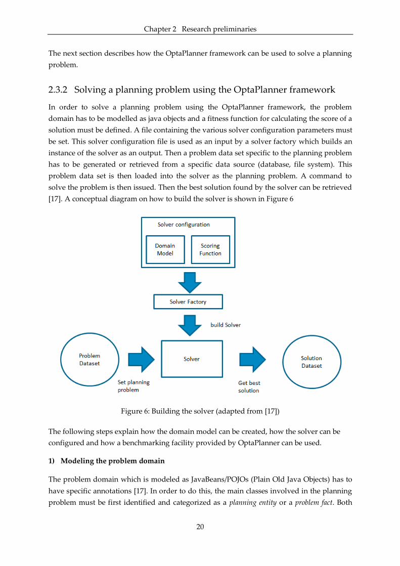
2.3.2 Solving a planning problem using the OptaPlanner framework
In order to solve a planning problem using the OptaPlanner framework, the problem
domain has to be modelled as java objects and a fitness function for calculating the score of a
solution must be defined. A file containing the various solver configuration parameters must
be set. This solver configuration file is used as an input by a solver factory which builds an
instance of the solver as an output. Then a problem data set specific to the planning problem
has to be generated or retrieved from a specific data source (database, file system). This
problem data set is then loaded into the solver as the planning problem. A command to
solve the problem is then issued. Then the best solution found by the solver can be retrieved
[17]. A conceptual diagram on how to build the solver is shown in Figure 6
Figure 6: Building the solver (adapted from [17])
The following steps explain how the domain model can be created, how the solver can be
configured and how a benchmarking facility provided by OptaPlanner can be used.
1) Modeling the problem domain
The problem domain which is modeled as JavaBeans/POJOs (Plain Old Java Objects) has to
have specific annotations [17]. In order to do this, the main classes involved in the planning
problem must be first identified and categorized as a planning entity or a problem fact. Both

Chapter 2 Research preliminaries
21
the planning entity and problem fact are POJOs, used by the scoring constraint. However, the
planning entity has an attribute (or attributes) whose value changes during solving/planning
while this is not the case for the problem fact. The property of the planning entity that
change is referred to as a planning variable and a planning entity must have at least one
planning variable. The value of this planning variable is called the planning value and it can be a
problem fact, another object or even another planning entity. Also another class called the
planning solution must be defined while modeling the problem domain. This class should
contain the collection of problem facts and planning entities. It must also have an attribute
representing the score of the solution. The annotations for the planning entity, planning
variable and planning solution must be set, so that OptaPlanner can understand the problem
domain [17].
2) Configuring the solver
Configuring the solver can be done using java or XML, and mainly involves:-
Specifying the solution class and the planning entity.
Specifying the type of score implementation (using Java or Drools) and the location of
the resource where the score implementation has been done.
Specifying the type of score definition. This is required in situations when one score
constraint outranks another score constraint, irrespective of the number of times the
latter is violated. For such situations, score constraints can be defined at different score
levels. The different types of scores that can be used are Simple score, Hard Soft score,
Hard Medium Soft score, Bendable Scores or a custom score type implementation. A Simple
score has only a single score level with a single Integer value associated with it.
Similarly, a Hard Soft score has two score levels, with two integer values. It is typically
used for problems which have hard constraints (which must not be violated) and soft
constraints (which should not be violated, if it can be avoided). Likewise a Hard Medium
Soft score has 3 scoring levels –hard, medium and soft. A Bendable Score is an array of
hard Integer values and an array of soft Integer values, i.e. it has a configurable number
of levels (for instance, bendable score has 3 hard levels and 4 soft levels) [17].
Specifying when OptaPlanner should terminate or stop solving. The solver can be
configured to terminate in a number of ways, when
- a particular amount of time has been reached
- a certain score has been reached
- a particular number of steps have been completed
- the best score has not improved in a number of steps
Chapter 2 Research preliminaries
22
Specifying the algorithms to be used as construction heuristics and meta-heuristics. A list
of optimization algorithms are provided by OptaPlanner to choose from, as shown in
Appendix F.
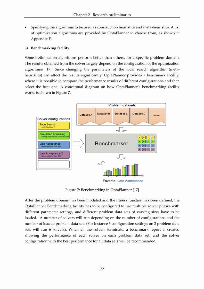
3) Benchmarking facility
Some optimization algorithms perform better than others, for a specific problem domain.
The results obtained from the solver largely depend on the configuration of the optimization
algorithms [17]. Since changing the parameters of the local search algorithm (meta-
heuristics) can affect the results significantly, OptaPlanner provides a benchmark facility,
where it is possible to compare the performance results of different configurations and then
select the best one. A conceptual diagram on how OptaPlanner’s benchmarking facility
works is shown in Figure 7.
Figure 7: Benchmarking in OptaPlanner [17]
After the problem domain has been modeled and the fitness function has been defined, the
OptaPlanner Benchmarking facility has to be configured to use multiple solver phases with
different parameter settings, and different problem data sets of varying sizes have to be
loaded. A number of solvers will run depending on the number of configurations and the
number of loaded problem data sets (For instance 3 configuration settings on 2 problem data
sets will run 6 solvers). When all the solvers terminate, a benchmark report is created
showing the performance of each solver on each problem data set, and the solver
configuration with the best performance for all data sets will be recommended.

23
3 Interplay between jBPM, Drools and
OptaPlanner
In this chapter, the interactions between the three projects (jBPM, Drools and
OptaPlanner) are described. Since the jBPM project is built on top of the Drools project, i.e.
the jBPM workflow engine is merged with the Drools rule engine, we need to learn how
they interact and how rules can be used when designing business processes. This interaction
between jBPM and Drools is explained in Section 3.1.
In Section 3.2, the integration between jBPM and OptaPlanner is described. This integration
is useful when assigning specific resources to manage specific process instances.
3.1 Integrating Drools Rules in jBPM processes
The workflow engine in jBPM is useful for automating the flow of activities in a business
process. By using a process modeling language such as BPMN2, we can define the sequence
of activities that need to be executed so as to achieve a specific business goal. Next we have
to decide on how to represent the business logic within those activities. One approach is to
define the business logic in a declarative manner by using business rules. Then a rule engine
could be used to evaluate different business situations and make automatic decisions based
on the information available. [14].
In order to allow the interaction between the jBPM workflow engine and the Drools rule
engine, a session has to be created. There are two types of sessions that can be created – a
stateless session which does not maintain the state or context between interactions (i.e. it
does not keep information from previous calls) and a stateful session which maintains the
state and keeps information from various calls and interactions. Additionally a session is
created based on a knowledge base, which is a container for the compiled knowledge assets
(rules, processes, etc.) [15].
Thus to create a session, a knowledge base has to be created first, then all the required
knowledge assets (process definitions, rules, etc.) have to be loaded and only then can a
session be instantiated. Typically long running business processes that involve various
human actors are defined in a stateful session. Then from these business processes, we can
interact with the rule engine in two ways – a stateless manner or a stateful manner. The
interaction with the rule engine in a stateless and stateful manner is described in Section
3.1.1 and Section 3.1.2 respectively.

Chapter 3 Interplay between jBPM, Drools and OptaPlanner
24
3.1.1 Stateless Interaction with the Drools rule engine
Interacting with the Drools rule engine in a stateless manner can be done when an activity
within the business process calls the rule engine to evaluate a set of business rules to
perform some complex calculations or data validations or to make some business decisions.
In such situations, the information required by the rule engine should be gathered and
prepared to be sent, communication problems between the process engine and the rule
engine should be dealt with and the data structures involved when the two platforms
(Drools and jBPM) interact should be managed [15].
This stateless type of interaction with the Drools rule engine to evaluate some business logic
can be done using a Business Rule Task node in the process definition. The information
which the rule engine requires has to be sent by specifying the Data Input Set and Data
Output Set parameters of the Business Rule Task node. Normally the information
interchanged in this type of interaction involves complex data structures like a graph of
objects. The classes (with their associated attributes/properties, getters and setters) from
which these objects are instantiated, can be created by using the web based data modeler.
Now while designing the process, we have to import this class and create an instance of it.
This object instance is used in the parameters (Data Input Set and Data Output Set) of the
Business Rule Task node. By using such a node in the process definition, we are implicitly
creating a stateless session, that exposes an execute() method, that internally inserts all facts
provided as parameters [15]. Additionally, another parameter called the RuleFlow Group
must be specified, so that the rule engine knows which group of rules must be evaluated,
when this node is reached. The rule engine will then evaluate the facts against the rules and
calls the fireAllRules() method when a match is found. Firing the rule will result in the
execution of the consequence of the rule. Then the result is returned back to the process
engine and then the stateless session is disposed. Figure 8 shows a business rule task node,
along with its core properties which include the Data Input Set, Data Output Set and the
Rule Flow Group.
Figure 8: Business Rule Task node and its core properties
Figure 9 shows a business process defined in a stateful session and two Business Rule task
nodes used within the process definition. In this kind of integration, the rule engine is

Chapter 3 Interplay between jBPM, Drools and OptaPlanner
25
considered just an external component, where a data object is sent and an immediate
response is expected. The data objects are inserted as facts that are evaluated against rules
by the rule engine. When an activation (rule match) is found, the consequence of the rule is
executed which may modify the data object. This execution cycle (rule engine’s working
execution) is run only once and then the control passes on to the next activity within the
process definition [29]. This is a rather encapsulated usage of the business rule service, or a
stateless interaction with the rule engine, where the context cannot be reused to add more
information later on.
Figure 9: Stateless interaction with the Drools rule engine (adapted from [36])
3.1.2 Stateful interaction with the Drools rule engine
It is also possible to interact with the rule engine in a stateful manner. However this stateful
interaction with the rule engine cannot be done directly from the KIE workbench. It can be
done from a java project/application where the process engine and rule engine is embedded.
Then as soon as a process instance is created, statements can be written to insert the process
instance as a fact into the rule engine. By doing this, we can make inferences on all
contextual information [14], [29]. In the previous case (i.e. the stateless context), we could
only make inferences on those data objects which were inserted as facts provided as
parameters to the Business Rule Task node. Additionally if multiple process instances are
executed under the same session, rules could be written to analyze those instances and make
global decisions about them.
Chapter 3 Interplay between jBPM, Drools and OptaPlanner
26
Figure 10: Stateful interaction with the Drools rule engine
Now when interacting with the rule engine in a stateful context (as shown in Figure 10),
when we issue the command to insert the process instance as a fact, data contained in the
process will be matched against the rules and those rules whose conditional section
evaluates to a true will be activated. These activations will be placed in an Agenda and
remains there until a method to fire the rules is called. Now if we want the same behavior as
in the previous case (Figure 9), the fireAllRules method must be called after the activities
(Task 1 and Task 2). However it is possible to put the rule engine in a reactive mode, thereby
forcing it to fire as soon as activations are created, without the need to explicitly call the
method to fire the rules [15].
The rule engine can be put in the reactive mode by adding Process Event Listeners and Agenda
Event Listeners in the application code. These event listeners allow us to get internal engine
events and execute actions (such as firing all rules) when these events are triggered. For
instance, the Process Event Listener has methods like beforeNodeTriggered, afterNodeTriggered,
afterProcessStarted whose behavior can be overridden and made to fire rules. Similarly the
Agenda Event Listener has methods which can be overridden to fire rules as soon as
activations are created. These methods provided by the event listeners are used as hook
points to define custom behavior [15].
3.2 Integrating OptaPlanner in jBPM
In this thesis, the concept of custom work items, also called custom service nodes or domain
specific nodes is used for the integration of OptaPlanner in jBPM.
The Service Task activity defined in the BPMN 2.0 specification, allows for the interaction
with external services in a generic manner. This service task concept can be used as an

Chapter 3 Interplay between jBPM, Drools and OptaPlanner
27
extension to plug in domain specific behavior and to handle external interactions. In jBPM,
the concept of a work item is used as an extension point to execute these external
interactions, by providing the process engine with a custom block/task representing custom
behavior. A work item will then represent a unit of work that is executed outside the process
engine’s scope [15]. In order to create a work item, we must first create a work item
definition and then create a work item handler which is explained in the next sections.
3.2.1 Creating a work item definition
When creating such a domain specific node, the data associated with the node must be
separated from the procedure on how to handle it. This means that the domain specific node
should be declarative and at a higher level of abstraction, i.e. it should not contain any code
[25]. This high level definition of the node (called a work item definition) must be created, so
that its runtime requirements can be interpreted by the process modeler and thereby
allowing users to set parameters as part of the process model. This work item definition is
created using the MVEL [37] expression language format. It can include fields such as the
name of the domain specific node, its input parameters and output results. There are also
fields to customize the graphical representation of these domain specific nodes such as a
display name and an icon field where an image can be uploaded [25]. Then this newly
created work item has to be registered with the jBPM engine for it to be visible in the palette
of the graphical modeler. This can be done by creating a file with a ‘.wid’ extension where
the work item definitions will reside and then linking it to the process engine’s
configuration.
3.2.2 Creating a work item handler
The execution of the work item is the responsibility of the work item manager in the process
engine, which in turn delegates this responsibility to a custom work item handler [25]. The
work item handler will execute the work item and then sends a completion notice to the
Work Item Manager. This Work Item Handler is a java class that implements the
WorkItemHandler interface, and defines two methods, one to execute the work item and the
other to abort the work item. The method responsible for the execution of the work item will
contain the necessary logic to call the external service. While the method to abort the work
item is responsible for cancelling the external interaction when there is a runtime failure or
an explicit cancellation is required [25]. It is in the execution method of the Work Item
Handler, where the OptaPlanner project will be called. This working execution of the work
item handler is conceptually represented in Figure 11. Finally a work item handler must be
mapped to their respective work item definition.
Chapter 3 Interplay between jBPM, Drools and OptaPlanner
28
Figure 11: Execution of a work item (adapted from [15])
3.2.3 OptaPlanner work item
The OptaPlanner work item created for this project is used to invoke a specific OptaPlanner
project. We do not create fields for the input parameters and output results for the
OptaPlanner node when defining the OptaPlanner WorkItem. This is because the problem
data set required for the OptaPlanner project is retrieved from a database and similarly the
output solution is put into a database. The database from where OptaPlanner retrieves the
problem data set is the same as the one where jBPM has been configured to persist run time
data. Additionally the database in which OptaPlanner stores the output solution can be
accessed from script tasks within jBPM processes.
The same concept can be used if we wanted to create any other OptaPlanner project and
integrate it with jBPM.

29
4 Case Description
In order to demonstrate how a process in jBPM can be integrated with an
OptaPlanner project and to show the various ways in which Drools rules can be used within
the jBPM process, a simple case describing a healthcare process is introduced in this chapter.
This case description is a simplified version of the skin cancer treatment process, based on
the research conducted by [27] in the dermatology oncology outpatient clinic at the
Catharina hospital, located in Eindhoven. The case is further modified to comprise of a
planning problem.
The process starts when patients arrive at a clinic and registers with a secretary at the front
desk. Here necessary details of the patient (name, age, medical history, problems, etc.) are
recorded. Then the patient has a consultation meeting with a doctor who reviews the patient
details and checks up on the patient to make an initial evaluation. The next step involves a
biopsy, where a tissue sample of the patient is taken by a nurse and has to be transported to
the pathology lab. Tissue samples are sent as a batch to the pathology department where
they are assigned to pathologists.
The assigned pathologist then performs a macroscopic study of the sample tissue, followed
by freezing, cutting and staining the sample. Then a diagnosis is done and a pathology
diagnosis report is sent to a doctor. The results from pathology are used by the doctor, to
verify symptoms/conditions of the patient and to give a final diagnosis, and thereby
identifying the type of skin cancer – Basal Cell Carcinoma (BCC), Melanoma or Squamous
Cell Carcinoma (SCC). Once the type of skin cancer has been identified, the appropriate
treatment procedure must be carried out by a specialist. Then post treatment and control
checks are performed by a nurse.
A flow chart depicting the control flow for the described process is shown in Figure 12.
Figure 12: Flow chart of the skin cancer treatment process

Chapter 4 Case Description
30
The different roles involved for this skin cancer treatment process is shown in Table 1 along
with the number of resources available and the tasks that they are responsible for.
Table 1: Roles involved in skin cancer treatment process
Role Resources
available Activities performed
Secretary 5 Register patient details
Doctor 8
Consultation Meeting :
- Perform initial check up
Receive pathology results and give diagnosis
Nurse 6 Biopsy :
- Collect tissue sample and fill pathology study request
Pathologist 5
Check pathology :
- Study sample specimen
- Cut and stain sample
- Create diagnosis report
Specialist 7
BCC treatment procedure
Melanoma treatment procedure
SCC treatment procedure
Let us further assume during the biopsy step, the tissue sample is assigned a specific
identification number, problem type and also a required amount of time needed by a
pathologist to study the sample. Additionally each problem type is associated with a specific
complexity value. When multiple tissue samples are collected, it is sent as a batch to the
pathology lab where they are distributed to pathologists. Every pathologist can solve only
specific problems types according to their skill or capability level, and they also have a
specific period of time when they are available. These tissue samples should be assigned to
the pathologists in a fair manner, while considering the complexity involved in studying the
sample and the fact that all samples assigned should fit within the pathologist’s available
time duration and capability /skill set.
This part of the case can be identified as a planning problem, and will be difficult for an
individual to manually come up with a resource allocation plan. This specific part of the
planning problem can be solved using the OptaPlanner framework, so as to correctly assign
pathologist to analyze specific tissue samples of patients. In the next chapter, we will first
solve this planning problem as a standalone project and then later integrate it within the
process modeled in jBPM. To demonstrate the interactions between jBPM, Drools and
OptaPlanner, the skin cancer treatment process will be divided into two parts as shown in
Figure 13. One part to show how jBPM can interact with OptaPlanner, and the second part
to show the various ways in which Drools rules can be used within the jBPM process.

Chapter 4 Case Description
31
Figure 13: Splitting the skin cancer treatment process into two parts
32
5 Applying the integration of KIE
projects on the case
In the previous chapter, we introduced a simple case which was divided into two
parts. The first part of the case comprised of a planning problem where tissue samples of
patients should be assigned to pathologists based on specific constraints. In this chapter, we
will first give an overview of the planning problem in Section 5.1.1 and then solve the
problem using the OptaPlanner framework as a standalone project in Section 5.1.2. We will
then explain how this specific OptaPlanner project can be integrated with jBPM in Section
5.1.3. The second part of the case will be used to show the various ways in which Drools
rules could be used within the process modelled in jBPM as explained in Section 5.2.
5.1 Part 1 of case
5.1.1 Overview of the planning problem

Chapter 5 Applying the integration of KIE projects on the case
33
5.1.2 Applying the OptaPlanner Framework
Figure 14: Identifying the planning entity

Chapter 5 Applying the integration of KIE projects on the case
34
Figure 15: Main classes for the problem domain

Chapter 5 Applying the integration of KIE projects on the case
35
Figure 16: Implementing hard and soft constraints as rules in the Drools Rule Language
Figure 17: XML file showing the problem data set for 5 cases and 2 pathologists

Chapter 5 Applying the integration of KIE projects on the case
36
Figure 18: XML solver configuration

Chapter 5 Applying the integration of KIE projects on the case
37
5.1.3 Integrating OptaPlanner with jBPM
Figure 19: Assigning case specific details during the consultation and biopsy phase

Chapter 5 Applying the integration of KIE projects on the case
38

Chapter 5 Applying the integration of KIE projects on the case
39
Figure 20: Invoking OptaPlanner as a custom work item
Figure 21: Assigning pathologist to perform pathology process

Chapter 5 Applying the integration of KIE projects on the case
40
5.2 Part 2 of case
In this section the second part of the case will be modelled in jBPM with the help of Drools
rules.
5.2.1 Integrating Drools rules in jBPM
Although there can be a number of ways to integrate rules with processes, three approaches
used in this thesis are described in the following sections.
Approach 1- Rules to set decision variables
The control flow of a business process defines the execution order of different activities. A
process instance takes different paths defined in the business process through decision
nodes, also called gateways in BPMN. These decision nodes/ gateways use the values of
certain decision variables, in order to choose a certain path during the execution of the
business process.
One approach to combine rules with processes is to allow the rule engine to set the value of
these decision variables in response to specific conditions. In order to do this, a business
rule task node can be added in the process model before the gateway node. This business
rule node should be linked to a set of rules to be evaluated at runtime. Moreover the data
which is required for the evaluation of the conditional part of the rule and the data required
for the execution of consequence /action part of the rule must be explicitly provided to the
rule engine as input and output parameters in the business rule task node.
Figure 22: Rules setting decision variables
For instance, let us look at the second part of the case described earlier and depicted in
Figure 22 as a BPMN model. In the Receive Pathology results and give diagnosis human task
node, a doctor will verify the conditions (diagnosis) seen in the patient based on the
pathology results. Based on the diagnosis, a particular treatment procedure must be
selected.
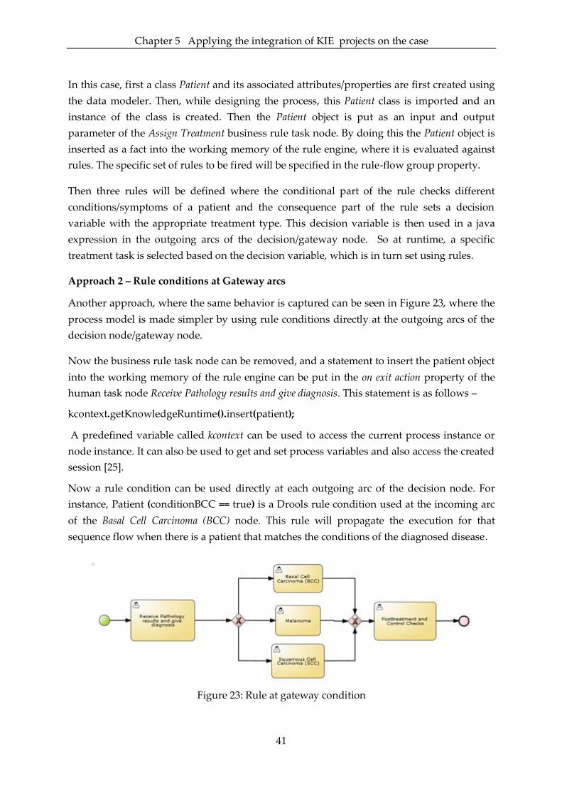
Chapter 5 Applying the integration of KIE projects on the case
41
In this case, first a class Patient and its associated attributes/properties are first created using
the data modeler. Then, while designing the process, this Patient class is imported and an
instance of the class is created. Then the Patient object is put as an input and output
parameter of the Assign Treatment business rule task node. By doing this the Patient object is
inserted as a fact into the working memory of the rule engine, where it is evaluated against
rules. The specific set of rules to be fired will be specified in the rule-flow group property.
Then three rules will be defined where the conditional part of the rule checks different
conditions/symptoms of a patient and the consequence part of the rule sets a decision
variable with the appropriate treatment type. This decision variable is then used in a java
expression in the outgoing arcs of the decision/gateway node. So at runtime, a specific
treatment task is selected based on the decision variable, which is in turn set using rules.
Approach 2 – Rule conditions at Gateway arcs
Another approach, where the same behavior is captured can be seen in Figure 23, where the
process model is made simpler by using rule conditions directly at the outgoing arcs of the
decision node/gateway node.
Now the business rule task node can be removed, and a statement to insert the patient object
into the working memory of the rule engine can be put in the on exit action property of the
human task node Receive Pathology results and give diagnosis. This statement is as follows –
kcontext.getKnowledgeRuntime().insert(patient);
A predefined variable called kcontext can be used to access the current process instance or
node instance. It can also be used to get and set process variables and also access the created
session [25].
Now a rule condition can be used directly at each outgoing arc of the decision node. For
instance, Patient (conditionBCC == true) is a Drools rule condition used at the incoming arc
of the Basal Cell Carcinoma (BCC) node. This rule will propagate the execution for that
sequence flow when there is a patient that matches the conditions of the diagnosed disease.
Figure 23: Rule at gateway condition

Chapter 5 Applying the integration of KIE projects on the case
42
Approach 3 – Dynamic composition of process fragments
In this approach, the actual process is split into process fragments during design time and
rules are used to compose/assemble them during execution or runtime [18].
The same example described previously is now split into five process fragments as shown in
Figure 24. During runtime, based on the conditions/symptoms seen in the patient, a specific
treatment process will be chosen. On completion of the treatment process, the next process
fragment will be chosen, which contains the Post treatment and Control Checks task.
For example, the Call Treatment Procedure business rule task node is linked to three rules. In
each rule, the conditional section evaluates the symptoms seen in the patient and the
consequence/action section starts a treatment process for that symptom. To do this, we need
to know the process ID (name of its process definition) and input data (Patient object) that
the process will require. Then this information can be used in a function to create a process
instance and then start the instance.
Figure 24: Dynamic composition of process fragments
5.2.2 Designing flexible processes using rules
In previous section, some approaches on how rules could be used while designing processes
was described. In this section, we will describe its relation to process flexibility.
Flexibility of a process has been defined as “the ability to deal with both foreseen and unforeseen
changes by varying those parts of the model which are affected by them, whilst retaining the essential
format of those parts that are not impacted by variations” [3]. In [3], the authors had presented the
taxonomy of flexibility, and distinguished between four types of flexibility for the control
flow perspective - (1) flexibility by design, (2) flexibility by deviation, (3) flexibility by under-
specification and (4) flexibility by change. In this thesis, rules have been used in the design
of business processes to achieve flexibility by design and flexibility by under-specification.
Flexibility by design is “the ability to incorporate alternative execution paths within a process
definition at design time, such that the selection of the most appropriate path can be made at run time
Chapter 5 Applying the integration of KIE projects on the case
43
for each process instance” [3]. This type of flexibility can be achieved, by using rule conditions
at the outgoing arcs of a decision node (or an XOR gateway) within the business process.
Then during runtime, the most appropriate execution path will be selected based on the
evaluation of the rule condition.
Flexibility by under-specification is “the ability to execute an incomplete process model at run-
time” [3]. This type of flexibility can be achieved, by using rules within a process to invoke
other processes. As explained earlier, this can be done by breaking apart the
standard/original model into independent process fragments and then dynamically
assembling them at runtime using rules. Here appropriate rules must be developed to select
a particular process fragment. This is useful in scenarios where the execution order of
different parts of the business process is not known in advance. It may also be useful in
special scenarios where certain process instances may require parts of the business process
to be omitted or additional parts to be inserted. This is a type of under-specification called
late binding, where a missing part of the model is linked to some pre specified functionality
at runtime [38].
44
6 Conclusions
This thesis started with addressing some issues inherent in WfMS that limits its
application in the healthcare domain, i.e. these systems fall short with regard to providing
flexibility and they do not deal with the planning and scheduling of healthcare resources.
One approach to designing flexible processes was to combine them with rules. Furthermore,
an approach to address the problem of resource allocation for healthcare processes was to
integrate them with an automated planning system. It was decided to use the KIE group of
open–source java projects developed by Red Hat JBoss community to overcome these
limitations. These projects include the jBPM business process management suite, the Drools
project for business rule management and OptaPlanner, a framework to solve planning
problems. Through previous chapters we have demonstrated how these projects can be used
together to support processes in healthcare.
In this chapter, the final conclusions of this thesis are presented. In Section 6.1, we first
discuss some works found from literature related to the main subject of this research, which
is followed by addressing the main research questions in Section 6.2. Then some of the
limitations of this research and some recommendations for future research are listed in
Section 6.3 and Section 6.4 respectively. Lastly, some commercial software products that are
similar to the projects belonging to the KIE group are described in Section 6.5.
6.1 Related Work
In this section, we first discuss some works from literature where rules have been used in
the design of flexible processes. Then we briefly describe an approach found from literature
on how to integrate a WfMS with a planning and scheduling system.
6.1.1 Integrating rules with processes
In [18], the authors had identified multiple patterns for integrating business rules with
business processes. They also explained how these patterns could be integrated in a service
composition language, like Business Process Execution Language (BPEL). Some of these
patterns are summarized in Table 2. The key common point for these patterns was that the
rules could be modified during the runtime of a process instance. This is similar to achieving
flexibility by change which is “the ability to modify a process model at runtime such that one or all
of the currently executing process instances are migrated to a new process model” [3]. However
achieving this kind of flexibility is currently not possible in jBPM. If any rule has been
modified or changed in jBPM, the process model has to be redeployed so that future process
instances can take note of the changes.

Chapter 6 Conclusions
45
Table 2: Patterns for integrating rules with processes (adapted from [18] [39])
Pattern Group Pattern Brief description
Control flow
decisions
Decision Logic
Abstraction
The decision logic is defined as business
rules
Decision node to
business rule
binding
The dynamic mapping of a decision node to
a business rule
Decision with
flexible input data
The rule can access any data within the
process, instead of explicitly providing the
data to the rule engine
Decision with
flexible output
Rules can be used to dynamically assign an
activity at the outgoing branch of a decision
node
Data constraints Constraints at
predefined
checkpoints
Rules can be used to validate constraints on
input and output data of an activity
Constraints at
multiple
checkpoints
Rules can be used to validate constraints on
data at multiple positions in a process
Dynamic process
composition
Rule based sub
process selection
Rules can be used to select a sub process
dynamically
Rule based process
composition
Rules can be used to dynamically assemble
process fragments
Additionally in [18], the authors had focused only on the implementation details when
integrating rules with processes and did not consider the modeling aspects. The modeling
aspects for these set of rule patterns were later investigated in [39], where the authors had
combined the R2ML (REWERSE Rule Markup Language) [40] and BPMN languages to
introduce a new rule-enhanced business process modeling language called rBPMN. The
metamodel for the rBPMN language involved elements from the BPMN metamodel and the
R2ML metamodel and some extensions such as rule gateway notation (a gateway with the R
symbol).

Chapter 6 Conclusions
46
6.1.2 Integrating automated planning and scheduling in processes
When considering WfMS that deal with the planning and scheduling of resources, one
interesting contribution found from literature was the work of [24]. Here the authors had
presented a generic design and implementation approach for integrating a WfMS with a
calendar-based scheduling facility. They first developed a conceptual model (Colored Petri
Net) using CPN tools which served as specification and simulation model for the schedule-
aware WfMS. The architecture of this schedule-aware WfMS mainly involved four loosely
coupled components – (1) a workflow engine which is responsible for routing cases within
the organization, (2) a workflow client application that provides a work-list management
component to allow users to select and perform tasks within a case, (3) a calendar where
appointments (of tasks to resources) are recorded, and (4) a scheduling service that provides
scheduling facilities to the system. The concrete realization of the system was done using the
YAWL workflow engine, Microsoft Exchange Server 2007 / Outlook which was the platform
for providing a calendar and allowing user interactions, and a scheduling service which was
implemented in Java.
A scheduling problem along with the scheduling constraints (for a case) was formulated as a
graph. The process definition of a case at a given state was mapped to this graph. The nodes
of the graph had properties such as the task name, duration of the task, roles involved for
executing the task, split/join semantics of the node, the state of the node (enabled/disabled),
etc. This scheduling problem could be sent to the scheduling service by the workflow engine
when any of the following situations occurred: when a case was started, when a task in the
case was finished, when a user would require an appointment to be rescheduled or even at
regular time intervals.
The scheduling service would then schedule tasks while considering the ordering sequence
of tasks in the process definition. Additionally if multiple roles were involved in the
execution of a task, the service would select a resource for each specified role. The
scheduling service will then book an appointment in the calendar of those resources
involved.
However, our work focused only on finding the best resource capable of handling a
particular case. To do this, we have integrated a specific OptaPlanner project within a
specific process in jBPM. The OptaPlanner project would solve a specific planning problem
and develop a resource allocation plan. Then the actor responsible for handling each case is
assigned based on the resource allocation plan.
Chapter 6 Conclusions
47
6.2 Research Questions
In this section, we will address the research question that was formulated in Section 1.4 -
How can the KIE group of open-source projects (namely Drools, jBPM and OptaPlanner)
be used to support processes in healthcare?
In order to use these projects, first various technical issues have to be overcome, mostly
regarding jBPM. Many problems have been identified during process modeling and
execution which have been documented in Appendix F3. For some of these problems, work
arounds have been suggested. Moreover some problems and limitations of the Business
Process Simulation capabilities provided by jBPM was also identified and documented in
Appendix B2. Critical errors such as incorrect semantics for BPMN notations during
simulations were reported to developers in the JBoss community [41]. Additionally, the
steps to be followed in order to assign roles and groups to users were not completely
specified in the jBPM 6 documentation. These steps are listed in Appendix F2.
Now to answer the main research question, the following three sub research questions had
to be answered -
1. How can Drools business rules be used to design flexible processes in jBPM?
Rules implemented in the Drools Rule Language can be used in the design of processes in
jBPM to achieve flexibility by design and flexibility by under-specification as
demonstrated in Section 5.2.1. Flexibility by design was achieved when rule conditions
were used at the outgoing arcs of XOR gateways. Additionally, since complex constraints
can be captured using rule conditions, the process model can be made simpler. Flexibility
by under-specification was achieved by using rules to invoke other processes. This was
done by breaking apart the original model into process fragments and then assembling
them at runtime using rules.
2. How can OptaPlanner be used to support the planning of healthcare resources?
Some of the common planning problems healthcare organization face involves allocation
of patients to doctors, allocation of beds to patients, allocation of shifts to nurses, logistics
of drugs, scheduling of ambulances and scheduling of operational theatres [20]. As such
these planning problems can be solved using the OptaPlanner framework. To do so, the
problem domain has to be modeled as a set of java classes with specific annotations (such
as the planning entity, planning variable, etc.). The constraints of the planning problem
can be represented as rules implemented in the Drools Rule Language. These rules will
be used by the Drools rule engine to calculate the score of every solution under
evaluation. A solver has to be configured to use an optimization algorithm (construction

Chapter 6 Conclusions
48
heuristics and meta-heuristics) for finding possible solutions. Then the solver is built
based on the configurations set. A data set representing the planning problem has to be
generated or retrieved from a data source (database, file system, etc.) and then it should
be loaded into the solver. Then the appropriate command to solve the problem has to be
issued, followed by retrieving the best solution found. This solution found will be the
resource allocation plan to be used.
In Chapter 4, a specific planning problem involving cases (patient tissue samples) which
are to be distributed to pathologists was introduced. This problem was then solved in
Section 5.1.2 using the OptaPlanner framework. Since the solver could be configured in a
number of ways, a benchmarking facility provided by OptaPlanner was also tried to find
a solver configuration which gives good performance results w.r.t the specific planning
problem.
3. Can these 3 projects (Drools, jBPM and OptaPlanner) be combined to offer a meaningful
interaction? If so, how do they interplay and what is the benefit of using all 3 at once, as
opposed to isolation?
Yes, it is possible to combine these 3 projects to offer a meaningful interaction. This was
demonstrated in Chapter 5, where OptaPlanner and Drools rules were used in jBPM
processes based on the case description introduced in Chapter 4. Further, the use of
Drools rules in OptaPlanner to represent constraints for a specific planning problem, was
shown in Figure 16 and explained in Appendix G.
Since the jBPM workflow engine is already merged to work with the Drools rule engine,
we only had to learn how they interact (i.e. in a stateless and a stateful manner) which
was explained in Section 3.1. Additionally, since the OptaPlanner project is also already
embedded with the Drools rule engine; we only had to learn how to define a fitness
function to calculate the score of a solution using the Drools Rule Language. There was
no previous work found where an OptaPlanner project was integrated with jBPM. For
this thesis, we used the concept of a domain specific node (or a custom work item) to
make this integration possible as explained in Section 3.2
Using all 3 projects at once provides the benefit of designing flexible processes and also
allows the integration of automated planning within the process. We have shown how
process flexibility for the control flow perspective can be achieved using Drools rules,
specifically how flexibility by design and flexibility by under-specification can be
achieved.
If Drools rules were not used within a process in jBPM, it would not be possible to
achieve flexibility by under-specification, i.e. during runtime, the dynamic assembling of
process fragments would not be possible.
Chapter 6 Conclusions
49
Additionally by allowing the Drools rule engine to perform score calculations within
OptaPlanner, we will be representing all the constraints of the planning problem as
separate rules in a single file with a ‘.drl’ extension. This gives us the flexibility to easily
add new constraints or update existing ones.
If the Drools rule engine was not used to perform the score calculations, then complex
scoring functions would have to be implemented using Java. Then a high maintenance
cost would be required if the scoring constraints change regularly. Additionally
implementing the score calculations using simple java would make the performance of
OptaPlanner slow and less scalable when there are a large number of solutions in the
search space [17].
The integration of OptaPlanner with jBPM allows us to use a resource allocation plan
during process execution. Then specific resources can be made responsible for managing
specific process instances based on the resource allocation plan.
If an automated planning system such as OptaPlanner was not used with jBPM, then a
manual resource allocation plan would have to be created and used.
6.3 Limitations
Some of the limitations of this thesis are described in this section.
1. For the first part of the case, which was used to demonstrate the integration of
OptaPlanner with jBPM, three disconnected process models were designed-
A process model representing the consultation phase and the biopsy phase.
A model representing the optimal allocation of cases to pathologists. It was in
this process model where the OptaPlanner project was invoked.
A model representing the pathology process, where pathologists were
assigned to study a specific case/tissue sample (based on a resource allocation
plan generated by OptaPlanner).
This division was done mainly because the appropriate modeling logic to group
tissue samples based on a batch size was not successful.
2. Currently whenever the OptaPlanner project is invoked from jBPM, it will retrieve
appropriate case (tissue sample) data of all the patients from the database and create
a resource allocation plan. This includes previously allocated cases as well. However,
it should be designed in such a way that it retrieves the batch of case data for new
arrivals only.
3. This thesis had only investigated using Drools rules to achieve flexibility at the
control flow perspective.
Chapter 6 Conclusions
50
4. This thesis did not investigate how OptaPlanner could be combined with the
simulation engine of jBPM. If such an integration was possible, then in scenarios
where the number of patients who arrive in the hospital increases. Then OptaPlanner
could be used to find an optimal resource allocation plan, which could be used as an
input to run simulations. Then it would be possible to find out if the hospital can
manage increasing demands of patients with the best allocation of resources.
6.4 Future Research
In this section, some possible directions for future research are presented:
1. Currently when invoking the OptaPlanner project from a process in jBPM, the
problem data set used by OptaPlanner is retrieved from databases. Future research
should focus on sending the problem data set as input parameters of the
OptaPlanner domain specific node, maybe as an array of objects.
2. For future research, additional constraints should be developed for the OptaPlanner
project, such as deadlines for work items/cases and the domain model should be
made richer by adding more classes (planning entities and problem facts).
3. The OptaPlanner project should be developed to be a continuous planner in such a
way that when a new batch of cases are to be assigned to resources, the new solution
should take into account the previous solution as well to ensure fair distribution. In
continuous planning, one or more upcoming planning windows will be solved at the
same time and then the process is repeated within a time interval (weekly, monthly).
Then the past planning windows should be fixed; however they may be used for
calculating the score of solutions involved in the upcoming planning window [17].
4. The KIE workbench should be extended to support the stateful interaction with the
Drools rule engine. Currently the stateful interaction with the rule engine can only be
done from a java project where the process engine and the rule engine is embedded.
5. Future research should focus on the use of Drools rules to achieve flexibility at the
data, resource and application perspectives as well.
6.5 Related Commercial Software
In this section, some commercial alternatives to the KIE projects (Drools, jBPM and
OptaPlanner) are described. For instance, one leading commercial BPM suite is IBM
Business Process Manager, which is available in three configurations (Express, Standard and
Chapter 6 Conclusions
51
Advanced) tailored to suit the needs of small, mid-sized and large organizations. Some of its
notable feature includes support for BPMN and BPEL standards, a unified asset repository
and a control center for governing the entire BPM lifecycle [42]. This is similar to jBPM,
which supports the BPMN and BPEL standards, has a single repository where various types
of knowledge assets can be stored and a single workbench from where processes can be
authored, executed, managed and monitored.
However some features which jBPM does not support when compared to the IBM Business
Process Manager include a Process Optimizer to detect performance bottlenecks based on
historical data, and then visualizing it through ‘hot-spots’ on the process diagram, easy
access to any Enterprise Content Management System, integration with SAP systems,
process design and application use through mobile platforms. Additionally, IBM’s Business
Process Manager also has an in-built Performance Data Warehouse that provides business
activity monitoring (BAM) capabilities through process status maps, dashboards and service
level agreement alerts [42]. In contrast, the jBPM’s BAM module only supports creating
dashboards for viewing key performance indicators of the business process. Moreover,
IBM’s BPM offering can be offered as a subscription based cloud service as well [42].
Other products of IBM include Operational Decision Manager (ODM) which is a
comprehensive platform for business rule management [43]. A project similar to
OptaPlanner is IBM ILOG CPLEX Optimization Studio which is an analytical decision
support toolkit for developing optimization models. It is embedded with two optimization
engines (one for mathematical programming and the other for constraint programming)
used for solving planning and scheduling problems. These problems are modeled using the
Optimization Programming Language (OPL) provided by IBM [44]. This software product is
not integrated with the IBM’s BPM offering.
Another well recognized commercial BPM suite is provided by Appian. Besides the core
BPM functionality provided, it also focuses on the use of cloud and mobile computing
platforms to create a configurable and interconnected process management environment
[45]. Additionally Appian BPM suite is integrated with live data streams from various social
networks and also supports dynamic adaptation to process changes (i.e. modifying running
process instances on the fly) [46]. None of these features are supported by jBPM at the
moment.
Another well-established vendor in the BPM market is Pegasystems, that provides software
for creating sophisticated, dynamic process applications with advanced case handling and
analytics features. It has also extended its core capabilities with mobile and social
technologies [45]. Such features are currently not supported by jBPM.
However most of these features provided by commercial BPMS are in the development
roadmap for future versions of jBPM such as [47]:

Chapter 6 Conclusions
52
Simulation replay – which will support scenarios for simulation based on information
from history logs
BPM projects in the cloud
BPM connectors and adapters to extend how the engine can integrate with external
services
Dynamic processes - to change running process instances on the fly. This is similar to
achieving flexibility by change.
User interfaces to support mobile users to participate in processes or monitor them
Case handling
Tools to support the migration of running process instances to new process definitions
Process mining
53
References
[1] Institute of Medicine, "Crossing the Quality Chasm: A New Health System for the 21st
Century," Academies Press, Washington, DC, 2001.
[2] Deloitte Touche Tohmatsu Limited, "2014 Global health care outlook Shared
challenges,shared opportunities," 2014.
[3] R. Mans, W. M. P. van der Aalst, N. Russell and P. Bakker, "Implementation of a
healthcare process in four different workflow systems," Eindhoven, 2009.
[4] W. Yao and A. Kumar, "CONFlexFlow: Integrating Flexible Clinical Pathways into
Clinical Decision Support Systems using Context and Rules," Decision Support Systems,
vol. 55, no. 2, p. 499–515, May 2013.
[5] S. Graeber, S. Richter, J. Folz, P. Pham, P. Jacob and M. K. Schilling, "Clinical Pathways
in General Surgery - Development, Implementation, and Evaluation.," Methods of
Information in Medicine, vol. 46, no. 5, pp. 574-579, 2007.
[6] R. Blaser, M. Schnabel, C. Biber, M. Bäumlein, O. Heger, M. Beyer, E. Opitz, R. Lenz and
K. A. Kuhn, "Improving pathway compliance and clinician performance by using
information technology," International Journal of Medical Informatics, vol. 76, no. 2, pp.
151-156, 2007.
[7] M. Reichert, "What BPM Technology Can Do for Healthcare Process Support," in 13th
Conf. on Artificial Intelligence in Medicine (AIME'11), Bled, Slovenia, 2011.
[8] M. D. Rodriguez-Moreno, D. Borrajo, A. Cesta and A. Oddi, "Integrating planning and
scheduling in workflow domains," Expert Systems with Applications, vol. 33, no. 2, p. 389–
406, 2007.
[9] F. S. Hsieh, "Context-aware Workflow Driven Resource Allocation for e-Healthcare," in
Proceedings of 9th International Conference on e-Health Networking, Application and Services,
Taipei, 2007.
[10] J. Xu, C. Liu and X. Zhao, "Resource Planning for Massive Number of Process
Instances," in On the Move to Meaningful Internet Systems: OTM 2009, Springer Berlin
Heidelberg, 2009, p. 219–236.
54
[11] P. Nie, R. Seppälä and M. Hafrén, "Open Source Power on BPM - A Comparison of
JBoss jBPM and Intalio BPMS," 2008.
[12] AVIO Consulting, "BPM Product Analysis, A Comparison of IBM Business Process
Manager and Oracle BPM," Oracle, October 2013. [Online]. Available:
http://www.oracle.com/us/technologies/bpm/ibm-bpm-comparison-2046800.pdf.
[13] P. Wohed, B. Andersson, A. H. M. ter Hofstede, N. Russell and W. M. P. van der Aalst,
"Patterns-based evaluation of open source BPM systems: The cases of jBPM, OpenWFE,
and Enhydra Shark," Information and Software Technology, vol. 51, no. 8, p. 1187–1216,
2009.
[14] P. Harmon, "Exploring BPMS with Free or Open Source Products," 31 July 2007.
[Online]. Available: http://www.bptrends.com/publicationfiles/advisor200707311.pdf.
[15] M. Salatino and E. Aliverti, jBPM5 Developer Guide, Birmingham: Packt Publishing,
2012.
[16] Red Hat JBoss Drools Team, "Drools Documentation," 20 December 2013. [Online].
Available: http://docs.jboss.org/drools/release/6.0.1.Final/drools-
docs/html_single/index.html.
[17] Red Hat JBoss OptaPlanner Team, "OptaPlanner User Guide," 20 December 2013.
[Online]. Available: http://docs.jboss.org/drools/release/6.0.1.Final/optaplanner-
docs/html_single/index.html.
[18] T. Graml, R. Bracht and M. Spie, "Patterns of business rules to enable agile business
processes," Enterprise Information Systems, vol. 2, no. 4, pp. 385-402, 2008.
[19] W. M. P. van der Aalst, M. Weske and D. Grunbauer, "Case handling: a new paradigm
for business process support," Data & Knowledge Engineering, vol. 53, no. 2, pp. 129-162,
2005.
[20] C. Spyropoulos, "AI planning and scheduling in the medical hospital environment,"
Artificial Intelligence in Medicine, vol. 20, no. 2, p. 101–111, 2000.
[21] J. Xu, C. Liu, X. Zhao and S. Yongchareon, "Business Process Scheduling with Resource
Availability Constraints," in On the Move to Meaningful Internet Systems: OTM 2010,
Springer Berlin Heidelberg, 2010, pp. 419-427.
[22] P. M. Berry and B. Drabble, "SWIM: An AI-based System for Organizational
Management," in Proceedings of the 2nd NASA international workshop on planning and

55
scheduling for space, San Francisco, 2000.
[23] S. Goldmann, J. Munch and H. Holz, "Distributed process planning support with
MILOS.," International Journal of Software Engineering and Knowledge Engineering,, vol. 10,
no. 4, pp. 511-525, 2000.
[24] R. Mans, N. Russell, W. van der Aalst, A. Moleman and P. Bakker, "Schedule-Aware
Workflow Management Systems," in Transactions on Petri Nets and Other Models of
Concurrency IV, vol. 6550, Springer Berlin Heidelberg, 2010, pp. 121-143.
[25] Red Hat JBoss jBPM Team, "jBPM Documentation," 20 November 2013. [Online].
Available: http://docs.jboss.org/jbpm/v6.0.1/userguide.
[26] Stack Overflow, "Integrate jBPM with OptaPlanner," 29 April 2014. [Online]. Available:
http://stackoverflow.com/questions/23372089/integrate-jbpm-with-optaplanner.
[27] H. L. Romero, N. P. Dellaert, S. v. d. Geer, M. Frunt, M. H. Jansen-Vullers and G. A. M.
Krekels, "Admission and capacity planning for the implementation of one-stop-shop in
skin cancer treatment using simulation-based optimization," Health Care Management
Science, vol. 16, no. 1, pp. 75-86, 2013.
[28] X. Feng and M. Subramanian, "Incorporating Business Rule Engine Technology in
Control Center Applications," in IEEE Energy2030, Atlanta, 2008.
[29] T. Meservy, C. Zhang, E. T. Lee and J. Dhaliwal, "The Business Rules Approach and Its
Effect on Software Testing," Software, IEEE, vol. 29, no. 4, pp. 60-66, 2012.
[30] T. D. McFarland and R. Parke, Expert Systems in Education and Training, New Jersey:
Educational Technology, 1990, pp. 57-66.
[31] K. Desai, D. Hoffman, E. Kopalova and D. L. Sage, "Red Hat JBoss BPM Suite 6.0
Development Guide," 2014. [Online]. Available:
https://access.redhat.com/documentation/en-
US/Red_Hat_JBoss_BPM_Suite/6.0/html/Development_Guide/index.html.
[32] W. M. P. van der Aalst, A. H. M. ter Hofstede and M. Weske, "Business Process
Management: A Survey," in Business Process Management, Springer Berlin Heidelberg,
2003, pp. 1-12.
[33] W. M. P. van der Aalst, "Business Process Management: A Comprehensive Survey,"
ISRN Software Engineering, p. 1–37, 2013.
56
[34] C. P. Gomes, "Artificial Intelligence and Operations Research: challenges and
opportunities in planning and scheduling," Knowledge Engineering Review, vol. 15, pp. 1-
10, 2000.
[35] R. Barták, M. A. Salido and F. Rossi, "Constraint satisfaction techniques in planning and
scheduling," Journal of Intelligent Manufacturing , vol. 21, no. 1, pp. 5-15.
[36] M. Salatino, "(PROCESSES & RULES) OR (RULES & PROCESSES) 3/X," 29 July 2012.
[Online]. Available: http://salaboy.com/2012/07/29/processes-rules-or-rules-processes-
3x/.
[37] M. Brock, M. Proctor, B. McWhirter and P. Lalloni, "MVEL Java-based expression
language," Codehaus, [Online]. Available: http://mvel.codehaus.org/.
[38] M. Adams, A. H. M. ter Hofstede, M. Pesic, H. Schonenberg and W. M. van der Aalst,
"Flexibility as a Service," in Database Systems for Advanced Applications, vol. 5667,
Springer Berlin Heidelberg, 2009, pp. 319-333.
[39] M. Milanovi, D. Gaševi and L. Rocha, "Modeling Flexible Business Processes with
Business Rule Patterns," in Enterprise Distributed Object Computing Conference (EDOC),
2011 15th IEEE International, Helsinki, 2011.
[40] REWERSE Rule Markup Language, [Online]. Available: http://oxygen.informatik.tu-
cottbus.de/rewerse-i1/?q=node/6.
[41] RedHat JBoss Community, "Pathfinder in jBPM 6 Simulation showing extra paths," 31
March 2014. [Online]. Available: https://community.jboss.org/thread/237694.
[42] IBM, "Dramatically improve the way work gets done with IBM Business Process
Manager," 2012. [Online]. Available: http://www-
03.ibm.com/software/products/en/business-process-manager-express.
[43] IBM, "What’s New in IBM Operational Decision Manager V8.5," [Online]. Available:
http://www-01.ibm.com/software/websphere/subscriptionandsupport/compare-odm-
versions.html.
[44] IBM, "Detailed Scheduling in IBM ILOG CPLEX Optimization Studio with IBM ILOG
CPLEX CP Optimizer," 2010. [Online]. Available: http://www-
03.ibm.com/software/products/en/ibmilogcpleoptistud/.
[45] N. Ward-Dutton, "BPM technology review 2013:Vendor comparison report," MWD
Advisors 2013 .

57
[46] Appian Corporation, "Appian BPM Suite Version: 5.7," 2009. [Online]. Available:
http://www.bptrends.com/publicationfiles/07-09-
Appian%20BPMSuite%20Ver.%205.7%20_3_-Malcolm1.pdf.
[47] RedHat JBoss, "jBPM Roadmap," [Online]. Available: http://jbpm.jboss.org/roadmap.
[48] M. Proctor, "Drools & jBPM," 28 June 2009. [Online]. Available:
http://blog.athico.com/2009/06/drools-reflection-on-5-years.html.
[49] J. Davis, Open Source SOA, Greenwick: Manning Publications Co., 2009.
[50] Red Hat JBoss, "jBPM5 tutorial - introduction," [Online]. Available:
http://www.mastertheboss.com/jbpm5/jbpm5-tutorial-introduction.
[51] "BPMN tutorial," [Online]. Available: http://www.bpmn-tool.com/en/tutorial/.
[52] T. Surdilovic, "Business Process Simulation in jBPM Designer," 14 September 2012.
[Online]. Available: http://blog.athico.com/2012/09/business-process-simulation-in-
jbpm.html.
[53] M. Salatino, "(PROCESSES & RULES) OR (RULES & PROCESSES) 1/X," 19 July 2012.
[Online]. Available: http://salaboy.com/2012/07/19/processes-rules-or-rules-processes-
1x/.
[54] M. Milanovic, D. Gasevic and L. Rocha, "Modeling Flexible Business Processes with
Business Rule Patterns," in The 5th IEEE International Enterprise Distributed Object
Computing Conference (EDOC 2011), Helsinki, 2011.

58
Appendix A. History of Drools, jBPM, OptaPlanner
The first works on the Drools rule engine was initiated by Bob McWhirter in 2001, and was
based on a brute force linear search approach. However due to the limitations of this
approach, Drools 1.0 was not released. The next version Drools 2.0 was released in June
2005, where the rule engine used a partial implementation of the Rete algorithm for pattern
matching, and rules were written in XML scripting language. By October 2005, the Drools
project was incorporated into the JBoss Enterprise Middleware Suite (JEMS) and the project
was led by Mark Proctor. A year later, in 2006 JBoss was acquired by Red Hat, Inc. and
many of the features from the JBoss community projects were integrated into enterprise-
class middleware software products. In June 2006, Drools 3.0 was released and included a
full implementation of the Rete algorithm. Moreover this version introduced the ‘.drl’
format, specifically for writing rules in the Drools Rule Language. By July 2007, Drools 4.0
was released, with major performance improvements for the rule engine, and more
significantly, a business rule management system functionality was added [48], [49].
The next big release, Drools 5.0 was in 2009, which introduced the Business Logic
integration Platform which provided a unified and integrated platform for Rules, Workflow
and Event Processing. This platform included 5 main modules- Drools Expert (the rule
engine itself), Drools Guvnor (the business rule management system), Drools Fusion (the
module for complex event processing) and Drools Flow (providing workflow capabilities). It
also included a module called Drools Solver which used search and optimization algorithms
combined with Drools Expert (the rule engine) for solving planning problems [48].
The first official release of the jBPM project was in early 2004, followed by the 2.0 release
later in the year. During the same period, the jBPM project was introduced into the JBoss
family of products. The next version jBPM 3.0 was released in 2005, where the workflow
engine supported the jBPM Process Definition Language (jPDL) and also introduced a web
based console, which provided an easy to use graphical interface for managing processes
and instances. In jBPM 4, the workflow engine was made to support jPDL as well as the
BPMN 2.0 standard specification for creating process models [49], [50].
In February 2011, the 5th version of jBPM was released, where the workflow engine was
integrated with the Drools rule engine. The jBPM 5 project inherited the code from Drools
Flow project and Drools Expert. It also included the monitoring and management of
processes through a web based console. BPMN 2 was used as the process definition
language, which standardizes the visual representation of modeling notations for creating
business processes, as well as their underlying XML representation [47], [50].
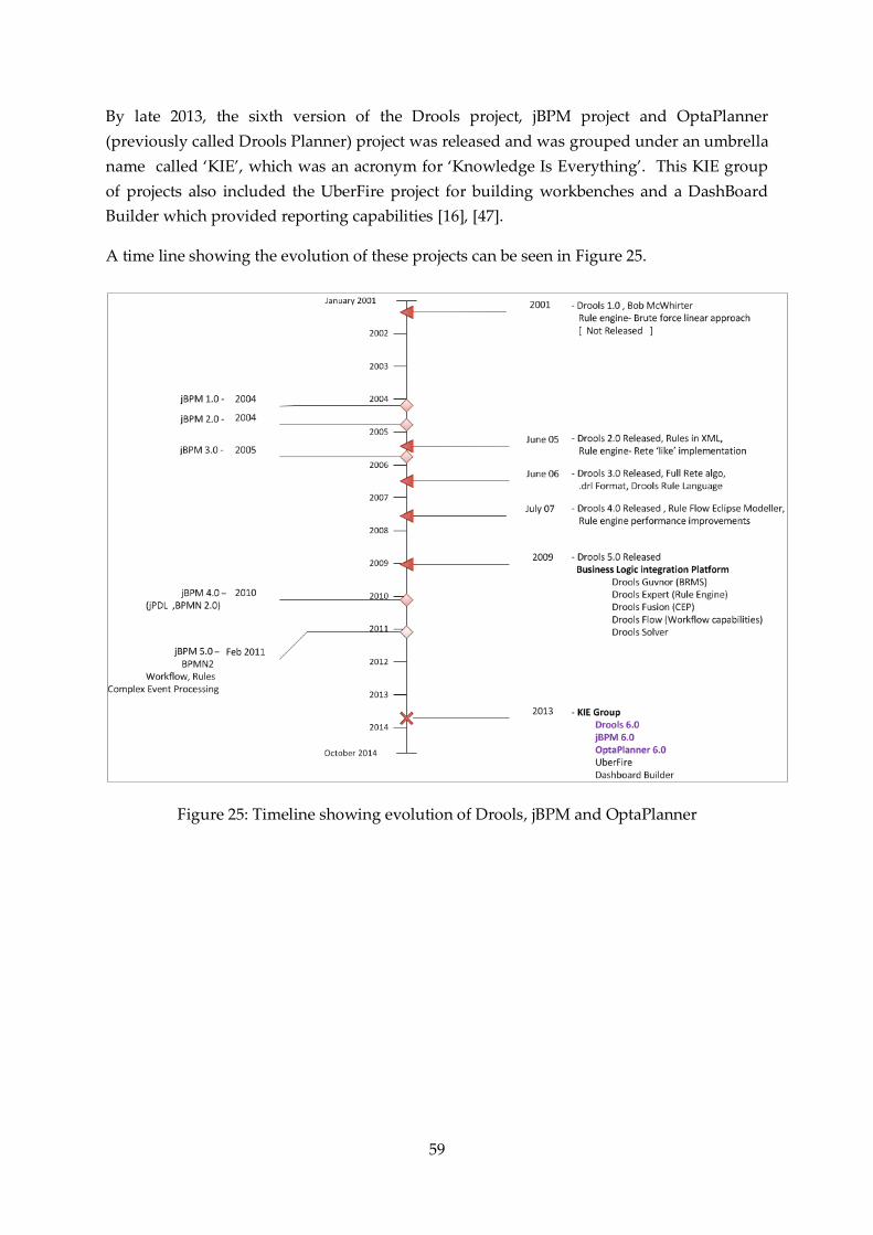
59
By late 2013, the sixth version of the Drools project, jBPM project and OptaPlanner
(previously called Drools Planner) project was released and was grouped under an umbrella
name called ‘KIE’, which was an acronym for ‘Knowledge Is Everything’. This KIE group
of projects also included the UberFire project for building workbenches and a DashBoard
Builder which provided reporting capabilities [16], [47].
A time line showing the evolution of these projects can be seen in Figure 25.
Figure 25: Timeline showing evolution of Drools, jBPM and OptaPlanner

60
Appendix B. BPMN 2.0 Notations
B.1. BPMN 2.0 notations supported in jBPM 6
A list of the various BPMN 2.0 notations supported by jBPM can be seen in Table 3, along
with their description [51] and those notations present in jBPM 5 as well.
Table 3: BPMN 2.0 notations supported in jBPM 6
Tasks
User
A User Task is performed by a human actor with the assistance of a
software application and is scheduled through a task list manager.
jBPM 5 check
Send-
A Send Task is used to send a message to an external participant.
jBPM 5 check
Receive
A Receive Task is used to wait for a message to arrive from an external
participant.
jBPM 5 check
Manual
A Manual Task is to be performed without the aid of the business
process execution engine or any application.
jBPM 5 check
Service
A Service Task relies on an external Web service or an automated
application for completing its unit of work.
jBPM 5 check
Business Rule
A Business Rule Task provides a mechanism for the process to provide
input to a Business Rules Engine and to get the output of calculations
that the Business Rules Engine might provide.
jBPM 5 check
Script
A Script Task is an automatic task in which a script is executed by the
process engine.
jBPM 5 check
Sub Processes
Reusable
The reusable sub process is used to invoke another process through the
‘Called Element ’property.
jBPM 5 check
Multiple Instances
A multiple instance sub process contains process segments that can be
executed multiple times.
jBPM 5 check

61
Embedded
An embedded sub process acts a container for a process segment. It
must contain a process with a start and end node.
jBPM 5 check
Ad-Hoc
An ad-hoc sub process contains a group of tasks that does not require a
sequenced relationship.
jBPM 5 check
Event
An event sub process is placed within another sub process. It becomes
active when its start event gets triggered and can interrupt the sub
process context or run in parallel (non-interrupting), depending on
the start activity.
Start Events
None
Un-typed start event that triggers a new process instance.
jBPM 5 check
Message
The start of a process is triggered when a message is received from
another process.
jBPM 5 check
Timer
A process instance is started on cyclic timer events, points in time,
after time spans or timeouts.
jBPM 5 check
Escalation
Reacts on an escalation to another role in the organization. This event
is only used inside of an event sub process.
jBPM 5 check
Conditional
A process instance is started based on changed business conditions or
matching business
jBPM 5 check
Error
Catches named errors. This event is only used inside of an event-sub
process. An event-sub process with an error trigger will always
interrupt its containing process.
jBPM 5 check
Compensation
Compensation handling. This event is only used inside of an event sub
process.
jBPM 5 check
Signal
A process instance is started based on signaling across different
processes.
jBPM 5 check

62
End Events
None
The un-typed end event typically marks the standard end of a process.
jBPM 5 check
Message
At the end of the process, a message is sent.
jBPM check
Escalation
The case is escalated with the end of the process.
jBPM 5 check
Error
The process ends in an error state. As result a named error is thrown
jBPM 5 check
Cancel
Triggering cancellation of a transaction.
jBPM 5 check
Compensation
Triggering compensation as final process step.
jBPM 5 check
Signal
At the end of the process, a signal is thrown
jBPM 5 check
Terminate
Triggering the immediate termination of a process instance. All steps
still in execution in parallel branches are terminated.
jBPM 5 check
Catching Intermediate Events
Message
This event reacts on the arrival of a message.
jBPM 5 check
Timer
Process execution is delayed until a certain point in time is reached or
a particular duration is over.
jBPM 5 check
Escalation
This event reacts on the escalation of a case. It needs to be attached to
the boundary of an activity.
jBPM 5 check
Conditional
Process execution is delayed until a changed business condition or
business rule matches.
jBPM 5 check
Error
An Intermediate Error Catch Event can only be attached to the
boundary of an activity. The Error Event always interrupts the
activity to which it is attached.
jBPM 5 check
Compensation
Compensation handling in case of partially failed operations. This
event needs to be attached to the boundary of an activity.
Signal
A signal that has been thrown will be caught.
jBPM 5 check
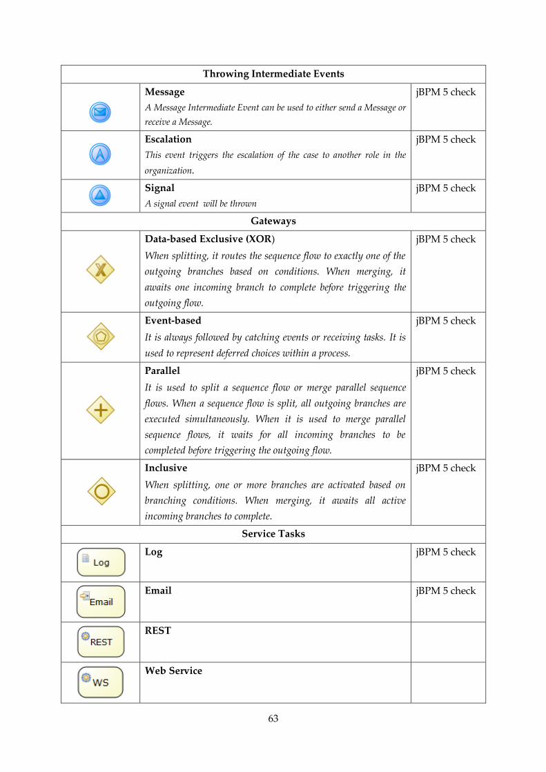
63
Throwing Intermediate Events
Message
A Message Intermediate Event can be used to either send a Message or
receive a Message.
jBPM 5 check
Escalation
This event triggers the escalation of the case to another role in the
organization.
jBPM 5 check
Signal
A signal event will be thrown
jBPM 5 check
Gateways
Data-based Exclusive (XOR)
When splitting, it routes the sequence flow to exactly one of the
outgoing branches based on conditions. When merging, it
awaits one incoming branch to complete before triggering the
outgoing flow.
jBPM 5 check
Event-based
It is always followed by catching events or receiving tasks. It is
used to represent deferred choices within a process.
jBPM 5 check
Parallel
It is used to split a sequence flow or merge parallel sequence
flows. When a sequence flow is split, all outgoing branches are
executed simultaneously. When it is used to merge parallel
sequence flows, it waits for all incoming branches to be
completed before triggering the outgoing flow.
jBPM 5 check
Inclusive
When splitting, one or more branches are activated based on
branching conditions. When merging, it awaits all active
incoming branches to complete.
jBPM 5 check
Service Tasks
Log jBPM 5 check
Email jBPM 5 check
REST
Web Service
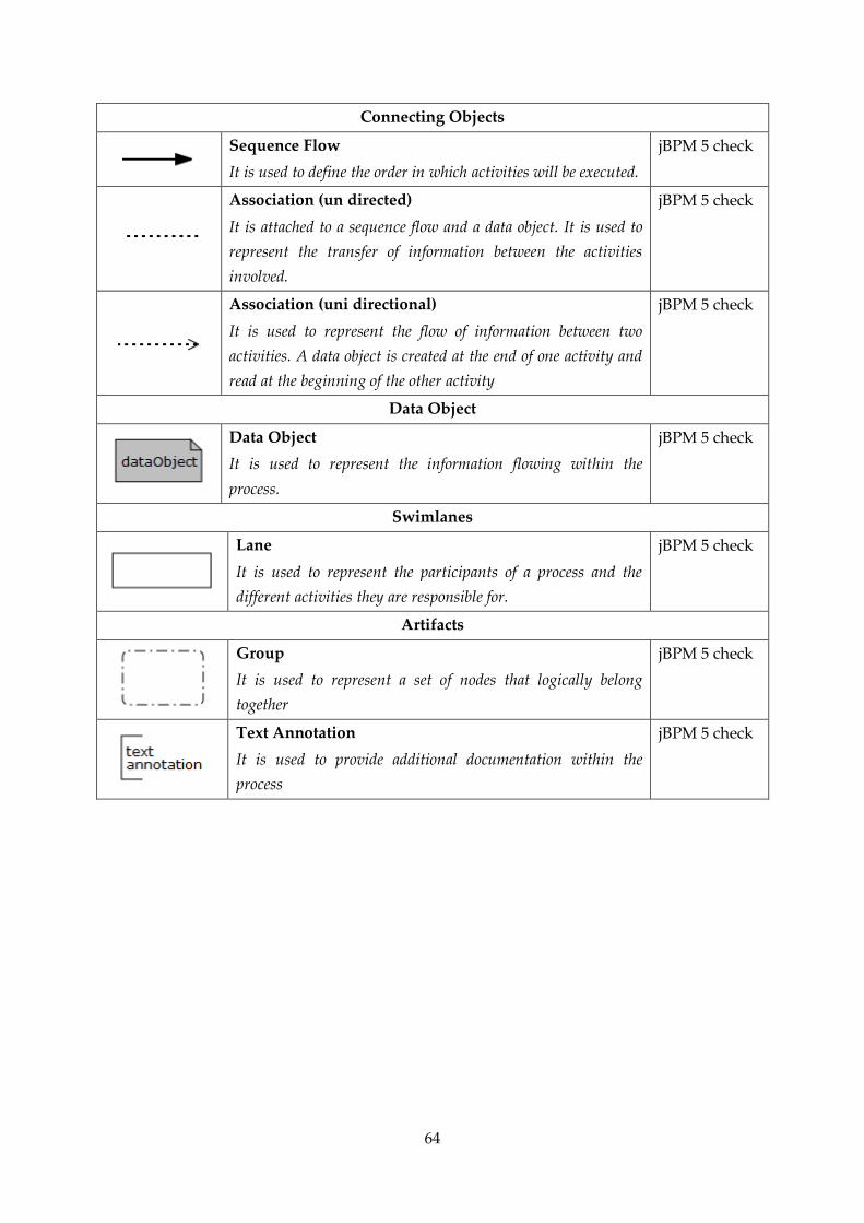
64
Connecting Objects
Sequence Flow
It is used to define the order in which activities will be executed.
jBPM 5 check
Association (un directed)
It is attached to a sequence flow and a data object. It is used to
represent the transfer of information between the activities
involved.
jBPM 5 check
Association (uni directional)
It is used to represent the flow of information between two
activities. A data object is created at the end of one activity and
read at the beginning of the other activity
jBPM 5 check
Data Object
Data Object
It is used to represent the information flowing within the
process.
jBPM 5 check
Swimlanes
Lane
It is used to represent the participants of a process and the
different activities they are responsible for.
jBPM 5 check
Artifacts
Group
It is used to represent a set of nodes that logically belong
together
jBPM 5 check
Text Annotation
It is used to provide additional documentation within the
process
jBPM 5 check

65
B.2. Workflow patterns in jBPM 6
A list of the different workflow patterns supported by jBPM 6 can be seen in Table 4
Table 4: Workflow patterns supported in jBPM 6
Workflow Patterns
Simple Merge
Implicit Termination
Deferred Choice
Synchronization
Multiple Instances without
synchronization

66
Synchronizing Merge
Exclusive Choice
Parallel Split
XOR Split
Sequence
Arbitrary cycles

67
Appendix C. Business Process Simulation
C.1. Business Process Simulation in jBPM 6
Since the release of jBPM 5.4, simulation capabilities have been introduced in the web-based
designer. This process simulation tool is compatible with the Business Process Simulation
Interchange Standard (BPSim) which is a WfMC standard [52]. The simulation relies on the
different possible execution paths rather than process data.
In order to run simulations in jBPM, the business process must be correctly modeled using
the BPMN 2.0 semantics. Further each BPMN 2.0 notation in the process model has specific
simulation properties which must be specified. A list of the different simulation properties
for each BPMN 2.0 constructs can be seen in Table 5. It is possible to visually validate the
process model to check if the BPMN 2.0 semantics has been correctly used. In case, certain
nodes contain validation errors, then those nodes are highlighted and by clicking on the
node, a description of the error can be seen.
Before running the simulation, certain simulation session details must also be specified,
namely the number of process instances to be created and triggered, and the specific interval
time (inter-arrival time) between each process instance. The results of the simulation can be
seen in a simulation tab within the web-based designer. The results can be viewed from 3
different perspectives – the process perspective, activity perspective and path perspective.
In the process perspective, various simulation graphs ( bar charts and pie charts) can be seen
showing the execution time (minimum, maximum, average)of the process , the number of
activity instances and the total cost (minimum , maximum ,average) involved for executing
the process. Moreover the data in these charts can also be filtered. There is also a Timeline
feature which allows us to move forward in time, and see the execution times of various
activities for all process instances.
In the activity perspective, the minimum, maximum and average execution time, wait time ,
resource utilization and resource cost can be seen for each activity.
Finally in the path perspective, all possible paths are highlighted and the number of
instances traversing a particular path can be seen as a pie chart. A path is a set of activities
followed sequentially from the start event to the end event, and it may include loops.
A sample model can be seen in Figure 26, along with its simulation results at the process
perspective in Figure 27. The timeline feature at the process perspective can also be seen in
Figure 28. Simulation results for the activity perspective and path perspective can be seen in
Figure 29 and Figure 30 respectively.

68
Table 5: Simulation properties for the various BPMN 2 constructs supported by jBPM
BPMN2 construct Simulation Properties
Tasks User Cost per time unit
Distribution Type
Processing Time
Staff availability
Working hours
Send/Receive
Service
Business Rule
Manual
Script
Cost per time unit
Distribution Type
Processing Time
Sub Processes Reusable
Multiple Instances
Embedded
Ad-Hoc
Event
Cost per time unit
Distribution Type
Processing Time
Start Events
Message
Timer
Escalation
Conditional
Error
Compensation
Signal
Distribution Type
Processing Time
End Events Message
Escalation
Error
Cancel
Compensation
Signal
Terminate
Distribution Type
Processing Time
Catching Intermediate
Events
Timer Distribution Type
Processing Time
Wait Time
Message
Escalation
Conditional
Error
Compensation
Signal
Distribution Type
Processing Time
Throwing Intermediate
Events
Message
Escalation
Signal
Distribution Type
Processing Time
Connecting Objects Sequence Flow Probability

69
Figure 26: Sample model
Figure 27: Simulation results at the process perspective

70
Figure 28: Simulation results at the process perspective -Timeline feature
Figure 29: Simulation results at the activity perspective
Figure 30: Simulation results at the path perspective

71
C.2. Problems and limitations in jBPM Business Process Simulations
1. The simulation engine does not run for some models or when the simulation scenario
properties have a large number of process instances to be created and triggered.
Figure 31 and Figure 32 shows two models, where the simulation engine did not run.
Figure 31: Simulation engine does not run for the model (1)
Figure 32: Simulation engine does not run for the model (2)
2. When there are 15-20 paths in a process model, all paths cannot be visually shown.
3. Simulation supports only a limited number of distribution types- namely Poisson,
uniform and normal distributions as shown in Table 6.

72
Table 6: Distribution types and their processing time
Distribution Types Processing Time
Poisson distribution Mean processing time
Normal distribution Mean processing time and standard deviation
Uniform distribution Maximum, minimum processing times
4. The inter–arrival rate of process instances has to be a constant value. In reality it
usually follows a particular distribution type.
5. For sub processes (embedded, reusable tasks), it is not possible to drill down and
analyze simulation results of the activities within.
6. Incorrect behavior of BPMN semantic sometimes. For instance, Figure 33, shows a
model where a process path includes both Task 3 and Task 4 from an XOR gateway.
Figure 33: Incorrect behavior for XOR gateway
7. Currently resource utilization is calculated for each human task based on the number
of staff available for the given task and the wait time. The simulation does not
support the concept of pooled resources when calculating resource utilization.
For instance, consider a sample model as shown in Figure 34. In the process there are
3 tasks done in parallel. Task 1 and Task 3 can be done by doctors and Task 2 can be
done by nurses. Let’s assume there are 5 doctors available to do Task 1 and Task 3,
and 5 nurses available to do Task 2. The number of doctors and nurses will be
specified in the Staff Available simulation property of the respective human task
nodes.

73
For each human task node, the execution time is set to follow a Normal distribution,
with a mean processing time of 10 minutes, and a standard deviation of 1.
Additionally the simulation scenario properties include 100 process instances to be
created and triggered, with an inter-arrival time of 20 minutes.
Figure 34: Sample model 1 for checking resource utilization
Table 7 shows the resource utilization for each task, after running the simulation. Here we
can observe that the resource utilization for task 1 and task 3 are nearly the same.
Table 7: Resource utilization at the activity perspective for Sample model 1(in Figure 34)
Resource Utilization Maximum (%) Minimum (%) Average (%)
Task 1 47 0 11.64
Task 2 36 0 9.02
Task 3 46 0 11.45
If the model is further extended by adding two more human task nodes- task 4 and task 5 as
shown in Figure 35 and then setting the simulation properties of the two nodes to have 5
staff available.
Figure 35: Sample model 2 for checking resource utilization

74
Then the resource utilization found after running simulations can be seen in Table 8. Once
again, we can observe that the resource utilization is nearly the same for tasks 1, 2, 4 and 5.
Table 8: Resource utilization at the activity perspective for Sample model 2(in Figure 35)
Resource Utilization Maximum (%) Minimum (%) Average (%)
Task 1 52 0 12.94
Task 2 37 0 9.21
Task 3 38 0 9.49
Task 4 40 0 10.01
Task 5 42 0 10.36
When running simulations, the resource utilization should be calculated based on the roles.
For instance, if there are 5 employees who have the role of a doctor, the resource utilization
should give a single value for the role doctor. Currently this concept of pooled resources is
not supported in jBPM simulations.

75
Appendix D. Business Activity Monitoring
jBPM 6 also provides a Business Activity Monitoring module (also called a Dashboard
Builder) which is used to create dashboards. These dashboards are used to display key
performance indicators relevant to a business process. Two types of Dashboards can be built
using this module – Business Dashboards which can use data retrieved from any relational
database through SQL queries; and a Process Dashboard which uses data retrieved from the
jBPM database (the database where the jBPM engine will persist data) [25]. In Figure 36, we
can some process dashboards.
Figure 36: Process dashboards

76
Appendix E. Installation and setup of jBPM 6.0.1
jBPM 6.0.1 is installed and a demo setup will be created, which will include the core engine
(rule engine and workflow engine) and a web console deployed on JBoss Application Server
7. The Drools and jBPM plugins for the Eclipse IDE will also be installed along with an
Eclipse based BPMN2 modeler. Additionally, jBPM 6.0.1 has been configured to use the
PostgreSQL database for persisting runtime data.
E.1. Steps to install jBPM 6.0.1
1) Download and install Java JDK 1.5+ and Ant 1.7+
They can be downloaded from -
Java: http://java.sun.com/javase/downloads/index.jsp
Ant: http://ant.apache.org/bindownload.cgi
2) Open the Advanced System Settings, and click on the Environment Variables tab, then
a. Set ANT_HOME, JAVA_HOME to the path where ANT and Java was
installed respectively, as shown in Figure 37.
Figure 37: Setting system properties (1)
b. Add the location of the bin folder of ANT and Java, to the Path in System
Variables, as shown in Figure 38.

77
Figure 38: Setting system properties (2)
3) Download jbpm-6.0.1.Final-installer-full.zip from -
http://sourceforge.net/projects/jbpm/files/
4) Unzip jbpm-6.0.1.Final-installer-full.zip to a folder at a particular path
5) Now open the Command Prompt, and point the cursor to the path where jbpm-
6.0.1.Final-installer-full.zip was unzipped.
6) Then type command - ant install.demo
This will do the following: -
Download JBoss Application Server 7
Download Eclipse
Install the jBPM Console into JBoss AS
Install the jBPM Eclipse plugin
Install the Drools Eclipse plugin
Alternatively if you do not wish to install Eclipse, then type command –
ant install.demo.noeclipse
7) Then to start the setup, type the following command in the Command Prompt -
ant.start.demo
This will do the following -
Starts the H2 database
Starts the JBoss Application Server
Start Eclipse
Start the jBPM Human Task Service
Alternatively, if you wish not to start Eclipse, then type the command -
ant.start.demo.noeclipse

78
8) The KIE Workbench can then be opened at http://localhost:8080/jbpm-console
It is recommended to use Mozilla Firefox web browser.
9) Once the work has been completed, type the following command in the command
prompt- ant stop.demo

79
E.2. Steps to create users in jBPM
1) In the folder where jbpm-6.0.1.Final-installer-full is installed, then go to folder jboss-as-
7.1.1.Final\bin , and open the file - add-user.bat
Opening the Batch file, will show a Command Prompt window as shown in Figure 39.
Figure 39: Creating users in jBPM (1)
Then in order to create users, do the following:-
Choose option b for creating an application user
Leave Realm empty
Enter a username and password ,which must be different
(For instance – Username is secretary and Password is abcd )
Enter the role which this user belongs to (For instance- role is user).
The different roles provided by jBPM can be seen in Table 9
Table 9: Predefined roles in jBPM 6 [25]
Role Description
admin Administrates the BPMS system. Have full access rights to make any changes
necessary. Also has the ability to add and remove users from the system.
analyst Creates rules, models, process flows, forms, dashboards and handles process
change requests.
developer Implements code required for process to work. Mostly uses the JBoss
Developer Studio connection to view processes, but may use the web tool
occasionally.
manager Viewer of the system that is interested in statistics around the business
processes and their performance, business indicators, and other reporting of
the system and people who interact with the system.
user Daily user of the system to take actions on business tasks that are required for
the processes to continue forward. Works primarily with the task lists

80
2) Then go to jboss-as-7.1.1.Final\standalone\configuration folder, and open the
roles.properties file
Append to the list the username and its respective role (secretary=user) as shown in
Figure 40.
Figure 40: Creating users in jBPM (2)
3) In the same folder, open the users. properties file, and enter the username and password
(secretary= abcd) as shown in Figure 41.
Figure 41: Creating users in jBPM (3)

81
E.3. Problems in jBPM
1) After starting the demo setup using ant.start.demo, and then going to
http://localhost:8080/jbpm-console, the error shown in Figure 42 comes on screen ,
although JBoss Application Server is still running
Figure 42: Startup error
This is a startup time lag. Wait for 1-2 minutes and refresh screen.
2) After modeling a process and executing the process definition and then if you delete
the process model before performing the tasks in the process, then the active process
instance cannot be deleted.
3) When modeling a process in the jBPM web based designer,
The model often gets disturbed at gateways, especially when trying to edit
gateway properties.
Sometimes it becomes impossible to connect an object to another object
(connection arrow to object does not work).
Sometimes you cannot place objects on the editor/workspace.
5) Sometimes the project explorer may disappear (for instance, after deleting a
repository) as shown in Figure 43. Then it is not possible to author a process.
(http://drools.46999.n3.nabble.com/Project-Explorer-has-dissappeared-in-KIE-
Workbench-td4027767.html)
Figure 43: Project explorer has disappeared in the KIE workbench
4) Sometimes when reopening a previously saved model in the jBPM web based
designer, the error shown in Figure 44 occurs. If this error occurs to any one process
in the project then you cannot, build and deploy the process definition. Moreover
you cannot see the option to delete the process as well.
(https://issues.jboss.org/browse/JBPM-4203)

82
Figure 44: Error in loading the process
Workaround:
a. After validating model, download the source code to your local file system. And
only then save it in the web editor.
b. Restart the JBoss application server.
6) It is easier to build larger processes using the Eclipse BPMN2.0 modeler. However
sometimes it is not possible to upload those models into the web based designer as
shown in Figure 45 .

83
Figure 45: Cannot import BPMN models into the jBPM web based designer

84
Appendix F. Optimization algorithms in OptaPlanner
In Table 10, the various optimization algorithms supported by OptaPlanner is shown.
Table 10: Optimization algorithms supported by OptaPlanner [17]
Algorithm Scalable Optimal Ease of
use Tweakable
Requires
CH
Exact algorithms
Brute force 0/5 5/5 5/5 0/5 No
Depth- first search 0/5 5/5 4/5 1/5 No
Construction heuristics (CH)
First Fit 5/5 1/5 5/5 1/5 No
First Fit Decreasing 5/5 2/5 4/5 2/5 No
Best Fit 5/5 2/5 4/5 2/5 No
Best Fit Decreasing 5/5 2/5 4/5 2/5 No
Cheapest Insertion 3/5 2/5 5/5 2/5 No
Regret Insertion 3/5 2/5 5/5 2/5 No
Metaheuristics
Local Search
Hill-Climbing 5/5 2/5 4/5 3/5 Yes
Tabu Search 5/5 4/5 3/5 5/5 Yes
Simulated Annealing 5/5 4/5 2/5 5/5 Yes
Late Acceptance 5/5 4/5 3/5 5/5 Yes
Step Counting Hill
Climbing 5/5 4/5 3/5 5/5 Yes
Evolutionary Algorithms
Evolutionary Strategies 4/5 3/5 2/5 5/5 Yes
Genetic Algorithms 4/5 3/5 2/5 5/5 Yes

85
Appendix G. Rules for Pathologist Case Assignment problem
Figure 46: Negative constraints (Hard and Soft score)
Figure 47: Scenario where there are 4 cases and 2 pathologists - for Rule 1

86
Figure 48: Representing scoring logic for rule 1
Figure 49: Scenario where there are 4 cases and 2 pathologists – for Rule 2

87
Figure 50: Representing scoring logic for rule 2

88
Figure 51: Scenario where there are 10 cases and 3 pathologists- for Rule 3
Figure 52: Standard deviation of complexity of cases assigned to pathologists is zero

89

90

91
Appendix H. Creating the OptaPlanner Work Item
The following steps have to be followed in order to create the OptaPlanner WorkItem.
Step 1) Create a work item definition using the MVEL language
1.1 Create a project in the KIE workbench from the project authoring perspective
1.2 Then open the default file called WorkDefinitions. wid, which contains some
default WorkItems (Email, Log, Web Service, Rest).
It is in this file, we will add the new work item definition as shown in the Figure 53.
Since the work item is being defined in an existing file (WorkDefinitions. wid) from
the KIE workbench, it is already registered with the process engine.
Then the new work item will appear in the palette of the process modeler for a new
process
Figure 53: Creating the WorkItem definition for the OptaPlanner WorkItem
Step 2) Create a java work item handler in Eclipse
2.1 Create a maven project and add the kie-api artifact with the 6.0.0.redhat version
value as the project dependency.
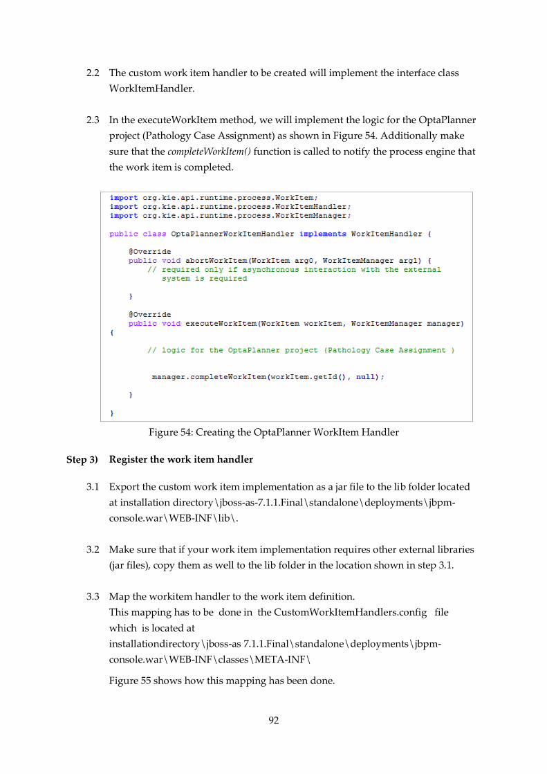
92
2.2 The custom work item handler to be created will implement the interface class
WorkItemHandler.
2.3 In the executeWorkItem method, we will implement the logic for the OptaPlanner
project (Pathology Case Assignment) as shown in Figure 54. Additionally make
sure that the completeWorkItem() function is called to notify the process engine that
the work item is completed.
Figure 54: Creating the OptaPlanner WorkItem Handler
Step 3) Register the work item handler
3.1 Export the custom work item implementation as a jar file to the lib folder located
at installation directory\jboss-as-7.1.1.Final\standalone\deployments\jbpm-
console.war\WEB-INF\lib\.
3.2 Make sure that if your work item implementation requires other external libraries
(jar files), copy them as well to the lib folder in the location shown in step 3.1.
3.3 Map the workitem handler to the work item definition.
This mapping has to be done in the CustomWorkItemHandlers.config file
which is located at
installationdirectory\jboss-as 7.1.1.Final\standalone\deployments\jbpm-
console.war\WEB-INF\classes\META-INF\
Figure 55 shows how this mapping has been done.

93
Figure 55: Mapping OptaPlanner WorkItem Handler to respective WorkItem definition
3.4 Copy default.session.template file from
installationdirectory \jboss-as-7.1.1.Final\standalone\deployments\jbpm-
console.war\WEB-INF\classes\to the configuration folder located at
installationdirectory \jboss-as-7.1.1.Final\standalone\
And rename the file as session.template with and it should include some
modifications as shown in Figure 56.
Figure 56: Modifying the session template
Step 4) Restart the server
Now the custom work item can be executed from the KIE workbench