integrating optical networking into the packet …...integrating optical networking into the packet...
TRANSCRIPT

INTEGRATING OPTICAL NETWORKING INTO THE PACKET CORE Tim Nagy - [email protected] 7 September 2012

2 Copyright © 2012 Juniper Networks, Inc. www.juniper.net
OPTICAL INTEGRATION IN CORE ROUTING
For years, the optical portion of the network has been separate to – and managed separately from – the IP core
New standards and advancing technology is changing that status quo now Miniaturization of components G.698.2 standard – “black link” Management hooks into optical/router elements Integration between transmission failure and IP/MPLS reroute
We will examine how this landscape is changing – but first, a quick overview of optical networking terms and functionality

OPTICAL DEVICES/TERMINOLOGY

4 Copyright © 2012 Juniper Networks, Inc. www.juniper.net
SIMPLE DWDM TRANSMISSION SYSTEM
Ten individual gray signals converted to colored signals via wavelength-specific transmitters.
Ten wavelengths combined onto single fiber using DWDM multiplexer
Ten wavelengths separated at end of single fiber transmission link using DWDM demultiplexer.
Commercial DWDM transmission systems today transmit more than 80 wavelengths per fiber.
TX RX DWDM Multiplexer
DWDM Demultiplexer
10 different wavelengths on a single optical fiber

5 Copyright © 2012 Juniper Networks, Inc. www.juniper.net
OPTICAL ADD-DROP MULTIPLEXER (OADM)
OADM keeps pass-through wavelengths in optical domain
Only wavelengths being added or dropped get converted to electrical domain
OADMs for building optical ring networks Higher degree OADMs useful for building optical mesh networks
Reconfigurable OADMs (ROADMs) allow rapid, remote reconfiguration of add-drop wavelengths
Latest generation are multi-degree ROADMs
OADM (schematic representation only)
(only one direction shown for simplicity) Drop
wavelengths Add wavelengths
6 Copyright © 2012 Juniper Networks, Inc. www.juniper.net
Router
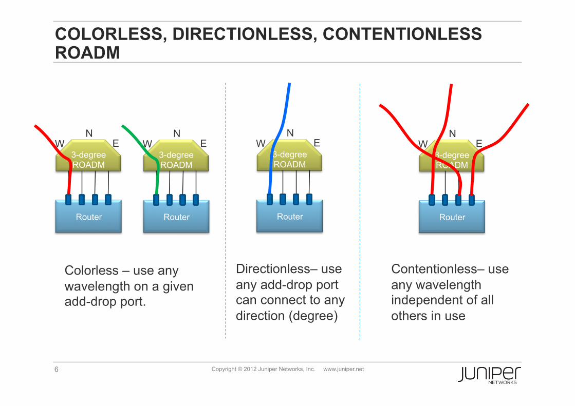
COLORLESS, DIRECTIONLESS, CONTENTIONLESS ROADM
3-degree ROADM
N E W
Router
3-degree ROADM
N E W
Colorless – use any wavelength on a given add-drop port.
Router
3-degree ROADM
N E W
Directionless– use any add-drop port can connect to any direction (degree)
Router
3-degree ROADM
N E W
Contentionless– use any wavelength independent of all others in use
7 Copyright © 2012 Juniper Networks, Inc. www.juniper.net
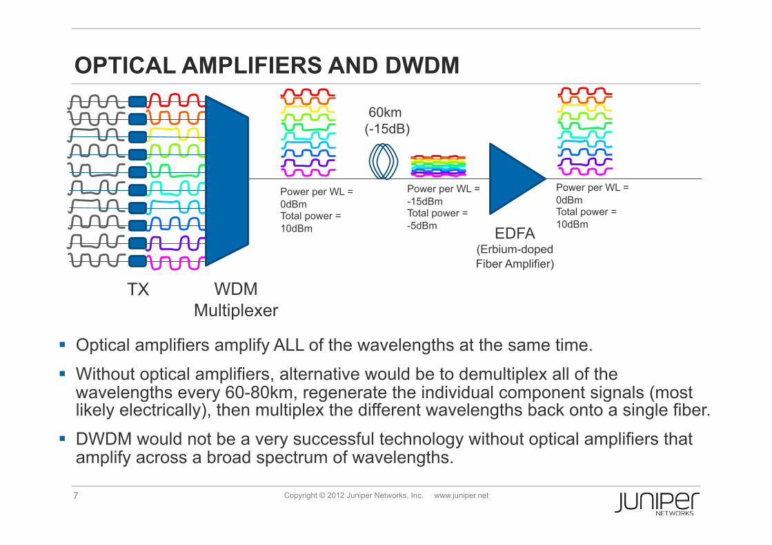
OPTICAL AMPLIFIERS AND DWDM
Optical amplifiers amplify ALL of the wavelengths at the same time.
Without optical amplifiers, alternative would be to demultiplex all of the wavelengths every 60-80km, regenerate the individual component signals (most likely electrically), then multiplex the different wavelengths back onto a single fiber.
DWDM would not be a very successful technology without optical amplifiers that amplify across a broad spectrum of wavelengths.
TX WDM Multiplexer
EDFA (Erbium-doped Fiber Amplifier)
Power per WL = 0dBm Total power = 10dBm
Power per WL = -15dBm Total power = -5dBm
60km (-15dB)
Power per WL = 0dBm Total power = 10dBm
8 Copyright © 2012 Juniper Networks, Inc. www.juniper.net
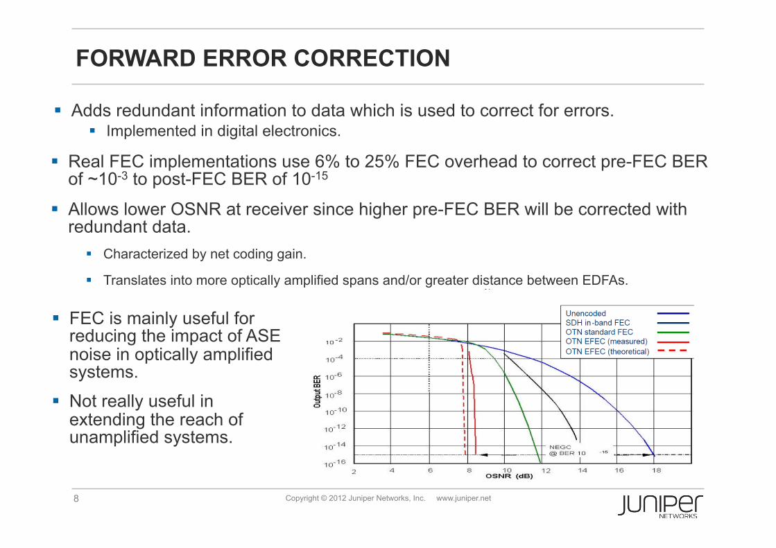
FORWARD ERROR CORRECTION
Adds redundant information to data which is used to correct for errors. Implemented in digital electronics.
Real FEC implementations use 6% to 25% FEC overhead to correct pre-FEC BER of ~10-3 to post-FEC BER of 10-15
Allows lower OSNR at receiver since higher pre-FEC BER will be corrected with redundant data.
Characterized by net coding gain.
Translates into more optically amplified spans and/or greater distance between EDFAs.
FEC is mainly useful for reducing the impact of ASE noise in optically amplified systems.
Not really useful in extending the reach of unamplified systems.

9 Copyright © 2012 Juniper Networks, Inc. www.juniper.net
THE DIFFERENT MEANINGS OF OTN
OTN (Optical Transport Network) standardized in ITU G.709.
OTN as generic term for optical networking and DWDM Not very helpful use of term in this context
OTN encapsulation Provides FEC and OAM Referred to as OTN termination when used on
router or MPLS switch interfaces for packet traffic.
OTN encapsulation
Approximate bitrate*
ODU0 1.25 Gbps
OTU1/ODU1 2.5 Gbps
OTU2/ODU2 10 Gbps
OTU3/ODU3 40Gbps
OTU4/ODU4 100Gbps
OTN Switching Next generation of TDM / circuit switching technology Covering higher speeds than SONET/SDH Defines mapping of lower speed circuits into higher speed circuits.
* See G.709 for exact values. OTUk rate > ODUk rate > OPUk rate due to FEC and other overhead.
10 Copyright © 2012 Juniper Networks, Inc. www.juniper.net
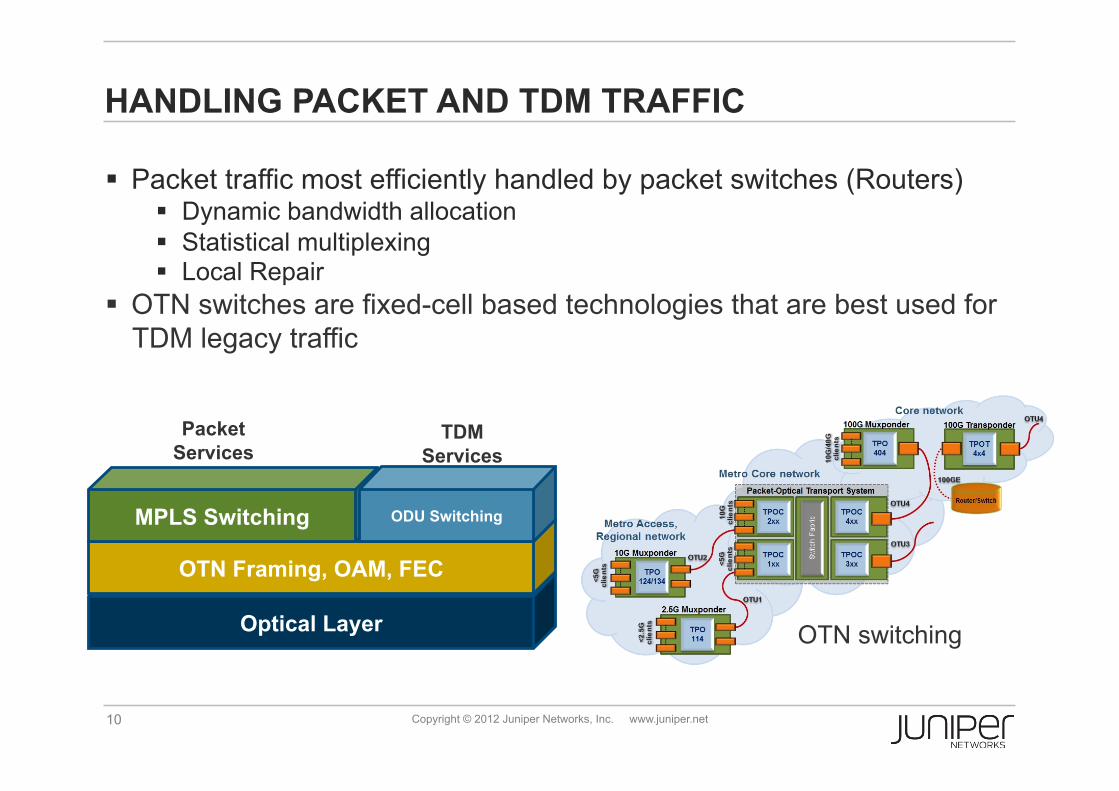
Packet traffic most efficiently handled by packet switches (Routers) Dynamic bandwidth allocation Statistical multiplexing Local Repair
OTN switches are fixed-cell based technologies that are best used for TDM legacy traffic
HANDLING PACKET AND TDM TRAFFIC
Optical Layer
OTN Framing, OAM, FEC
MPLS Switching ODU Switching
Packet Services
TDM Services
OTN switching
INTEGRATING OPTICAL NETWORKING INTO THE IP/MPLS CORE
12 Copyright © 2012 Juniper Networks, Inc. www.juniper.net
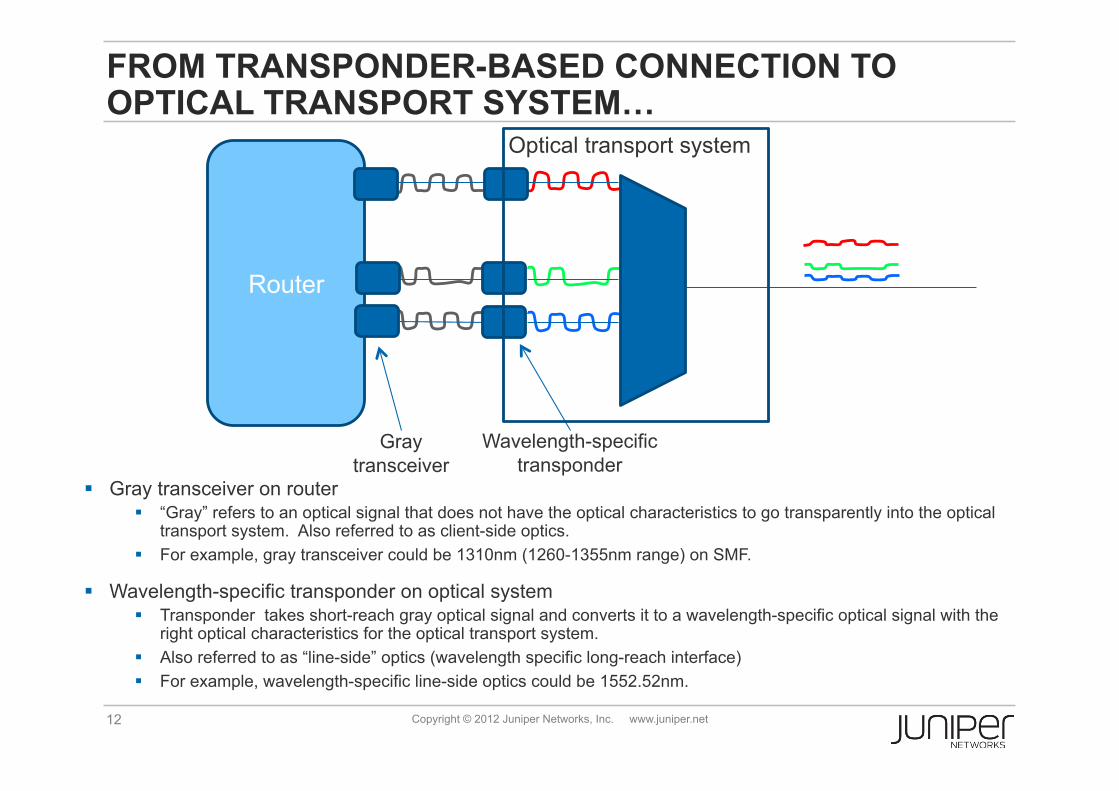
FROM TRANSPONDER-BASED CONNECTION TO OPTICAL TRANSPORT SYSTEM…
Router
Gray transceiver on router “Gray” refers to an optical signal that does not have the optical characteristics to go transparently into the optical
transport system. Also referred to as client-side optics. For example, gray transceiver could be 1310nm (1260-1355nm range) on SMF.
Wavelength-specific transponder on optical system Transponder takes short-reach gray optical signal and converts it to a wavelength-specific optical signal with the
right optical characteristics for the optical transport system. Also referred to as “line-side” optics (wavelength specific long-reach interface) For example, wavelength-specific line-side optics could be 1552.52nm.
Wavelength-specific transponder
Optical transport system
Gray transceiver

13 Copyright © 2012 Juniper Networks, Inc. www.juniper.net
… TO TRANSPONDER-LESS CONNECTION TO OPTICAL TRANSPORT SYSTEM
Router
Wavelength-specific transceiver on router Optical signal with wavelength (for example,1552.52nm) and longer reach optical characteristics Allows it to go directly onto optical system without a transponder (no O/E/O conversion) Sometimes referred to as “alien wavelengths” from point of view of optical transport system.
Less expensive due to fewer O/E/O conversions.
Wavelength-specific transceivers
Optical transport system

14 Copyright © 2012 Juniper Networks, Inc. www.juniper.net
Grey interfaces versus Colored interfaces
No transponder on DWDM system Colored, tunable 100G interface on the router
Transponder on DWDM
system
Transponder on DWDM
system
CFP grey optics CFP grey optics
Optical transport system
Router Router
Router Router
Long-haul coloured optics
Optical transport system

15 Copyright © 2012 Juniper Networks, Inc. www.juniper.net
FROM 100GBASE-LR4… Standardized in 802.3ba-2010 for 10km reach on SMF.
Uses four parallel wavelengths running at 25.8 Gbps each 4x25Gbps transmitters easier than 1x100Gbps Lower bit rate also reduces effect of chromatic dispersion
Lasers in 1300nm range with 800 GHz channel separation (LAN-WDM) 1300nm range chosen for low dispersion for single-mode fiber
“Grey” client interface

16 Copyright © 2012 Juniper Networks, Inc. www.juniper.net
… TO 100G COHERENT PM-QPSK DWDM Rx
RZ Qx Iy
CW
Ix
PBC
Tx
S L
ADC
90º hyb
90º hyb
Ix
Qx
Iy
Qy
DSP PBS
Link PolSate
Chromatic Dispersion
PMD
τ τ y
x
ROADM
The Optical Channel
Qy NL effects
• Polarization multiplexing (PM): • Use both polarizations of light to carry independent signals • Lowers symbol rate by a factor of 2 • Allows for electronic compensation of PMD
• Quadrature-phase shift keying (QPSK): • Uses a constellation with 4 symbols • Lowers symbol rate by another factor of 2 • Captures phase information allowing digital signal processing (DSP) to compensate for chromatic dispersion electronically.
• Coherent detection: • Laser at receiver tuned to wavelength of received light selects detected wavelength in DWDM system
• DWDM: • Optical signal still fits in 50GHz channel spacing for DWDM
• Benefit: • 2500 km transmission at 100Gbps with no external dispersion compensation and high PMD tolerance.

17 Copyright © 2012 Juniper Networks, Inc. www.juniper.net
Set of protocols to dynamically provision optical layer resources Within optical layer From routers to optical layer
Generalized MPLS (GMPLS) reuses and extends protocols used by MPLS (ISIS or OSPF and RSVP) and adds LMP (link management protocol)
GMPLS has been around since 2004 but not widely deployed on routers to signal wavelength setup
Optical layer is becoming more flexible More able to respond to arbitrary wavelength set up demands from packet
layer Flexible ROADM technology (directionless, colorless, contentionless) 100G coherent detection with digital signal processing automates dispersion
compensation.
Packet layer requirements increasing
CONTROL PLANE: GMPLS (GENERALIZED MPLS)

18 Copyright © 2012 Juniper Networks, Inc. www.juniper.net
CURRENT STANDARDS WORK
Black Link in ITU-T: Recommendation ITU-T G.698.2: Amplified multichannel dense
wavelength division multiplexing applications with single channel optical interfaces
Black Link Framework: http://tools.ietf.org/html/draft-kunze-g-698-2-management-control-framework-01
Black Link Management: http://tools.ietf.org/html/draft-galimbe-kunze-g-698-2-snmp-mib-01
GMPLS-UNI+: http://tools.ietf.org/html/draft-beeram-ccamp-gmpls-uni-bcp-00
1
3
2

19 Copyright © 2012 Juniper Networks, Inc. www.juniper.net
PACKET/OPTICAL NETWORKING: AN OPEN PACKET OPTICAL TRANSPORT ECO-SYSTEM
GMPLS / WSON
MPLS
UNI
SNMP SNMP
NMS
GMPLS UNI
ITU-T G.698.2
2
1
3
OXC OXC
Router Router
20 Copyright © 2012 Juniper Networks, Inc. www.juniper.net
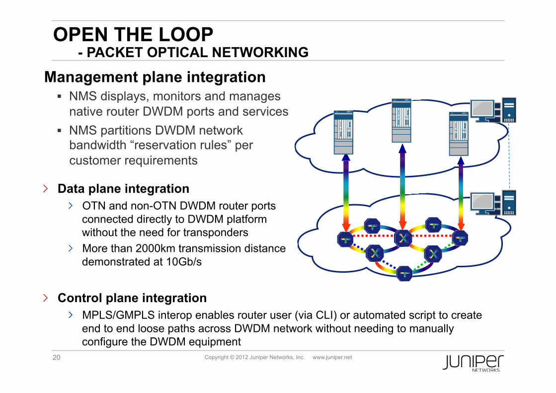
OPEN THE LOOP - PACKET OPTICAL NETWORKING
Management plane integration NMS displays, monitors and manages
native router DWDM ports and services NMS partitions DWDM network
bandwidth “reservation rules” per customer requirements
" Control plane integration " MPLS/GMPLS interop enables router user (via CLI) or automated script to create
end to end loose paths across DWDM network without needing to manually configure the DWDM equipment
" Data plane integration " OTN and non-OTN DWDM router ports
connected directly to DWDM platform without the need for transponders
" More than 2000km transmission distance demonstrated at 10Gb/s

21 Copyright © 2012 Juniper Networks, Inc. www.juniper.net
RESPONDING TO UNPREDICTABLE GROWTH WITH AUTO-WAVELENGTH (ANIMATED)
A
B
C
D
• Auto-wavelength responds quickly to the actual demand growth. • If only A to C demand grows, only A to C wavelength is added. • Avoids over-provisioning and saves capex.
MP
LS
switc
h
RO
AD
M
MPLS switch
ROADM
MP
LS
switch
RO
AD
M
MPLS switch
ROADM

22 Copyright © 2012 Juniper Networks, Inc. www.juniper.net
PROACTIVE PROTECTION
FEC / OTN
Framing
Receive End EDFA
TXP Op2cs
FEC / OTN
Framing FRR Event
OTU Frame W/ APS
OTU Frame W/ APS
Transmit End
ROADM EDFA
TXP Op2cs X
Reroute Request
Router Router
TIME
Pre-
FEC
BER
Clear Threshold
Degrade Threshold
Fail Threshold
Degrade Window
Fail Window
Interrupt: Degrade
Interrupt: Fail
Interrupt: Clear Clear
Window
Trigger FRR to avoid any packet drop
Programmable Fail
Programmable Degrade
Programmable Clear Threshold
• FRR: Hitless switch over based pre-FEC BER
• Packet layer protection based on visibility of transport layer performance degradation