integrating layout planning and simulation for logistic nodes
TRANSCRIPT


Integrating Layout Planning andSimulation for Logistic Nodes
Anne Schwientek1, Ann-Kathrin Lange1, Markus Holzner2, Margit Thomsen2,Carlos Jahn1
1 – TUHH - Institute of Maritime Logistics
2 – INCONTROL Simulation Soft are
When a new logistic node (e.g. a terminal) is planned or needs to be optimized,layout planning and simulation analysis are typically two separate tasks. Whilelayout planning is an intuitive and visual but static approach, simulation is dy-namic butmore complex. Integrating both approacheswould be highly beneficial.The idea of the integrated tool is to create first a static layout on a touchscreenplanning table. After inserting relevant parameters and selecting preferred lo-gistic strategies, the layout is converted directly into an executable simulationmodel. Based on the simulation, e.g. different layout or equipment variations canbe tested.
Main challenges for a successful integration are the logistic processes and strate-gieson the terminal. Botharenot included in the layoutplanning, butareessentialfor a valid and realistic simulation model. Therefore, relevant process and strat-egy variations as well as typical research questions are defined. The integratedapproach is an innovative solution to optimize planned as well as existing termi-nals. Typically, conducting layout planning and simulation studies separately is avery time consuming task. Integrating both is more efficient, closer to reality andmore cooperative by allowing to involve more stakeholders at an earlier stage.
Keywords: Simulation; Layout Planning; Inland Waterway Container Terminal;Intermodal Transport
First recieved: 04.Jun.2018 Accepted: 15.Jun.2018
21

Integrating Layout Planning and Simulation for Logistic Nodes
1 Introduction
In order to meet the high demands for faster handling in a shorter time windowand with higher quality, it is necessary that logistical nodes in ports and thehinterland continuously review their operational and administrative processesand adapt them if necessary. This applies in particular to container terminals(Stahlbock and Voß, 2008) and intermodal terminals due to the high transship-ment numbers and the increasing requirements. Therefore, when planning newand existing logistic nodes, it is important to use space and technical systems forhandling, transport and storage as efficientl as possible. Simulation is becomingincreasingly important for securing and optimizing solutions for planning pro-cesses in logistics in general (März andWeigert, 2011) and especially for containerterminals. It is increasingly important to integrate the simulation in early planningphases and with little effort.
2 Problem Description
2.1 State of the art
Typically, terminal planning and terminal optimization by simulation studies areseparate tasks. The terminal layout is planned statically using standard layouts,experiences, spreadsheets or other static tools. Afterwards, simulations studiescan be conducted to evaluate and improve the terminal design. This would leadto adjustments in the terminal planning causing a high expenditure of time andhigh personnel costs. Furthermore, creating simulationmodels demands timeand substantial soft are knowledge.
Common simulation tools for material flow and logistics like AnyLogic, AutoMod,CLASS, Demo3D, Enterprise Dynamics, Plant Simulation, Simul8, or Witness baseon object libraries that provide the foundation to create a simulation model.These objects are defined by a number of parameters. The amount of parametershas to be the higher the more realistic the simulation is supposed to be. Thisimplies that modelling large sites containing various parameter constellations isa highly complex and time-consuming task.
Additionally, control mechanisms and algorithms have to be defined to managethe simulation runs. All common tools provide predefined procedures. Practically,
22

2 Problem Description
these procedures have tobe adjustedby re-programmingobjects or programmingnew scripts. Target group of these tools are typically specifically trained usersthat intend to find answers to specific questions regarding an existing terminallayout.
In other areas of logistics, such as production planning (Toth et al., 2008) orconveyor system planning (Wurdig and Wacker, 2008), approaches have alreadybeen taken to integrate planning and simulation. However, these approachescannot be directly transferred to the planning of logistical nodes due to a highnumber of organizational forms, many decision variables, static and dynamicside conditions and many sources of uncertainty, e.g. weather conditions orequipment failures. This is also the reason whymany simulationmodels focus ondefined area of seaport container terminals, e.g. automated storage blocks (i.a.Xin et al., 2014; Kemme, 2012; Canonaco et al., 2007), container gantry cranes (i.a.He et al., 2015; Guo and Huang, 2012; Dai et al., 2004; Liu et al., 2002) or horizontaltransport (i.a. Garro et al. 2015; Tao and Qiu, 2015; Duinkerken et al., 2007). Othersimulationmodels consider container terminals as a whole, but focus onmediumto large seaport container terminals and do not offer the flexibility required forinland terminals or intermodal terminals.
2.2 Objectives
When layout planning and simulation studies for logistic nodes are conducted sep-arately and decoupled, possible synergy effects (such as reducing the modellingtime for a simulation model) are not realized. To approach these deficiencies,it would be beneficial to develop a soft are solution that allows creating staticterminal layouts and to transfer this layout directly to an executable dynamicsimulationmodel including the relevant terminal processes and strategies. Theseprocesses and strategies are of utmost importance for a successful integration asthey represent the essential link between layout planning and simulation. There-fore, they have to be defined beforehand. By integrating intuitive and cooperativelayout planning together with dynamic process mapping within one soft aresolution, the strengths of both tools are combined while the weaknesses of bothtools are eliminated at the same time.
In order to realize the integration of layout planning and simulation, two existingsoft are tools are chosen. Thereby, the planning soft are visTABLE® by plavisand the simulation soft are Enterprise Dynamics® by INCONTROL represent the
23

Integrating Layout Planning and Simulation for Logistic Nodes
respective soft are. The integration can reduce the required time toplana logisticnode significantly as simulationmodels have to bemodelled otherwise by expertsin extensive work based on the designed layout.
Therefore, this innovation directly supports an efficien and rapid planning phaseof logistic nodes to support an extension of transport infrastructure suitable tothe market needs. The integration of layout planning and simulation studies is -in a first step - developed for inland waterway container terminals and terminalsfor intermodal transport. This means that whenever the term ’terminal’ is used inthe following, these two terminal types are described. All other types of terminalssuch as e.g. seaport container terminals are not considered.
2.3 Methodology
2.3.1 Methodology to integrate both software tools
Baseline for such an integrated soft are tool are the system specifications thatdefine all requirements for the tool. This comprises e.g. typical and relevantobjects, processes and strategies to be implemented, but also relevant problemsto be investigated with the tool and interesting output parameters of the tools forusers later on.
Based on the system specifications, the concept is developed. A method needsto be described to define a systematic procedure how to implement the speci-fications. Basically, detailed use cases have to be described containing objects,processes, strategies, problems to be investigated and output parameters. Thisalso includes e.g. describing core elements of a modular object kit and all se-lectable control strategies. Based on this method, detailed definitions of partialsystems to be implemented later on are derived. Thereby, possible end usersshould be involved in this phase to ensure draftin user interfaces suitable fordifferent types of users. Based on these results, a functional architecture of theplanning environment can be derived.
If the concept is developed, the implementation phase begins. First, foundationshave to be laid to allow for an integrated use of both soft are tools. There is a highnumber of interdependencies between results and restrictions from the layoutplanning and their transformation to an executable simulationmodel. These re-strictions require adapting both soft are tools. The previously defined use caseshave to be implemented together with the corresponding algorithms. Necessary
24

2 Problem Description
Figure 1: Methodology
interfaces and data structures that are defined in the system specifications needto be integrated in both soft are tools.
To verify the implemented soft are solution, extensive tests are conducted. Firstof all, the functional capability of the developed soft are tools is verified. Thistest bases on a test plan that contains all relevant test cases (e.g. choice of logisticstrategies) based on systematic parameter variations. Afterwards, the functional-ity of the soft are is validated. Thereby, single specific test cases are considered.Afterwards, two exemplarily test applications show the comparability with realterminals.
Figure 1 displays the methodology. Thereby, the dotted arrows indicate that itmight be reasonable to go back to the previous phase for some adjustments. Theintegrated soft are solution will be developed as a prototype within the Germanresearch project ”ISI-Plan - Integration von ereignis-diskreter Logistiksimulationund Layoutplanung für logistische Knoten” whichmeans ”Integration of event-discrete logistics simulation and layout planning for logistics nodes”. The projectis funded by the German Federal Ministry of Education and Research (BMBF).
25

Integrating Layout Planning and Simulation for Logistic Nodes
2.3.2 Methodology for the system specification
Based on this general methodology, the focus of this paper is on the first part, thesystem specification. Thereby, on the one hand scientific literature on terminallayout planning (e.g. Böse, 2011; Brinkmann, 2005) and terminal simulation (e.g.Dragovic et al., 2017; Angeloudis and Bell, 2011) is considered. On the other hand,the practical operational terminal processes are investigated in detail in order tovalidate the state of the art as well as to ensure the reference to recent terminalchallenges.
First, a desk research is conducted to identify relevant publications in the field ofcontainer terminals. Thereby, not only inlandwaterway terminals and intermodaltransport terminals are considered, but also seaport container terminals. Thisallows to include advanced technologies as well as storage and logistic strategies.Furthermore, websites of relevant logistic nodes as well as available studiesand reports are analyzed to complete the findings with the state of technology.As there are sometimes significant differences between the functionalities andcomplexity of different logistic nodes, the findings are examined regarding theiradaptability to inland waterway and intermodal transport terminals. This way,objects and strategies are considered as well that are less relevant at themomentbut might becomemore important in the future.
Based on the desk research results, interview guidelines are developed that serveas a foundation for visits at two representative terminals. During these visits, de-tailed analyses of terminal operations, relevant parameters, planning issues andpossible future topics are surveyed. Some interesting findings of both approaches(desk research and terminal visits) are presented in the following section.
3 Approach and functionalities
The goal of the research project ISI-Plan is the creation of a functional prototypeconsisting of the innovative integration of the planning table and the logisticalprocess simulation. Therefore, that prototype will support the rapid and efficienplanning and development of logistics hubs.
The tool will be tested in the project by the Institute of Maritime Logistics of theHamburg University of Technology, the Fraunhofer Center for Maritime Logistics
26
3 Approach and functionalities
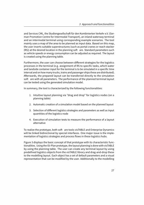
and Services CML, the Studiengesellschaft für den Kombinierten Verkehr e.V. (Ger-man Promotion Centre for Intermodal Transport), an inland waterway terminaland an intermodal terminal using corresponding example scenarios. The toolmainly uses a map of the area to be planned as input data. Based on this map,the user inserts suitable superstructures (such as portal cranes or reach stacker(RS)) at the desired location in the planning soft are. Standard parameters suchas vehicle speeds or energy consumption can be adjusted as required. The layoutis created using the planning table.
Furthermore, the user can choose between different strategies for the logisticsprocesses in the terminal (e.g. assignment of RS to specific tasks, which waterand landside container input for the terminal is to be simulated in a specific timeinterval andonhowmany trucks, trains andpassenger ships thesearedistributed).Afterwards, the prepared layout can be transferred directly to the simulationsoft are with all parameters. The performance of the planned terminal layoutcan be tested using the generated simulation model.
In summary, the tool is characterized by the following functionalities:
1. Intuitive layout planning via ”drag and drop” for logistics nodes (on aplanning table)
2. Automatic creation of a simulation model based on the planned layout
3. Selection of different logistics strategies and parameters as well as inputquantities of the logistics node
4. Execution of simulation tests to measure the performance of a layoutalternative
To realize the prototype, both soft are tools visTABLE and Enterprise Dynamicswill be linked bidirectional by special interfaces. One major issue is the imple-mentation of logistics strategies and process flows in these logistics hubs.
Figure 3 displays the basic concept of that prototype with its characteristic func-tionalities. Using the ISI-Planprototype, the layoutplanning is donewith visTABLEby using the planning table. The user can create any terminal layout by usingpredefined logistics objects from the visTABLE library and drag-and-drop theseto the modelling layout. Each object has a set of default parameters and a visualrepresentation that can bemodified by the user. Additionally to themodelling
27
Integrating Layout Planning and Simulation for Logistic Nodes
of the layout in visTABLE the user also defines the logistics strategies and pro-cesses to be used later on in the simulation model and defines the target valuesto measure the performance of the layout.
When themodelling process is finished in visTABLE all data is transferred to Enter-prise Dynamics. The simulation tool then automatically creates the simulationmodel with all applied objects, parameters and additional settings and automat-ically runs the defined simulation experiments. The defined target values aremeasured during each simulation run and are stored in a database. After thesimulation experiments the result data is returned to visTABLE where the usergets these results presented in the form of e.g. diagrams and tables.
28

3 Approach and functionalities
Figure 2: Overview of the functionalities of the prototype
29

Integrating Layout Planning and Simulation for Logistic Nodes
4 System specification
As mentioned beforehand, the system specification defines which objects, pro-cesses and strategies, relevant problems and output parameters should be in-cluded in the new soft are tool. All of these issues are presented in the followingsection.
4.1 Objects
In the following, relevant objects and correspondingparameters for the integratedsoft are are described. The objects are grouped in five categories: vertical trans-port, horizontal transport, external vehicles andmeans of transport, loading units(LU), terminal areas.
The category vertical transport comprises terminal equipment whose main func-tion is to lift a LU from a horizontal transport vehicle or a storage area and toplace the LU on another horizontal transport vehicle or a storage area. Although,technically, a certain horizontal transport takes place, this is neglected in thiscommon classification. The pure vertical transport on terminals is carried out bycranes (e.g. gantry cranes, mobile harbor cranes).
Vehicles are assigned to the category horizontal transport if their main function isto transport LUs from one vertical transport equipment or storage area to anothervertical transport equipment or storage area. However, some equipment types,such as RS, are capable of both vertical and horizontal transport and are usedaccordingly, e.g. for unloading a LU from a truck, transporting the LU across theterminal area to a storage area and stacking the LU on other LUs in this storagearea. Within this classification, these hybrid forms are assigned to horizontaltransport. A distinction is made within this group into active and passive vehicles.Active load carriers can independently receive LU, while passive vehicles mustbe loaded by another equipment type. Examples for vehicles in this categoryare empty container handlers, reach stacker, tractor-trailer-units and shuntingengines.
While they are not classified as terminal equipment due to their deviating owner-ship, external vehicles and means of transport are nevertheless very importantobjects for the handling of goods at terminals. They are used to carry out the
30

4 System specification
incoming and outgoing volumes of LU to terminals as logistical transshipmentnodes. Examples of external vehicles are trucks, trains and barges.
Loading units are transport containers through which various goods can be trans-ported and handled in a standardizedmanner. The most important example ofthis are containers, which in turn can be divided into various subclasses such asstandard, empty, reefer, open top, tank and flat racks. Other LUs can be swapbodies and trailers.
Within the category terminal areas, almost all terminals have a paved road areain common for the arrival and departure of trucks. Furthermore, a terminal hasshunting and loading tracks. The track length for a so-called block train, i.e. atrain with the maximum permissible length, measures 750 m in Germany. Fortracks with half lengths, the block trainmust be divided and shunted. The loadingand unloading tracks are usually straddled by gantry cranes handling the LUsbetween road and rail. In larger terminals, RS are often used to support the gantrycranes. The short-term storage area for LUs is located under the crane runway.Additional storage areas can be realized in the vicinity of the crane runway andmust be operated by a RS. Administration buildings, entrance areas and fencesare also part of the terminal area category.
4.2 Processes
Terminals in general serve as transshipment points between different modesof transport. Inland waterway container terminals and intermodal transportterminals are typically part of the pre- respectively post-carriage processes ofmaritime transports. This implies that, typically, containers and other LUs arriveat these terminals by train or barge from a seaport terminal, and they are pickedupby trucks for further distribution (or vice versa). Intermodal transport terminalsare also integrated in other transport chains such as e.g. CEP (courier, expressand parcel) services.
Usually, allmain cargo handling processes on the terminal beginwhen an externalvehicle arrives at the terminal with a LU and end in the short-term storage area orvice versa. However, there is also the possibility that a LU is directly transferredfrom one external vehicle (e.g. train) to another (e.g. truck) without stopping inthe storage area.
31

Integrating Layout Planning and Simulation for Logistic Nodes
Figure 3 and Figure 4 show exemplarily the processes ”pick-up by truck” and”delivery by train”. The processes were mapped on terminals of project partnersand afterwards generalized based on industry knowledge and scientific literature.They are displayed in swim lane diagrams. The darker boxes on the left show therespective actor, the medium grey boxes show the single process steps of themain process. The light grey boxes indicate the transition to othermain processes.The arrows show the order of the single process steps.
Pick-up by truck - as displayed in Figure 3 - is quite similar in all terminals. Theempty truck arrives, the driver registers either at a counter or on a self-serviceterminal, drives to a specified transfer position, is loaded with the LU by crane orRS, and afterwards leaves the terminal. In some cases, the loaded LU is checkedwhether it is the right one (if not, he LU has to be changed). Therefore, even ifdifferent equipment is used, the processes stay relatively constant.
In contrast, delivery by train varies widely depending on the equipment that isused is the train area (see Figure 4). When a train arrives, it registers, and theoffi e generates an order list for the handling equipment based on the train loadlist. If a RS is used for unloading the train, the driver unloads an accessible LU, thechecker checks the LU for damages and whether it is the right one, and then theRS transports it to the respective storage position and places it in the storage area(or on a truck that picks up the specific LU). If there are any restrictions regardingthe accessibility of the train, a shunting engine is used to shunt the rail cars. If acrane if used in the train area, the checker first checks all LUs on the train beforethe crane starts unloading. If the LU is a trailer, the crane places it directly inthe crane runway where it is picked up either by an internal tractor to be pulledto a trailer storage area or directly picked up by an external truck. If the LU is acontainer or a swap body, it is either placed in the storage area or directly on awaiting external truck. When all LUs are unloaded from the train, the order list isreturned to the offi e together with remarks from the checker.
32

4 System specification
Figu
re3:Process”
Pick-upby
truc
k”
33

Integrating Layout Planning and Simulation for Logistic Nodes
Figu
re4:Process”
Deliveryby
train”
34

4 System specification
These two process examples illustrate the challenges for a soft are tool that auto-matically generates a simulationmodel based on a static layout. The objects haveto be connected to the respective process variations. However, implementinglogistics strategies is another challenging topic.
4.3 Strategies
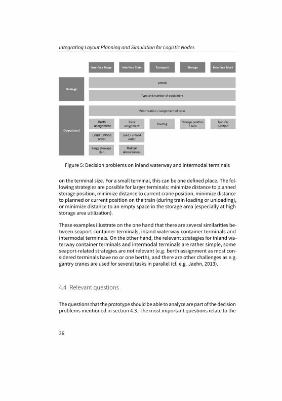
Various strategic and operational decision problems arise during the planningand operation of terminals. Strategic decision problems are of a longer-termnature and only arise infrequently, while operational decision problems occurin daily terminal operations. Figure 5 assigns strategic and operational decisionproblems to the respective terminal areas.
The strategic decision problems ”layout” as well as ”type and number of equip-ment” are essential research subjects of the soft are tool to be developed. Theoperational decision problems relate to the question of howa certain process stepis carried out, e.g. how a decision ismade, where exactly a LU is stored or towhichtransfer position a truck is steered to or which task a gantry crane performs next.The strategies can be used tomake these decisions and are therefore solutions tothe decision-making problems. For the tool to be developed, this means that forthe relevant part of the decision problems, different variants of strategies thatare typically used in terminals must be implemented. In the following, someexemplarily strategies are described.
Prioritization or assignment of tasks is about which gantry crane / RS / tractorperforms which task next. Thereby, a task is to change the location of a LU (i.e.load, store, etc. the LU from the train/truck/barge). Possible strategies include:First-come-first-served, minimize distances, minimize travel time to job startlocation, select orderwith the longestwaiting time, prioritizationof task types (e.g.train before truck), scoring strategies, or restacking / presorting at low utilization(cf. Kaff a et al., 2014; Clausen and Kaff a, 2016; Eckert et al., 2013).
The assignment of barges to berths is only a relevant decision problem if thereis more than one berth. One possible strategy, especially with a fixed weeklytimetable, is that the assignment is always the same which means that a weeklyarriving barge always gets the same berth.
The transfer position for an external truck refers to where on the terminal thetruck hands over or receives the LU. The strategy depends among other things
35
Integrating Layout Planning and Simulation for Logistic Nodes
Figure 5: Decision problems on inland waterway and intermodal terminals
on the terminal size. For a small terminal, this can be one defined place. The fol-lowing strategies are possible for larger terminals: minimize distance to plannedstorage position, minimize distance to current crane position, minimize distanceto planned or current position on the train (during train loading or unloading),or minimize distance to an empty space in the storage area (especially at highstorage area utilization).
These examples illustrate on the one hand that there are several similarities be-tween seaport container terminals, inland waterway container terminals andintermodal terminals. On the other hand, the relevant strategies for inland wa-terway container terminals and intermodal terminals are rather simple, someseaport-related strategies are not relevant (e.g. berth assignment as most con-sidered terminals have no or one berth), and there are other challenges as e.g.gantry cranes are used for several tasks in parallel (cf. e.g. Jaehn, 2013).
4.4 Relevant questions
The questions that the prototype should be able to analyze are part of the decisionproblemsmentioned in section 4.3. The most important questions relate to the
36

5 Conclusion and Future Research
storage area as well as the barge and train handling. They were identified indiscussions with different terminal experts.
Storage area-related questions are: Howmany storage lanes are required? Howlarge (length, width, height) should the storage area be? Which equipment shouldbe used and how much equipment is required by which equipment category?Which storage area organization respectively position assignment is best? Upto which storage utilization is terminal operation still productive? How do thedwell times of LUs affect the productivity of the terminal? Which order should theequipment process next?
Barge- respectively train-related questions are: What influence does the logichave on the occupancy of the tracks/ berths? Which equipment should be usedand howmuch equipment is required by which equipment category?
4.5 Output parameters
Eventually, the soft are tool has to provide output parameters that are impor-tant to decisionmakers to choose the best alternative for the specific terminal.Depending on the terminal and the question that is analyzed, different outputparameters are important. In general, the following output parameter have a highpriority to terminal decision makers: Number of LUs handled (per year/month/-day/hour), equipment utilization, utilization of space, number of delayed traindepartures, distances travelled by vehicles (per LU), and moves/h per equipment.Output parameters with a medium priority are e.g. cycle time of (sub-)processes,duration of the train’s stay at the terminal, fuel consumption, power usage, per-sonnel expenses, equipment wear, and noise emissions.
5 Conclusion and Future Research
This innovative soft are tool directly supports efficien and fast planning of logis-tic nodes, which are necessary for a demand-oriented expansion of the transportinfrastructure. In Germany alone there are more than 300 logistic nodes that canbenefit directly from the integrated planning and simulation tool.
Further research could extend the scope of the prototype to other logistic nodesand even seaport container terminals. It could also include additional objects,
37

Integrating Layout Planning and Simulation for Logistic Nodes
processes and strategies. Also new technologies could be testedmore easily aswell as time and cost efficientl .
Financial disclosure
This work was funded by the German Federal Ministry of Education and Research(BMBF) as part of the research project ”ISI-Plan - Integration von ereignis-diskreterLogistiksimulation und Layoutplanung für logistische Knoten “.
References
Angeloudis, P. and M. G. Bell (2011). “A review of container terminal simulation models”. In: 38.5,pp. 523–540.
Böse, J. W., ed. (2011). Handbook of Terminal Planning. Operations Research/Computer ScienceInterfaces Series. New York, NY: Springer New York.
Brinkmann, B. (2005). Seehäfen - Planung und Entwurf. Berlin: Springer.Canonaco, P., P. Legato, R. M. Mazza, and R. Musmanno (2008). “A queuing network model for the
management of berth crane operations”. In: 35.8, pp. 2432–2446.Clausen, U. and J. Kaff a (2016). “Development of priority rules for handlings in inland port
container terminals with simulation”. In: 10.2, pp. 95–102.Dai, J., W. Lin, R. Moorthy, and C.-P. Teo (2004). Berth Allocation Planning Optimization in Container
Terminals: Working Paper. Atlanta, USA.Dangelmaier, W., C. Laroque, and A. Klaas, eds. (2013). Simulation in Produktion und Logistik
2013: [Entscheidungsunterstützung von der Planung bis zur Steuerung ; 15. ASIM Fachtagung]; Paderborn, 09. - 11. Oktober 2013. Vol. 147. ASIM-Mitteilung. Paderborn: Heinz-Nixdorf-Inst.Univ. Paderborn.
Dragović, B., E. Tzannatos, and N. K. Park (2017). “Simulationmodelling in ports and containerterminals: Literature overview and analysis by research field, application area and tool”. In:29.1, pp. 4–34.
Duinkerken, M. B., R. Dekker, S. T. G. L. Kurstjens, J. A. Ottjes, and N. P. Dellaert (2007). “Comparingtransportation systems for inter-terminal transport at the Maasvlakte container terminals”. In:Container terminals and cargo systems: design, operations management, and logistics controlissues. Ed. by K. H. Kim and H.-O. Günther. Berlin: Springer, pp. 38–61.
Eckert, C., P. Teitge, andD.Steinhauer (2013). “BausteinbasierteSimulationdesLadungsumschlagsin trimodalen Contai-nerterminals”. In: Simulation in Produktion und Logistik 2013. Ed. by W.Dangelmaier, C. Laroque, and A. Klaas. Vol. 147. ASIM-Mitteilung. Paderborn: Heinz-Nixdorf-Inst.Univ. Paderborn, pp. 283–292.
Garro, A., M. F. Monaco,W. Russo, M. Sammarra, andG. Sorrentino (2015). “Agent-based simulationfor the evaluation of a new dispatching model for the straddle carrier pooling problem”. In:91.2, pp. 181–202.
38

REFERENCES
Guo, X. and S. Y. Huang (2012). “Dynamic Space and Time Partitioning for Yard Crane WorkloadManagement in Container Terminals”. In: 46.1, pp. 134–148.
He, J., Y. Huang, andW. Yan (2015). “Yard crane scheduling in a container terminal for the trade-offbetween efficien y and energy consumption”. In: 29.1, pp. 59–75.
Jaehn, F. (2013). “Positioning of loading units in a transshipment yard storage area”. In: 35.2,pp. 399–416.
Kaff a, J., U. Clausen, and S. Stein (2014). “Revealing gaps in the material flow of inland portcontainer terminals alongside the danube with simulation”. In:Winter Simulation Conference(WSC), 2014. Ed. by A. Tolk. Piscataway, NJ and Piscataway, NJ: IEEE, pp. 1807–1818.
Kemme, N. (2012). “Effects of storage block layout and automated yard crane systems on theperformance of seaport container terminals”. In: 34.3, pp. 563–591.
Kim, K.H. andH.-O. Günther, eds. (2007).Container terminals and cargo systems: design, operationsmanagement, and logistics control issues. Berlin: Springer.
Liu, C.-I., H. Jula, and P. A. Ioannou (2002). “Design, simulation, and evaluation of automatedcontainer terminals”. In: 3.1, pp. 12–26.
Rabe, M., ed. (2008). Advances in Simulation for Production and Logistics Applications.Rabe, M., ed. (2012). Advances in Simulation for Production and Logistics Applications.Tao, J. and Y. Qiu (2015). “A simulation optimization method for vehicles dispatching among
multiple container terminals”. In: 42.7, pp. 3742–3750.Tolk, A., ed. (2014).Winter Simulation Conference (WSC), 2014. Piscataway, NJ and Piscataway, NJ:
IEEE.Toth, M., A. Wagenitz, and S. Turgut (2008). “Ein Ansatz zur kollaborativen, modellbasierten Pla-
nung von Komponenten mit Hilfe von elektronischen Katalogen (eKAT)”. In: Advances in Simu-lation for Production and Logistics Applications. Ed. by M. Rabe, p. 417.426.
Wurdig, T. J. and R.Wacker (2012). “Generische Simulationslösung für Fördertechnik”. In: Advancesin Simulation for Production and Logistics Applications. Ed. by M. Rabe, pp. 12–20.
Xin, J., R. R. Negenborn, and G. Lodewijks (2014). “Energy-aware control for automated containerterminals using integrated flow shop scheduling and optimal control”. In: 44, pp. 214–230.
39