integrating human related errors with technical errors to...
TRANSCRIPT

Safety Science 63 (2014) 179–190
Contents lists available at ScienceDirect
Safety Science
journal homepage: www.elsevier .com/locate /ssc i
Integrating human related errors with technical errors to determinecauses behind offshore accidents
0925-7535/$ - see front matter � 2013 Published by Elsevier Ltd.http://dx.doi.org/10.1016/j.ssci.2013.11.009
⇑ Corresponding author. Tel.: +47 918 97 303.E-mail addresses: [email protected] (P. Skalle), [email protected] (A.
Aamodt), [email protected] (K. Laumann).
Pål Skalle a,⇑, Agnar Aamodt b, Karin Laumann c
a Department of Petroleum Engineering and Applied Geophysics, Norwegian University of Science and Technology, NTNU, NO-7491 Trondheim, Norwayb Department of Computer Science and Information Technology, Norwegian University of Science and Technology, NTNU, NO-7491 Trondheim, Norwayc Department of Psychology, Norwegian University of Science and Technology, NTNU, NO-7491 Trondheim, Norway
a r t i c l e i n f o
Article history:Received 15 March 2013Received in revised form 6 November 2013Accepted 8 November 2013
Keywords:Organizational safetyAccidentHuman factorOil well drillingTechnical errorHuman errorOntologyKnowledge engineering
a b s t r a c t
This paper presents how to model technical and human errors and how the two error types are integratedin one common model. Human errors were modeled as an integral part of the organization’s ability tohandle failures, while technical errors were embedded as an integral part of the oil well drilling opera-tion.
To reduce the number of offshore accidents there is a continuous focus on safety improvements. Animproved evaluation method is therefore suggested, a method which has the potential of being run inreal-time to obtain an immediate assessment of the failure. The method is based on a knowledge modelof the oil-well drilling process. All concepts in the model are structured in hierarchical categories, basedon well-established knowledge, combined with situation specific experiences. We have previously devel-oped a modeling tool for technical failures during drilling. Obviously the human factor plays an importantrole in all accidents. However the combination of technical and human factors has not yet been reported.Human factors have therefore been integrated with existing technical concepts in the present methodol-ogy.
Our tool has the capability to point out the most probable causes behind failures by relating incidentobservations to failures. The tool has proven its capability of pointing out the most probable technical andhuman related causes behind accidents in the petroleum sector. The present version points out theunderlying causes, a future version is planned to also offer a suggestion of remedial countermeasures.
� 2013 Published by Elsevier Ltd.
1. Introduction
Human errors are practically always involved in accidents. Con-tinuous efforts to reduce human errors have placed increasedemphasis on training, motivation, hardware design, and manage-ment systems. This has contributed to improved safety perfor-mance in the industry, clearly demonstrated through statisticalstudies, for example the one from the Swedish Rescue and ServiceAgency (SRS, 2010), as shown in Fig. 1.
The number of fatalities is, however, not an indicator of techni-cal failures. In spite of improved safety awareness and improvedtechnology, the increased challenging environment accompaniedby increased technically challenging wells has not lead to anaccordingly decrease of non-productive time (NPT) during oil-welldrilling. NPT exhibits a much lower declining trend than number offatalities. In exploration and development drilling, 5–15% of thedrilling time is spent on unproductive downtime caused by opera-
tional failures that involve human errors, such as stuck pipe, mudlosses, and well control incidents (Halliburton Solving Challenge,2012).
To counteract the problem of too high NPT the industry isspending much effort in understanding, modeling and counteract-ing technical failures (Dean, 2012; Uniport et al., 2012). Similarly,from an organizational point of view, also huge efforts are beingundertaken to improve the NPT, e.g. Thomassen and Sørum(2002) and Bunn et al. (2010). In addition to internal and externalaccident investigations, modeling work is continuously improving.
Previously, accident analyses revealed factors that were relatedto the operator performing the task. Today however, the focus hasshifted to organizational factors, such as management and safetyculture, which form many of the conditions that the operatorswork under, like training, staffing and high work pressure.
Disasters are rarely caused by only one factor. Reason (1990)suggested that there is an analogy between latent errors in com-plex technical systems and latent pathogens within the humanbody (pathogens lead to deceases). The pathogen theory has ledto a search for pre-disease or pre-accident indicators, assumingthey are remediable. The safety culture of an organization includes

Fig. 1. Workplace fatalities in Sweden during the last 50 years (SRS, 2010).
180 P. Skalle et al. / Safety Science 63 (2014) 179–190
all issues involving human and technical safety aspects. Severalcompanies, e.g. Tripod (Sharp et al., 2004) and The Energy Institute(EI, 2010) have suggested factors or indicators related to organiza-tional safety. These approaches were adopted in the research pre-sented in the present paper.
Human reliability analysis (HRA) methods are used to quantifythe likelihood of human errors in major accidents. The authors ofthese methods also claim that the methods could be used for ret-rospective analysis of accidents. However, a problem by usingthese methods in such a way is that they only include factors thatare close to the performing operators and that they do not includefactors on the organizational level such as management and orga-nizational safety culture factors.
The overall evaluation capabilities will be improved by combin-ing all contributing factors involved in accidents, as illustrated inFig. 2. Our approach is based on knowledge modeling principlesapplied in the CREEK tool (Aamodt, 2004). The original tool wasdeveloped in the 1990s (Aamodt (1994) for the purpose of decisionsupport by reasoning from past experiences, referred to as case-based reasoning (CBR). Technical failures and their causes have al-ready been modeled (Skalle et al., 2013). CREEK has also been thebasis for a commercial system for prediction in the oil well domain,developed and successfully tested by Verdande Technology, a spin-off company from our university (Gundersen et al., 2012). Now thetime has come to integrate human errors with technical errors.
The main contributions of this paper are:
� A new knowledge model related to human error.� An extension of CREEK’s built-in ontology to encompass both
technical and human errors integrated in a complete organiza-tional model.
Our approach will enable prediction of failures before they oc-cur, and if they occur, enable solving them more efficiently byrevealing the root causes behind the failures.
We claim that the usefulness of the expanded and upgradedmethod will be enhanced compared to state-of-the-art of accidentinvestigations.
Execute
AccidentPlan
Evaluate
Organizational Safety SystemBarriers
H&Orgerror
Techni-cal error
Fig. 2. Three contributing factors involved in an accident: Human & Organizational(H & Org) Error, Technical Error and the resulting Organization Safety Level.Rectangles represent activities, circles represent occurrences.
2. Extended method applied to enhanced investigation ofaccidents
2.1. Knowledge engineering
The model of drilling-related knowledge developed as part ofthis research is based on the adaptation of established methodsand best practice for knowledge model development – also re-ferred to as knowledge engineering. The term ‘‘knowledge’’ – asused in this paper – refers to all types of explicitly representedstructures on the basis of which a system is able to perform reason-ing. A sound principle in knowledge engineering is that the result-ing model should be described at a conceptual level, independentof computer implementation issues such as programming lan-guages and computer size.
Established results from the knowledge acquisition and model-ing community have produced several methodologies and tech-niques for describing knowledge at the conceptual,implementation-independent level. Influential earlier examplesare the Components of Expertise framework (Steels, 1990), andthe CommonKADS methodology (Breuker and Van de Velde,1994). Based on these and other influential knowledge modelingmethods, a set of libraries of generic knowledge models have beendeveloped. To enable the reuse of such models, the call for com-mon generic models – more frequently referred to as ‘ontologies’– has led to the development of such generic knowledge modelswithin different application areas. Correspondingly, the term‘ontology engineering’ is now often used instead of ‘knowledgemodeling’. Examples from the area of Human Factors are Germana-kos et al. (2008) and Philippart and Karwowski (2011). A largeontology that has become an international standard is the ISO15926 oil&gas ontology (Fiatech, 2011). This ontology has beenan inspiration for our ontology, although the cover and the com-plexity of the ISO 15926 has lead us to develop our own.
Most approaches to knowledge engineering share a commonfeature: they view knowledge modeling from what is called a‘‘knowledge-level’’ perspective.Some knowledge levels are appliedas distinct levels of description of computer systems, defined to bepositioned above the level of data structures and programminglanguages. The latter is referred to as the ‘‘symbol level’’. A systemis described at the knowledge level as an agent with its own goalsand with knowledge of how to achieve its goals. The assumption isthat an agent always will use its knowledge in a way that ensuresthe achievement of its goals - provided the agent has the knowl-edge needed.
The useful thing about the knowledge level is that it enables asystem (existing or anticipated) to be described in terms of whatit does and why it does it completely independent of implementa-tion constraints. The number of knowledge modeling tools thathave been developed based on the distinction between the knowl-edge level and the symbol level have ‘operationalized’ the knowl-edge level theory by providing the necessary structures andmodeling procedures to enable the development of conceptualknowledge models of real-world systems. Most of these tools sharethe view that knowledge, in its most general form can be subdi-vided into three main categories – or viewed from three perspec-tives: Task knowledge, Method knowledge, and Domainknowledge.
Task knowledge describes what to do, usually in task-subtaskhierarchy. Tasks are tightly connected to goals and sometimes usedinterchangeably. A task is defined by the goals that a system triesto achieve. Method knowledge describes how to do it, i.e. a methodis a means to accomplish a task (e.g. to solve a problem). Domainknowledge is the knowledge a method needs about the world toaccomplish its tasks. Examples are facts, heuristics, causal relation-

Fig. 3. Knowledge perspectives.
P. Skalle et al. / Safety Science 63 (2014) 179–190 181
ships, multi-relational models, and – of course – specific cases. Fora complete model all three perspectives need to be addressed, andthe outcome of one is fed into another, typically in a iterative fash-ion (see Fig. 3). Our ontology also incorporates this three-perspec-tive view. The focus in this paper, however, is on the DomainKnowledge part of the total model.
On top of this ontology a reasoning system has been built,which enables us to combine reasoning from general domainknowledge with reasoning from situation-specific cases. Whilewe in earlier work have shown how to utilize specific cases sup-ported by general domain knowledge, in a process called knowl-edge-intensive case-based reasoning (ki-CBR) (Aamodt, 2004;Skalle and Aamodt, 2004), the work reported here focuses on themodel-based reasoning part. Our model is based on an extendedgeneral domain model in which a new sub-model of human factorshas been incorporated.
Our model of general domain knowledge consists of conceptsand relations structured in a hierarchical ontology model. Conceptsare inter-related through multiple relation types. The model can beviewed as a three-level model, as illustrated in Fig. 4: A top-levelsub-model of generic concepts, such as Physical Object, Mental Ob-ject, State and Process, a medium-level sub-model of domain-spe-cific concepts, such as Skilled-based Error, Inattention,Organizational Culture, Formation Error, Wellbore Error and Swell-ing Clay, and a bottom-level sub-model that contains specific factsand situation-specific cases. A combined top-down and bottom-upmodeling approach has been taken, by partly developing the modelfrom textbook and in-house expertise knowledge while studyingseveral existing ontologies, and partly by utilizing the specificknowledge obtained from situation-specific accidents to refineexisting and accommodate new knowledge.
At the symbol-level the model is represented as a semantic net-work, in which all concepts are interrelated within one single net-work. A syntactical regime of the ontology is that the first letter ineach word in a concept is written with capital letter, e.g. SwellingClay, while relations between concepts are written solely withsmall letters, e.g. has subclass.
In our ontology, as in most ontologies, the top-level conceptThing stands for anything in the world worth naming or character-
thing
case039
case112
case76
generic concepts
cases
domain conceptsgeneral
data
Fig. 4. Top level of the general knowledge model (ontology) on a structural form(only subclass relationships are presented) together with specific knowledge fromcases (Aamodt, 1994).
izing. Everything we want to talk about is a subclass or instance ofThing. Thing has three subclasses; Entity (an actual thing in thereal world), Descriptive Thing (a descriptions or representation ofan Entity) and Relation (a bi-directional relation between con-cepts). Examples of some subclasses are found in Table 1.
2.2. Technical error and failures in the drilling process
The drilling process enters into an error state before a failure oc-curs. Note that we have selected to classify technical errors inaccordance with location of occurrence as shown in Fig. 5, i.e.,either in the formation, the wellbore or in the equipment. This sim-ple-to-accept manner makes errors easy to classify. An error occurswhen a parameter, a process or an object exhibit a deviatoric per-formance. The deviation may rectify itself or it may be persistant,so that it leads to a failure in the long run.
By means of the knowledge model it is possible to model rathercomplex mathematical relationships. The knowledge model is notdepending on recorded parameters, it is sufficient to understandthe physics involved and model it as relationships betweenconcepts.
Failures in the drilling process are classified and presented inFig. 6. Failures are grouped in accordance with where they takeplace. Failures are the end state and the focus of accident investi-gations. The end state is a result of both technical and humanerrors.
2.3. Human error
The scientific subject referred to as human error is a sub topic ofHuman Factor. Human error is classified in accordance with thework of Rasmussen (1983) and Reason (1990) and with thosewho later trimmed and extended their work, e.g. Arnstein (1977)and Atkinson (1998). Our model represents a simplified behavioralclassification model. Fig. 7 shows the upper levels of the human er-ror hierarchy.
Human errors can in general be of the type Active Error, typi-cally associated with performance of front line operators duringexecution of a plan. The other type, Latent Error, is more underly-ing errors done by for example designers or managers that mightcontribute to active errors. Latent errors are often less apparentthan the active errors and they are in time and space more sepa-rated from an accident than the active errors. Latent errors are of-ten more hidden and difficult to find than active errors.
Human behavior is subdivided into three levels of performance(Reason, 1990), leading to three corresponding error types:
1. Skill Based Performance (Skill-B.P.): Related to automatizedbehaviors that occur without cognitive monitoring. Thistype of performance may lead to errors of type Slip andLapse
2. Rule Based Performance (Rule-B.P.): Related to misclassifi-cation of the situation. May lead to Mistake
3. Knowledge Based Performance (Knowl-B.P.): Related toapplication of stored knowledge for analytical processing.May lead to Mistake
Skill-B.P. is automatic processing, characterized by regularitiesof the past being reapplied whenever called upon. Familiar infor-mation and hands-on experience are processed rapidly. Duringsmooth, familiar, automated and non-problematic activities, mosthuman activities proceed roughly according to plan.
Rule-B.P. represent an intended action (but the intended plan iswrong), and is, together with Knowl-B.P., the most risky perfor-mance of the three since people are not easily persuaded from exe-

Table 1Examples of General Domain Concepts and their definitions.
Concept Definition
EntityProcess material Material generated or produced during the drilling processFacility All or any portion of a physical construction, including buildings, structures, equipment, roads, and so on
Descriptive ThingSynonym A descriptor with the role of connecting a term used to refer to a phenomenon, with the phenomenon concept itselfGeological description Description of faults, geological periods, geological processes, reservoirs, etc.
RelationCauses always Strength: 1.0Causes (typically) Strength: 0.9Leads to Strength: 0.8Implies Strength: 0.7Causes sometimes Strength: 0.6Enables Strength: 0.5Involves Strength: 0.5Indicates Strength: 0.4Causes occasionally Strength: 0.3Reduces effect of Strength: 0.5
Fig. 5. Subclassification of technical errors in the drilling process.
Fig. 6. Subclassification of failures in the drilling process.
182 P. Skalle et al. / Safety Science 63 (2014) 179–190
cuting an alternative plan (alternative to the wrong one). The Rule-B.P. mode is working by taking information from previous, success-ful experience, just like the functionality of cases in CBR. Rulebreaking, is seen as a contributing factor in almost all serious inci-dents. One thing is clear: People usually break rules for very goodreasons and they do not intend to create a disaster. Rule Based Mis-take (RBM) are caused by failure to apply the correct rule or, ex-pressed in another way, applying an inappropriate rule, causedby misclassification of the problem. Rule Based Mistake is less
frequent than skill based slips/laps, but more dangerous and moredifficult to detect.
Knowl-B.P. comes into play when the Rule-B.P. repertoire is ex-hausted, triggered by changes in the routines, i.e. during well plan-ning and during handling of critical situations. In this situation,work must be done ‘‘on-line’’, using conscious processing withfeedback. Discrete information processing elements are; retrieve;transform; extend; and recombine. Humans sometimes do slipsand lapses. The operators’ tasks are both rule based and knowledge

Fig. 7. Human errors are classified as either active (Intentional and non-intentional Behavior) or latent (Unintentional Behavior). Each arrow represents the relation ‘hassubclass’.
P. Skalle et al. / Safety Science 63 (2014) 179–190 183
based. To follow a procedure might be both rule based and knowl-edge based. Procedures do not always specify the work itself andthat following procedures need a lot of judgment to adjust the pro-cedure to specific situations with regards to for example timing ofsubtask, relevance, importance and prioritization. To follow proce-dures might be both Rule-B.P. and Knowledge-B.P.
Knowl-B.P. resembles the ki-CBR process. Both processes needcases, experience and intelligent processing.
2.4. Organizational safety error
Latent errors are associated with the safety level of the orga-nization and are often committed by its designers, its high leveldecision makers and by its managers. These errors are the great-est threat to safety of complex systems. The active errors areindirectly inherited from latent errors in the organization. Spot-ting latent errors is the way to find the root causes of failures. Inthe latent error view (pathogen metaphor) presented by Reason(1990), the organization and its systems, rather than individuals,are assessed, leading to a search for indicators of organizationalreliability.
Accidents will only occur when a sufficient number of barriersfail (Craddock, 2004). The condensate explosion on the North Seaoil platform Piper Alpha has often been used to illustrate this.When problems were encountered with the main condensatepumps, the operator switched to the back-up pumps where a reliefvalve was missing and there was no protection against condensateignition, which again was a result of three factors; inadequatework permit, knowledge gaps of the procedure and communica-tion breakdown of equipment status between shifts. This caseillustrates how a combination of factors, including hardware andhuman errors, can combine to allow a serious incident to occur.Our tool is being based on such type of relationships and thus pos-sesses the ability of revealing the combined row of events.
In Fig. 8 we have modeled factors in groups which are in com-mon use today (EI, 2010). In addition we have suggested logicalsubclasses of the main factors. The factors will function as failuretokens or organizational safety indicators.
To make the intention behind each concept clear and thus avoidconfusion, conceptual classification is implicitly included in CREEKthrough concept definitions. In case of disputes, the concept can beadjusted or extended. As example of a concept definition we pickout, from level two in the model, the concept of Safety CriticalCommunication (EI, 2010):
‘‘Reliable and accurate two-way communication (spoken andwritten) of safety–critical or safety-related information havemany routes, for example between control room and field oper-ators, between operators within a shift and at shift hand-over,and not the least from the management to all employees. The
feedback loops, including indicators and other relevant infoconstitute the Safety Info System (SIS)’’.
There are many factors that contribute to human errors. Someof the factors are representing the front-end operator through fac-tors like Fatigue, Boredom, Inattention and Stress. Other factorsmight be task-specific such as Complexity, Training, Proceduresand Human Machine Interaction, while other factors are more atthe organizational levels such as Staffing, Management and SafetyCulture. All these factors are included in the model, and most ofthem are present in Fig. 8.
Human and organizational errors are closely coupled. In Fig. 2and in the remaining of the paper they are referred to as Human& Organizational (H & Org) errors.
3. Implementing the methodology
Based on the theoretical description in Chapter 2 the methodol-ogy will be implemented in seven separate steps:
Step 1: Develop the Creek platform.Step 2: Expand the ontology into the new knowledge domain ofHuman Factor.Step 3: Retrieve relevant findings appearing before and up tothe time of the accident.Step 4: Translate findings into acceptable symbolic concepts.Step 5: Enter the concepts at their logical location in the knowl-edge model.Step 6: Relate concepts through cause-effect relationships.Step 7: Test the improved method with data from field cases.
Step 1 has been presented previously by Aamodt (1994, 2004).This step also includes the technical part of the ontology (Skalleand Aamodt, 2004). Step 2 is presented in Chapter 2. At the onsetof developing a new knowledge domain, the ontology is built onthe basis of formal knowledge settled in renowned literature, andis referred to as top-down modeling.
The remaining four steps involve the insertion of new findings(observations and relevant facts) from major accidents; bottoms-up modeling. In these four steps we have exemplified the methodby referring to a real case to make the method easier to follow.
Fig. 9 represents the process of developing these four steps ofthe method, which are presented next:
Step 3: Retrieve findings. To exploit the accident in Well P-01A(the well-name is made anonymous) all relevant pre-accidentobservations were collected. Observations made during and afterthe time of occurrence cannot be applied for prediction of theaccident.
Well P-01A was a challenging well characterized by narrowmud margins. The selected incident was initiated by a kick (an in-

Fig. 8. Latent errors are contributors of organizational safety indicators. The 8 error types and 22 subclasses are related to unintentional behavior. Each arrow represents therelation ‘has subclass’.
MajorAccident
Technical FailuresDesign Errors
Procedures
Evaluation of Technical Failure and H & Org Error
Indicators
Observation types
OperatorManagementLine ManagementDesign Factors
Technical ErrorHuman ErrorFormation Related ErrorEquipment Error
Important Internal ConceptsOperational parametersTecnical parametersIndicatorsHuman related to:
Fig. 9. The process of how to determine failures and the organizational challenges after a major accident is also an indication of how the method must be modeled.
20" csg at 1420 mMD
13 3/8 ” csg at 1487 mMD
13 ½ ” hole at 2624 mMD / 1724 mTVD
12 ½ ” hole at 2664 mMD / 1740 mTVD
Top Balder at 2226 mMD / 1577 mTVD
Top Hordaland at 1774 mMD / 1360 mTVD
Top Lista 1739 mTVD
Top Shetland 1746 mTVD
Motherwell
Fig. 10. Wellbore geometry of P-01A at the time of the accident (Utvik, 2010).
184 P. Skalle et al. / Safety Science 63 (2014) 179–190
flux from the geological formation) during drilling. A kick in itself isnormally routinely handled and classified as an ordinary failure,not a major one. However, the later killing operation was complexand time consuming. Since handling of the kick involved seriousoperational deviations, requiring five days of repair actions andending with plugging and abandoning the well, the case wasviewed as a major accident.
Originally P-01 was drilled in 1991 and set on production thesame year. During oil production the pressure gradually rose to140 bars in the 13 3/800 and 9 5/800 annulus. The Cement BondLog that was run after cementing the 9 5/800 casing in 1991 indi-cated very poor bonding and even partly free 9 5/800 casing (notcompletely cemented). The annulus was later squeeze cemented.Planning of a sidetrack (P-01A) began in 2008. The mother well,P-01, was plugged back in November 2009, and the sidetrackwas initiated the same year, milled out through the 13 3/800 casingat 1791 mMD (measured depth). The upper part of the new well,the 12 ½ ⁄ 13 ½00 section, was drilled in overbalance of the porepressure in the sedimentary formation.
Three gas tops came with the returning mud from 2469 to 2524mMD during drilling. While drilling into the formation called Lista,from 2640 mMD, the returning mud’s gas concentration was 8%.Fig. 10 presents the wellbore at this stage of the operation. Aftera flow check at 2665 mMD, 700 l flowed freely from the sedimentsover a period of 15 min. The well was closed and killed by means ofthe Driller’s killing method, but technical problems continued forseveral days.
The case is defined through deviatory performance (comparedto a normal process progress) both during the planning and theexecution phase. The Norwegian Petroleum Inspection Agency (Pe-Til) kept a tight focus on deviations brought about by the operating

P. Skalle et al. / Safety Science 63 (2014) 179–190 185
organization and its safety culture (Solheim et al., 2010; Etterlidand Gundersen, 2010). One of PeTil’s general goals of supervisingis to make sure that the parties involved in the petroleum industrykeep a high HSE performance level. PeTil has specifically beenfocusing on drilling in depleted reservoirs due to many incidentsin such challenging areas. Incident investigation performed bythe operating company focused more on technical factors (Utvik,2010; Førsund et al., 2010). During the investigation of the accidentPeTil reported on transparent conditions and good communicationwith the operating company.
Step 4: Case observations on symbolic form. The technical, humanand organizational (H & Org) related observations have been struc-tured to fit the grammar of the knowledge model and made intoapplicable symbolic concepts, characterized by being short andunambiguous expressions, applicable and reusable for any acci-dent. The complete case, from its beginning in 1991 to date ofthe blowout, is presented in the Appendix. Some of the observa-tions made during the critical period, just before the kick, are pre-sented in Fig. 11.
Step 5: Enter concepts into the knowledge model. The next stepwas to place new concepts in the knowledge model. Most of thetechnical concepts were already inherent in our model, while H& Org related concepts were not. Fig. 6 above and Table 2 demon-strate the results of this step.
Step 6: New relationships developed from new case observations.In this step the new case observations were related in meaningfuland logical relationships to any relevant concept in the existingknowledge model. New concepts make our knowledge modelgrow. Some of the observations were already inherent in the mod-el, entered during previous failure cases. In Table 3 a selected num-ber of concepts demonstrate normal and bi-directionalrelationships.
Deviations from normal behavior before and during the acci-dent will be related, either directly or through longer paths, tothe failure. Some relationships, shown in Table 3, exemplify howmodel works.
The examples in Table 3 demonstrate that not much can bedone about slips, lapses and inattention, performed by the front-line operators, besides offering good training and practicing goodsafety culture.
4. Field test (Step 7)
The flow of information during the testing of the model is indi-cated in Fig. 9. An accident induces observations which point atirregular system states, thereafter to errors, and finally to thefailures and to the weak spots in the organization expressedthrough Organizational Error Indicators.
Fig. 11. Some of the observations are found in the real-time drilling data. CorrespondinTechnical observations immediately before the accident). The kick occurred at 11:00.
4.1. Identifying causal paths
In order not to make the presentation too large and complicatedwe present technical and human related observations separately.The H & Org Error Indicators that were activated during the testare presented in Fig. 12.
In Fig. 13 a detail is shown. The observations which activatedthe H & Org Error Indicator called Fatigue & Work Load are pre-sented, including the relation names. Such details enable us to esti-mate the relation strength between observations and indicators(see next chapter).
Now to the other observation-type, the technical one. In Fig. 14a similar view as for the H & Org errors above is presented; whichof the technical error/failure were activated by technical observa-tions. Not surprisingly the observations pointed mainly at the fail-ure Kick (which occasionally causes a Blowout).
4.2. Strengths of causal paths
After the introductory presentation of the two observationtypes, the main objective of the study remains;
1. Is it, on the basis of human and organizational related observa-tions, possible to point out weaknesses in the organization? 28observations are H & Org related and are pointing at critical H &Org Error Indicators.
2. Is it, on the basis of all observations, both H & Org and technicalrelated, possible to point out the most probable failure typewhich is about to occur? 22 of the H & Org related observationsare pointing at the correct Failure called Kick, via TechnicalError, and thereby strengthening the technical relatedobservations.
In general, the strength of each single path is the product of thestrength of all n relations leading from the observation to the targetindicator or target failure:
Path strength ¼ Pi¼1�>n ðrelation strengthiÞ ð1Þ
When there are several explanatory paths pointing to the sameindicator/failure, their total explanation strength is determined byadding path strengths:
Explanation strength ¼X
j¼1�>m
ðpath strengthjÞ ð2Þ
Here m is the number of paths. Calculated explanation strengthswill be a good measure of indentifying the most probable indicator.
To exemplify the two equations we apply the details alreadypresented in Fig. 13. Here it is shown that 6 observations arepointing to the Management Related Fatigue Factor. The obtained
g observations are also shown on symbolic form in Appendix 1 under the heading:

Table 2Two selected (of totally 8) Human & Organizational Error (H & Org) Error Indicators with their 5 (of totally 22) subclasses (hsc = has subclass) are presented here with one moresubclass level. The latter level (to the right) is represented by observations.
H & Org Error Indicator hsc hsc
Organizational Culture Safety Culture ⁄Ignorance Of culture⁄Inadequate safety plan⁄Inadequate audit procedure⁄Own requirement not complied with⁄Inadequate peer assist and peer review⁄Risk workshop not held⁄Management too little involved during killing⁄More vacation than normal during Christmas⁄Sister organization were under-utilized
Guiding Safety Principle ⁄Little gratitude to coworkers⁄Co-workers view not listened to⁄Low reward culture for error discovery⁄Risk form inadequately filled in⁄Document neither signed nor dated⁄Conflicting goals/standards⁄Confusing directions⁄Unclear what was expected
Design Error Planning Error Inadequate planning of challenging wellboreEquipment Design Error ⁄Inadequate warning systems
⁄Inadequate devices⁄Inadequate engineering design
Labeling Error ⁄Too many info-systems⁄Misleading labeling⁄Poor design of alarm system
Table 3Selected relationships, new and existing ones, between observation and model-internal concepts.
Inadequate Training leads to Lack Of CompetenceLack Of Competence causes sometimes Slips and LapsesSlips and Lapses causes occasionally Technical ErrorEquipment Failure is involved by Inadequate MaintenanceUnderbalanced Pressure is implied by Increased Mud Gas Level
186 P. Skalle et al. / Safety Science 63 (2014) 179–190
results after activating the two equations are expressed in Table 4.The explanation strength of these 6 paths are pointing atManagement Related Fatigue Factors with a strength of 2.07. Thetotal explanation strength of all the 40 observations were32.6, thus translating the explanation strength to 2.07/32.6
Fig. 12. H & Org Error Indicators: Cause-effect paths leading from observations (far left)only two of them are examplified here. Only around 25% of all the 28 observations are t
100 = 6.35% of all human related observations. This number is indi-cated with a circle in Fig. 15 in the next chapter.
4.3. Resulting causal pattern (set of paths)
The final results are presented in Fig. 15 and in Table 5. Fig. 15presents the activated H & Org Error Indicators, while Table 5 pre-sents the probable end-state (Failure) of all observations.
Resulting findings from our method do not differ much from themain findings of the other accident-investigations (Førsund, 2010;Solheim et al., 2010). Procedures and Organizational Culture wouldprobably also be the main indicators through competing methods.However, we claim that the results obtained through our method-ology enable an improved causal specification, revealed immedi-ately after failures, due to these facts:
to weak points in the organization (right). Of the totally 8 H & Org Error Indicatorsherefore presented in this figure. Each arrow represents the relation ‘has subclass’.
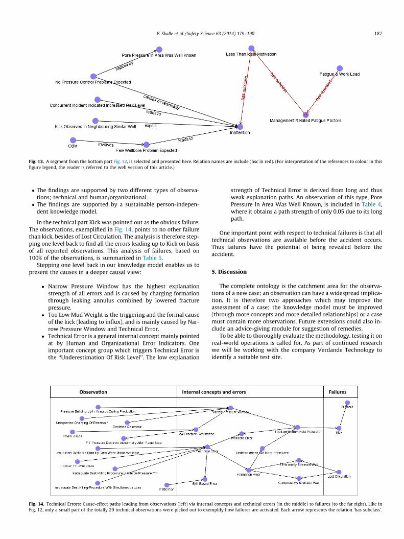
Fig. 13. A segment from the bottom part Fig. 12, is selected and presented here. Relation names are include (hsc in red). (For interpretation of the references to colour in thisfigure legend, the reader is referred to the web version of this article.)
P. Skalle et al. / Safety Science 63 (2014) 179–190 187
� The findings are supported by two different types of observa-tions; technical and human/organizational.� The findings are supported by a sustainable person-indepen-
dent knowledge model.
In the technical part Kick was pointed out as the obvious failure.The observations, exemplified in Fig. 14, points to no other failurethan kick, besides of Lost Circulation. The analysis is therefore step-ping one level back to find all the errors leading up to Kick on basisof all reported observations. This analysis of failures, based on100% of the observations, is summarized in Table 5.
Stepping one level back in our knowledge model enables us topresent the causes in a deeper causal view:
� Narrow Pressure Window has the highest explanationstrength of all errors and is caused by charging formationthrough leaking annulus combined by lowered fracturepressure.
� Too Low Mud Weight is the triggering and the formal causeof the kick (leading to influx), and is mainly caused by Nar-row Pressure Window and Technical Error.
� Technical Error is a general internal concept mainly pointedat by Human and Organizational Error Indicators. Oneimportant concept group which triggers Technical Error isthe ‘‘Underestimation Of Risk Level’’. The low explanation
Fig. 14. Technical Errors: Cause-effect paths leading from observations (left) via internaFig. 12, only a small part of the totally 29 technical observations were picked out to exe
strength of Technical Error is derived from long and thusweak explanation paths. An observation of this type, PorePressure In Area Was Well Known, is included in Table 4,where it obtains a path strength of only 0.05 due to its longpath.
One important point with respect to technical failures is that alltechnical observations are available before the accident occurs.Thus failures have the potential of being revealed before theaccident.
5. Discussion
The complete ontology is the catchment area for the observa-tions of a new case; an observation can have a widespread implica-tion. It is therefore two approaches which may improve theassessment of a case; the knowledge model must be improved(through more concepts and more detailed relationships) or a casemust contain more observations. Future extensions could also in-clude an advice-giving module for suggestion of remedies.
To be able to thoroughly evaluate the methodology, testing it onreal-world operations is called for. As part of continued researchwe will be working with the company Verdande Technology toidentify a suitable test site.
l concepts and technical errors (in the middle) to failures (to the far right). Like inmplify how failures are activated. Each arrow represents the relation ‘has subclass’.
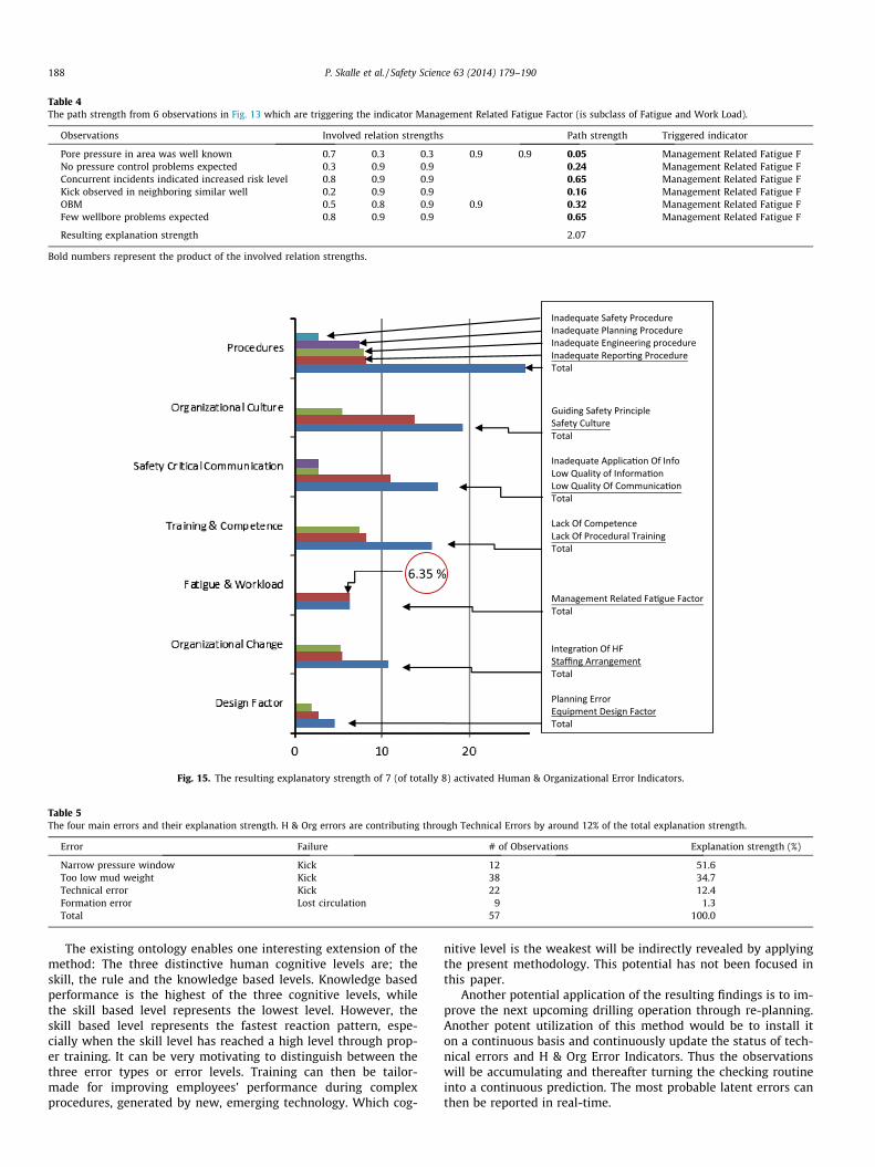
Table 4The path strength from 6 observations in Fig. 13 which are triggering the indicator Management Related Fatigue Factor (is subclass of Fatigue and Work Load).
Observations Involved relation strengths Path strength Triggered indicator
Pore pressure in area was well known 0.7 0.3 0.3 0.9 0.9 0.05 Management Related Fatigue FNo pressure control problems expected 0.3 0.9 0.9 0.24 Management Related Fatigue FConcurrent incidents indicated increased risk level 0.8 0.9 0.9 0.65 Management Related Fatigue FKick observed in neighboring similar well 0.2 0.9 0.9 0.16 Management Related Fatigue FOBM 0.5 0.8 0.9 0.9 0.32 Management Related Fatigue FFew wellbore problems expected 0.8 0.9 0.9 0.65 Management Related Fatigue F
Resulting explanation strength 2.07
Bold numbers represent the product of the involved relation strengths.
Fig. 15. The resulting explanatory strength of 7 (of totally 8) activated Human & Organizational Error Indicators.
Table 5The four main errors and their explanation strength. H & Org errors are contributing through Technical Errors by around 12% of the total explanation strength.
Error Failure # of Observations Explanation strength (%)
Narrow pressure window Kick 12 51.6Too low mud weight Kick 38 34.7Technical error Kick 22 12.4Formation error Lost circulation 9 1.3Total 57 100.0
188 P. Skalle et al. / Safety Science 63 (2014) 179–190
The existing ontology enables one interesting extension of themethod: The three distinctive human cognitive levels are; theskill, the rule and the knowledge based levels. Knowledge basedperformance is the highest of the three cognitive levels, whilethe skill based level represents the lowest level. However, theskill based level represents the fastest reaction pattern, espe-cially when the skill level has reached a high level through prop-er training. It can be very motivating to distinguish between thethree error types or error levels. Training can then be tailor-made for improving employees’ performance during complexprocedures, generated by new, emerging technology. Which cog-
nitive level is the weakest will be indirectly revealed by applyingthe present methodology. This potential has not been focused inthis paper.
Another potential application of the resulting findings is to im-prove the next upcoming drilling operation through re-planning.Another potent utilization of this method would be to install iton a continuous basis and continuously update the status of tech-nical errors and H & Org Error Indicators. Thus the observationswill be accumulating and thereafter turning the checking routineinto a continuous prediction. The most probable latent errors canthen be reported in real-time.

P. Skalle et al. / Safety Science 63 (2014) 179–190 189
One important advantage of the present tool: Whenever a newaccident occurs it may result in new concepts, new observationsand new relationships. New knowledge is imbedded in the modeland thus making it a tool which learns; it becomes upgraded bythe most recent knowledge.
6. Conclusion
Technical and Human & Organizational Error have been mod-eled as an ontological hierarchy. The causes behind a failure weredetermined by identifying paths of relations from the observationsto any potential errors, leading to the failures.
The tool was tested on one major accident during oil-well dril-ling operations. The test resulted in:
– The weakest Technical and Human & Organizational Indicatorwere revealed.
– The causes behind the indicators were revealed.– The tool has the potential of predicting accidents before they
occur.– The tool is learning and upgrading itself while being used.
We need to include more cases and more observations to in-crease both the accuracy and the trustworthiness of the results.We plan to explore more of the tool’s capabilities. Although accu-racy is sacrificed for probability in the knowledge model, this couldat the same time be the strength of the model: Complex mathe-matical expression can be expressed through logical, probabilisticrelationships.
Acknowledgements
We would like to thank Tor Busch for many suggestions relatedto organizational behavior. Thanks also to the Petroleum Inspec-tion Agency of Norway (PeTil) for searching up all relevant docu-ments and information in their data bases, and to VerdandeTechnology for granting permission to use their knowledge editor.NTNU has been the sole funding body of the present research.
Appendix A
All the case observations related to technical information (to-tally 29 observations and to human & organization related infor-mation (totally 28 observations) are expressed on symbolic form,in chronological sequence of occurrence during the complete case(with explanatory case-specific comments).
Time
Case observationsHistorical technical information
1991 Poor bond behind casing (9.26500) 1991 Free path behind casing 2000 Water injection (in Shetland) 2000 Squeeze cementing (9.62500) (2009) 2004 Secondary Fm pressure effects 2005 Unexpected charging of reservoir (Shetland ->Lista,secondary pressurized fm)
2005 Pressure building up in annulus during production 2006 Blending off annular pressure regularly (from 2000to 2009)
2006 Annular casing pressure leveled off>
H & Org related deviations during planning Nov.2009
Pore pressure in area was well knownAppendix A (continued)
Time
Case observationsNo pressure control problems expected
Conventional drilling method selected (no pressurecontrol problems were expected) Unclear FIT-procedure Insufficient wellbore stability data were madeavailable Inadequate best killing-practice in narrow pressureFm Inadequate best killing-practice with simultaneouslosses Insufficient risk evaluation of leak behind casing Insufficient communication of pressure build-up inFm (Shetland Gp) Important risk info did not release proper attention Own requirement not complied with Risk coordinator not appointed Insufficient risk analysis Comparative analysis method not performed Complexity of operation not reflected Documents neither signed nor dated Risk form inadequately filled in Risk not formally documented Quality of DBR is person-dependent Specific experiences are spread (a challenge togather) Experienced personnel not available duringplanning Risk workshops not held Sister organizations were under-utilized Change of planned drilling method (MPD -> Conv.)not reported Inadequate planning of challenging (narrowpressure window) Wellbore Inadequate compliance with steering documents Inadequate understanding of central terms (like DGand Well Verification Board) Inadequate appreciation of peer assist Inadequate peer assist and peer review Inadequate application of change log Deficient follow-up of planningNov.2009
H & Org related deviations during drilling/accident
Insufficient follow-up of low quality cement job
More vacation than normal during Christmas Important info not reported Mud loss not reported Adding of light mud not reported (10 m3) Insufficient understanding of secondary Fmpressure build-up Management too little involved during killingNov.
Technical observations before the accident 2009 FIT declined abnormally after pump stopDepleted reservoir
OBM ECD close to pore pressure Concurrent incidents indicated increased risk levelDec.2009
Technical observations immediately before theaccident
Increased mud gas content (to 18.4%)(continued on next page)

190 P. Skalle et al. / Safety Science 63 (2014) 179–190
Appendix A (continued)
Time
Case observationsThree Cnx gas tops (reported from the interval2469–2524 mMD)
Gas tops originated from normal pressurized chalklayers Light mud mixed into mud pit (10 m3) Small mud loss (from 2550 mMD) Mud gas content increased again (to 8%) (from 2563to 2640 mMD) Decreased ECD(At the same time) Still high mud gas content Kick observed in neighboring similar wellsDec. Technical observations during the accident
2009Pumping did not reduce influx rate
Well flowing at low rate (influx of 700 l during15 min) Mud loss during killing Unable to kill well Killmudweight too low (1.68) Had to apply heavy kill pill (only a pill of 2.1 kg/l–12 m3 could stabilize the well)References
Aamodt, A., 1994. Explanation driven Case Based Reasoning. Published in topics inCBR. In: Weiss, S. et al. (Eds.). Springer Verlag, Berlin, pp. 274–288.
Aamodt, A., 2004. Knowledge intensive Case-Based Reasoning in CREEK, IDI, NTNU,Trondheim.
Arnstein, F., 1977. Catalogue of human errors. Br. J. Anastasia 79, 645–656.Atkinson, A., 1998. Human error in the management of building projects.
Construction Management and Economics 16, 339–349.Breuker, J.A., Van de Velde, W., 1994. Common KADS library for expertise modelling.
IOS Press, Amsterdam.Bunn, J., Berntsen, R., Glittum, E., Steinsvik, L.K., 2010. A human factor approach to
reduce hydrocarbon leaks on the Norwegian Continental Shelf. In: SPE paper126 469 presented at the SPE Intl. Conf. on Health, Safety & Environment in Oil& Gas Expl. & Prod., Rio de Janeiro, 12–14 April.
Craddock, R.J., 2004. Avoiding a major accident event, SPE paper 86 739 presentedat the 7th SPE Intl. Conf. on HSE, Calgary, 29–31 March.
Dean, L., 2012. Case-based reasoning technology used to provide early indications ofpotential NPT-related problems while drilling the Viking Graben. In: SPE paper162 866 presented at the SPE Canadian unconventional resources Conf., Calgary,October 30–November 3.
EI: Energy Institute, 2010. Human factors performance indicators for the energy andrelated process industries, 1. Edition, London (www.energyisnst.org).
Etterlid, H., Gundersen, J., 2010. Kommentarer til Statoils granskningsrapport etterhendelsen med tap av brønnkontroll på Gullfaks C 19.5.2010. Ptil doc. 2009/1626/JG/VKr/GEF/ESa/HE, August.
Fiatech, 2011. An introduction to ISO 15926. Element, Workforce and Training.November. 173 pages.
Førsund, S.A., Jøsok, R., Carlsen, T., Robberstad, F., 2010. Dybdestudie Gullfaks brønn34/10-C-6A. Statoil, Stavanger 04, 07.
Germanakos, P., Belk, M., Tsianos, N., Lekkas, Z., Mourlas, C., Samaras, G., 2008.Towards a Human Factors Ontology for Computer-Mediated Systems. In:Proceeding OTM ‘08, pp. 595–604.
Gundersen, O.E., Sørmo, F., Aamodt, A., Skalle, P., 2012. A real-time decision supportsystem for high cost oil-well drilling operations. In: Conference of InnovativeApplication of Artificial Intelligence, July 24–26.
Halliburton Solving Challenge, 2012. <http://www.halliburton.com/ps/default.aspx?pageid=3265&navid=1368> (assessed 11.21.12).
Philippart, M., Karwowski, W., 2011. Development of human factors ontology forbusiness knowledge management. International Journal of Asian Business andInformation Management (IJABIM) 2 (2), 17 pages.
Rasmussen, J., 1983. Skills, rules, and knowledge: signals, signs and otherdistinctions in human performance models. IEEE Transactions on Systems,Man, and Cybernetics SMC-13 (3), 257–266.
Reason, J., 1990. Human Error. Cambridge University Press, Cambridge.Sharp, J., Verhoeve, K.N.R., Groeneweg, J., 2004. Addressing the hidden failures in
system and behavior. In: SPE paper 88 514 presented at the Asia Pecific Oil &gas Conf. & Exhib. Perth, 18–20 October
Skalle, P., Aamodt, A., 2004. Knowledge-based decision support in oil well drilling.In: Zhongzhi Shi (Ed.), Proceedings of the ICIIP 2004, International Conferenceon Intelligent Information Systems, Beijing, China, October 21–23.
Skalle, P., Aamodt, A. and Gundersen, O. E., 2013. Detection of symptoms forrevealing of causes leading to drilling failures. Accepted for publication.
Solheim, R., Ovesen, M., Dybvig, G., Tjelta, O., 2010. Tilsynsaktivitet med Statoilsplanlegging av brønn 34/10-C-06A. Revisjonsraport, Ptil, Oslo, Dec.
SRS, 2010. Swedish Rescue Services Agency. Karlstad (www.msb.se/).Steels, L., 1990. Components of expertise. AI Magazine, 11(2), Summer, 29–49.Thomassen, O., Sørum, M., 2002. Mapping and monitoring the technical safety level,
SPE paper 73 923, proc. At SPE Intl. Conf. on HSE, Kuala Lumpur, 22–24 March.Uniport, A.B., Uniport, A.D., Alabi, T., Friday, O., Nnorom, G., 2012. Concept of well
design: NPT on driller’s table – An Eco-Geomechanical model for boreholestability management. In: SPE paper 162 978 presented at the 2012 SPENigerian Annula Conf. & Exhib., Abuja, August 6–8.
Utvik, T.R., 2010. Rapport Risikovurdering brønn C-06. Statoil, doc. Nr. AU-EPN D&WDBG-00267, Stavanger, 06.01.