integrated study of flue gas flow and superheating process
TRANSCRIPT

Recovery boilers are used to combust black liquor for chemical recovery and to produce high-pressure superheated steam. The generated steam is utilized
for self-sustainable pulp mill operations and electricity gen-eration. For instance, in Finland in 2017, 8.1% of total elec-tricity was generated with black liquor combustion in re-covery boilers [1]. Global production of chemical wood pulp has been forecasted to increase annually by 1% [2]. Tran et al. [3] noted that approximately 1.5 kg of black li-quor dry solids (BLDS) are produced per 1.0 kg of chemical wood pulp production and around 3.5 kg of superheated steam is generated per 1.0 kg of BLDS combustion in re-covery boilers. Hence, black liquor is a vital biomass-based renewable energy source from a future perspective.
In recent years, the global interest for carbon neutral energy production has been continually increasing as a way to mitigate the impacts of climate change. Simultaneously, the conventional role of recovery boilers as chemical recov-ery units is shifting towards renewable energy production [4]. In addition, the average capacity of recovery boilers has
been increasing. The current largest capacity of a recovery boiler is 12000 TDS/day, and even larger recovery boilers have been planned. Therefore, it is essential to develop new computational models for such large boilers to understand their heat transfer phenomena in detail and to improve their contribution for renewable energy production.
The superheater region in a recovery boiler is the focus of this work. The superheaters are single-phase heat ex-changers. They are used to convert saturated steam into superheated steam by capturing heat from hot flue gas (≈ 30% of total). They are the last and one of the largest heat transfer surfaces in a recovery boiler before the steam turbine. Therefore, the optimal performance of su-perheaters, including higher quality superheated steam production and reduction in material issues such as cor-rosion, is essential for efficient and safe recovery boiler power plant operation.
Previously, detailed studies have been performed for coal-fired boilers and bubbling fluidized bed (BFB) boilers to analyze the heat transfer sections, including superheat-
Integrated study of flue gas flow and superheating process in a recovery boiler
using computational fluid dynamics and 1D-process modeling
KUNAL KUMAR, VILJAMI MAAKALA, and VILLE VUORINEN
JUNE 2020 | VOL. 19 NO. 6 | TAPPI JOURNAL 303
RECOVERY CYCLEPEER-REVIEWED
ABSTRACT: Superheaters are the last heat exchangers on the steam side in recovery boilers. They are typical-ly made of expensive materials due to the high steam temperature and risks associated with ash-induced corro-sion. Therefore, detailed knowledge about the steam properties and material temperature distribution is essential for improving the energy efficiency, cost efficiency, and safety of recovery boilers. In this work, for the first time, a comprehensive one-dimensional (1D) process model (1D-PM) for a superheated steam cycle is developed and linked with a full-scale three-dimensional (3D) computational fluid dynamics (CFD) model of the superheater region flue gas flow.
The results indicate that: (1) the geometries of headers and superheater platens affect platen-wise steam mass flow rate distribution (3%–7%); and (2) the CFD solution of the 3D flue gas flow field and platen heat flux distribu-tion coupled with the 1D-PM affect the platen-wise steam superheating temperature (45%–122%) and material tem-perature distribution (1%–6%). Moreover, it is also found that the commonly-used uniform heat flux distribution approach for the superheating process is not accurate, as it does not consider the effect of flue gas flow field in the superheater region. These new observations clearly demonstrate the value of the present integrated CFD/1D-PM modeling approach.
Application: The present integrated modeling approach is advantageous for troubleshooting, optimizing the performance of superheaters, and selecting their design margins for the future. It could also be relevant for other large-scale energy production units, such as biomass-fired boilers.
RECOVERY CYCLE
304 TAPPI JOURNAL | VOL. 19 NO. 6 | JUNE 2020
ers, and to study the steam generation process using inte-grated computational fluid dynamics/one-dimensional pro-cess modeling (CFD/1D-PM) approaches. In integrated CFD/1D-PM simulations, a flue gas side three-dimensional (3D) CFD model is coupled with a 1D-PM (1D-process model) of water-steam side. It is beneficial to utilize the 1D-PM for large and complex flows in the steam cycle, which are not feasible to solve with standalone CFD mod-eling. The reasons are large computational cost, time, and availability of computational resources.
Edge et al. [5] studied the steam generation process in a 500 MWe natural circulating coal-fired boiler using inte-grated CFD/1D-PM simulations. Schuhbauer et al. [6], Chen et al. [7], and Park et al. [8] performed integrated CFD/1D-PM simulations and studied the heat transfer be-tween hot flue gas and water-steam cycle in coal-fired boil-ers. Yang et al. [9] also carried out integrated simulations to analyze the temperature distribution on furnace walls and the heating process of supercritical-carbon dioxide (S-CO2) in a conceptual higher efficiency (≥50%) coal-fired boiler. Moreover, Hovi et al. [10] carried out transient inte-grated simulations and investigated the effects of rapid load change situations on flue gas temperature, heat trans-fer, and pollutant formation in a BFB boiler. Hence, it is seen that an integrated modeling approach is state-of-the-art for coal-fired boilers and BFB boilers. However, in these previous studies, the simplified 1D-process models have mainly focused on the water-steam circulation pro-cess, and the models utilized for the heat transfer sections have been simplified and based on the porous media meth-od. The porous media method does not provide an accu-rate solution for the flow field and material temperature distribution for the tube bundles in the heat transfer sec-tion. Therefore, in the present work, each superheater plat-en is modeled separately and comprehensively on both the CFD side and the 1D-PM side, which has not been previ-ously done to the authors’ knowledge.
In context of recovery boilers, the flue gas flow field and heat transfer in superheater region have been previ-ously studied using standalone CFD simulations. Savihar-ju et al. [11] analyzed the flow field and temperature dis-tribution in the upper furnace for two recovery boilers. Leppänen et al. [12-15] studied deposit formation in recov-ery boilers and compared the results with experimental data. Maakala et al. [16] used surrogate-based analysis with CFD to optimize the heat transfer in the superheater re-gion. Maakala et al. [17] developed a detailed 3D CFD model for the superheater region and obtained a detailed 3D solution for flue gas flow field and heat flux distribu-tion to superheater platens. However, the effects of the flue gas side on the steam cycle and vice versa have not been well explored in the superheater region of recovery boil-ers, even though recovery boilers contribute around 25% of global industrial biomass-based energy production [18]. In addition, there are few previous studies available where
a full-scale 3D CFD modeling approach has been adopted for recovery boiler simulations.
Therefore, the main objective of this paper is to improve the understanding of heat transfer between the hot flue gas and the superheated steam cycle. The study includes the effects of 3D flue gas flow field in the superheater re-gion on heat flux distribution, steam distribution, and ma-terial temperature distribution among the superheater plat-ens. For this purpose, a full-scale 3D CFD model of the superheater region is coupled with a detailed 1D-PM, and integrated CFD/1D-PM simulations are performed. The developed 1D-PM is validated with reference data. The value of the integrated approach is explicitly demonstrated by comparing the results of the standalone 1D-PM simula-tion with results of integrated CFD/1D-PM simulations. The integrated CFD/1D-PM modeling approach is the nov-elty of this work.
METHODS AND MODELSGeneral description
Figure 1a shows the domain of the recovery boiler CFD model. The superheater region is marked in the figure by a rectangular box. The capacity of the recovery boiler is 1000 TDS/day. The combustion of black liquor is assumed to be completed before the flue gas reaches the superheat-er region. Therefore, the furnace is not considered in this work. Table I shows the main operating parameters of the boiler. The reference data for the recovery boiler was ob-tained at approximately 80% of its total capacity. It com-prises of mass and energy balance calculations, as well as data from a measurement campaign. The model inlet is located between the tertiary air supply level and nose arch. This is done to assure that the tertiary air supply has min-imum effect on the flue gas flow and the flow field is steady when flue gas reaches the superheater region. Similarly, the outlet is located far away from the superheater region to prevent the impact of outlet boundary conditions to the numerical solution of the superheater region.
The boiler walls, rear wall screen, and boiler bank are evaporating surfaces. They are used to convert saturated water into saturated steam at almost a constant saturation temperature. The chosen recovery boiler has four stages of superheating (SH) including SH1A, SH1B, SH2, SH3, and SH4. The first stage superheaters (SH1A and SH1B) are counter-current superheaters according to the flue gas flow direction. The other superheaters are co-current heat ex-changers. Each superheater is made of 21 platens that are equally spaced across the width of the boiler. In reality, each platen has inline, thin, seamless, and tightly spaced tubes that carry steam inside. In this work, the superheater platens are considered as flat plates and linked with the 1D-PM on the steam side. Similarly, the boiler walls are modeled as flat surfaces instead of tightly fitted heated riser tubes. The boiler bank is modeled as a porous medium with calculated porosity, inertial loss coefficients, and heat

RECOVERY CYCLE
JUNE 2020 | VOL. 19 NO. 6 | TAPPI JOURNAL 305
sink values. These simplifications are used to reduce the calculation time and complexity of the integrated CFD/1D-PM simulations.
CFD modeling Figure 1b shows the discretization of the present domain at important locations. The computational model is dis-cretized using a polyhedral meshing approach, and it con-sists of approximately 13M polyhedral cells. The generated mesh has a very fine resolution for superheater platens. This is done to assure that the calculation nodes (dis-cretized elements) of each superheater tube in the 1D-PM can precisely couple with a certain number of faces on the walls of the corresponding superheater platens in the CFD model. The proper coupling of 1D-PM-side calculation nodes and CFD-side faces is essential for accurate inte-grated CFD/1D-PM simulations. Additionally, an adequate number of cells are placed in the grid between superheat-er platens to accurately solve the flue gas flow field and heat transfer phenomena.
The present CFD model solves the fundamental equa-tions of fluid dynamics, turbulence, species transport, and radiation in steady state; Reynolds-averaged form; and incompressible flow conditions using ANSYS Fluent 18.1 (Ansys Inc.; Canonsburg, PA, USA). The pressure-based solver is used and segregated SIMPLE scheme is
applied for pressure velocity coupling. The standard k-ε model with standard wall functions is utilized for turbu-lence modeling. The species transport equations are solved for flue gas species including H2O (gaseous water), CO2 (carbon dioxide), O2 (oxygen), and N2 (nitrogen). The flue gas species N2 and O2 are diathermanous in nature and do not contribute in radiation, whereas the species CO2 and H2O emit and absorb radiation at small wave-length bands. Therefore, the non-gray weighted sum of
1. (a) A two dimensional view of the recovery boiler geometry: furnace (1, not considered), inlet (2), boiler walls (3-7), nose level (8), rear wall screen (9), boiler bank (10), outlet (11), steam inlet (12), and superheated steam to the steam turbine (13). The side walls are (3-4). The superheater region is represented with a rectangular box.
(b) The three-dimensional view of the recovery boiler geometry. Figure also shows the meshed elements at several locations. The representative base cell sizes for superheater platens and other surfaces are 38 mm and 100–150 mm, respectively, as indicated in the figure. The growth rate parameter is 1.2.
Parameters Values
Boiler type Kraft recovery boiler
Black liquor capacity, TDS/day 1000
Black liquor higher heating value,
MJ/kgds15
BLDS, % 74
Main steam flow (ṁ), kg/s 49
Main steam temperature (T), °C 505
Main steam pressure (P), bar 110
I. Main operating values for the recovery boiler. All the black liquor values are virgin dry solids values.

RECOVERY CYCLE
306 TAPPI JOURNAL | VOL. 19 NO. 6 | JUNE 2020
the gray gases method with five wavelength bands is uti-lized with the discrete ordinates radiation model. A model based on Wessel et al. [19] is used to solve the effect of fume particles (aerosol particles) on radiative properties of flue gas. Deposition on boiler walls, superheater plat-ens, and rear wall screen is considered with fixed de-posit values.
The boundary conditions at domain inlet are taken from a previously performed CFD simulation of black liquor combustion in the furnace. These inlet boundary condi-tions are flue gas velocity, temperature, turbulence prop-erties, and species mass fractions. The thermal boundary conditions on the walls, except superheater platens, are given as convective heat transfer boundary conditions by setting the overall heat transfer coefficient (βtotal) and free-stream temperature (Tref). The thermal boundary condi-tions for superheater platens are described in the section on “Integrated CFD/1D-PM modeling.” The total heat flux (q”total) on a wall is:
(1)
(2)
where βgas is the convective heat transfer coefficient on the flue gas side; Tw is wall (or deposit) surface temperature; Tgas is flue gas temperature; q”rad is radiative heat flux; δdeposit is deposit thickness; γdeposit is deposit thermal con-ductivity; δtube is superheater tube thickness; γtube is super-heater tube thermal conductivity; and βfluid is the water-side heat transfer coefficient.
In reality, the deposition properties are hard to estimate in recovery boilers. According to literature, deposit thick-ness and its thermal conductivity in recovery boilers are in the range of 5–60 mm and 0.1–2.5 W/(mK), respectively,
Parameters Values
Inlet Boundary Conditions
Velocity, m/s 4.65
Temperature, °C 932
Flue gas mass flow rate, kg/s 56.78
Reynolds number 175000
Flue Gas Composition, wt %
Carbon dioxide (CO2) 21
Gaseous water (H2O) 15
Oxygen (O2) 2
Nitrogen (N2) 62
Wall Thermal Boundary Conditions
Walls βtotal Tref,(K) δdeposit (mm)
Boiler walls and boiler bank walls 28.3 599 35
Rear wall screen 610 599 1.2
SH1A - - 1.0
SH1B - - 3.5
SH2 - - 13.5
SH3 - - 8.0
SH4 - - 6.7
II. The inlet and wall boundary conditions for the computational fluid dynamics (CFD) model. The inlet boundary conditions are presented in terms of average values. For superheaters, βtotal and Tref are calculated during integrated CFD/one-dimensional process model (CFD/1D-PM) simulations.

RECOVERY CYCLE
JUNE 2020 | VOL. 19 NO. 6 | TAPPI JOURNAL 307
according to Leppänen et al. [13], Maakala et al. [17], Li et al. [20], and Zbogar et al. [21]. Due to the uncertainty in-volved, the overall heat transfer coefficients (βtotal) are fitted to reference data, as has been similarly done by Leppänen et al. [13] and Maakala et al. [16,17]. The value of γdeposit is chosen as 1 W/(mK). Table II shows the deposit thickness, inlet boundary conditions, and thermal wall boundary con-ditions.
The relation between heat transfer to superheater platen
and deposit thickness is shown in Fig. 2. A pair of SH2 platens is used as an example to illustrate the concept. The βtotal for deposit thicknesses of 0–50 mm is calculated using Eq. 2. The heat flux to SH2 platens is obtained by perform-ing two-dimensional (2D) CFD simulations of flow and heat transfer between two SH2 platens using the calculated βtotal values and representative boundary conditions taken from the full-scale 3D CFD simulation. It is seen in Fig. 2 that βtotal is very sensitive to deposition, which is also in line with previous works, including Leppänen et al. [13] and Maakala et al. [16,17]. Moreover, Eq. 1 and Fig. 2 indicate the effect of deposit thickness on heat flux to superheater platens. However, the effect can be considered moderate in the typical operating range of a recovery boiler when soot blowing is used to keep the deposition in a stable range. It is also noted that in real recovery boiler operation, there are several effects that make this issue more complex, such as time-dependent changes in fouling and heat trans-fer variations to one superheater being somewhat offset by other superheaters.
1D-PM modeling Figure 3 shows the steam cycle for the superheater region. It is comprised of a steam drum, inlet headers, outlet head-ers, and superheater platens. The water-steam mixture from the evaporating surfaces is collected into a steam drum, where the saturated steam is separated from the mixture. The saturated steam is then sent to the superheat-ers in order to increase its temperature to the required out-let temperature. The steam side 1D-PM for the superheater region is developed using Apros 6 (Fortum and VTT Tech-nical Research Centre of Finland Ltd.; Espoo, Finland). The headers, connecting pipes, and steam flow loops of super-heater platens are modeled in full detail.
2. The overall heat transfer coefficient (βtotal ) and average heat flux to an SH2 platen as a function of deposit thickness (δdeposit). The figure indicates the effects of deposition (from a clean boiler to a more fouled boiler) on heat transfer. According to previous works, superheater deposit thickness in recovery boilers can vary approximately in the range of 5–60 mm (Leppänen et al. [13], Maakala et al. [17] and Li et al. [20]). However, soot blowing is used to keep the deposition in a stable range during typical operation of a recovery boiler, and thus the variation should be moderate.
3. The superheater region steam cycle: steam drum (1), inlet and outlet headers (2-15). The headers are connected in cross-patterns using connecting pipes. The final superheated steam is sent to the steam turbine using the main steam pipe. The main steam pipe is connected to SH4 outlet header (14-15).

RECOVERY CYCLE
308 TAPPI JOURNAL | VOL. 19 NO. 6 | JUNE 2020
The thermal-hydraulics properties of single-phase steam flow in superheater tubes are solved using a homogenous (three-equation) model. This model solves the conservation equations for mass, momentum, and energy for superheat-ed steam in the Z-direction. The pressure losses in super-
heater tubes are mainly caused by pipe friction, and minor/form losses due to the geometrical structure of the piping system [22,23]. The total pressure loss (ΔP) in a pipe flow is calculated as:
(3)
where f is the friction factor; L is the pipe length; d is inner diameter of the pipe; and is the sum of all form loss coefficients in the piping system. The flow boundary con-ditions for the 1D-PM are shown in Table III.
Integrated CFD/1D-PM modeling The flue gas side 3D CFD model is coupled with the steam side 1D-PM using a two-way heat transfer coupling method. This method is applied to superheater platens. In this ap-proach, the CFD side faces of an individual platen are mapped with particular calculation nodes of superheater tubes in the 1D-PM. It is achieved by linking the coordinate systems of both calculation models.
During the integrated CFD/1D-PM simulations, the
Parameters P,
barT, °C
ṁ, kg/s
Inlet/steam drum 121.9 325.9 -
Outlet/main steam pipe Adjusted 506 38.2
Desuperheating Stages
Pressure and temperature for each stage
124.9 140.5 -
SH1-SH2 - - 0.18
SH2-SH3 - - 0.62
SH3-SH4 - - 0.26
4. The exchange parameters during integrated CFD/1D-PM simulations. One superheater tube is presented, along with calculation nodes of heat pipe or superheater tube (N1-N3) as well as heat structure nodes for steam temperature (N4-N6); tube material temperature (N7-N9); and deposit layer temperature (N10-N12). F1-F3 are the CFD faces, which are coupled with heat structure nodes (N10-N12) of 1D-PM. The exchange boundary conditions are temperature (T), from 1D-PM to CFD, and surface heat transfer (q), from CFD to 1D-PM.
III. The boundary conditions for the 1D-PM and properties of injected water between superheating stages. The boundary conditions are based on reference data.
RECOVERY CYCLE
JUNE 2020 | VOL. 19 NO. 6 | TAPPI JOURNAL 309
1D-PM calculates the deposit temperature (T) at the sur-faces of superheater platens and sends it to the CFD model. The CFD model then determines the surface heat transfer rate (q) and transfers it to the coupled calculation nodes of the 1D-PM. These thermal wall boundary conditions for superheater platens are exchanged at every CFD iteration. An example is shown in Fig. 4.
RESULTS AND DISCUSSIONValidation of 1D-PM modeling approach
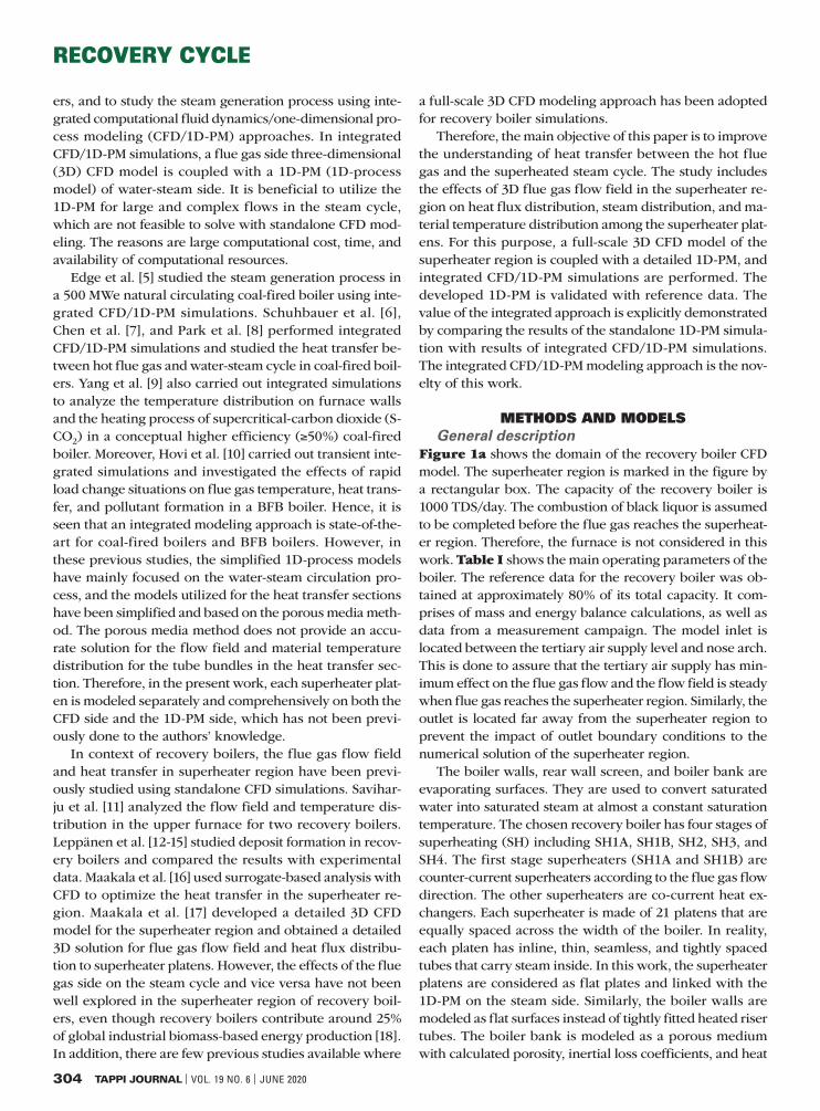
The consistency and accuracy of the developed 1D-PM are analyzed by comparing its results with reference data. This is done before performing the integrated CFD/1D-PM sim-ulations. The boundary conditions for the 1D-PM are shown in Table III and Table IV, which are based on reference data. The thermal wall boundary conditions of the super-heater platens are given as a uniform heat flux distribution, which is a common approach when no more detailed in-
formation is available. The computed results of 1D-PM are in good agreement
with reference data, as is shown in Table V. The calculated pressure losses (ΔP1D-PM) and steam superheating (ΔT1D-PM) across the superheaters deviate from reference data by a maximum of 9% and 3%, respectively. The main steam mass flow rate calculated by 1D-PM is similar to reference data. However, the main steam pressure and temperature deviate by 1.4% and 1%, respectively. The main reasons for the previously mentioned discrepancies are pipe friction and form losses due to the complex geometry of connect-ing pipes, headers, steam flow loops in the superheater platens, and the main steam pipe. Therefore, based on this validation study, the developed 1D-PM is considered to be consistent with good accuracy.
Integrated CFD/1D-PM simulationsFlue gas sideFigure 5a shows the flue gas flow field in the middle of the superheater region. Three recirculation zones (1, 2, and 3) are identified; these kinds of vortex structures at differ-ent locations are also noted in other recovery boiler simula-tions such as Saviharju et al. [11] and Maakala et al. [16,17]. The smaller recirculation zones 2 and 3 are located in the corner of the front cavity and below the SH4 platens, respec-tively. The larger recirculation zone (LRZ) (1) is located in the middle of the superheater region, and it extends mainly from SH2 platens to SH4 platens across the boiler width and depth. The observations indicate that the partial boiler load (80%) and uneven inlet velocity profile are responsible for the occurrence of these vortex structures. Engblom et al.
Superheatersqtotal ,
kWPlatens
qplaten ,
kW
q”platen ,
kW/m2
SH1A 3814 21 181.62 4.75
SH1B 3566 21 169.81 5.71
SH2 9773 21 465.38 9.89
SH3 8209 21 390.90 7.72
SH4 3017 21 143.67 3.75
IV. Heat flux distribution to superheater platens based on reference data.
Pressure Losses and Steam Superheating for Superheaters
SuperheatersΔPref , bar
ΔTref , °C
ΔP1D-PM , bar
ΔT1D-PM, °C
SH1A 0.41 14 0.43 13.7
SH1B 0.35 18 0.38 18.1
SH2 2.20 69 2.28 68.1
SH3 2.04 73 2.14 71.8
SH4 2.60 28 2.77 27.2
Main Steam Properties
Parameters Reference Data 1D-PM Error, %
P, bar 111.9 110.29 1.4
T, °C 506 501.3 1.0
ṁ, kg/s 38.2 38.2 -
V. Comparison between reference data and developed 1D-PM for validation study. The table shows that complex geometry of the superheated steam cycle is mainly responsible for deviations in pressure losses, steam superheating, and main steam properties.

RECOVERY CYCLE
310 TAPPI JOURNAL | VOL. 19 NO. 6 | JUNE 2020
[24] also noted the effect of partial furnace load on asym-metries in the flow field in a recovery boiler using both measurements and CFD simulations.
Figure 5b shows the flue gas temperature field in the middle of superheater region. The vortex structures, espe-cially LRZ, significantly affect the flue gas temperature field. The flue gas temperature in LRZ is in the range of 440°C–530°C, which is lower than the surrounding flue gas temperature. The surface areas of superheater platens in this zone, therefore, are inefficiently used for heat trans-fer. Hence, the uneven flow field in superheater region is connected to variations in platen-wise generated steam properties and material temperature distribution, which are analyzed in the “Steam side” section of this paper.
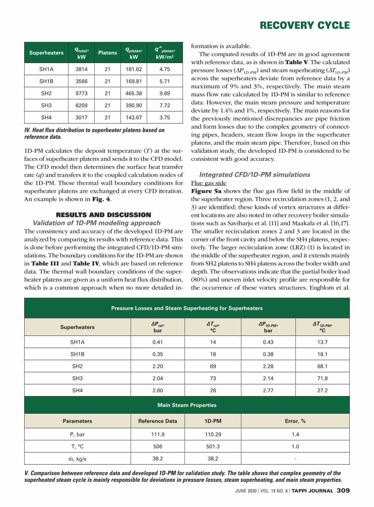
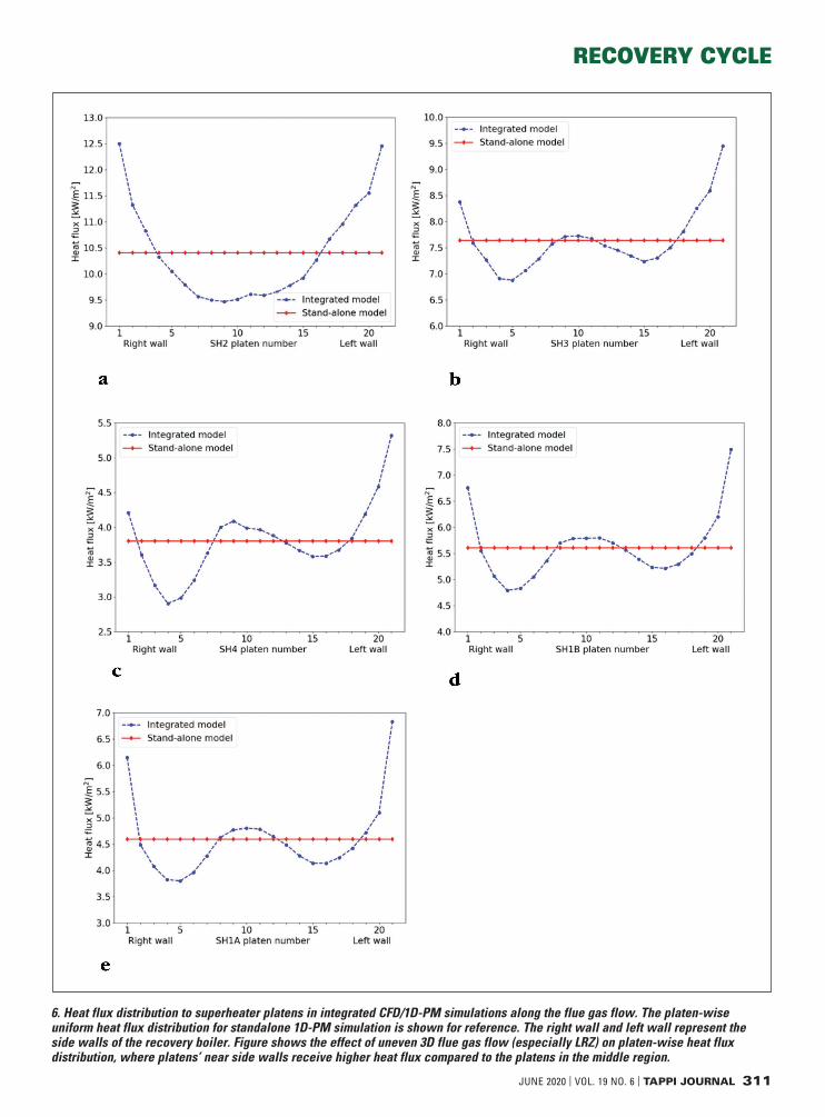
The heat flux distribution to the superheater platens in integrated CFD/1D-PM simulations is shown in Fig. 6. In the figure, the uniform platen-wise heat flux distribution for the standalone 1D-PM simulation is also shown for ref-erence, because a uniform distribution is a common as-sumption when CFD simulation data or other detailed in-formation is not available.
The 3D flow field in the superheater region substan-tially affects the platen-wise heat flux distribution for su-perheaters. The LRZ in the middle of superheater region leads to lower heat flux on the middle platens compared to platens near side walls, as shown in Fig. 6. The largest dif-ferences for platen-wise heat flux distribution are noted for SH4 and SH1A, where the heat fluxes on the platens near side walls are, respectively, 83% and 80% higher than the platens in the middle region.
Steam sideThe steam side results for integrated CFD/1D-PM simula-tions and their comparison with a standalone 1D-PM simu-lation are discussed in this section. The comparison study is performed to explicitly show the effect and advantages of an integrated modeling approach over a standalone 1D-PM simulation. For the purpose of this comparison, the total heat transfer to each superheater in the standalone 1D-PM simulation was set to be the same as in integrated CFD/1D-PM simulations. In this paper, for brevity, the com-parison results for SH1A and SH4 are mainly discussed.
The main steam values including pressure, temperature, and mass flow rates in integrated simulations and the stand-alone 1D-PM simulation are close to each other, with neg-ligible deviations. For both simulations, these values are approximately 110.2 bar, 504°C, and 38.2 kg/s. Figure 7 shows the total outlet steam mass flow rate from each su-perheater. For both integrated CFD/1D-PM and standalone 1D-PM simulations, the geometrical structure of the main steam pipe causes a variation in outlet steam mass flow rates for the SH4 outlet header.
The platen-wise pressure losses, steam distribution, and steam temperature for SH1A and SH4 are shown in Fig. 8. The pressure losses calculated in integrated CFD/1D-PM and standalone 1D-PM simulations are close to each other, with small discrepancies. For both simulations, the maxi-mum differences of 2.4% and 0.8% in platen-wise pressure losses are found for SH1A and SH4, respectively. The de-viations in pressure losses for SH1B, SH2, and SH3 are 6%, 1.86%, and 1.5%, respectively.
5. (a) The solved velocity field for flue gas. Figure shows the larger recirculation zone (LRZ) in the middle of the superheater region (1) with two minor zones (2-3). These are mainly formed due to partial boiler load and non-uniform inlet boundary conditions. (b) The solved flue gas temperature field. Figures are taken from the middle of the boiler width.
RECOVERY CYCLE
JUNE 2020 | VOL. 19 NO. 6 | TAPPI JOURNAL 311
6. Heat flux distribution to superheater platens in integrated CFD/1D-PM simulations along the flue gas flow. The platen-wise uniform heat flux distribution for standalone 1D-PM simulation is shown for reference. The right wall and left wall represent the side walls of the recovery boiler. Figure shows the effect of uneven 3D flue gas flow (especially LRZ) on platen-wise heat flux distribution, where platens’ near side walls receive higher heat flux compared to the platens in the middle region.

RECOVERY CYCLE
312 TAPPI JOURNAL | VOL. 19 NO. 6 | JUNE 2020
Moreover, the 3D heat flux distribution in the super-heater region has a smaller impact on platen-wise steam distribution compared to the pressure losses caused by the complex geometry of the superheated steam cycle. The comparison study shows that maximum differences be-tween platen-wise steam distribution for SH1A and SH4 are 2.3% and 0.56%, whereas they are 2.3%, 2.2%, and 1.09% for SH1B, SH2, and SH3, respectively. For integrated CFD/1D-PM simulations, the deviations between minimum and maximum platen-wise steam mass flow rates are in the range of 3%–7%.
However, the non-uniform 3D heat flux distribution in the superheater region has a substantial effect on platen-wise generated steam temperatures. For SH1A and SH4, the platens near the side walls have higher steam temperatures compared to platens in the middle region, as these platens receive higher heat fluxes (Fig. 8). Similar behavior is also observed for other superheaters. For integrated CFD/1D-PM simulations, the deviations in platen-wise superheating are in the range of 45%–122% for all the superheaters. On the contrary, the standalone 1D-PM simulation provides almost uniform platen-wise steam temperatures for the superheat-ers. Therefore, it is considered that the superheated steam generation process based on the uniform heat flux distribu-tion approach is not an accurate method, as it does not con-sider the effects of the flow field in the superheater region.
The platen-wise material temperature distribution for outer (shortest) and innermost (longest) steam flow loops in SH1A and SH4 are shown in Fig. 9. Similar to platen-wise steam temperature distribution, the standalone 1D-PM simulation provides almost uniform and most like-ly inaccurate results. It is considered that in reality the non-uniform platen-wise heat flux distribution in the su-
perheater region should be accountable for variation in the flow loop-wise material temperature distribution. In fact, the integrated CFD/1D-PM simulations are able to capture these complex phenomena, as is shown in Fig. 9. More-over, the results of integrated CFD/1D-PM simulations are also compared with measurement data, which show simi-lar trends in material temperatures. The deviations are in the range of 1%–6% (Table VI). For all the superheaters, the average differences between measurements and results of integrated CFD/1D-PM simulations are between 0.7%–2.6% (Table VI). The variation in the flow field in the su-perheater region during measurements and integrated CFD/1D-PM simulations is considered to be primarily re-sponsible for these discrepancies.
CONCLUSIONSThe developed integrated CFD/1D-PM modeling ap-proach was demonstrated to be feasible for solving the complex heat transfer phenomena between steam and flue gas in the superheater region with good accuracy. In comparison to previous approaches (porous media meth-od [5-10] and 3D slice superheater region method [11-16]), the relevant flow and heat transfer phenomena are cap-tured on a much more detailed level. The integrated mod-eling approach explicitly explains that the uneven flue gas flow in the superheater region is closely linked with significant variations in platen-wise steam superheating temperature (45%–122%) and superheater material tem-perature distribution (1%–6%).
The identified larger recirculation zone (LRZ) suggests further study on creating recovery boiler designs that min-imize the size and effect of such recirculation zones. How-ever, it is also noted that in fully time-dependent simula-tions, the effect of the LRZ would possibly be smaller than in the present simulations, because the size and location of the recirculation zone would most likely move, tending to mitigate some of the impact on the heat transfer rates on a platen-by-platen basis. This further highlights the impor-
SuperheatersAverage
Difference, %
Maximum Difference,
%
Location for Maximum Difference, platen-loop
SH1A 0.7 1.6 7-3
SH1B 1.0 2.5 7-1
SH2 1.5 3.2 5-3
SH3 2.2 5.7 10-3
SH4 2.6 5.0 10-3
VI. Average and maximum differences between measurement data and results of integrated CFD/1D-PM simulations for superheater material temperature distribution.
7. The outlet steam mass flow rates from the exits, including right wall side (RW) and left wall side (LW) of outlet headers, for all the superheaters. For both integrated and standalone simulations, the variation in mass flow rates for the SH4 outlet header is mainly caused by geometry of the main steam pipe and associated friction and form losses.

RECOVERY CYCLE
JUNE 2020 | VOL. 19 NO. 6 | TAPPI JOURNAL 313
8. Platen-wise pressure losses, mass flow rates and steam temperature for SH1A (a, b, and c) and SH4 (d, e, and f). Figure shows that the geometrical structure of the superheated steam cycle has significant effects on platen-wise pressure losses and steam mass flow rates. The integrated simulations reveal that variations in platen-wise steam superheating are closely associated with uneven flue gas flow in the superheater region.

RECOVERY CYCLE
314 TAPPI JOURNAL | VOL. 19 NO. 6 | JUNE 2020
tance of future work regarding fully time-dependent cou-pled simulations.
The integrated CFD/1D-PM modeling approach pro-vides a novel way to understand the heat transfer and su-perheating process in a comprehensive and more realistic manner. It could be a useful tool for troubleshooting su-perheaters and selecting their design margin for the future, as well as for performance optimization, including reduc-tion in material issues and higher quality superheated steam production. Therefore, it would be a relevant ap-proach to improve the safety, energy efficiency, and cost efficiency of a recovery boiler. Moreover, this integrated modeling approach could also be relevant to other energy
production applications, such as biomass-fired boilers and utility boilers.
Based on the results, the following future research di-rections are identified:
1. Full-scale time-dependent integrated CFD/1D-PM simulations, including black liquor combustion in the lower furnace, will be performed to further investi-gate the superheated steam generation process in a more precise way. This full-scale integrated modeling also corresponds more accurately to real recovery boiler operation. With this approach, rapid load change situations can also be studied.
2. For inlet and outlet headers, a CFD study will be per-
9. Platen-wise material temperature distribution of SH1A (a and b) and SH4 (c and d). The outermost (shortest) flow loop is represented as L1, whereas L3 (SH4) and L4 (SH1A) represent the innermost (longest) flow loops. Figure indicates variations in material temperature distribution both in the integrated simulations (considered to be caused by non-uniformities in the flow field) and in the measured data (considered to arise from real recovery boiler operation).

RECOVERY CYCLE
JUNE 2020 | VOL. 19 NO. 6 | TAPPI JOURNAL 315
formed to precisely understand the effects of their geometries on steam distribution. It will help to ex-plore new possibilities for optimizing their perfor-mance and design.
3. We are planning to study how the thicknesses of de-posits affect the results of a coupled CFD/1D-PM model when moving from a clean boiler state (after startup) to a more fouled boiler state (after long con-tinuous operation). TJ
LITERATURE CITED1. Official Statistics of Finland (OSF), “Production of electricity and
heat,” Helsinki, ISSN=1798-5099. Available [Online] http://www.stat.fi/til/salatuo/index_en.html <8June2020>.
2. Pöyry, “World fibre outlook up to 2030,” Pöyry Oyj, Helsinki, 2016.
3. Tran, H. and Vakkilainen, E., Int. Colloq. Eucalyptus Pulp, 3rd, ABTCP, São Paulo, Brazil, 2007, p. 4.
4. Salmenoja, K., 55th Anniv. Int. Recovery Boiler Conf., Finnish Recovery Boiler Committee, Vantaa, Finland, 2019, p. 175.
5. Edge, P.J., Heggs, P.J., Pourkashanian, M., et al., Comput. Chem. Eng. 35(12): 2618(2011). https://doi.org/10.1016/j.compchemeng.2011.04.003.
6. Schuhbauer, C., Angerer, M., Spliethoff, H., et al., Fuel 122: 149(2014). https://doi.org/10.1016/j.fuel.2014.01.032.
7. Chen, T., Zhang, Y.J., Liao, M.R., et al., Fuel 240: 49(2019). https://doi.org/10.1016/j.fuel.2018.11.008.
8. Park, H.Y., Faulkner, M., Turrell, M.D., et al., Fuel 89(8): 2001(2010). https://doi.org/10.1016/j.fuel.2010.01.036.
9. Yang, Y., Bai, W., Wang, Y., et al., Appl. Therm. Eng. 113: 259(2017). https://doi.org/10.1016/j.applthermaleng.2016.11.043.
10. Hovi, V., Huttunen, M., Karppinen, I., et al., Energy Procedia 120: 508 (2017). https://doi.org/10.1016/j.egypro.2017.07.186.
11. Saviharju, K., Pakarinen, L., Wag, K., et al., Int. Chem. Recovery Boiler Conf., TAPPI PRESS, Atlanta, GA, USA, 2004, p. 247.
ABOUT THE AUTHORSThe main purpose of this work is to improve the understanding about heat transfer between the hot flue gas and the superheated steam cycle by considering the effects of 3D flow field, tempera-ture distribution, and circulating steam properties. The previous studies were based on either simpli-fied standalone CFD simulations or simplified inte-grated CFD/1D-PM modeling approach. In this present work, each superheater platen is modeled separately and comprehensively on both the CFD side and the 1D-PM side, which is the novelty of this work.
The most challenging part of this research was to develop both of the computational models as pre-cisely as possible. This was achieved by cautiously selecting the cell sizing and number of calculation nodes for the CFD model and the 1D-PM model, re-spectively. The accurate discretization is important for connecting both computational models and effi-ciently performing integrated CFD/1D-PM simulations.
In comparison to previous studies, the present in-tegrated CFD/1D-PM modeling approach solved the 3D flue gas flow field and heat transfer phenomena in the superheater region in a comprehensive and more realistic way. The study explicitly shows that the uneven flue gas flow in the superheater region is closely linked with significant variations in steam superheating temperature and superheater material temperature distribution. Moreover, it is also found that commonly utilized uniform heat flux approach for the superheating process is not accurate, as it does not consider the effect of flue gas flow field in the superheater region.
This modeling approach could be a useful tool
for troubleshooting superheaters and optimizing their performance. It could also be utilized to study rapid load change situations in recovery boilers. Therefore, it would be a relevant method to improve safety, energy efficiency, and cost efficiency of a re-covery boiler and the pulp mill in totality.
As a next step, a full-scale time-dependent inte-grated CFD/1D-PM simulation, including black liquor combustion in the lower furnace, will be performed to further investigate the superheated steam gener-ation process in a more precise way. We are also planning to study how the thicknesses of deposits affect the results of the coupled CFD/1D-PM model when moving from a clean boiler state (after start-up) to a more fouled boiler state (after long continu-ous operation).
Kumar is development engineer and Maakala is development engineer with Andritz Oy in Helsinki, Finland. Vuorinen is assitant professor of Fluid Physics in the Department of Mechanical Engineering at Aalto University, Espoo, Finland. Email Kumar at [email protected].
MaakalaKumar Vuorinen

RECOVERY CYCLE
316 TAPPI JOURNAL | VOL. 19 NO. 6 | JUNE 2020
12. Leppänen, A., Välimäki, E., Oksanen, A., et al., TAPPI J. 12(3): 25(2013). https://doi.org/10.32964/TJ12.3.25.
13. Leppänen, A., Tran, H., Taipale, R., et al., Fuel 129: 45(2014). https://doi.org/10.1016/j.fuel.2014.03.046.
14. Leppänen, A., Tran, H., Välimäki, E., et al., J. Sci. Technol. For. Prod. Processes 4(1): 50(2014).
15. Leppänen, A. and Välimäki, E., TAPPI J. 15(3): 187(2016). https://doi.org/10.32964/TJ15.3.187.
16. Maakala, V., Järvinen, M., and Vuorinen, V., Energy 160: 361(2018). https://doi.org/10.1016/j.energy.2018.07.002.
17. Maakala, V., Järvinen, M., and Vuorinen, V., Appl. Therm. Eng. 139: 222(2018). https://doi.org/10.1016/j.applthermaleng.2018.04.084.
18. Vakkilainen, E., Kuparinen, K., and Heinimö, J., “Large industrial users of energy biomass,” IEA Bioenergy Task 40, 2013.
19. Wessel, R.A., Denison, M.K., and Samretvanich, A., TAPPI J. 83(7): 1(2000).
20. Li, B., Brink, A., and Hupa, M., Fuel Process. Technol. 105:149(2013). https://doi.org/10.1016/j.fuproc.2011.08.007.
21. Zbogar, A., Frandsen, F.J., Jensen, P.A., et al., Prog. Energy Combust. Sci. 31(5-6): 371(2005). https://doi.org/10.1016/j.pecs.2005.08.002.
22. Alobaid, F., Mertens, N., Starkloff, R., et al., Prog. Energy Combust. Sci. 59: 79(2017). https://doi.org/10.1016/j.pecs.2016.11.001.
23. Faculty of Engineering and Applied Science, Mechanical and Materials Engineering, Queen’s University, “Losses in pipes,” Kingston, ON, Canada. Available [Online] https://me.queensu.ca/People/Sellens/LossesinPipes.html <6June2020>.
24. Engblom, M., Miikkulainen, P., Brink, A., et al., TAPPI J. 11(11): 19(2012). https://doi.org/10.32964/TJ11.11.19.
ABOUT THIS PAPER
Cite this article as: Kumar, K., Maakala, V., and Vuorinen, V., TAPPI J. 19(6): 303(2020). https://doi.org/10.32964/TJ19.6.303
DOI: https://doi.org/10.32964/TJ19.6.303
ISSN: 0734-1415
Publisher: TAPPI Press
Copyright: ©TAPPI Press 2020
About this journal
Custom doctor solutions. For better paper.Essco’s best-in-class doctor blades, doctoring systems and maintenance
programs help some of the world’s largest and fastest paper machines deliver
consistent, trouble-free performance. Which means increased production,
higher quality and greater profitability. That’s the Essco difference.
PH: 920.494.3480800.835.7134
email: [email protected]
Essco-Paper360-Ad-2019-7x4_583-vF.indd 1 1/10/19 11:15 AM953576_ESSCO.indd 1 2/19/19 11:20 PM