integrated solution for an instrument panel - krauss-maffei · injection molding the next stop is...
TRANSCRIPT

23
I N J E C T I ON MOLD ING
>
Kunststoffe international 6/2010
MARKUS BETSCHE
We were looking for a supplier whocould cover the maximum pos-sible number of manufacturing
steps for the instrument panel of the newAudi, because of its high complexity andthe interdependence of the individualsteps,” is how Anton Simon, plant man-ager of Peguform, an automotive 1-Tier-supplier in Neustadt, Germany, sums upthe background to what in many ways isa special project. Ultimately, the compa-ny chose to partner with KraussMaffei
Technologies GmbH, Munich, Germany,which now deploys its own solutions tocover a range of manufacturing steps,from injection molding via polyurethaneprocessing through to automation. Butthat’s not all.
Changing on the Fly
In the difficult changeover phase, whenPeguform had to seamlessly switch fromproducing the previous Audi A4 model(internal designation: B7) to the currentmodel (B8), KraussMaffei provided amodern foaming installation on loan tohelp Peguform cope with the first proto-types of the new A4. Torben Englisch,head of industrial engineering at Pegu-
form, describes just how quickly thechangeover occurred: “Production com-menced in week 36 of 2007, and then gotinto full swing from week 50 on. The B7used to be produced on the old rotarytable, while the B8 was made on the up-right installation. We dismantled the oldfoamer/rotary table over Christmas andinstalled the new one, including flame-treatment unit, removal robots, and wetcell, and had it ready for operation in ear-ly 2008. It was then used to make the B8,while the upright installation producedthe B7.” Over time, production numberswere reversed: the B8 was ramped up, andthe B7 ramped down.
Peguform now produces 1,800 instru-ment panels a day, plus 7,000 bumper sys-
Integrated Solution for anInstrument PanelProcess Chain. Production of the instrument panel of the new Audi A4 necessitat-
ed combining numerous processing techniques into a highly complex production
line. A concatenation of injection molding machine, rotary table foam installation
and several assembly robots makes for a smooth process flow.
Production of theinstrument panel forthe new Audi A4combines a wealth ofprocessing, assemblyand safety tech-niques (photo: Audi)
Translated from Kunststoffe 6/2010, pp. 42–45Article as PDF-File at www.kunststoffe-international.com; Document Number: PE110422
23-26_PE110422_PE6 10.06.2010 9:18 Uhr Seite 23

24
I N J EC T I ON MOLD ING
© Carl Hanser Verlag, Munich Kunststoffe international 6/2010
tems, 8,000 door panels and 7,000 rock-er panels – every day. In general, produc-tion is back to normal levels. “We haveweathered the crisis. We were back to op-erating at full capacity in May 2009 andhave now abandoned short-time work-ing,” says plant manager Simon.
Prime Example of a ComplexProcess Chain
The production line for the instrumentpanel, a prime example of a complexprocess chain, comprises a large numberof coordinated individual steps, such asinjection molding, flame treatment,foaming, cutting, milling and automa-tion. “The Audi A4 instrument panelcomes in two versions, namely left- andright-hand drive. In addition, there arethree colors each. This yields a total of sixvariants,” says Englisch, before adding“Of course, there are a lot more left-hand-drive brackets to be made.” All thebrackets are molded from continuous-strand reinforced polypropylene on MC2300-19000 KraussMaffei machines. Theentire mechanism for holding the airbagmodule and the air flow system requiredfor protecting the airbag are integratedinto the part by the injection moldingstage.
When a molded bracket is removed, acamera system performs a 100 % visualsafety inspection on it. It is then bufferedfor two hours on a conveyor line, where-upon a robot takes it and centers it forthe next processing step – flame treat-ment.
The flame-treatment unit pivots intothe processing station, and the three-sta-tion rotary table rotates further and therobot traverses a defined area. Flametreatment is essential for ensuring that thePU will adhere. However, adhesion is un-desirable in some areas and so they aremasked with stencils which have been de-
signed to fit the contours. Torben En-glisch explains:“Masking’s important forensuring that whatever is cut out andmilled later can be easily removed, that is,foam-free and flash-free.”
The flame treatment complete, the ro-tary table rotates further to the removalstation. Waiting there is a handling robotthat receives both the flame-treated partand later lifts the finished part from thefoaming mold. Between these two steps,the KraussMaffei-built rotary table/foam-ing installation moves into the loadingposition.
Foaming on a Six-stationRotary Table
In a parallel rotary sintering process, PVCpowder is sintered to form a slush-mold-ed skin. The skin is fed to the rotarytable/foaming installation by conveyor.Atthe operating stations of the rotary table,the skin is manually inserted into the low-er half of the mold (Fig. 1). Before that, thegripper picks up the molded bracket ful-ly automatically by the upper ram (Fig. 2).For foam application, the entire mold car-rier pivots into a 30° oblique foaming po-sition. “This affords the best foam distri-bution and venting,” says the head of in-dustrial engineering.
Then, before foaming begins, the car-rier moves into the safety zone, where theairbag area of the slush-molded skin isblow-dried again to seal the already pre-
KraussMaffei Technologies GmbHD-80997 MunichGermanyTEL + 49 89 8899-0> www.kraussmaffei.com
Contacti
Fig. 1. An operatorplaces the slushmolded skin by handinto mold carrier (photos 1–6: KraussMaffei)
Fig. 2. The rotary table foaming installation; at the front, a mold carrier in mounting position with in-serted instrument panel bracket. For foaming, the entire mold carrier pivots into a 30° oblique position
23-26_PE110422_PE6 10.06.2010 9:18 Uhr Seite 24
25
I N J E C T I ON MOLD ING
>
Kunststoffe international 6/2010
pared breaking point and keep out thepolyurethane foam. Foaming com-mences on a six-station rotary table fit-ted with six electrical mold carriers ca-pable of producing any combination ofleft- and right-hand-drive versions.When the reaction time has elapsed, themold carrier opens in the removal posi-tion.
The robot fetches a new instrumentpanel bracket from the flame-treatmentunit and places it on the upper ram, andthe ejectors on the lower mold part areextended to allow the gripper to removethe finished part and place it on a convey-or belt with appropriately shaped recep-tacles. An employee then checks the sur-
face of every finished, foamed part. It issubsequently manually fed to a Krauss-Maffei-supplied cutting center and auto-matically inserted into the cutting tool.This step features an integrated processbuffer in which the part cools and post-cures for 20 minutes.
A Cutting Tool Shaped Like aHedgehog
In the next step, the part is placed on thepresenting station of the cutting line. Thecutting line is slightly uncoupled from thedirect cycle sequence, that is, the opera-tor does not have to insert the part in sync.A robot picks up the part and puts it in-to the cutting tool. There follows a com-plex cutting process that accounts for85 % of total cutting. Says Englisch:“Thecutting tool has more than 22 slide toolsand looks a bit like a hedgehog. The indi-vidual blades make cuts in different di-rections.” A second removal robot re-moves the cut bracket and places it in the
holder of the milling cutter. Special atten-tion is given to safe removal of the waste:cutting tool and installation are opti-mized accordingly to guarantee trouble-free series production.
The instrument panel is then conveyedinto the sound-proofed milling cell viathe servo-driven horizontal rotary table,where two robots work as a kind of dou-ble milling cutter. They see to both theresidual cutting, which the punching unitcannot manage on account of the geom-etry,and weakening of the airbag support.The mills cut a perforation in the supportbehind the injected airbag panel that ful-ly penetrates the bracket and foam. Thisensures that the life-saving air bag canshoot out in a flash in the event of impact(car crash).
Safety First
The cell contains an automatic change-over station for the milling cutters, withthe tool length being measured after eachcycle.“The airbag is a safety-critical part.If the milling cutter is shorter than thecontrol expects, we assume a breakage hasoccurred,” explains the Peguform engi-neer. The defective bracket is then imme-diately changed and arrangements are au-tomatically made for it to be destroyed.“That way, we prevent a bracket with anysort of defective cut in the airbag areafrom being shipped to the customer,” hesays, describing the underlying safetythinking.
If the test instrument gives the greenlight, the mill holder is removed and thefinal machined part is presented to the re-moval robot, which places it on a convey-or belt. There, an operator removes theprojecting skin pieces. This manual re-moval of residual foam harbors the prob-lem that not only submersed cuts, but al-so oversize cuts are implemented – whichis why masking is performed at the startof the process: if these areas had beenflame-treated, the skin and foam wouldnot detach from the bracket.
Peguform GmbH processes 70 tons ofplastic pellets by means of injection mold-ing, foaming, laminating and coatingprocesses every day at its plant in Neustadt-Schwaig, Germany. These are supported bythe cutting methods of punching and cuttingas well as the joining methods of adhesivebonding and ultrasonic welding. Two just-in-sequence centers for Audi and BMW ensurereliable delivery to customers. A compe-tence center adjoining the plant serves tofurther develop the slush molding and foam-ing processes as well as various safetytechnologies.www.peguform.de
Company Profile!
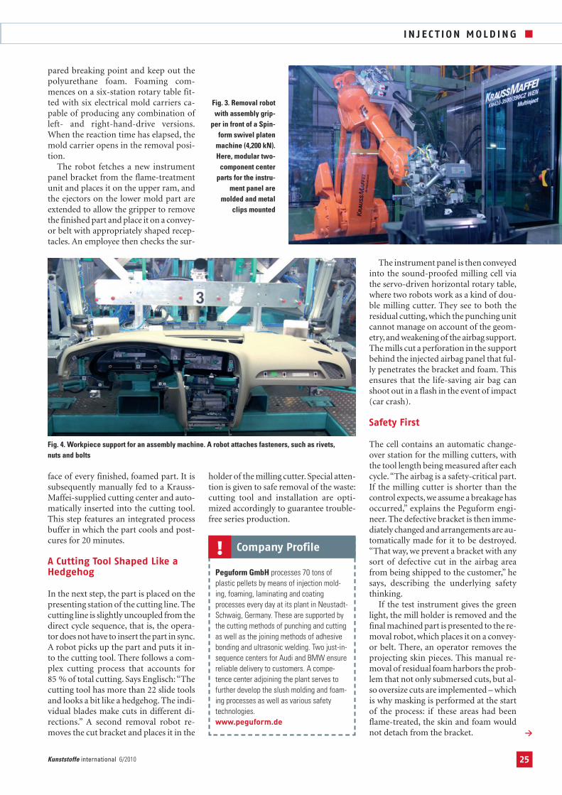
Fig. 3. Removal robotwith assembly grip-
per in front of a Spin-form swivel platen
machine (4,200 kN).Here, modular two-
component centerparts for the instru-
ment panel are molded and metal
clips mounted
Fig. 4. Workpiece support for an assembly machine. A robot attaches fasteners, such as rivets, nuts and bolts
23-26_PE110422_PE6 10.06.2010 9:18 Uhr Seite 25

I N J EC T I ON MOLD ING
The next stop is the welding station,where the foamed bracket and two otherinjection molded parts – air duct and cen-tral part (Fig. 3) – are joined together. Eachpart variant passes through this installa-tion. The front of the part is inserted in-to one of the six receptacles, and passesthrough four downstream welding sta-tions to the removal station. Dependingon which part arrives, defined feed unitsbearing sonotrodes extend forward.Welding is followed by automated re-moval. Again, the part is placed on a con-veyor belt, and then fetched by an em-ployee.
100 Percent Checks to the Very Last Step
The final process step involves two ma-chines for attaching the fasteners (Fig. 4).KraussMaffei automated much of thisline, too. The first machine attaches fivehollow rivets and eleven large and elevensmall snap nuts to the bracket. It consistsof two robots, each of which attaches dif-ferent fasteners. Parameters monitored
here include the torque and fit of the in-dividual fasteners.
Three clips, the frame of the center de-froster, and the two side air vents andloudspeaker receptacles are assembledmanually in the decorative trim area.They are then fastened in place with cut-ting nuts in the second machine (Fig. 5).This joining installation additionally at-taches nine hexagonal bolts and twelvecutting nuts to the bracket. Furthermore,the holder for the electronic ignition lockand the combination panel brackets are
bolted, as well as numerous gratings forthe defroster and the speaker panels.
Peguform produces the large parts, andsubcontracts the small parts, such as thedefroster. The fasteners must be moni-tored meticulously for a perfect fit in or-
der that the later modules may fit 100%– because the gap dimensions, which inthe auto industry are considered a hall-mark of quality, depend on it.
Finally, the combined panel bracketand instrument bracket are bolted togeth-er to form the complete instrument pan-el. Again, exact positioning is crucial sothat the whole composite fits properly inthe instrument panel and offers the oc-cupants the usual quality appearance. Forthis reason, a 100 % check is carried outagain. The instrument panel is now fin-
ished and is placed manually in the ship-ping container for transport to Audi.
Conclusion
Production of the instrument panel forthe new Audi A4 is a prime example of apartnership which pools the differentcompetencies of the parties. Thus,KraussMaffei looked after the plant andprocess technology (injection molding,PU reaction technology, automation) andprovided machines on loan during thetransitional switchover phase of the mod-els. Peguform, supported by its in-housecenter of competence (slush-moldedskin, foaming, vehicle safety, airbag de-velopment), contributed its expertise as asystems supplier and, through deliveringthe project on time, including start-up,transition and roll-out planning, onceagain proved its reliability as a systemspartner for the automotive industry.�
THE AUTHOR
DIPL.-ING. (FH) MARKUS BETSCHE, born in 1965,is Product/Marketing Manager at KraussMaffei Tech-nologies GmbH, Munich, Germany.
Fig. 5. The assembly machines for the instrument panel of the Audi A4 at Peguform. This is where, inter alia, the receptacle for the ignition lock and the composite panel bracket are bolted together
Fig. 6. The project managers worked closely together (from left to right): Torben Englisch (Peguform),Wolfgang Rössler, Michael Schulze (both KraussMaffei), Anton Simon (Peguform)
Technology Report Archive: Articles withhigh focus on practical ideas and with additional background information ontrend-setting technologies available atwww.kunststoffe-international.com/tr
Kunststoffe-international.com
© Carl Hanser Verlag, Munich Kunststoffe international 6/201026
23-26_PE110422_PE6 10.06.2010 9:18 Uhr Seite 26