integrated rail yard automation for control, safety, … · carwash. until early 2012, the yard was...
TRANSCRIPT

INTEGRATED RAIL YARD AUTOMATION FOR CONTROL, SAFETY, AND EFFICIENCY
PRINCIPAL AUTHOR Stuart C. Forth II – Systems Engineer, M.C. Dean Inc. 2951 V Street NE, Washington DC 20018 [email protected] 202-683-7299 CO-AUTHOR Matthew B. Ercolino – Sr. Applications Engineer, Frauscher Sensor Technology USA 300 Carnegie Center #320, Princeton NJ 08540 [email protected] 609-250-7029 NUMBER OF WORDS
1929
ABSTRACT
Many light rail and Metro operators find the usage of axle counters has modernized and automated their rail yards by eliminating tedious and time consuming manual systems. In light of this improvement, the Maryland Transit Administration (MTA) decided to upgrade their North Avenue Yard in Baltimore, Maryland. The key objectives were to improve efficiency of vehicle movements, eliminate switch trailing, provide operators positive switch and route feedback, and increase situational awareness throughout the yard.
These objectives were achieved using a programmable logic controller (PLC) for route processing, switching, and signal lighting, along with the axle counter Frauscher Advanced Counter i (FAdCi) for vehicle detection. The FAdCi provides a software interface to the PLC via Frauscher Safe Ethernet (FSE), an open and freely available protocol, which enhances the system above and beyond traditional track circuit vehicle detection. Implementation of these modern systems allows for centrally available system diagnostics, insight to the quantity of cars stored in the yard, efficiency in operator scheduling and vehicle movement, reduces risk of operator injury, eliminates switch machine damage, and provides continuous event and alarm logging.
INTRODUCTION
Maryland Transit Administration’s North Avenue Yard is a light rail vehicle storage and maintenance facility located in the city of Baltimore. With 24 switch machines connecting 13 tracks, it has the capacity to store 47 light rail vehicles. A maintenance shop sits atop four tracks, and a fifth track contains a carwash. Until early 2012, the Yard was an entirely manual and ‘dark’ operation; there were no signal houses, no vehicle detection, and only hand-thrown switch machines. Operators aligned each switch along their route themselves by getting out from their vehicles and moving the points to the desired position with the hand throw lever. The first significant operational upgrade arrived in 2012, when electric switch machines, wayside switch pushbutton stations, cable trough, and two signal houses were installed. With this advancement, operators still had to exit the vehicle and walk the entire route to set each switch, but the physical strain of manually moving each switch is eliminated. This is particularly helpful during inclement weather. While an improvement over the original yard configuration, movements were still time
© AREMA 2016® 1379
consuming. Vehicle detection was absent, and switch machines were being damaged by trailing movements with no data logging available to track these events. To further optimize Yard operations, MTA decided to add automatic end-to-end routing and vehicle detection in late 2013. For the purposes of this discussion, optimization, relates to gaining efficiencies on entrance and exit times to and from the yard, improving personnel safety, decreasing equipment damage, increasing situational awareness, and rapidly building trains.
One major decision the MTA made for the project was to specify an axle counter to detect vehicles rather than traditional track circuits. Since the widespread use of axle counters in Europe has demonstrated their reliability and safety compared to track circuits, this paper will not explore the similarities and differences between the two; there are other, more detailed analyses of the subject available (1, 2). In order to deliver the additional information and insight, MTA needed more than a simple ‘track occupied’ or ‘track free’ indication from the new system; axle counters provided the foundation.
APPROACH
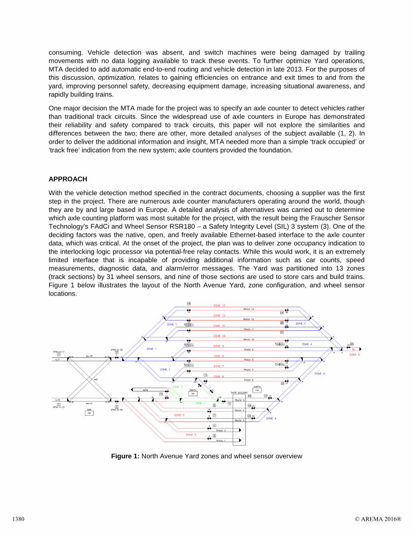
With the vehicle detection method specified in the contract documents, choosing a supplier was the first step in the project. There are numerous axle counter manufacturers operating around the world, though they are by and large based in Europe. A detailed analysis of alternatives was carried out to determine which axle counting platform was most suitable for the project, with the result being the Frauscher Sensor Technology’s FAdCi and Wheel Sensor RSR180 – a Safety Integrity Level (SIL) 3 system (3). One of the deciding factors was the native, open, and freely available Ethernet-based interface to the axle counter data, which was critical. At the onset of the project, the plan was to deliver zone occupancy indication to the interlocking logic processor via potential-free relay contacts. While this would work, it is an extremely limited interface that is incapable of providing additional information such as car counts, speed measurements, diagnostic data, and alarm/error messages. The Yard was partitioned into 13 zones (track sections) by 31 wheel sensors, and nine of those sections are used to store cars and build trains. Figure 1 below illustrates the layout of the North Avenue Yard, zone configuration, and wheel sensor locations.
Figure 1: North Avenue Yard zones and wheel sensor overview
1380 © AREMA 2016®
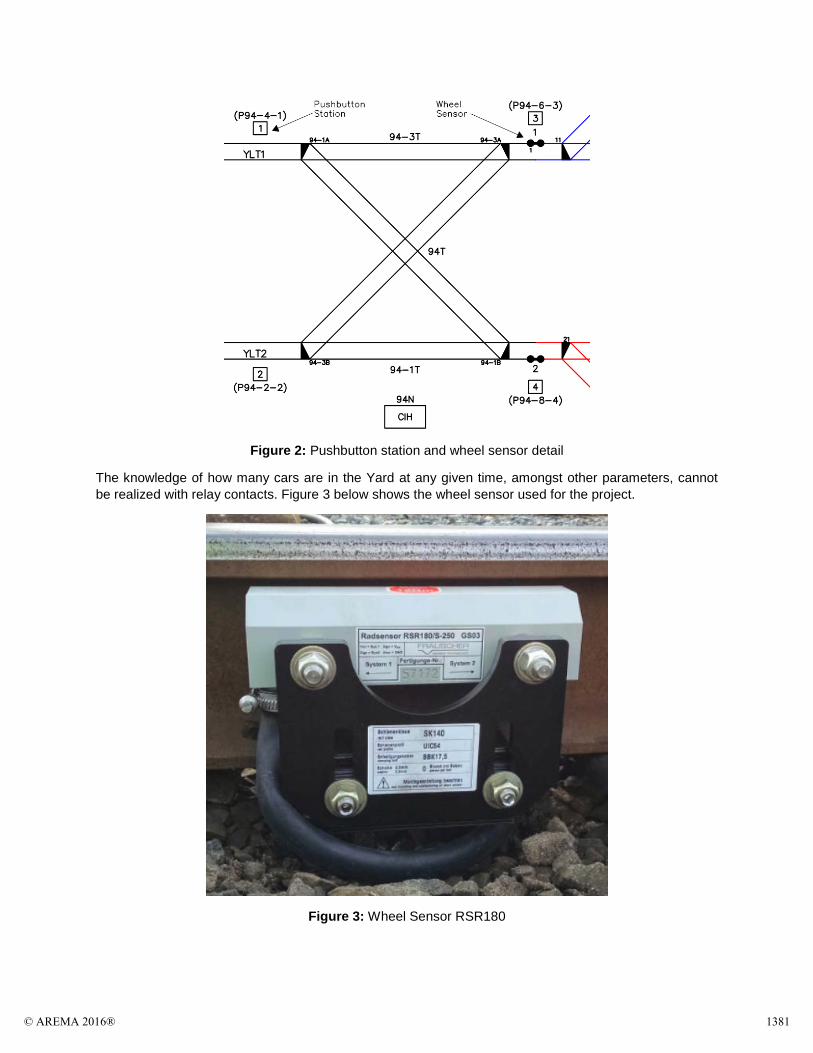
Figure 2: Pushbutton station and wheel sensor detail
The knowledge of how many cars are in the Yard at any given time, amongst other parameters, cannot be realized with relay contacts. Figure 3 below shows the wheel sensor used for the project.
Figure 3: Wheel Sensor RSR180
© AREMA 2016® 1381

Another important aspect of project delivery was selecting the PLC. The project called for redundant, hot-standby processors in the South signal house, and racks of input/output modules distributed in three signal houses. Much like for axle counters, there are also numerous PLC manufacturers to choose from. Ultimately the Schneider Electric Quantum platform was selected, as the MTA was familiar with the platform and interface options between existing MTA equipment.
The interface between the PLC and axle counter constituted a significant risk for the project. Frauscher Safe Ethernet (FSE) is a vital communications protocol which was designed specifically for the purpose of customer integration with other hardware, and was the ideal choice for the decentralized approach. FSE protocol documentation and message structure is well documented, but additional testing by M.C. Dean, Inc. was conducted prior to field installation to verify and validate. Generating FSE packets which were specific to this project and mirrored what the axle counter system hardware would produce, transmitting the packets to the PLC, and confirming the documentation matches what is observed before and during the selection phase of the axle counting equipment mitigated the largest risk to the project. Figure 4 shows the FSE simulator application connected to the PLC during systems integration testing.
Figure 4: FSE Simulator connected to PLC, with project-specific configuration
With the axle counting data being transmitted over an Ethernet network, the equipment was distributed between two signal houses. The native Ethernet networking functionality of the axle counter reduces the amount of copper cabling to each wheel sensor by moving the evaluator boards closer to the installation point. Since the axle counter has built-in communication capability, zone lengths are virtually limitless and detection points can be installed where needed, however remote the location may be, with only a data network needed to link the locations.
Situational awareness throughout the North Avenue Yard was delivered through the custom developed monitoring and control platform, provided by the system integrator – M.C. Dean, Inc. Figure 5 below shows an overview of the Yard that an administrator or maintenance staff member would interact with.
1382 © AREMA 2016®
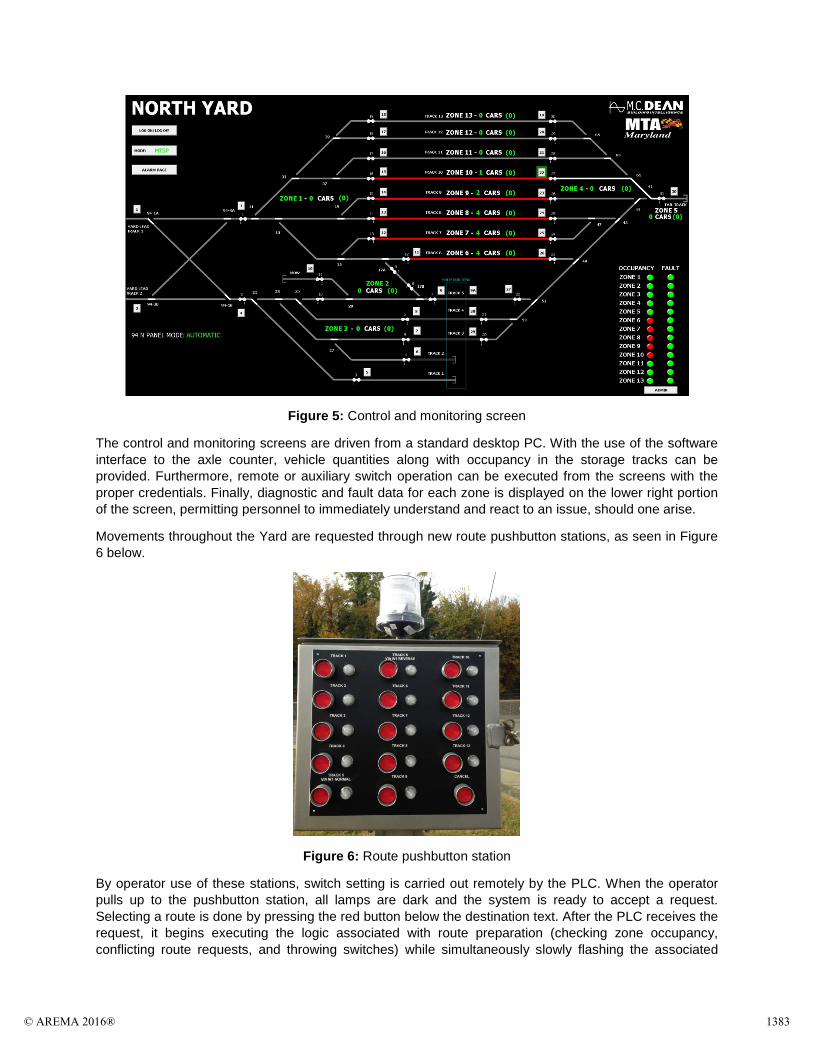
Figure 5: Control and monitoring screen
The control and monitoring screens are driven from a standard desktop PC. With the use of the software interface to the axle counter, vehicle quantities along with occupancy in the storage tracks can be provided. Furthermore, remote or auxiliary switch operation can be executed from the screens with the proper credentials. Finally, diagnostic and fault data for each zone is displayed on the lower right portion of the screen, permitting personnel to immediately understand and react to an issue, should one arise.
Movements throughout the Yard are requested through new route pushbutton stations, as seen in Figure 6 below.
Figure 6: Route pushbutton station
By operator use of these stations, switch setting is carried out remotely by the PLC. When the operator pulls up to the pushbutton station, all lamps are dark and the system is ready to accept a request. Selecting a route is done by pressing the red button below the destination text. After the PLC receives the request, it begins executing the logic associated with route preparation (checking zone occupancy, conflicting route requests, and throwing switches) while simultaneously slowly flashing the associated
© AREMA 2016® 1383
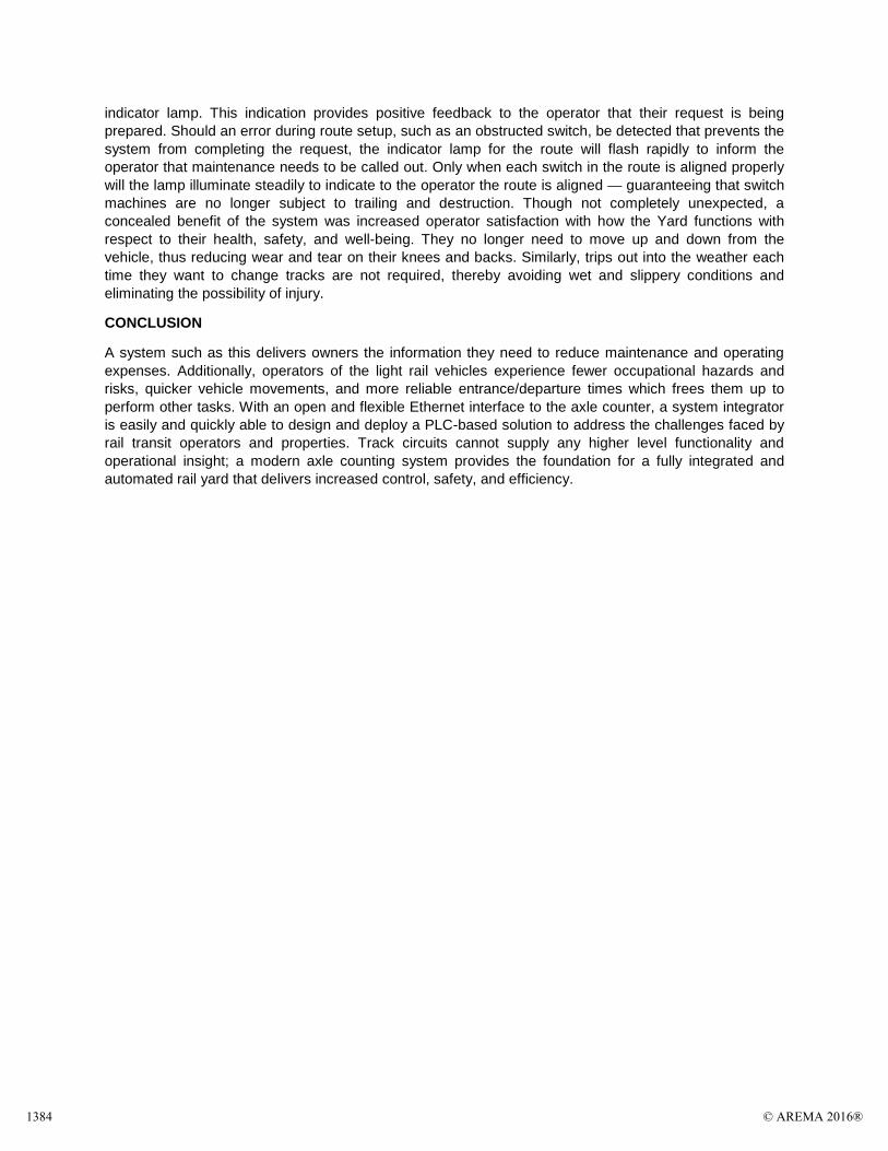
indicator lamp. This indication provides positive feedback to the operator that their request is being prepared. Should an error during route setup, such as an obstructed switch, be detected that prevents the system from completing the request, the indicator lamp for the route will flash rapidly to inform the operator that maintenance needs to be called out. Only when each switch in the route is aligned properly will the lamp illuminate steadily to indicate to the operator the route is aligned — guaranteeing that switch machines are no longer subject to trailing and destruction. Though not completely unexpected, a concealed benefit of the system was increased operator satisfaction with how the Yard functions with respect to their health, safety, and well-being. They no longer need to move up and down from the vehicle, thus reducing wear and tear on their knees and backs. Similarly, trips out into the weather each time they want to change tracks are not required, thereby avoiding wet and slippery conditions and eliminating the possibility of injury.
CONCLUSION
A system such as this delivers owners the information they need to reduce maintenance and operating expenses. Additionally, operators of the light rail vehicles experience fewer occupational hazards and risks, quicker vehicle movements, and more reliable entrance/departure times which frees them up to perform other tasks. With an open and flexible Ethernet interface to the axle counter, a system integrator is easily and quickly able to design and deploy a PLC-based solution to address the challenges faced by rail transit operators and properties. Track circuits cannot supply any higher level functionality and operational insight; a modern axle counting system provides the foundation for a fully integrated and automated rail yard that delivers increased control, safety, and efficiency.
1384 © AREMA 2016®

REFERENCES
(1) Blake A. Kozol, David F. Thurston, “Axle Counters vs. Track Circuits - Safety in Track Vacancy Detection and Broken Rail Detection.” American Railway Engineering and Maintenance-of-Way Association, August 2010, http://www.arema.org.
(2) Gerhard Grundnig, Christian Pucher, “Wheel Detection and axle counting system solutions for public transport systems”, Signal + Draht (103), 7+8/2012, p. 30-36, http://www.frauscher.com/en/media/#type=fachartikel
(3) SIL is defined in IEC 61508 for Electrical/Electronic programmable electronic safety related systems and in EN 50129:2003 for railway applications.
LIST OF FIGURES Figure 1: North Avenue Yard zones and wheel sensor overview Figure 2: Pushbutton station and wheel sensor detail Figure 3: Wheel Sensor RSR180 Figure 4: FSE Simulator connected to PLC, with project-specific configuration Figure 5: Control and monitoring screen Figure 6: Route pushbutton station
Stuart C. Forth II
Stuart is a Systems Engineer at M.C. Dean, Inc. in Washington DC. He has been with the firm for the past seven years, working on light and urban railway transit projects in the Washington DC metropolitan region. Stuart earned his B.S. from Michigan Technological University and his M.S. in Systems Engineering from Johns Hopkins University. He calls Alexandria, Virginia, home.
Matthew B. Ercolino
Matthew Ercolino is Senior Applications Engineer at Frauscher Sensor Technology USA, in Princeton, NJ. Matthew received his B.S. from Drexel University in Philadelphia and has worked in the rail industry for Amtrak as Principal Engineer for High Speed Rail Mechanical, Bombardier Transportation as a testing and commissioning supervisor for NYC and NEC projects and for Both Parsons and LTK Engineering Services as an electrical Engineer and Project Consultant. Matthew is based in the Philadelphia metropolitan area.
© AREMA 2016® 1385