integrated programming support system for micrex … · integrated programming support system for...
TRANSCRIPT
Integrated Programming Support System for MICREX-SX Series 25
Mitsunori FukuzumiMasashi YamadaAkihide Hamada
Integrated Programming Support Systemfor MICREX-SX Series
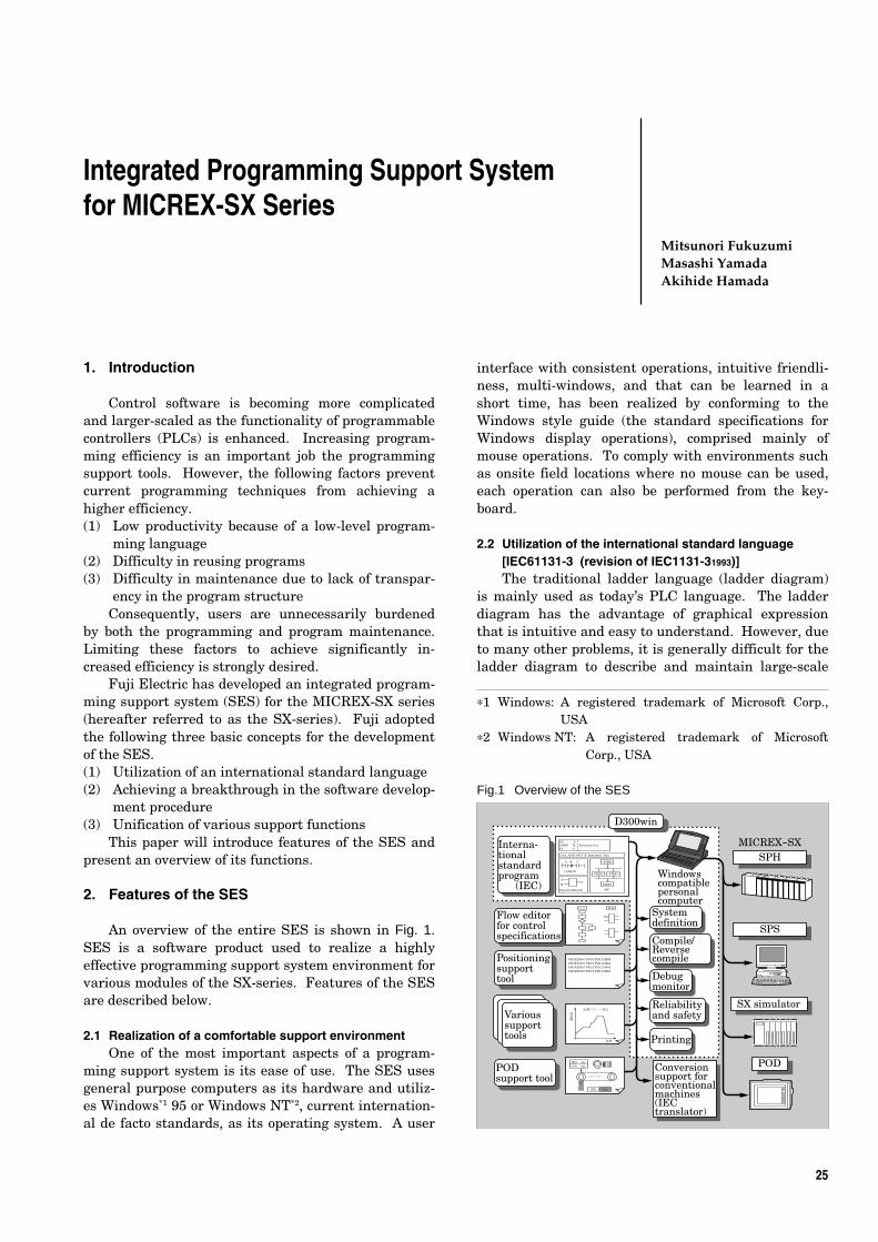
Fig.1 Overview of the SES
1. Introduction
Control software is becoming more complicatedand larger-scaled as the functionality of programmablecontrollers (PLCs) is enhanced. Increasing program-ming efficiency is an important job the programmingsupport tools. However, the following factors preventcurrent programming techniques from achieving ahigher efficiency.(1) Low productivity because of a low-level program-
ming language(2) Difficulty in reusing programs(3) Difficulty in maintenance due to lack of transpar-
ency in the program structureConsequently, users are unnecessarily burdened
by both the programming and program maintenance.Limiting these factors to achieve significantly in-creased efficiency is strongly desired.
Fuji Electric has developed an integrated program-ming support system (SES) for the MICREX-SX series(hereafter referred to as the SX-series). Fuji adoptedthe following three basic concepts for the developmentof the SES.(1) Utilization of an international standard language(2) Achieving a breakthrough in the software develop-
ment procedure(3) Unification of various support functions
This paper will introduce features of the SES andpresent an overview of its functions.
2. Features of the SES
An overview of the entire SES is shown in Fig. 1.SES is a software product used to realize a highlyeffective programming support system environment forvarious modules of the SX-series. Features of the SESare described below.
2.1 Realization of a comfortable support environmentOne of the most important aspects of a program-
ming support system is its ease of use. The SES usesgeneral purpose computers as its hardware and utiliz-es Windows*1 95 or Windows NT*2, current internation-al de facto standards, as its operating system. A user
interface with consistent operations, intuitive friendli-ness, multi-windows, and that can be learned in ashort time, has been realized by conforming to theWindows style guide (the standard specifications forWindows display operations), comprised mainly ofmouse operations. To comply with environments suchas onsite field locations where no mouse can be used,each operation can also be performed from the key-board.
2.2 Utilization of the international standard language[IEC61131-3 (revision of IEC1131-31993)]The traditional ladder language (ladder diagram)
is mainly used as today’s PLC language. The ladderdiagram has the advantage of graphical expressionthat is intuitive and easy to understand. However, dueto many other problems, it is generally difficult for theladder diagram to describe and maintain large-scale
*1 Windows: A registered trademark of Microsoft Corp.,USA
*2 Windows NT: A registered trademark of MicrosoftCorp., USA
LD ANDN ST
C:=A AND NOT B Structured Text
A B C
A B
A
B
C
C
Function Block図
Ladder図
STEP1
STEP4
SFC
STEP2 STEP3
Instruction List
G01X100.0 Y50.0 F20.0 M40G03X150.5 Y40.5 F22.0 M41G01X200.5 Y62.3 F18.5 M42G01X100.0 Y50.0 F20.0 M43
・・・
温調パターン設定
時間
設定値
速度 100m/s回転 150rpm
コンベア
コーラ
運転 停止
フロー 部品
Interna-tionalstandardprogram (IEC)
Positioningsupporttool
Varioussupporttools
POD support tool
Flow editor for control specifications
Systemdefinition
Windowscompatible personal computer
Compile/Reverse compile
Debugmonitor
D300win
SX simulator
POD
Reliabilityand safety
Printing
Conversion support for conventionalmachines(IEC translator)
SPS
SPHMICREX-SX
Vol. 45 No. 1 FUJI ELECTRIC REVIEW26
programs or complicated numerical operations. Mainproblems of the ladder diagram are listed below.(1) Symbols and functions not common among various
PLC products(2) Poor structuring and hierarchical function(3) Restricted reusability of software(4) Poor addressing and data structure
Each manufacturer is making various efforts torectify these problems. However, this increases thedifferences among manufacturers. The introduction ofa de facto standard for the language can hardly beexpected. To resolve these problems, Fuji Electric hasfully adopted the international standard language(IEC61131-3).
2.3 Improvement of programming efficiency(1) Programming using labels
The use of descriptive labels (variables) is afundamental aspect of programming. The compilerassigns labels to the internal memory automatically,avoiding such mistakes as double assignment. Sinceinput/output addresses can be assigned individuallabels that are separate from the program, the pro-gram will not need to be modified if the input/outputaddresses are be changed.(2) Reuse and combination of programs
Programs have been made reusable by handlingthem as parts (functions and function blocks). Theparallel development of programs is made easierbecause partial programs written by several program-mers can be combined together by using cut and pastefunctions.(3) Simulation
By implementing a simulator in SES, logic simula-tion of newly developed programs is possible withoutusing actual hardware.(4) Improved document quality
User-specific printing formats are made available.Furthermore, print preview and enlarged/reducedscale printing, regardless of the paper size, have alsobeen made available.
2.4 Utilization of existing software resourcesExisting programs developed with the conventional
MICREX-F and FLEX-PC can be translated into theIEC61131-3 language (ladder diagram).
2.5 Automatic generation of control programs by the floweditor for control specificationsA system has been developed that, based on the
control specifications described by message flows andsoftware parts, automatically generates PLC programsfor controlling machines. The elimination of program-ming procedures drastically improves the efficiency ofapplication programming.
2.6 Integration of various support functionsThe modules that comprise the PLC include such
various function modules as a positioning module anda programmable operation display (POD). Previously,these function modules required individual customsupport tools, but the SES provides a common platformto which each support tool can be added-on. Thisenables various support tools to be run on the samepersonal computer that is running the SES, and thesharing of the same labels defined by SES. Varioussupport tools including POD and positioning areintroduced in other articles of this special issue.
3. IEC61131-3
To develop internationally standardized programs,IEC61131-3 has the following goals.(1) To realize programs that do not depend upon the
PLC model type(2) To realize easy to understand and maintain
programs by means of structured programming(3) To improve programming efficiency by reusing
program parts (functions and function blocks)(4) To decrease program errors by supporting strict
syntax checking of data type declarations
3.1 Programming language For each user application program, IEC61131-3
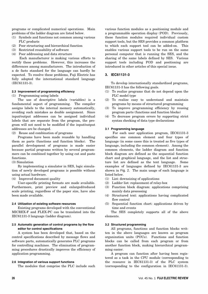
specifies one common element and four types oflanguage (in some cases this is treated as five types oflanguage, including the common element). Among thecommon elements, the ladder diagram and functionblock diagram are defined as the sequential functionchart and graphical language, and the list and struc-ture list are defined as the text language. Someexamples of languages defined by IEC61131-3 areshown in Fig. 2. The main usage of each language islisted below.(1) List: downsizing of applications(2) Ladder list: replacement of relay-box(3) Function block diagram: applications comprising
mainly data processing(4) Structured text: applications having complicated
flow control(5) Sequential function chart: applications driven by
time and eventsThe SES completely supports all of the above
elements.
3.2 Structured programmingAll programs, functions and function blocks writ-
ten in the above languages are known as programorganization units (POUs). Functions and functionblocks can be called from each program or fromanother function block, making hierarchical program-ming easier.
A program can function after having been regis-tered as a task in the CPU module (corresponding tothe resource in IEC61131-3) of the PLC system(corresponding to the configuration in IEC61131-3).
Integrated Programming Support System for MICREX-SX Series 27
Fig.2 IEC61131-3 language
Tasks are a means to activate and control programs.There are different types of tasks, such as: cyclic, fixed-cycle triggered, and event triggered. Several programscan be registered within the same task, and areprocessed in the registered sequence as if they were asingle program. Thus, large-scale and complicatedprocessing can be divided into smaller program blocks(POU)s, improving the programming efficiency largely.The IEC61131-3 software model is shown in Fig. 3.
For further details regarding the IEC61131-3,please refer to the “IEC1131-3 Handbook” (PLCopenJAPAN) or other reference.
4. Programming Design Support
4.1 Basic user interfaceThe basic user interface of the programming
support part (referred to as D300win hereafter) in theSES is known as the project tree. (See Fig. 4.) Aproject is the management unit for all the information
of programs in the D300win, and is assigned anarbitrary name. All programs developed by theD300win are managed by this project name.
In Fig. 4, the programming part is the logical POUsnode and the hardware condition setting part is thephysical hardware node, including subordinated nodes.In other words, the hardware condition setting partconsists of the parts for managing the configurationdefinition of the SX series, registering developedprograms as tasks, download the PLC, testing anddebugging, etc.
In addition, library nodes are provided to registerexisting developed projects for their reuse, and a datatype notebook is provided to generate and registercustomer-specific data type templates utilizing variousdata types supplied by the D300win.
4.2 ProgrammingProgramming is performed under the hierarchy of
a logical POU in program, function or function block
Fig.3 IEC61131-3 software model
LDANDORST
SWITCH1 SWITCH2
COND1VAR1
Inputcondition
Input value
Line Output side
Inputside
Block Output value
True/False valueof computation
Computationalinstruction
LAMP : = (SWITCH1 AND SWITCH2) OR SWITCH3;
FLAGOUT1
VAR2VAR3
MULEN ENO
ADDEN ENO
LAMP
STEP1
STEP2 N ACTION2
Initial step (Start of processing)
Action qualifier(Alphabetized specifica- tion of timing to execute action)
Action(Content of processing described by IL,ST,LD and FBD)
STEP3 N ACTION3
STEP4 N ACTION4
TIME_UP1
TIME_UP2
TIME_UP3
Transition (Conditions for transferring to the next step)
Step (One unit of a processing sequence)
TIME_UP4
SWITCH3
SWITCH1SWITCH2SWITCH3LAMP
(*Condition contact 1*) (*Condition contact 2*) (*Condition contact 3*) (*LAMP output*)
Comment
Label
Computational instruction(a) IL
(d) ST
(e) SFC
(c) FBD
(b) LD
Fig.4 D300win basic user interface
Program
POUs
Configu-ration
WS
Program
WS
Program
WS
FB FC
FC FB
LIB
POU
Resource (CPU)
Task
Machine 1 Machine 2 Machine n
I/O I/O I/O
Task
Globalmemory Access bus
Resource (CPU)
Task Task
Globalmemory
ProjectLibrary
Data format
Physical hardwareConfiguration
System(configuration) definition
TaskGlobal variable
ControlInstance
ProgramDescription work sheet
Variable work sheetCode work sheet
Logical POUs (Program Organization Units)
Resource (PC)
Program-ming part
Hardware condition setting part

Vol. 45 No. 1 FUJI ELECTRIC REVIEW28
units. A descriptive language can be specified for eachPOU. Each POU consists of three types of worksheets(description, variable and code). An example is shownin Fig. 5.
4.2.1 Programming with various languagesA text editor and a graphic editor are provided for
each text type language, such as the instruction listand structured text, and each graphic type language,such as the ladder diagram, function block diagramand sequential function chart. Each editor is automat-ically activated by the POU programming language.Examples of description by each language are shown inFig. 6. Comments can be described freely in eachlanguage.4.2.2 Programming assistance function
Various functions are provided for easier andquicker programming, several of which are introducedbelow.(1) Variable registration function
Variable declarations can be registered easily via aspecial dialog, or quickly via a text editor. (See Fig. 7.)(2) Error check and jump function
Errors in the developed program are detectedthrough compiling and displayed in the user errorwindow. By selecting an error message, display willjump to the error location in the program. By callingthe provided help function, the cause of the error and
Fig.5 Worksheet
Fig.6 Sample programs by D300win
Fig.7 Variable registration
Fig.8 Error check and jump
Fig.9 System configuration registration
Property
Para-meter

Integrated Programming Support System for MICREX-SX Series 29
countermeasures can be displayed. Figure 8 shows anexample.
4.3 Setting the program execution condition4.3.1 System configuration registration
The configuration of hardware modules that com-prise the SX system is registered and necessaryparameters for each module are set. The actualconfiguration can also be uploaded from the SXsystem. A configuration tree resembles the physicalimage of the system. (See Fig. 9.)4.3.2 Task registration
The CPU has three types of tasks: default, cyclicand event. Developed programs may be registered inany of these tasks freely. (See Fig. 10.) Programs ofother projects can also be registered, increasing theirreusability.4.3.3 Multi-CPU
In the case of multiple CPUs, the task registrationfor each CPU is the same as when only a single CPU is
used. (See Fig. 11.) Since each program can beregistered in any CPU, load dispersing and functiondistribution can be realized quite naturally.
5. Test and Debugging
5.1 Starting and stopping the controllerThe start/stop of the SX system and download of
programs is operated by control buttons in the resourcecontrol dialog. (See Fig. 12.)
5.2 MonitoringFour types of monitoring functions are provided.
5.2.1 Monitoring programThe monitoring program function monitors the
label values, contact status and coil status in theprogram. The format is the same as that generated by
Fig.11 Multi-CPU registration
Fig.10 Task registration
Arrangement
Cyclic task
Fixed-cycletask
Event task
Res
ourc
e
System definition
Fig.12 Resource control
Fig.13 Program monitoring
Controlbuttons
Project tree Program edition
Pro
gram
min
gP
rogr
am
debu
ggin
g
Instance tree Online program change
Monitoring/Debuggingdisplay
Fig.14 Watch list
Online value Variable name Instance name
Vol. 45 No. 1 FUJI ELECTRIC REVIEW30
set forcibly as a fixed value, independent from externalinput, or the output can be set forcibly as fixed value,independent from the results of computation. Theprogram control can enable or disable execution of eachprogram, which is very effective for debugging astructured program.
5.4 Online program changeThe path of each POU can be changed while the
monitoring program is running. (See Fig.13.) Changedprograms are downloaded automatically without stop-ping the CPU module.
6. Maintenance Support
6.1 Zip/Unzip of projectsDeveloped programs and large quantities of auxil-
iary information for each project can be compressedand zipped into a file as well as decompressed andunzipped.
6.2 PrintingThe following main functions are provided to
simplify and reduce user work for printing varioussoftware documents.6.2.1 Page layout
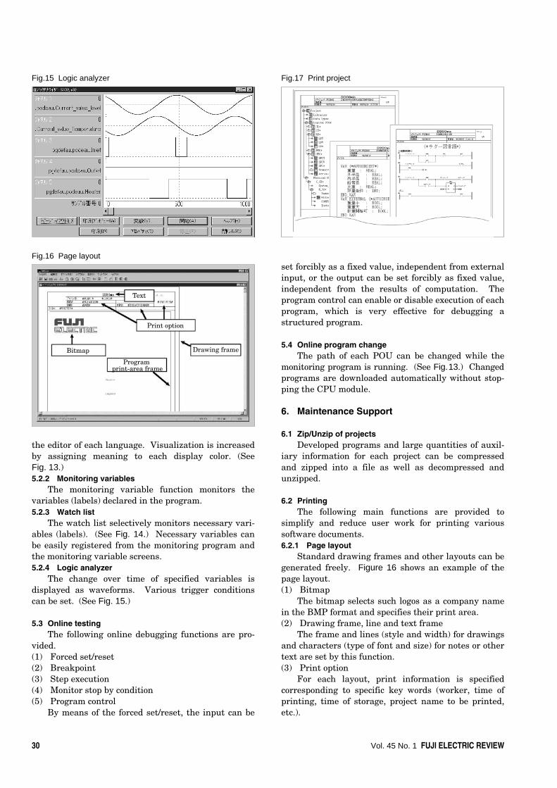
Standard drawing frames and other layouts can begenerated freely. Figure 16 shows an example of thepage layout.(1) Bitmap
The bitmap selects such logos as a company namein the BMP format and specifies their print area.(2) Drawing frame, line and text frame
The frame and lines (style and width) for drawingsand characters (type of font and size) for notes or othertext are set by this function.(3) Print option
For each layout, print information is specifiedcorresponding to specific key words (worker, time ofprinting, time of storage, project name to be printed,etc.).
the editor of each language. Visualization is increasedby assigning meaning to each display color. (SeeFig. 13.)5.2.2 Monitoring variables
The monitoring variable function monitors thevariables (labels) declared in the program.5.2.3 Watch list
The watch list selectively monitors necessary vari-ables (labels). (See Fig. 14.) Necessary variables canbe easily registered from the monitoring program andthe monitoring variable screens.5.2.4 Logic analyzer
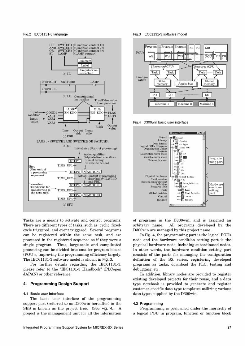
The change over time of specified variables isdisplayed as waveforms. Various trigger conditionscan be set. (See Fig. 15.)
5.3 Online testingThe following online debugging functions are pro-
vided.(1) Forced set/reset(2) Breakpoint(3) Step execution(4) Monitor stop by condition(5) Program control
By means of the forced set/reset, the input can be
Fig.17 Print projectFig.15 Logic analyzer
Fig.16 Page layout
Print option
Bitmap
Program print-area frame
Drawing frame
Text

Integrated Programming Support System for MICREX-SX Series 31
Fig.19 Loader network
Fig.20 Various types of help
MICREX-SX
MICREX-SX
D300win
P-link etc.
Ethernet etc.
MICREX-SX
MICREX-SX
P-link etc.
(4) Program print-area frameProgram print areas are specified.
6.2.2 Print previewThe print preview function makes it possible to
confirm, without printing, the print conditions of suchitems as project configurations or various worksheets.6.2.3 Print project
When printing different types of information suchas programs and auxiliary information, to minimizethe number of printing sheets, page feed can beomitted to minimize open spaces. A suitable pagelayout for printing can be selected from pre-preparedlayouts. Figure 17 shows an example.
6.3 PasswordD300win permits setting a password in the control-
ler. By setting the password, illegal program calls andsystem configuration changes are forbidden. Thus, thesystem is protected from negligent change or operationby a third party.
7. Reliability and Safety
When a failure occurs, identification of the failedpoint is urgently required. This identification is madeeasier by displaying messages hierarchically in thefollowing order: failure level → failed module →specific error cause within the module. (See Fig. 18.)
8. Assistance Functionality
8.1 Loader networkIn the past, Fuji Electric has provided connection
to a controller via a single network with P/PE links orother means. The D300win system, however, links theconnected SX system to a controller of another SXseries via the relayed connection of a maximum of twosystems by means of various networks (Ethernet*3,P/PE link etc.). Figure 19 shows an example connec-tion. This function enables program maintenance,debugging and monitoring in a high-level, sophisticat-ed network system.
8.2 Reverse compile and cross compileThe reverse compiler uploads programs from the
controller into D300win and redisplays them in theinstruction list format.
Variable information is downloaded in advancetogether with programs. Thereafter, if no project datais available, the variable information is uploadedtogether with programs again so the original variablelabels used during programming are displayed.
The cross compiler translates programs written ininstruction language into the ladder diagram, and thendisplays them.
8.3 IEC translatorIn conformance with IEC61131-3, the IEC transla-
tor translates existing programs (including statementsand comments such as device names) for Fuji Electric’sMICREX-F series and FLEX-PC series into instructionlist expressions. The IEC translator also translatessome system definitions and parameter settings intothe system definition of the SX system. This makes iteasy to transition from an existing system to an SXsystem.
*3 Ethernet: A registered trademark of Xerox Corp., USA
Fig.18 Reliability and safety
Details (of error)
Cause of error
Vol. 45 No. 1 FUJI ELECTRIC REVIEW32
9. Various Types of Help
In the D300win system, necessary help informa-tion for the particular work situation can be calledwith a simple operation. An environment is providedin which work can continue rapidly, with no need tokeep an operating manual on hand. The configurationand function of main help topics are introduced below.Figure 20 shows some examples of help information.(1) Configuration of the help information
(a) How to use and program the D300win(b) Description of functions and function blocks of
each PLC that is used, usage of each language,etc.
(c) Detailed description of error messages thatoccur during debugging and examples of coun-termeasures
(d) Description of the IEC61131-3 standard(2) Context sensitive help
Suitable help information according to the contextof the work can be called by a simple key operation.
10. Flow Editor for Control Specifications
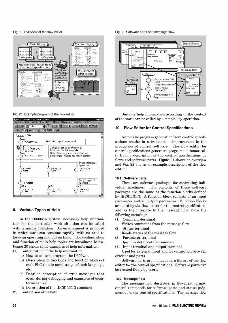
Automatic program generation from control specifi-cations results in a tremendous improvement in theproduction of control software. The flow editor forcontrol specifications generates programs automatical-ly from a description of the control specifications byflows and software parts. Figure 21 shows an overviewand Fig. 22 shows an example description of the floweditor.
10.1 Software partsThese are software packages for controlling indi-
vidual machines. The contents of these softwarepackages are the same as the function blocks definedby IEC61131-3. A function block consists of an inputparameter and an output parameter. Function blocksare used by the flow editor for the control specification,and as the interface to the message flow, have thefollowing meanings.(1) Command-terminal
Writes commands from the message flow(2) Status-terminal
Reads status of the message flow(3) Parameter-terminal
Specifies details of the command(4) Input terminal and output terminal
Used for external input and for connection betweenexterior and parts
Software parts are managed as a library of the floweditor for the control specifications. Software parts canbe created freely by users.
10.2 Message flowThe message flow describes, in flowchart format,
control commands for software parts and status judg-ments, i.e. the control specifications. The message flow
Fig.21 Overview of the flow editor
Fig.22 Example program of the flow editor
Fig.23 Software parts and message flow
積載工程
END END
異常処理
◎スタート★ON◎コンベアモータ★正転◎コンベア運転中★点灯◎容器バルブ★全開◎容器“空”検出LS★ON
◎コンベアモータ★運転中
◎トラック検出LS★ON
◎トラック ランプ★点灯
Yes No◎トラック ランプ★消灯
◎トラックランプ★消灯◎コンベアモータ★停止◎コンベア運転中★消灯
◎容器バルブ★全閉◎タイマ★60秒◎コンベアモータ★停止◎コンベア運転中★消灯
トラック検出
モータ
起動
停止
起動中
運転中
コンベヤ
起動逆転停止
正転中
逆転中
積載工程
END END
異常処理
◎スタート★ON◎コンベアモータ★正転◎コンベア運転中★点灯◎容器バルブ★全開◎容器“空”検出LS★ON
◎コンベアモータ★運転中
◎トラック検出LS★ON
◎トラック ランプ★点灯
Yes No◎トラック ランプ★消灯
◎トラックランプ★消灯◎コンベアモータ★停止◎コンベア運転中★消灯
◎容器バルブ★全閉◎タイマ★60秒◎コンベアモータ★停止◎コンベア運転中★消灯
トラック検出Windowscompatiblepersonal computer
AutomaticPLC programgeneration
Parts librery
Message flow (edited from the control specification)
Basic parts
Monitor(display)
+
User's parts
MICREX-SXSPH system
Parts library
Message flow
Driving motor No.3End
terminalNo.5
Start
: Driving motor No.3: Start: Delay time 50 seconds: End terminal No.5 ; ON
: Driving motor No.3: Stop
Limit swON
IN1
IN1 IN2 ON
IN2Start
Starting
Lock Stop Stop Starting
FWD
In operation
Start delayTON
IN Q
PTDelay time
MotorStartStop
Delay time
LockStop
FWD
In operationStarting
MotorStartStop
Delay time
LockStop
FWD
In operationStarting
Limit sw.on
IN1ON
IN2
Wait for input command
Judge start of conveyer 31Monitor for 20 secondsStart "conveyer error detectionprocedure" when an error occurs
Start stirringoperation
Judge type of product

Integrated Programming Support System for MICREX-SX Series 33
consists mainly of command elements (〇 elements)and judgment elements (◇ elements).
For example, if a part [motor] has a commandterminal [start], then [part: motor, command: rightrotation] is described using a command element in themessage flow. If waiting for input of a limit switch,[waiting condition: limit sw. on] is described using ajudgment element. The correlation between softwareparts and message flows is shown in Fig. 23.
10.3 MonitoringThe message flow can be used as a monitor display.
When a message flow being executed is shown on themonitor display, the step element being executedchanges color.
10.4 Setting conditions for the event triggerControl specifications must usually describe not
only how to handle normal operation, but also variouserrors. This makes it difficult to decipher a messageflow that includes many judgement elements for everyerror case.
The flow editor for control specifications solved thisproblem by separating normal operation from errone-ous operation by setting a condition area for an eventtrigger. Event and activation processes (anothermessage flow) are set by enclosing a portion of themessage flow within a rectangle. When an eventoccurs during program execution within the rectangle,progress of that message flow is stopped and aspecified message flow is activated. Thus, a messageflow that describes normal operation can be separatefrom, and not mixed with diverse processing forvarious error cases.
11. Conclusion
Features and functions of an integrated program-ming support system for the MICREX-SX series havebeen introduced above. The IEC standard language,structured programming and flow editor for the controlspecification, as proposed by the SES, can provide aninnovative environment to develop PLC programming,which is gradually approaching its limitations. In thefuture, Fuji Electric will enlarge the concept of SES,promote development mainly of the flow editor, andcontribute to improving the efficiency of applicationdevelopment for control systems.
Fig.24 Setting conditions for event trigger
Mixed normal/error process flow
Set
tin
g co
ndi
tion
s fo
r ev
ent
trig
ger
Normal process flow
Start
: Timer: Start: 10seconds
: Siren: Sound
: Driving motor: Stop
: Time expired
: Driving motor: Start: Delay time 1 second
: End terminal;ON
: End terminal;ON
Yes
Yes
NoNo
Start
: Driving motor: Start: Delay time 1 second10
seconds
Error process flow
Start
End
10 seconds elapsed
: Siren: Sound
: Driving motor: Stop
6Timer event type 6External event type
6Stop 6Return to the called position6Jump to an arbitrary element of the called position

* All brand names and product names in this journal might be trademarks or registered trademarks of their respective companies.