integrated numerical and experimental … example of the correlation between experimental and...
TRANSCRIPT
ASDJournal (2011), Vol. 2, No. 2, pp. 31–51∣∣∣ 31
Integrated Numerical and ExperimentalInvestigations of the Active/Passive AeroelasticConcepts on the European Research AeroelasticModel EuRAM
S. Kuzmina1
F. Ishmuratov2
M. Zichenkov3
V. Chedrik4
(Received: June 8, 2010. Revised: July 6, 2010. Accepted: July 15, 2011)
AbstractThe European Research Aeroelastic Model (EuRAM) was developed as an experi-mental platform for the demonstration of the new technical approaches and conceptsarising from the goals of the European 3AS (Active Aeroelastic Aircraft Structures)FP5 Project. The EuRAM demonstrator was designed and fabricated to test threeconcepts: Aeroelastic Wing Tip Controls, All-Movable Vertical Tail and SelectivelyDeformable Structures. Finite Element and aeroelastic models of the complete Eu-RAM airplane were created for prediction of the strength and aeroelastic behaviour,multidisciplinary optimization and updating following the wind tunnel tests. The com-plete EuRAM was tested in TsAGI’s T-104 wind tunnel. Components of the EuRAM(semi-wings with ordinary and new control surfaces, ordinary and all-movable verticaltails) were tested separately in different wind tunnels by partners of the 3AS Project.A wide range of multifunctional possibilities and reliability of the EuRAM model havebeen demonstrated. The analysis and tests of the EuRAM model proved its abilityto delay divergence and flutter onset, and also to withstand large gust loads, so al-lowing for a test campaign without high risk of model damage or failure. Results ofthe two-level approach for structural optimization of the EuRAM wing under stressand aeroelastic constraints are presented. It was demonstrated that the constraints onaileron effectiveness play a significant role in design of the wing structure, requiringextra weight to be added to compensate for the aeroelastic requirements. It was alsoshown that using of non-traditional wing tip ailerons reduces this weight increase.
1. Introduction
The European Research Aeroelastic Model (EuRAM) was developed as an ex-perimental platform for the demonstration of the new technical approaches andconcepts developed as part of the European 3AS (Active Aeroelastic AircraftStructures) FP5 Project [1, 2, 3]. 3AS aimed to improve the flight performance,economy and efficiency of aircraft through the development of active and passiveaeroelastic concepts. These concepts allow considerable reduction in aerody-namic drag, structural weight and operating costs. The EuRAM demonstrator,a four-engine wide body transport aeroelastic wind tunnel model of 1:10 lengthscale, span=5.7m and mass=200kg, was designed and fabricated to test threespecific concepts:
• Aeroelastic Wing Tip Controls (AWTC) - new control surfaces at the wingtip, forward of the elastic axis, to adjust the flexible wing deformation tothe optimum shape for minimum induced drag
• All-Movable Vertical Tail (AMVT) - replacement of the existing verticaltail by a smaller, all-movable surface with variable rotational attachmentstiffness. The rotational axis is located behind the elastic axis, and thetorsional stiffness can be adjusted to the flight condition
1 Deputy Head of Division, Aeroelasticity Department, TsAGI, Moscow2 Head of Division, Aeroelasticity Department, TsAGI, Moscow3 Deputy General Director, TsAGI, Moscow4 Head of Division, Static and Heat Strength Department, TsAGI, Moscow
doi:10.3293/asdj.2011.6
∣∣∣ 32 Integrated numerical and experimental investigations ...
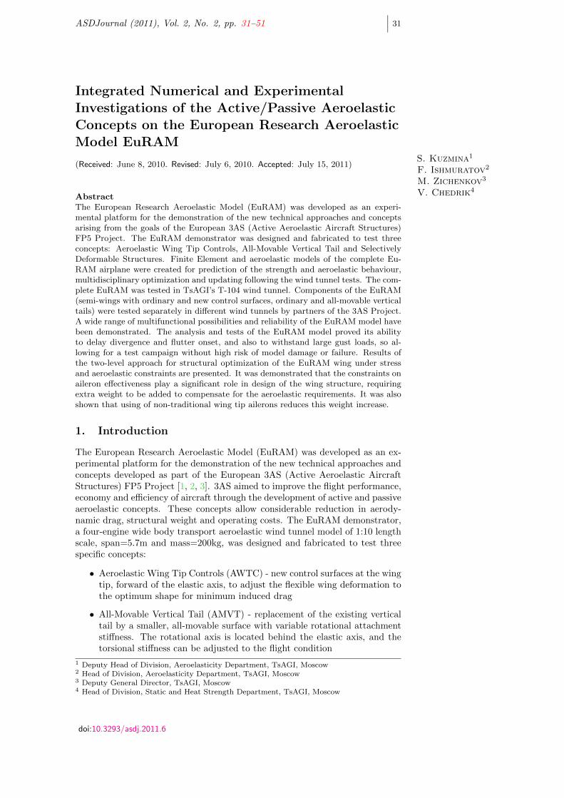
Figure 1: The completeEuRAM in TsAGI windtunnel T-104.
• Selectively Deformable Structures (SDS) - modification of the inner aileronusing a new kind of structure that allows large deformations with smallinternal forces, thereby creating a more continuous deformed shape
The complete model was tested in TsAGI’s T-103 and T-104 wind tunnels(Fig. 1). Components of the EuRAM (semi-wings with ordinary and newcontrol surfaces, ordinary and all-movable vertical tails) were tested separatelyin different wind tunnels by partners of the 3AS Project [4, 5]. Finite Element(FE) models of the complete EuRAM airplane were created for multidisciplinaryoptimization and analysis. In addition to the FE models (in NASTRAN format)the TsAGI software ARGON [6] was used for computing strength, static anddynamic aeroelasticity, and aeroservoelasticity characteristics. The ARGONcode was used to both predict the results and also to update analytical models.Updating the mathematical models of the elastic structure was carried out atdifferent stages on the basis of stiffness measurements, the Ground VibrationTest (GVT) and wind tunnel tests. Such an integrated approach allows validityof the results to be provided.
2. Design, manufacture and wind tunnel testing of theEuRAM
2.1 Requirements for the EuRAM and experimental facilities
The following main requirements for the demonstrator and testing were formu-lated according the 3AS project goals:
• modular structure with the possibility of semi-wings and vertical tailsbeing separately tested in different wind tunnels
• large scale and compartment-beam structure with easy changing of differ-ent configurations and control surfaces
• using actuators for ailerons and nontraditional surfaces dynamic control
• several different attachment types incorporated in the fuselage for adjust-ing the AMVT rotational stiffness and also basic vertical tail with rudder
• wind tunnel tests of the complete model on a balance and under ”free-free”conditions
• measurement of static aeroelasticity, flutter and aeroservoelastic charac-teristics for complete model and also separate components.
Vol. 2, No. 2, pp. 31–51 ASDJournal
S. Kuzmina, F. Ishmuratov, M. Zichenkov, V. Chedrik∣∣∣ 33
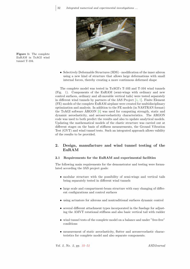
Figure 2: Fuselage cen-tral part (left), verti-cal tail structure (mid-dle) and forward aileron(right).
0
1000
2000
3000
4000
5000
6000
7000
8000
0.0 0.5 1.0 1.5 2.0 2.5 3.0
ExperimentCalculation
EI , N*m2
Span , m
Figure 3: Comparisonbetween experimental andcomputed wing stiffness.
2.2 Model design and manufacture
The T-flex 3-D CAD system was used for the design of new components of themodel and preparation of the necessary drawings. As examples, the centralparts of the fuselage, the tail structure and the forward aileron with pylon andintegrated actuator/sensor are shown in Fig. 2.
New control surfaces were employed that gain a positive effect from the wingelastic deformation [7]. The EuRAM fuselage, wings and tails were constructedusing aluminum beams with rectangular and H-shape cross-sections. Plywoodwas used as a main material for the compartment structures. The forwardaileron and pylon were of a carbon/fiber/plywood structure.
2.3 Laboratory tests
Laboratory measurements of stiffness, mass and modal characteristics of theEuRAM components, and a ground vibration test of the complete model con-figurations, were carried out. The qualification of the model parameters andpreparation data for creation of adequate mathematical models and their cor-rections was performed. An example of the correlation between experimentaland theoretical wing beam stiffness along the span is illustrated in Fig. 3.
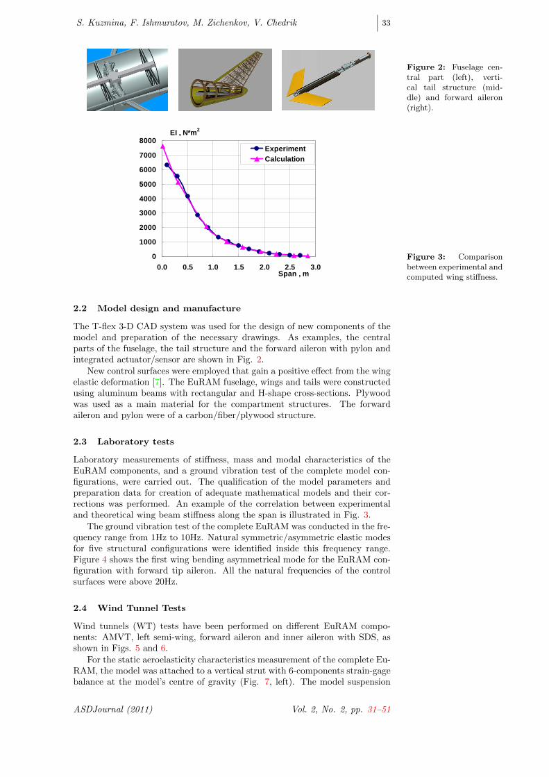
The ground vibration test of the complete EuRAM was conducted in the fre-quency range from 1Hz to 10Hz. Natural symmetric/asymmetric elastic modesfor five structural configurations were identified inside this frequency range.Figure 4 shows the first wing bending asymmetrical mode for the EuRAM con-figuration with forward tip aileron. All the natural frequencies of the controlsurfaces were above 20Hz.
2.4 Wind Tunnel Tests
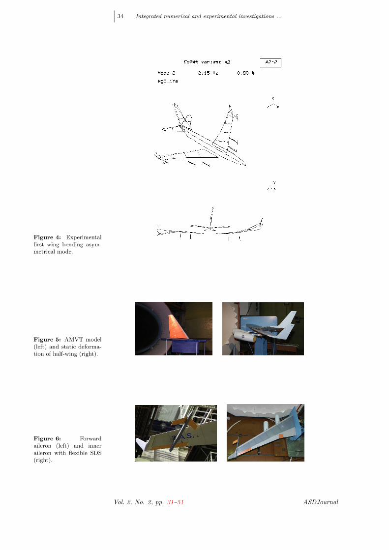
Wind tunnels (WT) tests have been performed on different EuRAM compo-nents: AMVT, left semi-wing, forward aileron and inner aileron with SDS, asshown in Figs. 5 and 6.
For the static aeroelasticity characteristics measurement of the complete Eu-RAM, the model was attached to a vertical strut with 6-components strain-gagebalance at the model’s centre of gravity (Fig. 7, left). The model suspension
ASDJournal (2011) Vol. 2, No. 2, pp. 31–51
∣∣∣ 34 Integrated numerical and experimental investigations ...
Figure 4: Experimentalfirst wing bending asym-metrical mode.
Figure 5: AMVT model(left) and static deforma-tion of half-wing (right).
Figure 6: Forwardaileron (left) and inneraileron with flexible SDS(right).
Vol. 2, No. 2, pp. 31–51 ASDJournal

S. Kuzmina, F. Ishmuratov, M. Zichenkov, V. Chedrik∣∣∣ 35
Figure 7: Static aeroe-lasticity test (left) andflutter test on the com-plete EuRAM (right) inWT T-104.
system enabled the angle of attack and sideslip angle to be changed. Deflec-tion angles of ailerons, tip and under wing forward ailerons, basic rudder andall-movable vertical tail could also be mechanically changed and fixed.
For the flutter tests in the T-104 tunnel, the complete EuRAM was supportedby a universal ”two points” cable low frequency suspension system designedin TsAGI especially for the investigation of dynamically scaled model fluttercharacteristics (Fig. 7, right). The suspension system provides five degrees offreedom for the model as a rigid body within a frequency range up to 1Hz.Choosing such suspension system structural parameters and geometry providesenough static and dynamic stability of the model so that it behaves as a rigidbody for all configurations. Signals of strain gauges and accelerometers, aswell as video and visual information, were used for the analysis of the modelflutter characteristics. The analysis of measured data showed that necessaryflutter margins are ensured for all test configurations of the EuRAM. Fluttercharacteristics of the model with the new wing tip surfaces attached somewhatdegraded for speed more than 34m/s; however, adequate safety margins werestill maintained.
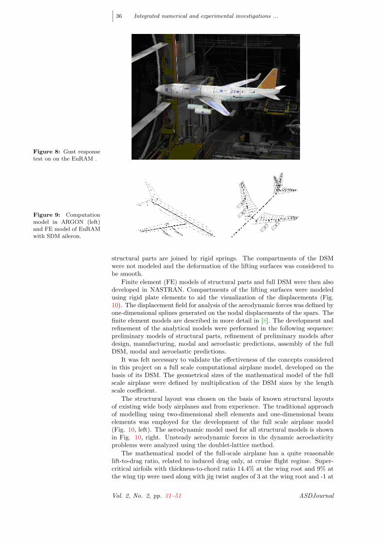
For the purposes of aeroservoelasticity investigations, the complete EuRAMwas installed in the T-104 wind tunnel on the same cable low frequency ”twopoints” suspension system as used for the flutter tests. The model was equippedwith miniature hydraulic actuators with maximum force of about 300N. ”Sen-sorex” inductive type displacement sensors with amplifiers were used both inthe actuator feedback loop and for measurement of the actuator rod displace-ments, ensuring adequate deflection of both ordinary and forward ailerons. Aspecial analog unit provided the necessary feedback loop for the ailerons’ actu-ator. Two PCs with analog-digital and digital-analog transfer blocks providedthe acquisition and control of sensor signals, excitation signals and control lawdigital filter for the closed loop experiments. The sampled frequency for theopen loop case was 250Hz, 1000Hz for the closed loop. A cascade of two wings,controlled by the PC driving a hydraulic actuator, in the entrance to the testsection allowed simulation a single gust of different harmonic gusts and randomturbulence (Fig. 8).
Two aspects of the active aeroelasticity concept were studied:
• use of wing elasticity for increase of the roll control characteristics anddecrease of the induced drag with aid of controls located forward of thewing stiffness axis;
• use of rotational elasticity of reduced size all-movable vertical tail for im-provement of lateral stability and controllability.
3. Computational Models
The computational beam model was designed using the ARGON software pack-age, leading to the manufacture of the beam-compartment Dynamically ScaledModels (DSM). The developed model was based on the method of prescribedforms (Ritz polynomial method) where the structural parts of the DSM weremodeled with bending/torsion beams and concentrated masses (Fig. 9). The
ASDJournal (2011) Vol. 2, No. 2, pp. 31–51
∣∣∣ 36 Integrated numerical and experimental investigations ...
Figure 8: Gust responsetest on on the EuRAM .
Figure 9: Computationmodel in ARGON (left)and FE model of EuRAMwith SDM aileron.
structural parts are joined by rigid springs. The compartments of the DSMwere not modeled and the deformation of the lifting surfaces was considered tobe smooth.
Finite element (FE) models of structural parts and full DSM were then alsodeveloped in NASTRAN. Compartments of the lifting surfaces were modeledusing rigid plate elements to aid the visualization of the displacements (Fig.10). The displacement field for analysis of the aerodynamic forces was defined byone-dimensional splines generated on the nodal displacements of the spars. Thefinite element models are described in more detail in [8]. The development andrefinement of the analytical models were performed in the following sequence:preliminary models of structural parts, refinement of preliminary models afterdesign, manufacturing, modal and aeroelastic predictions, assembly of the fullDSM, modal and aeroelastic predictions.
It was felt necessary to validate the effectiveness of the concepts consideredin this project on a full scale computational airplane model, developed on thebasis of its DSM. The geometrical sizes of the mathematical model of the fullscale airplane were defined by multiplication of the DSM sizes by the lengthscale coefficient.
The structural layout was chosen on the basis of known structural layoutsof existing wide body airplanes and from experience. The traditional approachof modelling using two-dimensional shell elements and one-dimensional beamelements was employed for the development of the full scale airplane model(Fig. 10, left). The aerodynamic model used for all structural models is shownin Fig. 10, right. Unsteady aerodynamic forces in the dynamic aeroelasticityproblems were analyzed using the doublet-lattice method.
The mathematical model of the full-scale airplane has a quite reasonablelift-to-drag ratio, related to induced drag only, at cruise flight regime. Super-critical airfoils with thickness-to-chord ratio 14.4% at the wing root and 9% atthe wing tip were used along with jig twist angles of 3 at the wing root and -1 at
Vol. 2, No. 2, pp. 31–51 ASDJournal

S. Kuzmina, F. Ishmuratov, M. Zichenkov, V. Chedrik∣∣∣ 37
Figure 10: FE model offull scale EuRAM (left)and aerodynamic model(right).
16.0
16.5
17.0
17.5
18.0
18.5
2 3 4 5 6
BaselineTAUWA
Lift-to-drag ratio Cruise flight: M=0.84, H=8400m
Angle of attack, deg
Figure 11: Comparisonof lift-to-drag ratio of fullaircraft for different con-figurations, TA-wing tipaileron, UWA-under wingaileron.
the wing tip. Figure 11 shows the comparison of lift-to-drag ratios for differentconfigurations. The configuration with tip aileron (TA) has a slightly greatervalue of lift-to-drag ratio mainly due to its larger effective aspect ratio.
4. Static Aeroelastic Characteristics
Most of the considered concepts in this work that aim to use aeroelastic deflec-tions in a positive way are mainly related to the static aeroelasticity charac-teristics. Therefore, considerable attention was paid to the static aeroelasticitystudies. Elastic displacements and streamwise twist angles along wing spar atangle of attack =5 and flow speed V=25m/s are shown in Figs. 12 and 13 with,and without, the structural weight included.
The wing tip displacement is 0.15 m in the upward direction, and decrease ofangles of attack in the tip section is =2.4 for analysis without account of gravityforces. Accounting for structural weight reduces the wing tip displacementalmost by 0.12 m. The roles of bending and torsion angles in the streamwiseangle of attack are shown in Fig. 14. The large contribution of the bending
0.00
0.04
0.08
0.12
0.16
0 0.5 1 1.5 2 2.5 3
without weightwith weight
Span, m
Displacement, m V=25 m/s, α=5 deg
Figure 12: Elastic dis-placements of EURAMmodel.
ASDJournal (2011) Vol. 2, No. 2, pp. 31–51

∣∣∣ 38 Integrated numerical and experimental investigations ...
Figure 13: Streamwisetwist angles along EU-RAM wing.
-3.0
-2.5
-2.0
-1.5
-1.0
-0.5
0.0
0 0.5 1 1.5 2 2.5 3
without weightwith weight
Stremwise twist angle, deg
Span, m
V=25 m/s, α=5 deg
Figure 14: Contributionof bending and torsion tothe streamwise angle ofattack.
-6
-4
-2
0
2
0 0.5 1 1.5 2 2.5 3
Twist angleBending angleStreamwise twist angle
Elastic increment of the angle, deg V=25 m/s, α =5 deg
Span,m
angle to the streamwise angle of attack can be seen.
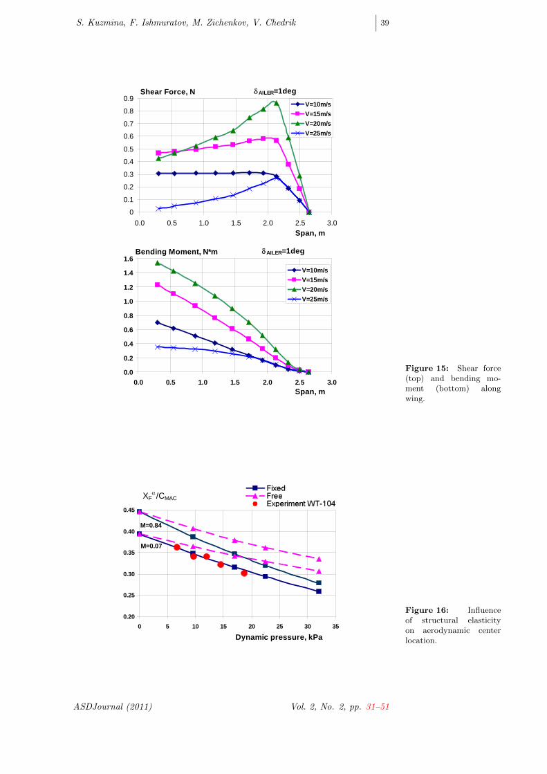
One of the most important static aeroelastic characteristics is the effective-ness of the outer aileron. Classically, this is reduced due to aeroelastic twist, andthe outer aileron achieved reversal on lift at flow speed V=25 m/s, and reversalon roll at flow speed V=36 m/s. A different interpretation of this phenomenonis presented in Fig. 15. Here the influence of flow speed and structural elastic-ity on distribution of aerodynamic forces is shown through consideration of afixed root wing structure with aileron deflection of 1 degree. The shear force inthe wing root achieves a maximum value at flow speeds in the range V=15-20m/s, but becomes practically zero at flow speed V=25 m/s. The bending mo-ment also achieves maximum value at flow speeds around V=20 m/s, and thendecreases for further increase of the flow speed.
It is necessary to bear in mind the use of the DSM static aeroelasticitycharacteristics for full scale airplane that they were defined for fixed structureof DSM. Additional inertial forces are applied to real structures in free flight,and they also cause additional displacements and redistribution of aerodynamicforces.
The influence of structural elasticity on the location of airplane aerodynamiccenter XF for the actual airplane scale of dynamic pressures is shown in Fig.16. The analytical and experimental results are in good agreement for fixedstructure in incompressible airflow (M=0.07). The characteristics of free-freestructures are different from fixed structure. Also, it is necessary to take intoaccount the influence of Mach number on the full scale airplane behavior, andFig. 16 shows that for in-cruise flight M=0.84 the location of aerodynamiccenter of the full scale airplane in free flight is significantly different from thelocation found in the wind tunnel tests. Note the good comparison between theanalytical and experimental results.
Vol. 2, No. 2, pp. 31–51 ASDJournal
S. Kuzmina, F. Ishmuratov, M. Zichenkov, V. Chedrik∣∣∣ 39
0
0.1
0.2
0.3
0.4
0.5
0.6
0.7
0.8
0.9
0.0 0.5 1.0 1.5 2.0 2.5 3.0
V=10m/sV=15m/sV=20m/sV=25m/s
Shear Force, N
Span, m
δAILER=1deg
0.0
0.2
0.4
0.6
0.8
1.0
1.2
1.4
1.6
0.0 0.5 1.0 1.5 2.0 2.5 3.0
V=10m/sV=15m/sV=20m/sV=25m/s
Bending Moment, N*m
Span, m
δAILER=1deg
Figure 15: Shear force(top) and bending mo-ment (bottom) alongwing.
0.20
0.25
0.30
0.35
0.40
0.45
0 5 10 15 20 25 30 35
Dynamic pressure, kPa
M=0.84
M=0.07
XFα/CMAC
Figure 16: Influenceof structural elasticityon aerodynamic centerlocation.
ASDJournal (2011) Vol. 2, No. 2, pp. 31–51

∣∣∣ 40 Integrated numerical and experimental investigations ...
Figure 17: Roll ef-fectiveness of wing tipaileron.
-0.025
-0.020
-0.015
-0.010
-0.005
0.0000 10 20 30 40
M=0.07 Fixed M=0.84 FixedM=0.07 Free M=0.84 FreeM=0.07 Fixed
Analysis:
Experiment T-103:
Dynamic pressure, kPa
mxδ - Roll effectiveness of tip aileron
5. Aeroelastic Wing Tip Controls Concept
The objective of the concept is to investigate new types of control surface thatgenerate an active elastic deformation of the wing leading to desired aerody-namic characteristics. Figure 17 shows the comparison for the roll effectivenessmx of the wing tip aileron. For the fixed structure the analytical results arein a good agreement with the experimental ones (recalculated for scales of theactual airplane). Unlike a regular aileron the effectiveness of the wing tip aileronis practically not decreased. On a free structure, the inertial forces arising be-cause of roll angular acceleration twist the wing to ”useful” angles. Therefore,the effectiveness of the wing tip aileron on full scale airplane increases. How-ever, inertial forces should be taken into account for the full scale (FS) structurebecause the DSM is not similar to full scale airplane on mass-inertial character-istics.
5.1 Dynamic effectiveness of control surfaces
One of the key aspects of the active aeroelasticity concept is the active controlsystem. Frequency response functions (FRF) for load factors at various struc-tural sections, and for wing root loads, are computed to evaluate the possibilitiesof using of AWTC for active control system. Results of this analysis were foundto be in satisfactory agreement with the experimental data. For example, acomparison of FRF for load factor at the wing tip (Nw) and wing root bend-ing moment (Mb) due to symmetrical harmonic deflection of regular aileronsis shown in Figs 18 and 19 for airflow speed V=22m/s. The figures show thatanalysis characteristics agree well with the experimental data both on amplitudeand phase. Some of the disagreement in amplitude can be explained by the wellknown peculiarity of linear panel aerodynamics that amplifies somewhat thelifting properties. Also, some difference in structural damping may have to beconsidered. It is interesting to compare the dynamic effectiveness of differentwing control surfaces: regular (basic) aileron, tip aileron (TA), and aileron on apylon under wing (UWA). Their effectiveness for the gust load alleviation sys-tem was studied in [9]. Here we consider a comparison of the aeroelastic wingtip controls (AWTC) effectiveness on wing root bending moment in frequencydomain for different airflow speeds (Figs 20 and 21). The dynamic effectivenessof the basic aileron remains greater at airspeed V=22m/s, but at V=30m/s theAWTC has a considerably higher effectiveness in the frequency range of thefirst natural elastic mode. The regular aileron has larger effectiveness in thefrequency range of higher elastic modes.
5.2 Strength and aeroelastic structural optimization of the EuRAMwing using a two-level approach
Structural optimization was performed for the EuRAM full scale airplane withdifferent types of aeroelastic wing tip control surfaces (AWTC). The resultsobtained demonstrate the influence of the AWTC on the optimum structural
Vol. 2, No. 2, pp. 31–51 ASDJournal

S. Kuzmina, F. Ishmuratov, M. Zichenkov, V. Chedrik∣∣∣ 41
Basic AileronV=22 m/s NW/δAiler, g/deg
Exper (left) Exper (right)Analysis
Figure 18: FRF for loadfactor at the wing tipdue to regular aileronoscillation.
Basic AileronV=22 m/s
Exper (left) Exper (right)Analysis
Mb/δAiler, Nm/deg
f, Hz
Figure 19: FRF for wingroot bending moment dueto regular aileron oscilla-tion .
AilerTA UWA
Mb/δ, Nm/deg
Figure 20: Dynamic ef-fectiveness of AWTC atV=22m/s.
ASDJournal (2011) Vol. 2, No. 2, pp. 31–51

∣∣∣ 42 Integrated numerical and experimental investigations ...
Figure 21: Dynamic ef-fectiveness of AWTC atV=30m/s.
Ailer TA UWA
Mb/δ, Nm/deg
weight and aeroelastic characteristics. A comparative analysis of baseline con-figuration with the new ”active aeroelastic” configurations was conducted. Theproblem of preliminary design of an aircraft structure is to define structuralsizes that will ensure minimum weight while satisfying the numerous multi-disciplinary constraints. These constraints are of different types for many loadconditions in disciplines such as strength, static and dynamic aeroelasticity. Theresponses in the disciplines can be analyzed by programs which use structuralmodels of different fidelity and different approach.
The ARGON multidisciplinary system integrates several aircraft disciplines:
• linear aerodynamics
• analysis of maneuver and dynamic loads on elastic structure
• structural analysis
• modal analysis
• static aeroelasticity
• flutter
• aeroservoelasticity
The problems of aeroelasticity and loads calculation are solved by usingthe discrete-continual model of prescribed forms (first level model). The finiteelement model (second level model) is used for detailed evaluation of stressesand displacements of structure. The design procedure based on the two-levelapproach is shown in Fig. 22.
The aeroelastic/strength design cycle starts with calculation of aerodynamicand inertial loads for various parameters of maneuvers. Optimization underboth stress constraints (for these loads) and aeroelasticity constraints is per-formed using the first level model. Loads for the optimized elastic structureare then recalculated again, and a new optimization is carried out. The resultsfound using the first-level model can be used for determination of extreme loadcases for the structural parts, along with their corresponding load distribution,determination stiffness requirements and preliminary structural sizing of thelifting surface structure.
The load cases for the full-scale EuRAM airplane were chosen according toprototype data and the results of parametric load and stress analysis in theARGON computational first and second level models. The primary structure of
Vol. 2, No. 2, pp. 31–51 ASDJournal

S. Kuzmina, F. Ishmuratov, M. Zichenkov, V. Chedrik∣∣∣ 43
First-level model (PF method)
Aerodynamics
Loads
Aeroelasticity
Second-level Model (FE Method)
StructuralAnalysis
Structural Optimization under Strength,Stiffness and Buckling Constraints
Verifying Stress, Buckling and Aeroelasticity Requirements Exit
Reducing FEM Matrices
First-level model (PF method)
Aerodynamics
Loads
Aeroelasticity
Second-level Model (FE Method)
StructuralAnalysis
Structural Optimization under Strength,Stiffness and Buckling Constraints
Verifying Stress, Buckling and Aeroelasticity Requirements Exit
Reducing FEM Matrices
Figure 22: Flow dia-gram of ARGON system.
V Mach number Dynamic pressure Altitudekm/h EAS kPa mVD=690 MD=0.90 qD=22.5 7400VC=600 MC=0.84 qC=17.0 8400VA=450 MA=0.37 qA=9.57 0
Table 1: Designparameters
the wing was considered for flight load cases to study the AWTC characteristics.The following design speeds, Mach numbers and altitudes were chosen (Table1).
The design weight for the load analysis was chosen to equal 215 tons, in-cuding 80% mass of the fuel. As a result of parametric flight load analysis, thefollowing design load cases (LC: A, C, D) had been determined: 1) Maximumlift coefficient and maximum load factor at MA, qA near ground; 2) Maximumload factor at MC , qC; 3) Maximum load factor at MD , qD; 4) Half of max-imum load factor at MC , qC and deflection of the wing control surfaces toprovide roll rate of 10 degrees per second. The fixed and free parameters oftrim analysis are shown in Table 2.
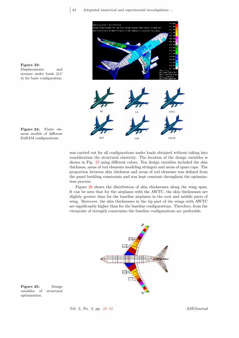
The load cases 1-3 were the same for different AWTC configurations. TheLC 4 is modified for TA and UWA configurations: parameters TA and UWA areused instead of AILERON. Ensuring the strength under quasi-steady loads forthese cases leads to a material distribution which is close to results of recalcu-lations of DSM stiffness according to similarity scale coefficients. For example,Fig. 23 shows displacements and stresses under loads (LC 4) for the basic config-uration. An application of these load cases for the wing structural optimizationunder strength and aeroelasticity constraints for different AWTC configurationswas considered in [10] using ARGON second level (FE) model.
The full-scale airplane models with different types and location of AWTCare presented in Fig. 24, where the following abbreviations are used:
BL - baseline airplane with basic aileron,BLP - baseline airplane with winglets,TA - airplane with wing tip aileron,TAP - airplane with wing tip aileron plus winglets,UWA - airplane with under wing aileron,UWAP - airplane with under wing aileron plus winglets.Initially, the structural optimization of the wing-box with stress constraints
LC N. Fixed Trim parameters Free Trim parameters1 nz = 2.5, ωy = 0, ω̇y = 0 α, δElevator
2 nz = 2.5, ωy 6= 0, ω̇y = 0 α, δElevator
3 nz = 2.5, ωy 6= 0, ω̇y = 0 α, δElevator
4 nz = 1.25, ωx = 10deg/s, ωy = 0, ω̇y = 0 α, δElevator, δAileron
Table 2: Parameters oftrim analysis
ASDJournal (2011) Vol. 2, No. 2, pp. 31–51
∣∣∣ 44 Integrated numerical and experimental investigations ...
Figure 23:Displacements andstresses under loads (LC4) for basic configuration.
Figure 24: Finite ele-ment models of differentEuRAM configurations.
BL
TA
UWA
BLP
TAP
UWAP
was carried out for all configurations under loads obtained without taking intoconsideration the structural elasticity. The location of the design variables isshown in Fig. 25 using different colors. Ten design variables included the skinthickness, areas of rod elements modeling stringers and areas of spars caps. Theproportion between skin thickness and areas of rod elements was defined fromthe panel buckling constraints and was kept constant throughout the optimiza-tion process.
Figure 26 shows the distribution of skin thicknesses along the wing span.It can be seen that for the airplanes with the AWTC, the skin thicknesses areslightly greater than for the baseline airplanes in the root and middle parts ofwing. Moreover, the skin thicknesses in the tip part of the wings with AWTCare significantly higher than for the baseline configurations. Therefore, from theviewpoint of strength constraints the baseline configurations are preferable.
Figure 25: Designvariables of structuraloptimization.
Vol. 2, No. 2, pp. 31–51 ASDJournal

S. Kuzmina, F. Ishmuratov, M. Zichenkov, V. Chedrik∣∣∣ 45
0.000
0.001
0.002
0.003
0.004
0.005
0.006
0.007
0.008
0 5 10 15 20 25 30
Wing span, m
Thic
knes
ses,
mBLPTAPUWAPInitial design
Figure 26: Designvariables of structuraloptimization.
0.001
0.002
0.003
0.004
0.005
0 5 10 15 20 25 30Wing span, m
Thic
knes
s, m
BLТА
Figure 27: Skinthicknesses afterstress/aeroelasticoptimization.
The analyses of static aeroelasticity characteristics had shown that thereis an aileron reversal of the baseline configuration, whereas the EuRAM withthe AWTC has sufficient effectiveness in roll. Obviously, the optimized base-line configuration under loads that accounts for structural elasticity has smallerthicknesses and aileron reversal takes place. The optimization of the airplanewith the tip aileron (TA) was carried by imposing only stress constraints for theloads on the elastic structure. The optimum weight of the wing panels of struc-ture is about 30% less than the optimum one with ”rigid” loads. Aeroelasticanalysis showed that the tip aileron effectiveness is sufficient for the consideredflight regimes. Structural optimization with stress constraint and aileron effec-tiveness constraint was then performed for the baseline configuration withoutwinglets under the loads on the elastic structure. The weight was only about 8%less than for the case of ”rigid” loads. Such a small decrease of the weight (incomparison with 30% for the airplane with TA) is due to an additional increaseof thicknesses in root and tip of the wing to compensate for the violation of theaeroelastic constraints. The distribution of thicknesses for two configurationsis shown in Fig. 27. In total, the weight of the wing with AWTC is slightly(about 4%) less than the weight of the wing with regular ailerons. An additionaladvantage of AWTC is that the control surfaces located forward from the wingleading edge can be used to reduce the manoeuvre loads using their adaptivedeflection (when the wing tip aileron is deflected proportionally to the airplaneangle of attack).
6. All-Movable Vertical Tail concept
The objective of the concept was to develop and validate novel approaches forincreasing the effectiveness of vertical tail surface through the use of an adaptiveattachment. All-movable vertical tails are a known design feature [11]. They
ASDJournal (2011) Vol. 2, No. 2, pp. 31–51

∣∣∣ 46 Integrated numerical and experimental investigations ...
Table 3: Vertical tail ge-ometric parameters
VT AMVTRoot chord c0 and c0a [m] 0.900 0.74Span [m] 1.00 0.80χ0 [degs] 46.86 38.0Tip chord c1 and c1a [m] 0.250 0.19CMAC−V T and CMAC−AMV T 0.636 0.52X(25% MAC) 0.59 0.59
were already used in the early days of supersonic flight. For example, they wereused on famous airplanes such as the XB-70 and SR-71. Today, the upper partof the vertical tail (VT) on the F-117 is all- movable. An advantage of theadaptive attachment stiffness concept for all-movable tail surfaces is that thesize of the tail surface can be reduced by a factor corresponding to the chosenaeroelastic effectiveness increase. The same design failure criteria with respectto flutter can be applied as on conventional designs.
6.1 Geometry and aeroelastic characteristics of basic VT and AMVT
Finite Element models of the traditional vertical tail with rudder, new all-movable fin and of the complete EuRAM airplane were created for multidisci-plinary optimization and analysis. In addition to the FE models (in NASTRANformat), the domestic TsAGI software ARGON was used for the design and op-timization of the shape and attachment stiffness of AMVT. The main designrequirements were defined as follows.
• area of AMVT equals to 65% area of basic VT
• the same position of 25% MAC point for basic VT and AMVT in X di-rection
• the same aspect ratio
• the same profiles
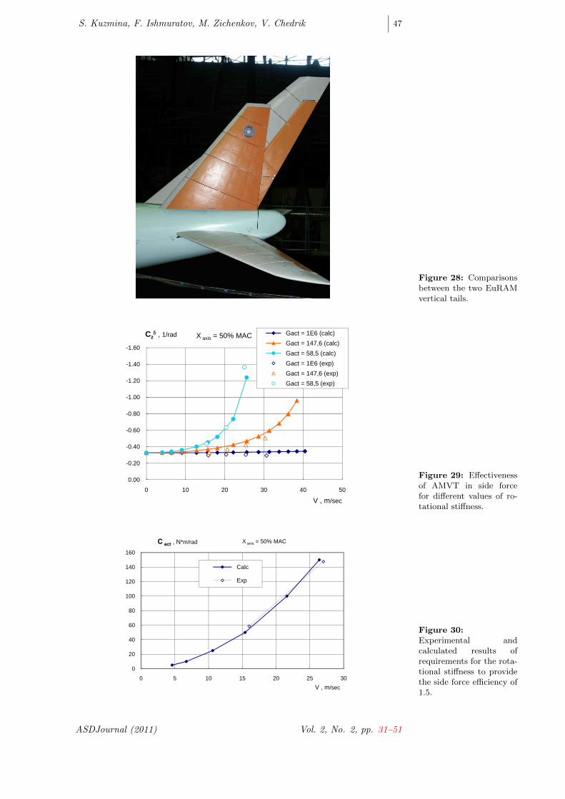
Minimization of the AMVT structural weight, and accordingly decrease ofits stiffness properties, have been restricted by flutter safety requirements in theconsidered range of rotational stiffness. A structural optimization procedure wasperformed taking into account the aeroelasticity constraints by using ARGONcode in order to determine the geometry and stiffness parameters of AMVT [12].The photo of the two vertical tails are shown in Fig. 28. Geometric parametersare compared in Table 3.
6.2 Comparison between analysis and experimental results
The aerodynamic side force was computed for an elastic VT, which was con-nected to the fixed point through rotational springs of different stiffness. Theside force increases due to rotational stiffness for axis positions greater than30%Cmac and slightly decreases due to the VT’s own elasticity at high speeds(Fig. 29). Figure 30 shows the required stiffness for 1.5 of side force efficiency.
Comparative flutter characteristics of isolated AMVT and complete modelwith AMVT are shown in Figs 31 and 32. Anti-symmetrical oscillations of thecomplete DSM change their behavior in the airflow in the presence of adaptiveattached AMVT. Dependence of divergence on the flutter speeds on AMVTrotational stiffness, G, are presented for rotational axis position of 40% MAC.Two additional flutter modes have appeared in the case of the complete airplanemodel. Low-frequency flutter mode ”AMVT rotation + rigid body yaw” appearsfor the complete EuRAM DSM (”Flutter 0.3-1.0 Hz”) instead of divergence forisolated AMVT at low rotational stiffness. Due to interaction of rotationaloscillations of AMVT with second antisymmetrical wing bending mode and
Vol. 2, No. 2, pp. 31–51 ASDJournal
S. Kuzmina, F. Ishmuratov, M. Zichenkov, V. Chedrik∣∣∣ 47
Figure 28: Comparisonsbetween the two EuRAMvertical tails.
-1.60
-1.40
-1.20
-1.00
-0.80
-0.60
-0.40
-0.20
0.000 10 20 30 40 50
Gact = 1E6 (calc)Gact = 147,6 (calc)Gact = 58,5 (calc)Gact = 1E6 (exp)Gact = 147,6 (exp)Gact = 58,5 (exp)
Czδ , 1/rad
V , m/sec
X axis = 50% MAC
Figure 29: Effectivenessof AMVT in side forcefor different values of ro-tational stiffness.
0
20
40
60
80
100
120
140
160
0 5 10 15 20 25 30
Calc
Exp
С act , N*m/rad
V , m/sec
X axis = 50% MAC
Figure 30:Experimental andcalculated results ofrequirements for the rota-tional stiffness to providethe side force efficiency of1.5.
ASDJournal (2011) Vol. 2, No. 2, pp. 31–51

∣∣∣ 48 Integrated numerical and experimental investigations ...
Figure 31: Flutter anddivergence of isolatedAMVT (left) and ofcomplete AMVT (right).
0
10
20
30
40
50
60
0 50 100 150 200
Divergence Flutter 10 Hz
X AXIS = 40% MAC, Isolated AVMT
Rotational stiffness, N*m/rad
V , m/s
0
10
20
30
40
50
60
0 50 100 150 200
Flutter 3.7-4 HzFlutter 0.3-1.0 HzFlutter 10 HzRequired Speed
V , m/s X AXIS = 40% MAC, Complete Model
Rotational stiffness, N*m/rad
Figure 32: AMVTdivergence and flutterspeeds vs. rotationalstiffness.
0
10
20
30
40
50
60
70
80
90
0 100 200 300 400 500
Divergence_AnalysisFlutter_AnalysisFlutter_ExperimentDivergence_Experiment
V, m/s
Rotational stiffness, N*m/rad
Xaxis=50%MAC
fuselage horizontal bending, a new flutter mode (”Flutter 3.7-4.0 Hz”, Figure41) appeared. Figure 31 also illustrates the required flow speed versus rotationalstiffness for which side stability and controllability is increased by 1.5 times. Itcan be seen that the flutter margin is not sufficient for stiffness in the rangeof 20-30 Nm/rad. An augmentation of flutter margin can be reached by useof active damping in the AMVT actuator. Comparisons of the numerical andexperimental results are represented in Fig. 32.
7. Selective Deformable Structure Concept
The objective of the new passive structural design concept is to develop andinvestigate a slotless connection using ”smart” elements of selective deformablestructure [13, 14] that allows large continuous deformations of a load-carryingstructure. A flexible connection of the aileron leading edge with the wing boxwas designed for the dynamically scaled model EuRAM. In addition to the or-dinary (regular) inner aileron the adaptive aileron was designed (Fig. 33). Thestatic aeroelasticity properties of the adaptive aileron were studied experimen-tally and theoretically. The main attention was given to behaviour of the wing,where the adaptive aileron has been connected.
7.1 Wind tunnel test
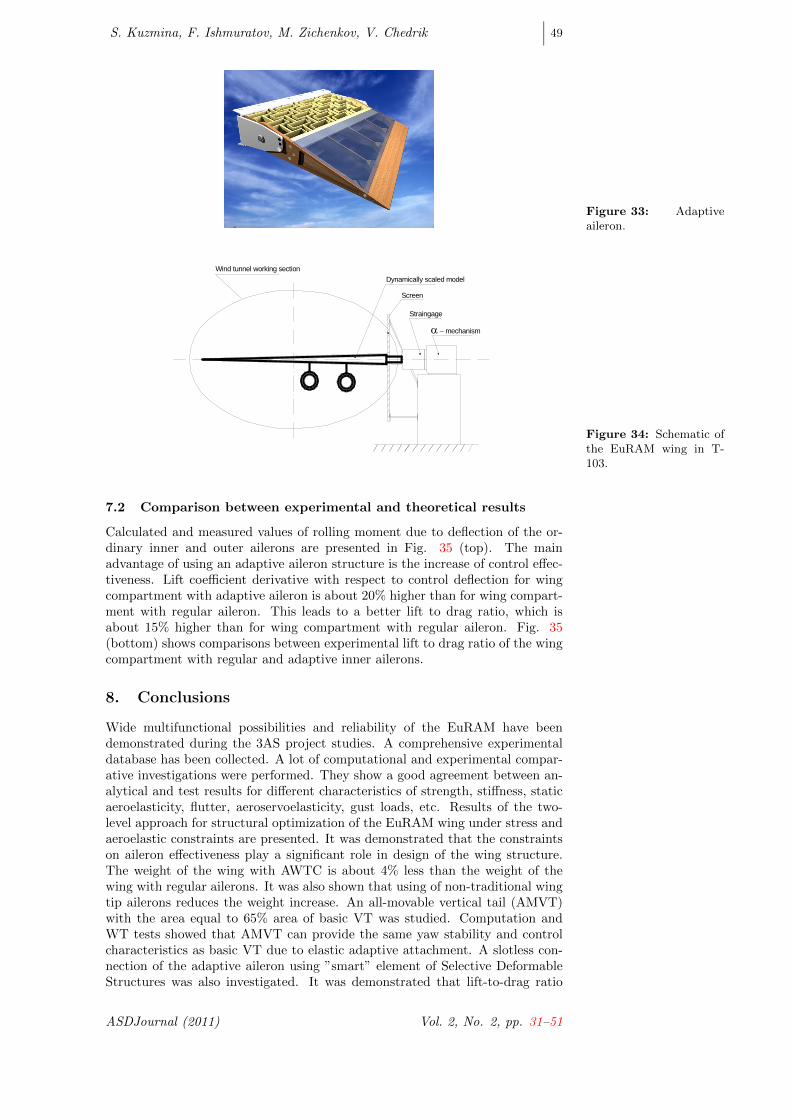
Wind tunnel tests of the EuRAM wing model with the adaptive and ordinary in-ner aileron were performed in TsAGI subsonic wind tunnel T-103. The adaptiveaileron was fabricated using the SDS technology. Figure 34 shows the EuRAMwing with inner and outer ailerons, and with T 103 equipment (external straingage balance of the wing).
Vol. 2, No. 2, pp. 31–51 ASDJournal
S. Kuzmina, F. Ishmuratov, M. Zichenkov, V. Chedrik∣∣∣ 49
Figure 33: Adaptiveaileron.
Dynamically scaled model
α − mechanism
Wind tunnel working section
Straingage
Screen
Figure 34: Schematic ofthe EuRAM wing in T-103.
7.2 Comparison between experimental and theoretical results
Calculated and measured values of rolling moment due to deflection of the or-dinary inner and outer ailerons are presented in Fig. 35 (top). The mainadvantage of using an adaptive aileron structure is the increase of control effec-tiveness. Lift coefficient derivative with respect to control deflection for wingcompartment with adaptive aileron is about 20% higher than for wing compart-ment with regular aileron. This leads to a better lift to drag ratio, which isabout 15% higher than for wing compartment with regular aileron. Fig. 35(bottom) shows comparisons between experimental lift to drag ratio of the wingcompartment with regular and adaptive inner ailerons.
8. Conclusions
Wide multifunctional possibilities and reliability of the EuRAM have beendemonstrated during the 3AS project studies. A comprehensive experimentaldatabase has been collected. A lot of computational and experimental compar-ative investigations were performed. They show a good agreement between an-alytical and test results for different characteristics of strength, stiffness, staticaeroelasticity, flutter, aeroservoelasticity, gust loads, etc. Results of the two-level approach for structural optimization of the EuRAM wing under stress andaeroelastic constraints are presented. It was demonstrated that the constraintson aileron effectiveness play a significant role in design of the wing structure.The weight of the wing with AWTC is about 4% less than the weight of thewing with regular ailerons. It was also shown that using of non-traditional wingtip ailerons reduces the weight increase. An all-movable vertical tail (AMVT)with the area equal to 65% area of basic VT was studied. Computation andWT tests showed that AMVT can provide the same yaw stability and controlcharacteristics as basic VT due to elastic adaptive attachment. A slotless con-nection of the adaptive aileron using ”smart” element of Selective DeformableStructures was also investigated. It was demonstrated that lift-to-drag ratio
ASDJournal (2011) Vol. 2, No. 2, pp. 31–51

∣∣∣ 50 Integrated numerical and experimental investigations ...
Figure 35: Rolling mo-ment coefficient of Eu-RAM wing (top) andLift to drag ratio of Eu-RAM wing compartment(bottom).
-0.10
-0.08
-0.06
-0.04
-0.02
0.00
0.020 10 20 30 40
Outer aileron Inner aileron Inner aileron (exp)
V, m/s
mxδ, 1/rad
0
5
10
15
20
25
0 10 20 30 40 50
Adaptive inner aileron
Regular inner aileron
CL/CX
V, m/s
for wing compartment with adaptive aileron is about 15% higher than for wingcompartment with regular aileron. The EuRAM has good potential for use infuture projects in aeroelasticity.
Acknowledgements
The work was done under financial support in the framework of the 5th FP ECProject ”Active Aeroelastic Aircraft Structures (3AS)” and ISTC Grant N.2050.Authors thank project partners for the opportunity for fulfillment of interestingresearches and attentive discussion of obtained results.
References
[1] S. Kuzmina, G. Amiryants, J. Schweiger, J. Cooper, M. Amprikidis, andO. Sensburg. Review and outlook on active and passive aeroelastic designconcepts for future aircraft. In 23rd Congress ICAS, Toronto, Canada,2002.
[2] J. Simpson, A. Suleman, and J. Cooper. Review of european researchproject ”active aeroelastic aircraft structures”. In IFASD Conference, Mu-nich, 2005.
Vol. 2, No. 2, pp. 31–51 ASDJournal

S. Kuzmina, F. Ishmuratov, M. Zichenkov, V. Chedrik∣∣∣ 51
[3] G.A. Amiryants, M.Ch. Zichenkov, Yu.M. Mullov, and S.V. Shalaev. De-sign, manufacture and wind tunnel testing of the multi-functional euro-pean research aeroelastic model (euram). In EUCASS Conference, Moscow,2005.
[4] J. Chcrdle, V. Chedrik, J. Malecek, and Yu. Naiko. Analysis and experi-mental validation of an aeroelastic semi-wing model. In EUCASS Confer-ence, Moscow, 2005.
[5] S. Ameduri, M. Amprikidis, J. Cooper, and J. San Millan. Adaptive stiff-ness system for an active aeroelastic all-moving vertical tail. In EUCASSConference, Moscow, 2005.
[6] F. Ishmuratov and V. Chedrik. Argon code: Structural aeroelastic analysisand optimization. In IFASD Conference, Amsterdam, 2003.
[7] V. Chedrik, F. Ishmuratov, and S. Kuzmina. Numerical studies of aeroelas-ticity/strength/ aerodynamic for the european research aeroelastic model.In EUCASS Conference, Moscow, 2005.
[8] A.B. Kudryashov, F.Z. Ishmuratov, V. Chedrik, S. Kuzmina, andJ. Schweiger. Main aspects of fe modelling and active aeroelasticity con-cept analysis of the passenger aircraft (euram). In Symposium: AviationTechnologies of the XXI Century (ASTEK-03), Zhukovsky, Russia, 2003.
[9] M. Karpel and B. Moulin. Gust loads alleviation using special controlsurfaces. In IFASD Conference, Munich, 2005.
[10] S. Kuzmina, V. Chedrik, and F.Z. Ishmuratov. Strength and aeroelasticstructural optimization of aircraft lifting surfaces using two-level approach.In 6th World Congress of Structural and Multidisciplinary Optimization,Rio de Janeiro, Brazil, 2005.
[11] J. Schweiger, F. Weiss, and Th. Kullrich. Active aeroelastic design of a ver-tical tail for a fighter aircraft. In 8th AIAA/NASA/ISSMO Symposium onMultidisciplinary Analysis and Optimization, CP-4848, Long Beach, CA,2000.
[12] S. Kuzmina, F. Ishmuratov, M. Zichenkov, V. Kuzmin, and J. Schweiger.Integrated numerical and experimental investigations of the active adaptiveall-movable vertical tail concept. In IFASD Conference, Munich, 2005.
[13] G. Amiryants. Selectively deformable structures; new concept in engineer-ing. In ICAS Conference, Melbourne, 1998.
[14] G. Kawiecki and G. Amiryants. Adaptive selectively deformable structuresanalysis. In IFASD Conference, Amsterdam, 2003.
ASDJournal (2011) Vol. 2, No. 2, pp. 31–51