integrated monolithic 3d mems scanner for switchable real time...
TRANSCRIPT
Integrated monolithic 3D MEMS scanner for switchable real time vertical/horizontal cross-
sectional imaging
Haijun Li,1 Xiyu Duan,2 Zhen Qiu,1,2 Quan Zhou,2 Katsuo Kurabayashi,3 Kenn R. Oldham,3 and Thomas D. Wang1,2,3*
1Department of Internal Medicine, Division of Gastroenterology, University of Michigan, Ann Arbor, MI, USA 2Department of Biomedical Engineering, University of Michigan, Ann Arbor, MI, USA 3Department of Mechanical Engineering, University of Michigan, Ann Arbor, MI, USA
Abstract: We present an integrated monolithic, electrostatic 3D MEMS scanner with a compact chip size of 3.2 × 2.9 mm2. Use of parametric excitation near resonance frequencies produced large optical deflection angles up to ± 27° and ± 28.5° in the X- and Y-axes and displacements up to 510 μm in the Z-axis with low drive voltages at atmospheric pressure. When packaged in a dual axes confocal endomicroscope, horizontal and vertical cross-sectional images can be collected seamlessly in tissue with a large field-of-view of >1 × 1 mm2 and 1 × 0.41 mm2, respectively, at 5 frames/sec.
©2016 Optical Society of America
OCIS codes: (230.4685) Optical microelectromechanical devices; (180.1790) Confocal microscopy; (230.4040) Mirrors.
References and links
1. T. D. Wang, J. Van Dam, J. M. Crawford, E. A. Preisinger, Y. Wang, and M. S. Feld, “Fluorescence endoscopic imaging of human colonic adenomas,” Gastroenterology 111(5), 1182–1191 (1996).
2. N. Barker, R. A. Ridgway, J. H. van Es, M. van de Wetering, H. Begthel, M. van den Born, E. Danenberg, A. R. Clarke, O. J. Sansom, and H. Clevers, “Crypt stem cells as the cells-of-origin of intestinal cancer,” Nature 457(7229), 608–611 (2009).
3. M. J. Mandella and T. D. Wang, “Dual axes confocal microscopy,” In Tuchin VV Ed., Handbook of Photonics for Medical Science (CRC Press, 2010), 481–508.
4. Z. Qiu, Z. Liu, X. Duan, S. Khondee, B. Joshi, M. J. Mandella, K. Oldham, K. Kurabayashi, and T. D. Wang, “Targeted vertical cross-sectional imaging with handheld near-infrared dual axes confocal fluorescence endomicroscope,” Biomed. Opt. Express 4(2), 322–330 (2013).
5. S. Tang, W. Jung, D. McCormick, T. Xie, J. Su, Y.-C. Ahn, B. J. Tromberg, and Z. Chen, “Design and implementation of fiber-based multiphoton endoscopy with microelectromechanical systems scanning,” J. Biomed. Opt. 14(3), 034005 (2009).
6. J. Sun, S. Guo, L. Wu, L. Liu, S. W. Choe, B. S. Sorg, and H. Xie, “3D in vivo optical coherence tomography based on a low-voltage, large-scan-range 2D MEMS mirror,” Opt. Express 18(12), 12065–12075 (2010).
7. X. Duan, H. Li, Z. Qiu, B. P. Joshi, A. Pant, A. Smith, K. Kurabayashi, K. R. Oldham, and T. D. Wang, “MEMS-based multiphoton endomicroscope for repetitive imaging of mouse colon,” Biomed. Opt. Express 6(8), 3074–3083 (2015).
8. L. Liu, E. Wang, X. Zhang, W. Liang, X. Li, and H. Xie, “MEMS-based 3D confocal scanning microendoscope using MEMS scanners for both lateral and axial scan,” Sens. Actuators A Phys. 215, 89–95 (2014).
9. J. Jeong, M. J. Mandella, G. S. Kino, C. H. Contag, and O. Solgaard, “3-D MEMS scanning system for dual-axis confocal microendoscopy,” 16th International Conference on Optical MEMS and Nanophotonics, 71–72 (2011).
10. Y. Zhu, W. Liu, K. Jia, W. Liao, and H. Xie, “A piezoelectric unimorph actuator based tip-tilt-piston micromirror with high fill factor and small tilt and lateral shift,” Sens. Actuators 167(2), 495–501 (2011).
11. E. E. Aktakka, R. L. Peterson, and K. Najafi, “A 3-DOF piezoelectric micro vibratory stage based on bulk-PZT/silicon crab-leg suspensions,” MEMS IEEE Int. Conf. Micro. Electro. Mech. Syst. 576–579 (2013).
12. J. Choi, Z. Qiu, C.-H. Rhee, T. Wang, and K. Oldham, “A three-degree-of-freedom thin-film PZT-actuated microactuator with large out-of-plane displacement,” J. Micromech. Microeng. 24(7), 1–35 (2014).
13. V. Milanović, G. Matus, and D. T. McCormick, “Gimbal-less monolithic silicon actuators for tip-tilt-piston micromirror applications,” IEEE J. Sel. Top. Quantum Electron. 10(3), 462–471 (2004).
#253557 Received 16 Nov 2015; revised 12 Jan 2016; accepted 23 Jan 2016; published 27 Jan 2016 © 2016 OSA 8 Feb 2016 | Vol. 24, No. 3 | DOI:10.1364/OE.24.002145 | OPTICS EXPRESS 2145
14. W. Liao, W. Liu, Y. Zhu, Y. Tang, B. Wang, and H. Xie, “A tip-tilt-piston micromirror with symmetrical lateral-shift-free piezoelectric actuators,” IEEE Sens. J. 13(8), 2873–2881 (2013).
15. Y. Wu, Y. Zhang, J. Xi, M. J. Li, and X. Li, “Fiber-optic nonlinear endomicroscopy with focus scanning by using shape memory alloy actuation,” J. Biomed. Opt. 15(6), 060506 (2010).
16. K. Lee, K. Krisnamoorthy, K. Yu, and O. Solgaard, “Single-crystalline silicon micromirrors actuated by self-aligned vertical electrostatic comb drives with piston-motion and rotational capabilities,” Sens. Actuators A Phys. 114(2-3), 423–428 (2004).
17. L. Wu and H. Xie, “A large vertical displacement electrothermal bimorph microactuator with very small lateral shift,” Sens. Actuators A Phys. 145–146, 371–379 (2008).
18. M. Feldmann, A. Waldschik, and S. Büttgenbach, “Electromagnetic micro-actuators, micro-motors, and micro-robots,” Proc. SPIE 6798, Microelectronics. Design, Technology, and Packaging III, 679811 (2007).
19. K. Turner, S. Miller, P. Hartwell, N. C. MacDonald, S. H. Strogatz, and S. G. Adams, “Five parametric resonances in a microelectromechanical system,” Nature 396(6707), 149–152 (1998).
20. K. S. Chen, A. Ayon, and S. M. Spearing, “Controlling and testing the fracture strength of silicon on the mesoscale,” J. Am. Ceram. Soc. 83(6), 1476–1484 (2000).
21. T. Klose, D. Kunze, T. Sandner, H. Schenk, H. Lakner, A. Schneider, and P. Schneider, “Stress optimization of a micromechanical torsional spring,” NSTI-Nanotech 3, 602–605 (2005).
22. C. Ataman and H. Urey, “Nonlinear frequency response of comb-driven microscanners,” Proc. SPIE 5348, MOEMS Display and Imaging Systems II, 166–174 (2004).
23. A. D. Rakić, “Algorithm for the determination of intrinsic optical constants of metal films: application to aluminum,” Appl. Opt. 34(22), 4755–4767 (1995).
24. W. Piyawattanametha, H. Ra, Z. Qiu, S. Friedland, J. T. C. Liu, K. Loewke, G. S. Kino, O. Solgaard, T. D. Wang, M. J. Mandella, and C. H. Contag, “In vivo near-infrared dual-axis confocal microendoscopy in the human lower gastrointestinal tract,” J. Biomed. Opt. 17(2), 021102 (2012).
25. J. F. Rhoads, S. W. Shaw, K. L. Turner, J. Moehlis, B. E. DeMartini, and W. Zhang, “Generalized parametric resonance in electrostatically actuated microelectromechanical oscillators,” J. Sound Vibrat. 296(4-5), 797–829 (2006).
26. T. Sandner, T. Grasshoff, and H. Schenk, “Translatory MEMS actuator with extraordinary large stroke for optical path length modulation,” 2010 Int. Conf. Opt. MEMS Nanophotonics 7930, 25–26 (2010).
1. Introduction
Endomicroscopes perform optical sectioning, and can collect in vivo images in the epithelium of hollow organs, such as colon, with sub-cellular resolution. This thin layer of tissue has high metabolic activity, and is the origin of many cancers. In the normal condition, the vertical dimension (perpendicular to tissue surface) of the epithelium is ∼400 μm in depth [1]. Current clinical instruments use a flexible optical fiber coupled to an objective lens in a single axis configuration, and visualizes in horizontal planes (parallel to tissue surface) only. Imaging in the vertical plane is of great importance because epithelial cells naturally differentiate in this direction [2]. Also, cancer cells originate in this layer and invade downwards. The vertical view can accurately localize where disease is occurring relative to the tissue surface. Pathologists use this orientation to stage progression of early cancer.
Imaging in the vertical plane requires an optical detection method with sufficient dynamic range to detect light over many orders of magnitude because of cumulative effects from tissue absorption and scattering. The dual axes confocal architecture uses two separate beams and objectives that are oriented off-axis to illuminate and collect light, and provide high dynamic range that rolls off exponentially in the axial (Z-axis) direction [3]. Also, this design uses low numerical aperture objectives to produce a long working distance that provides space for a miniature scanner to be located in the post-objective position. This mechanism allows for the optics to be scaled down to millimeter dimensions and to generate a very large field-of-view (FOV) compared to other endomicroscope designs. We have previously used this design to demonstrate vertical cross-sectional images using a 10 mm diameter instrument with a large, bulky PZT actuator to perform axial scanning [4].
For general purpose use, a miniature scanner that provides large angular deflections and sizable axial displacements is needed to image in either the horizontal or vertical plane. Microscanners based on microelectromechanical systems (MEMS) technology have been developed and widely used in endomicroscopy [5–7]. Most MEMS scanners produce in-plane 2D scanning to collect horizontal images only. An actuator must either move the objective
#253557 Received 16 Nov 2015; revised 12 Jan 2016; accepted 23 Jan 2016; published 27 Jan 2016 © 2016 OSA 8 Feb 2016 | Vol. 24, No. 3 | DOI:10.1364/OE.24.002145 | OPTICS EXPRESS 2146
lens [8] or scan out-of-plane [9] to collect vertical images. Several MEMS-based 3D scanners have been developed that can enable tip–tilt–piston motions [6,10–14], but these devices suffer from coupling between different directions of motion and/or cannot reach as high scanning speeds as current technology. To our knowledge, this is the first report of an integrated, monolithic MEMS scanner that collect images in either the horizontal or vertical plane and can achieve a depth that spans the epithelium of hollow organs.
Other scanning technologies are being developed for use in endomicroscopes to perform in vivo imaging. While these designs are quite good at lateral scanning, they have limitations in ability to scan with large out-of-plane displacement. Shape memory alloy (nitinol) based actuators are used in first generation confocal endomicroscopes to provide an axial displacement of ~250 µm [15]. Other MEMS-based electrostatic scanners have been developed with fast response times at low voltages but have not achieved adequate Z-axis motion [16]. Electrothermal devices can provide large axial displacements (>600 µm) at low voltages (∼5 V) but the response time is too slow for in vivo imaging [17]. Piezoelectric scanners in development can achieve large DC displacements, but 3D fast-axis scanning frequencies are limited to date, and fabrication complexity is high [10–12]. Electromagnetic scanners have been developed with fast response times and good displacement, but this technology is difficult to scale down in size for most endomicroscopy applications [18].
2. Methods
2.1 Scanner design
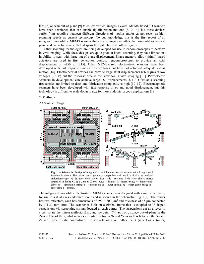
Fig. 1. – Schematic. Design of integrated monolithic electrostatic scanner with 3 degrees-of-freedom is shown. The mirror has a geometry compatible with use in a dual axes confocal endomicroscope. a) En face view shows front side structures. Side view shows mirror operation in the b) X-, c) Y-, and d) Z-axes. Key: i – islands; is – inner spring; ic – inner comb-drive; ss – serpentine spring; s – suspension; os – outer spring; oc – outer comb-drive; la – lever arm; g – gimbal.
The integrated, monolithic electrostatic MEMS scanner was designed with a mirror geometry for use in a dual axes endomicroscope and is shown in the schematic, Fig. 1(a). The mirror has two reflectors, each has dimensions of 690 × 700 μm2 and thickness of 45 μm connected by a 1.31 mm strut. The scanner is built on a gimbal frame that is coupled to U-shaped suspensions via serpentine springs located at each corner. The suspensions act as a lever to either rotate the mirror (reflectors) around the outer (Y-) axis or displace out-of-plane in the Z-axis. Use of the gimbal reduces cross-talk between X- and Y- as well as between the X- and Z- axes. Electrostatic comb-drives provide rotation about either the X (inner) or Y (outer)
#253557 Received 16 Nov 2015; revised 12 Jan 2016; accepted 23 Jan 2016; published 27 Jan 2016 © 2016 OSA 8 Feb 2016 | Vol. 24, No. 3 | DOI:10.1364/OE.24.002145 | OPTICS EXPRESS 2147
axis, respectively, and consist of comb-fingers patterned in the device layer with a thickness of 45 μm that are alternately movable and stationary with a gap of 5 μm.
Scanner operation is based on parametric resonance. The drive signal has frequency near at 2ω0/n (ω0 is the natural frequency of each mode, n is an integer ≥1) [19]. The side views show how the scanner rotates around the X and Y-axes and displaces in the Z-axis, Fig. 1(b)-1(d), respectively. We introduced a 500 μm deep cavity on the back side of the substrate to provide space for the mirror to displace vertically with large deflection angles. The backside islands with a thickness of ~120 μm are partially released, and the backside silicon (500 μm) and the buried silicon oxide (1 μm) under the movable structure and the fixed combs (45 μm) are fully etched and released. Trenches are etched with deep and narrow dimensions in the device layer to electrically isolate the drive signals between the inner and outer comb-drives. Back side islands are etched to provide mechanical support for the gimbal.
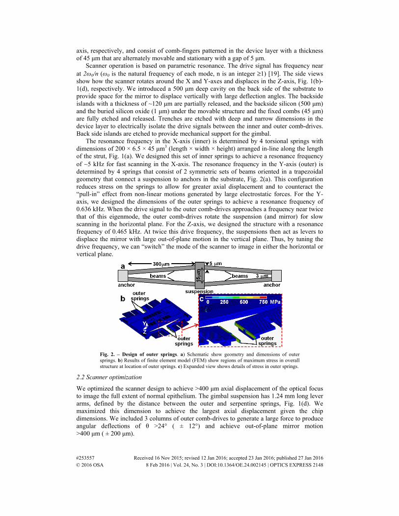
The resonance frequency in the X-axis (inner) is determined by 4 torsional springs with dimensions of 200 × 6.5 × 45 μm3 (length × width × height) arranged in-line along the length of the strut, Fig. 1(a). We designed this set of inner springs to achieve a resonance frequency of ∼5 kHz for fast scanning in the X-axis. The resonance frequency in the Y-axis (outer) is determined by 4 springs that consist of 2 symmetric sets of beams oriented in a trapezoidal geometry that connect a suspension to anchors in the substrate, Fig. 2(a). This configuration reduces stress on the springs to allow for greater axial displacement and to counteract the “pull-in” effect from non-linear motions generated by large electrostatic forces. For the Y-axis, we designed the dimensions of the outer springs to achieve a resonance frequency of 0.636 kHz. When the drive signal to the outer comb-drives approaches a frequency near twice that of this eigenmode, the outer comb-drives rotate the suspension (and mirror) for slow scanning in the horizontal plane. For the Z-axis, we designed the structure with a resonance frequency of 0.465 kHz. At twice this drive frequency, the suspensions then act as levers to displace the mirror with large out-of-plane motion in the vertical plane. Thus, by tuning the drive frequency, we can “switch” the mode of the scanner to image in either the horizontal or vertical plane.
Fig. 2. – Design of outer springs. a) Schematic show geometry and dimensions of outer springs. b) Results of finite element model (FEM) show regions of maximum stress in overall structure at location of outer springs. c) Expanded view shows details of stress in outer springs.
2.2 Scanner optimization
We optimized the scanner design to achieve >400 μm axial displacement of the optical focus to image the full extent of normal epithelium. The gimbal suspension has 1.24 mm long lever arms, defined by the distance between the outer and serpentine springs, Fig. 1(d). We maximized this dimension to achieve the largest axial displacement given the chip dimensions. We included 3 columns of outer comb-drives to generate a large force to produce angular deflections of θ >24° ( ± 12°) and achieve out-of-plane mirror motion >400 μm ( ± 200 μm).
#253557 Received 16 Nov 2015; revised 12 Jan 2016; accepted 23 Jan 2016; published 27 Jan 2016 © 2016 OSA 8 Feb 2016 | Vol. 24, No. 3 | DOI:10.1364/OE.24.002145 | OPTICS EXPRESS 2148
Large axial displacements will introduce structural stress that can weaken device integrity. We developed a finite element model (FEM) using ANSYS software to assess the distribution of stress throughout the scanner. From our model, we found a maximum stress of ~750 MPa at either end of the outer springs with ± 400 μm axial displacement, Fig. 2(b), shown more clearly in the expanded view, Fig. 2(c). This value is well below the limit for fracture strength of single crystal silicon [20,21]. This result supports the design of the outer springs to safely and repetitively achieve large out-of-plane displacements.
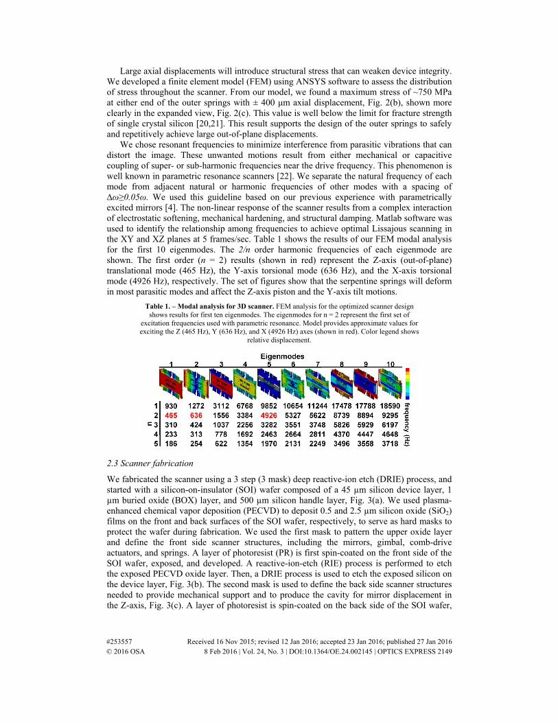
We chose resonant frequencies to minimize interference from parasitic vibrations that can distort the image. These unwanted motions result from either mechanical or capacitive coupling of super- or sub-harmonic frequencies near the drive frequency. This phenomenon is well known in parametric resonance scanners [22]. We separate the natural frequency of each mode from adjacent natural or harmonic frequencies of other modes with a spacing of ∆ω≥0.05ω. We used this guideline based on our previous experience with parametrically excited mirrors [4]. The non-linear response of the scanner results from a complex interaction of electrostatic softening, mechanical hardening, and structural damping. Matlab software was used to identify the relationship among frequencies to achieve optimal Lissajous scanning in the XY and XZ planes at 5 frames/sec. Table 1 shows the results of our FEM modal analysis for the first 10 eigenmodes. The 2/n order harmonic frequencies of each eigenmode are shown. The first order (n = 2) results (shown in red) represent the Z-axis (out-of-plane) translational mode (465 Hz), the Y-axis torsional mode (636 Hz), and the X-axis torsional mode (4926 Hz), respectively. The set of figures show that the serpentine springs will deform in most parasitic modes and affect the Z-axis piston and the Y-axis tilt motions.
Table 1. – Modal analysis for 3D scanner. FEM analysis for the optimized scanner design shows results for first ten eigenmodes. The eigenmodes for n = 2 represent the first set of
excitation frequencies used with parametric resonance. Model provides approximate values for exciting the Z (465 Hz), Y (636 Hz), and X (4926 Hz) axes (shown in red). Color legend shows
relative displacement.
2.3 Scanner fabrication
We fabricated the scanner using a 3 step (3 mask) deep reactive-ion etch (DRIE) process, and started with a silicon-on-insulator (SOI) wafer composed of a 45 µm silicon device layer, 1 µm buried oxide (BOX) layer, and 500 µm silicon handle layer, Fig. 3(a). We used plasma-enhanced chemical vapor deposition (PECVD) to deposit 0.5 and 2.5 µm silicon oxide (SiO2) films on the front and back surfaces of the SOI wafer, respectively, to serve as hard masks to protect the wafer during fabrication. We used the first mask to pattern the upper oxide layer and define the front side scanner structures, including the mirrors, gimbal, comb-drive actuators, and springs. A layer of photoresist (PR) is first spin-coated on the front side of the SOI wafer, exposed, and developed. A reactive-ion-etch (RIE) process is performed to etch the exposed PECVD oxide layer. Then, a DRIE process is used to etch the exposed silicon on the device layer, Fig. 3(b). The second mask is used to define the back side scanner structures needed to provide mechanical support and to produce the cavity for mirror displacement in the Z-axis, Fig. 3(c). A layer of photoresist is spin-coated on the back side of the SOI wafer,
#253557 Received 16 Nov 2015; revised 12 Jan 2016; accepted 23 Jan 2016; published 27 Jan 2016 © 2016 OSA 8 Feb 2016 | Vol. 24, No. 3 | DOI:10.1364/OE.24.002145 | OPTICS EXPRESS 2149
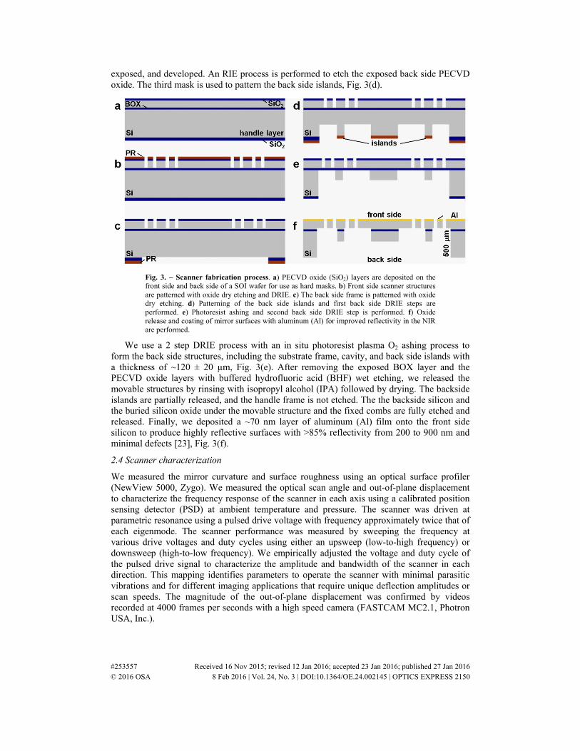
exposed, and developed. An RIE process is performed to etch the exposed back side PECVD oxide. The third mask is used to pattern the back side islands, Fig. 3(d).
Fig. 3. – Scanner fabrication process. a) PECVD oxide (SiO2) layers are deposited on the front side and back side of a SOI wafer for use as hard masks. b) Front side scanner structures are patterned with oxide dry etching and DRIE. c) The back side frame is patterned with oxide dry etching. d) Patterning of the back side islands and first back side DRIE steps are performed. e) Photoresist ashing and second back side DRIE step is performed. f) Oxide release and coating of mirror surfaces with aluminum (Al) for improved reflectivity in the NIR are performed.
We use a 2 step DRIE process with an in situ photoresist plasma O2 ashing process to form the back side structures, including the substrate frame, cavity, and back side islands with a thickness of ~120 ± 20 µm, Fig. 3(e). After removing the exposed BOX layer and the PECVD oxide layers with buffered hydrofluoric acid (BHF) wet etching, we released the movable structures by rinsing with isopropyl alcohol (IPA) followed by drying. The backside islands are partially released, and the handle frame is not etched. The the backside silicon and the buried silicon oxide under the movable structure and the fixed combs are fully etched and released. Finally, we deposited a ~70 nm layer of aluminum (Al) film onto the front side silicon to produce highly reflective surfaces with >85% reflectivity from 200 to 900 nm and minimal defects [23], Fig. 3(f).
2.4 Scanner characterization
We measured the mirror curvature and surface roughness using an optical surface profiler (NewView 5000, Zygo). We measured the optical scan angle and out-of-plane displacement to characterize the frequency response of the scanner in each axis using a calibrated position sensing detector (PSD) at ambient temperature and pressure. The scanner was driven at parametric resonance using a pulsed drive voltage with frequency approximately twice that of each eigenmode. The scanner performance was measured by sweeping the frequency at various drive voltages and duty cycles using either an upsweep (low-to-high frequency) or downsweep (high-to-low frequency). We empirically adjusted the voltage and duty cycle of the pulsed drive signal to characterize the amplitude and bandwidth of the scanner in each direction. This mapping identifies parameters to operate the scanner with minimal parasitic vibrations and for different imaging applications that require unique deflection amplitudes or scan speeds. The magnitude of the out-of-plane displacement was confirmed by videos recorded at 4000 frames per seconds with a high speed camera (FASTCAM MC2.1, Photron USA, Inc.).
#253557 Received 16 Nov 2015; revised 12 Jan 2016; accepted 23 Jan 2016; published 27 Jan 2016 © 2016 OSA 8 Feb 2016 | Vol. 24, No. 3 | DOI:10.1364/OE.24.002145 | OPTICS EXPRESS 2150
2.5 Confocal images
We verified scanner performance by packaging the device in a 10 mm diameter dual axes confocal fluorescence endomicroscope [4]. This ex vivo study was approved by the Institutional Review Board (IRB) at the University of Michigan. Fresh specimens of human colonic mucosa were obtained from the tissue procurement core with written informed consent from the patient. The specimen was snap frozen with dry ice (−70 °C) and stored at −80 °C in a sterile cryogenic vial. Prior to imaging, tissue was thawed on ice and cut from the mucosal side of the sample (<5 mm thick). IRDye 800CW carboxylate (LI-COR Biosciences) at a concentration of 0.03 mg/mL (30 µM) in water with 5% DMSO was topically administered for 1 hour. Excess dye was rinsed away with water prior to imaging. The specimen was placed onto the endomicroscope. Fluorescence images were collected by tuning the drive frequency to “switch” between vertical (XZ) and horizontal (XY) planes. Horizontal cross-sectional images were collected at various depths using a bulk PZT actuator.
3. Results
3.1 Scanner fabrication
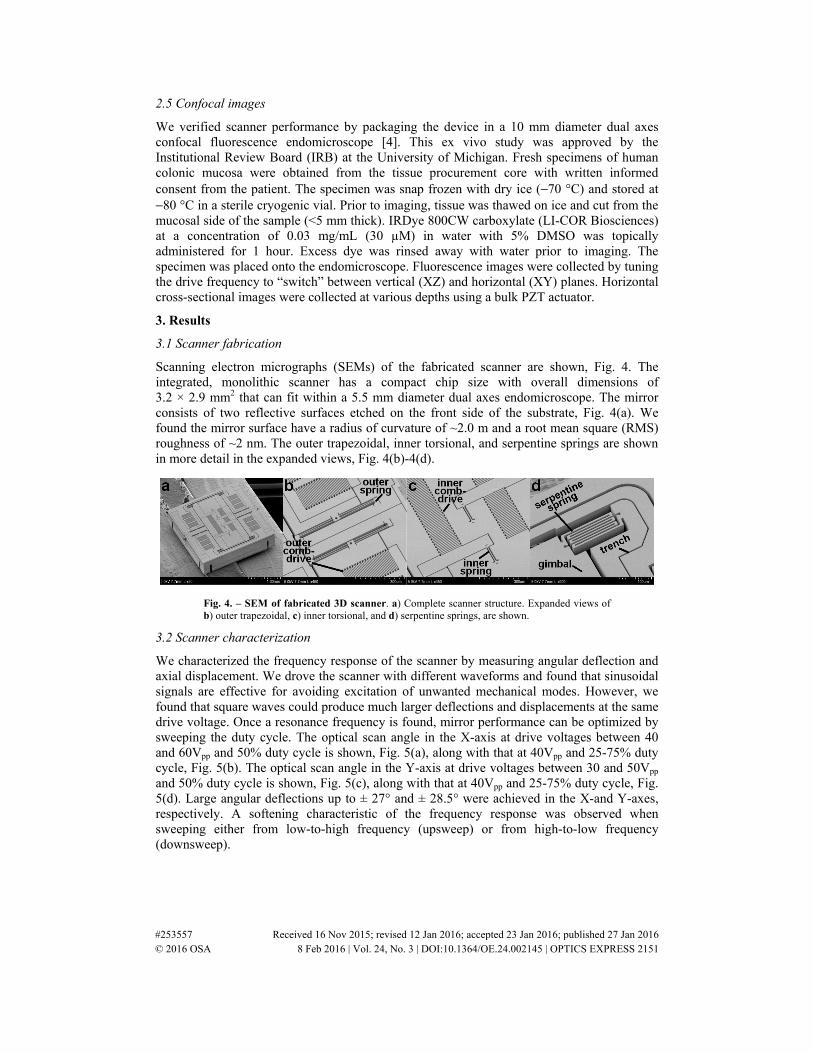
Scanning electron micrographs (SEMs) of the fabricated scanner are shown, Fig. 4. The integrated, monolithic scanner has a compact chip size with overall dimensions of 3.2 × 2.9 mm2 that can fit within a 5.5 mm diameter dual axes endomicroscope. The mirror consists of two reflective surfaces etched on the front side of the substrate, Fig. 4(a). We found the mirror surface have a radius of curvature of ~2.0 m and a root mean square (RMS) roughness of ~2 nm. The outer trapezoidal, inner torsional, and serpentine springs are shown in more detail in the expanded views, Fig. 4(b)-4(d).
Fig. 4. – SEM of fabricated 3D scanner. a) Complete scanner structure. Expanded views of b) outer trapezoidal, c) inner torsional, and d) serpentine springs, are shown.
3.2 Scanner characterization
We characterized the frequency response of the scanner by measuring angular deflection and axial displacement. We drove the scanner with different waveforms and found that sinusoidal signals are effective for avoiding excitation of unwanted mechanical modes. However, we found that square waves could produce much larger deflections and displacements at the same drive voltage. Once a resonance frequency is found, mirror performance can be optimized by sweeping the duty cycle. The optical scan angle in the X-axis at drive voltages between 40 and 60Vpp and 50% duty cycle is shown, Fig. 5(a), along with that at 40Vpp and 25-75% duty cycle, Fig. 5(b). The optical scan angle in the Y-axis at drive voltages between 30 and 50Vpp and 50% duty cycle is shown, Fig. 5(c), along with that at 40Vpp and 25-75% duty cycle, Fig. 5(d). Large angular deflections up to ± 27° and ± 28.5° were achieved in the X-and Y-axes, respectively. A softening characteristic of the frequency response was observed when sweeping either from low-to-high frequency (upsweep) or from high-to-low frequency (downsweep).
#253557 Received 16 Nov 2015; revised 12 Jan 2016; accepted 23 Jan 2016; published 27 Jan 2016 © 2016 OSA 8 Feb 2016 | Vol. 24, No. 3 | DOI:10.1364/OE.24.002145 | OPTICS EXPRESS 2151
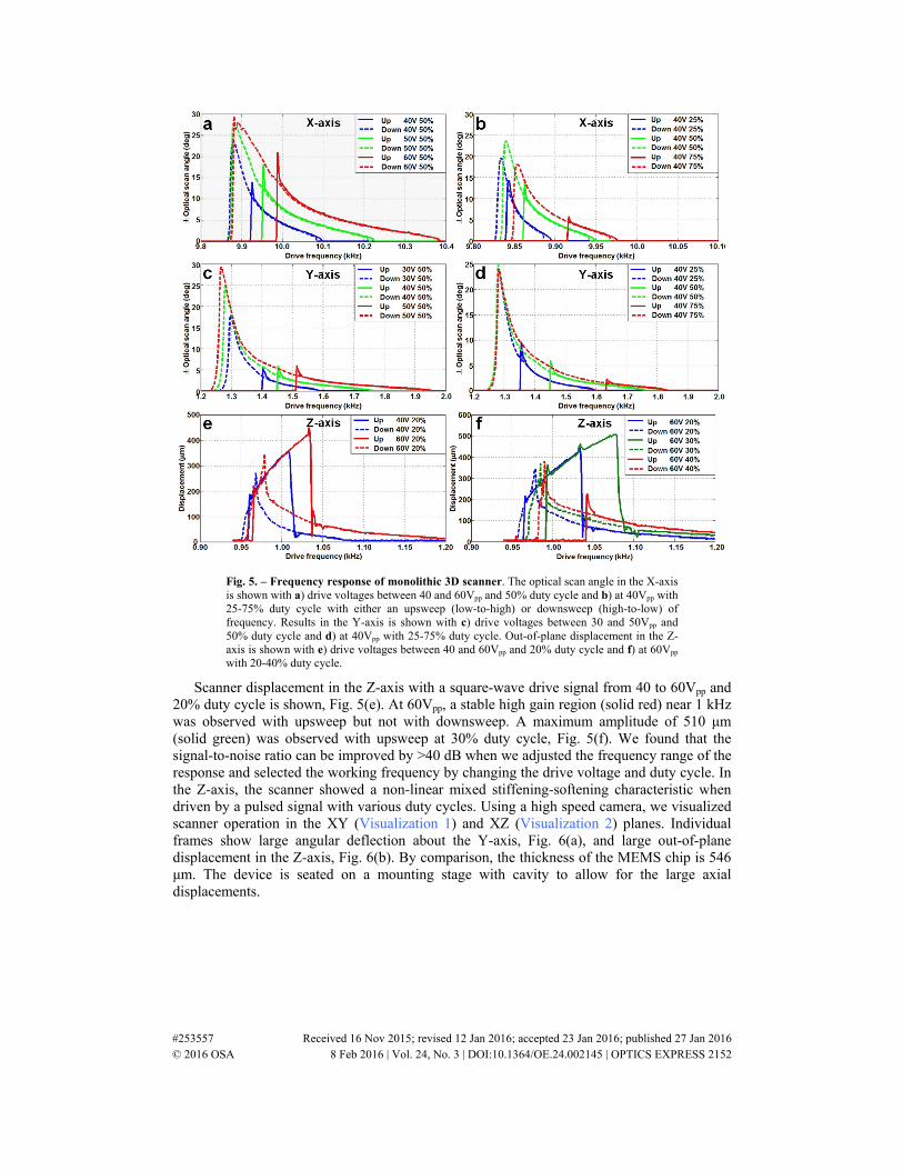
Fig. 5. – Frequency response of monolithic 3D scanner. The optical scan angle in the X-axis is shown with a) drive voltages between 40 and 60Vpp and 50% duty cycle and b) at 40Vpp with 25-75% duty cycle with either an upsweep (low-to-high) or downsweep (high-to-low) of frequency. Results in the Y-axis is shown with c) drive voltages between 30 and 50Vpp and 50% duty cycle and d) at 40Vpp with 25-75% duty cycle. Out-of-plane displacement in the Z-axis is shown with e) drive voltages between 40 and 60Vpp and 20% duty cycle and f) at 60Vpp with 20-40% duty cycle.
Scanner displacement in the Z-axis with a square-wave drive signal from 40 to 60Vpp and 20% duty cycle is shown, Fig. 5(e). At 60Vpp, a stable high gain region (solid red) near 1 kHz was observed with upsweep but not with downsweep. A maximum amplitude of 510 μm (solid green) was observed with upsweep at 30% duty cycle, Fig. 5(f). We found that the signal-to-noise ratio can be improved by >40 dB when we adjusted the frequency range of the response and selected the working frequency by changing the drive voltage and duty cycle. In the Z-axis, the scanner showed a non-linear mixed stiffening-softening characteristic when driven by a pulsed signal with various duty cycles. Using a high speed camera, we visualized scanner operation in the XY (Visualization 1) and XZ (Visualization 2) planes. Individual frames show large angular deflection about the Y-axis, Fig. 6(a), and large out-of-plane displacement in the Z-axis, Fig. 6(b). By comparison, the thickness of the MEMS chip is 546 μm. The device is seated on a mounting stage with cavity to allow for the large axial displacements.
#253557 Received 16 Nov 2015; revised 12 Jan 2016; accepted 23 Jan 2016; published 27 Jan 2016 © 2016 OSA 8 Feb 2016 | Vol. 24, No. 3 | DOI:10.1364/OE.24.002145 | OPTICS EXPRESS 2152
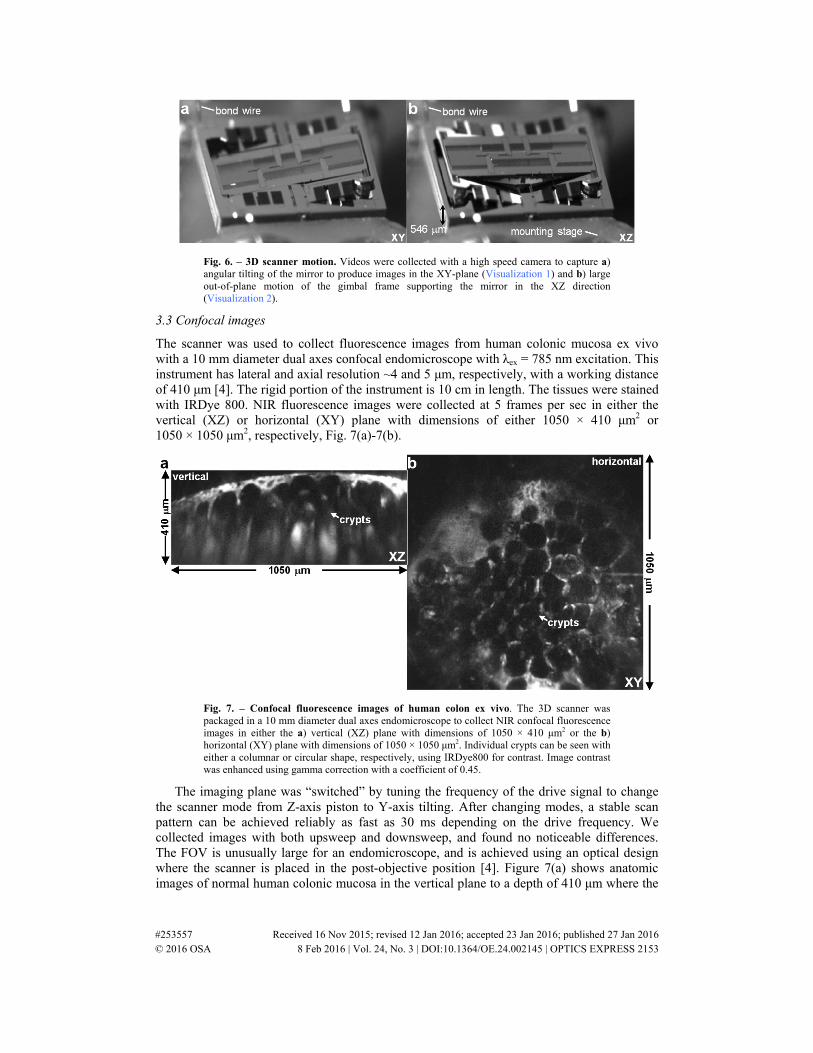
Fig. 6. – 3D scanner motion. Videos were collected with a high speed camera to capture a) angular tilting of the mirror to produce images in the XY-plane (Visualization 1) and b) large out-of-plane motion of the gimbal frame supporting the mirror in the XZ direction (Visualization 2).
3.3 Confocal images
The scanner was used to collect fluorescence images from human colonic mucosa ex vivo with a 10 mm diameter dual axes confocal endomicroscope with λex = 785 nm excitation. This instrument has lateral and axial resolution ~4 and 5 μm, respectively, with a working distance of 410 μm [4]. The rigid portion of the instrument is 10 cm in length. The tissues were stained with IRDye 800. NIR fluorescence images were collected at 5 frames per sec in either the vertical (XZ) or horizontal (XY) plane with dimensions of either 1050 × 410 μm2 or 1050 × 1050 μm2, respectively, Fig. 7(a)-7(b).
Fig. 7. – Confocal fluorescence images of human colon ex vivo. The 3D scanner was packaged in a 10 mm diameter dual axes endomicroscope to collect NIR confocal fluorescence images in either the a) vertical (XZ) plane with dimensions of 1050 × 410 μm2 or the b) horizontal (XY) plane with dimensions of 1050 × 1050 μm2. Individual crypts can be seen with either a columnar or circular shape, respectively, using IRDye800 for contrast. Image contrast was enhanced using gamma correction with a coefficient of 0.45.
The imaging plane was “switched” by tuning the frequency of the drive signal to change the scanner mode from Z-axis piston to Y-axis tilting. After changing modes, a stable scan pattern can be achieved reliably as fast as 30 ms depending on the drive frequency. We collected images with both upsweep and downsweep, and found no noticeable differences. The FOV is unusually large for an endomicroscope, and is achieved using an optical design where the scanner is placed in the post-objective position [4]. Figure 7(a) shows anatomic images of normal human colonic mucosa in the vertical plane to a depth of 410 μm where the
#253557 Received 16 Nov 2015; revised 12 Jan 2016; accepted 23 Jan 2016; published 27 Jan 2016 © 2016 OSA 8 Feb 2016 | Vol. 24, No. 3 | DOI:10.1364/OE.24.002145 | OPTICS EXPRESS 2153
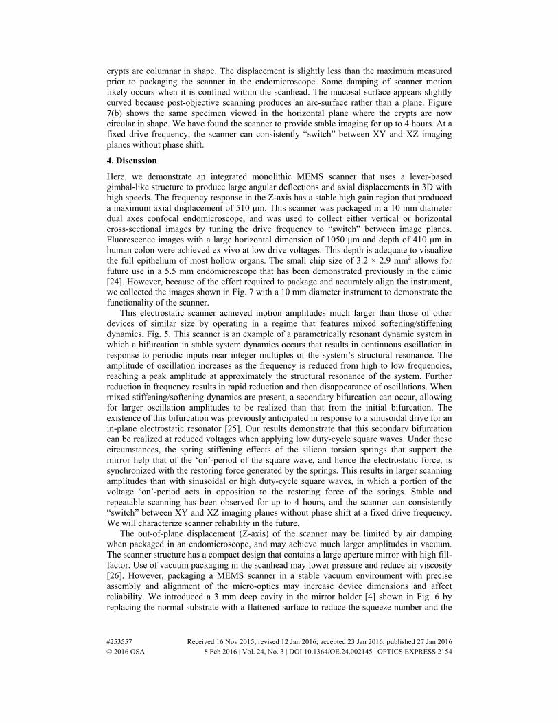
crypts are columnar in shape. The displacement is slightly less than the maximum measured prior to packaging the scanner in the endomicroscope. Some damping of scanner motion likely occurs when it is confined within the scanhead. The mucosal surface appears slightly curved because post-objective scanning produces an arc-surface rather than a plane. Figure 7(b) shows the same specimen viewed in the horizontal plane where the crypts are now circular in shape. We have found the scanner to provide stable imaging for up to 4 hours. At a fixed drive frequency, the scanner can consistently “switch” between XY and XZ imaging planes without phase shift.
4. Discussion
Here, we demonstrate an integrated monolithic MEMS scanner that uses a lever-based gimbal-like structure to produce large angular deflections and axial displacements in 3D with high speeds. The frequency response in the Z-axis has a stable high gain region that produced a maximum axial displacement of 510 μm. This scanner was packaged in a 10 mm diameter dual axes confocal endomicroscope, and was used to collect either vertical or horizontal cross-sectional images by tuning the drive frequency to “switch” between image planes. Fluorescence images with a large horizontal dimension of 1050 μm and depth of 410 μm in human colon were achieved ex vivo at low drive voltages. This depth is adequate to visualize the full epithelium of most hollow organs. The small chip size of 3.2 × 2.9 mm2 allows for future use in a 5.5 mm endomicroscope that has been demonstrated previously in the clinic [24]. However, because of the effort required to package and accurately align the instrument, we collected the images shown in Fig. 7 with a 10 mm diameter instrument to demonstrate the functionality of the scanner.
This electrostatic scanner achieved motion amplitudes much larger than those of other devices of similar size by operating in a regime that features mixed softening/stiffening dynamics, Fig. 5. This scanner is an example of a parametrically resonant dynamic system in which a bifurcation in stable system dynamics occurs that results in continuous oscillation in response to periodic inputs near integer multiples of the system’s structural resonance. The amplitude of oscillation increases as the frequency is reduced from high to low frequencies, reaching a peak amplitude at approximately the structural resonance of the system. Further reduction in frequency results in rapid reduction and then disappearance of oscillations. When mixed stiffening/softening dynamics are present, a secondary bifurcation can occur, allowing for larger oscillation amplitudes to be realized than that from the initial bifurcation. The existence of this bifurcation was previously anticipated in response to a sinusoidal drive for an in-plane electrostatic resonator [25]. Our results demonstrate that this secondary bifurcation can be realized at reduced voltages when applying low duty-cycle square waves. Under these circumstances, the spring stiffening effects of the silicon torsion springs that support the mirror help that of the ‘on’-period of the square wave, and hence the electrostatic force, is synchronized with the restoring force generated by the springs. This results in larger scanning amplitudes than with sinusoidal or high duty-cycle square waves, in which a portion of the voltage ‘on’-period acts in opposition to the restoring force of the springs. Stable and repeatable scanning has been observed for up to 4 hours, and the scanner can consistently “switch” between XY and XZ imaging planes without phase shift at a fixed drive frequency. We will characterize scanner reliability in the future.
The out-of-plane displacement (Z-axis) of the scanner may be limited by air damping when packaged in an endomicroscope, and may achieve much larger amplitudes in vacuum. The scanner structure has a compact design that contains a large aperture mirror with high fill-factor. Use of vacuum packaging in the scanhead may lower pressure and reduce air viscosity [26]. However, packaging a MEMS scanner in a stable vacuum environment with precise assembly and alignment of the micro-optics may increase device dimensions and affect reliability. We introduced a 3 mm deep cavity in the mirror holder [4] shown in Fig. 6 by replacing the normal substrate with a flattened surface to reduce the squeeze number and the
#253557 Received 16 Nov 2015; revised 12 Jan 2016; accepted 23 Jan 2016; published 27 Jan 2016 © 2016 OSA 8 Feb 2016 | Vol. 24, No. 3 | DOI:10.1364/OE.24.002145 | OPTICS EXPRESS 2154
coefficient of viscous damping (or torque) of the squeeze film damping to achieve the large axial displacement with high scan speeds. This packaging strategy allows the compliant lever mechanism on the mirror gimbal to achieve unusually large stroke lengths for an electrostatic MEMS scanner at high scan speeds and in ambient pressure.
5. Summary
We show the design, fabrication, and performance of a compact integrated monolithic 3D MEMS scanner with dimensions of 3.2 × 2.9 mm2 that produces large angular deflections and out-of-plane displacement. Optical deflection angles up to ± 27° and ± 28.5° in the X- and Y-axes and up to 510 μm in the Z-axis were achieved with low drive voltages at atmospheric pressure. When packaged in a dual axes confocal endomicroscope, vertical and horizontal cross-sectional images can be collected seamlessly in tissue with large FOV at 5 frames/sec. In the future, this device may be used as an adjunct to medical endoscopes to perform instantaneous histology in vivo.
Acknowledgments
Funding provided in part by National Cancer Institutes R01 CA142750 (TDW, KK), U54 CA13642 (TDW), R01 EB020644 (KRO), and Mary L. Petrovich. We thank Steve Donajkowski from the instrument shop for discussion and fabrication of instrument packaging.
s
#253557 Received 16 Nov 2015; revised 12 Jan 2016; accepted 23 Jan 2016; published 27 Jan 2016 © 2016 OSA 8 Feb 2016 | Vol. 24, No. 3 | DOI:10.1364/OE.24.002145 | OPTICS EXPRESS 2155