integrated heat pump (ihp) system development · integrated heat pump (ihp) system development ......
TRANSCRIPT

ORNL/TM-2006/143
Integrated Heat Pump (IHP) System Development Air-Source IHP Control Strategy and Specification and Ground-Source IHP Conceptual Design
May 2007 Prepared by R. W. Murphy, C. K. Rice, and V. D. Baxter

DOCUMENT AVAILABILITY Reports produced after January 1, 1996, are generally available free via the U.S. Department of Energy (DOE) Information Bridge. Web site http://www.osti.gov/bridge Reports produced before January 1, 1996, may be purchased by members of the public from the following source. National Technical Information Service 5285 Port Royal Road Springfield, VA 22161 Telephone 703-605-6000 (1-800-553-6847) TDD 703-487-4639 Fax 703-605-6900 E-mail [email protected] Web site http://www.ntis.gov/support/ordernowabout.htm Reports are available to DOE employees, DOE contractors, Energy Technology Data Exchange (ETDE) representatives, and International Nuclear Information System (INIS) representatives from the following source. Office of Scientific and Technical Information P.O. Box 62 Oak Ridge, TN 37831 Telephone 865-576-8401 Fax 865-576-5728 E-mail [email protected] Web site http://www.osti.gov/contact.html
This report was prepared as an account of work sponsored by an agency of the United States Government. Neither the United States Government nor any agency thereof, nor any of their employees, makes any warranty, express or implied, or assumes any legal liability or responsibility for the accuracy, completeness, or usefulness of any information, apparatus, product, or process disclosed, or represents that its use would not infringe privately owned rights. Reference herein to any specific commercial product, process, or service by trade name, trademark, manufacturer, or otherwise, does not necessarily constitute or imply its endorsement, recommendation, or favoring by the United States Government or any agency thereof. The views and opinions of authors expressed herein do not necessarily state or reflect those of the United States Government or any agency thereof.

ORNL/TM-2006/143
Engineering Science and Technology Division
INTEGRATED HEAT PUMP (IHP) SYSTEM DEVELOPMENT
Air-Source IHP Control Strategy and Specification and Ground-Source IHP Conceptual Design
— FY06 Milestone Report —
R. W. Murphy C. K. Rice
V. D. Baxter
May 2007
Prepared by OAK RIDGE NATIONAL LABORATORY
Oak Ridge, Tennessee 37831-6283 managed by
UT-BATTELLE, LLC for the
U.S. DEPARTMENT OF ENERGY under contract DE-AC05-00OR22725


i
CONTENTS
Abstract .......................................................................................................................................... iii 1. OVERVIEW............................................................................................................................... 1 2. INTRODUCTION — THE INTEGRATED HEAT PUMP CONCEPT ................................... 1
2.1 Prior Experience................................................................................................................. 1 2.2 DOE–ORNL Approach...................................................................................................... 2
3. AIR-SOURCE IHP CONTROL STRATEGY........................................................................... 4 3.1 Primary Functions.............................................................................................................. 4 3.2 System Components and Control Types............................................................................ 4 3.3 Operational Strategy .......................................................................................................... 6 3.4 Inputs to the Control System.............................................................................................. 6 3.5 Operating Modes................................................................................................................ 7
3.5.1 Space Cooling (AC) ................................................................................................. 8 3.5.2 Space Cooling With Enhanced Dehumidification (ACEAD) .................................. 8 3.5.3 Space Cooling Plus “On Demand” Water Heating (ACWH)................................... 9 3.5.4 Space Cooling With Enhanced Dehumidification plus “On Demand” Water
Heating (ACEADWH).......................................................................................... 10 3.5.5 Space Heating (AH) ............................................................................................... 10 3.5.6 Space Heating plus “on demand” Water Heating (AHWH)................................... 11 3.5.7 Demand Water Heating (WH)................................................................................ 12 3.5.8 Dehumidification (AD) .......................................................................................... 12 3.5.9 Space Dehumidification Plus Water Heating (ADWH) ......................................... 13 3.5.10 Ventilation (AV)................................................................................................... 14 3.5.11 Ventilation With Ventilation Air Dehumidification (AVVAD)........................... 14 3.5.12 Ventilation Plus Water Heating (AVWH)............................................................ 14 3.5.13 Outdoor Coil Defrosting (OCD)........................................................................... 15
3.6 Speed Control Relationships and AS-IHP Performance for Selected Operating Modes . 16 3.6.1 Compressor Speed Ratio vs. Ambient in Cooling and Heating Modes.................. 17 3.6.2 Control Parameters vs. Compressor Speed Ratio in the Space Cooling and Heating
Modes.................................................................................................................... 18 3.6.3 Target Speed Ratios and Refrigerant Flow Control vs. Ambient in Space Cooling
and Heating Modes ............................................................................................... 20 3.6.4 Target Compressor Speed Ratios For Space Heating, Space Cooling, Water
Heating, and Ventilation Cooling Modes vs. Ambient ......................................... 21 3.6.5 Target Air-Source IHP Space Heating and Cooling Performance vs. Ambient With
Proposed Control Relationships for Load Tracking.............................................. 22 3.6.6 Target Air-Source IHP Water Heating Performance vs. Ambient With Proposed
Control Relationships............................................................................................ 23 3.6.7 Target Air-Source IHP Ventilation Cooling Performance vs. Ambient With
Proposed Control Relationships............................................................................ 24 3.6.8 Target Air-Source IHP Ventilation Cooling Sensible Heat Ratio (SHR) vs.
Ambient With Proposed Control Relationships.................................................... 26 3.7 Other Possible Control Options or Approaches for Further Consideration ..................... 26
3.7.1 Option for Outside Air Economizer Mode............................................................. 26 3.7.2 Alternative Approach to Providing Dedicated Dehumidification Mode................ 26
4. AS-IHP SYSTEM SPECIFICATIONS.................................................................................... 27 4.1 Refrigerant Compressor ................................................................................................... 28

ii
4.2 Indoor Fan/Blower ........................................................................................................... 28 4.3 Outdoor Fan ..................................................................................................................... 28 4.4 Refrigerant-to-Water HX ................................................................................................. 28 4.5 Water-to-Air HX.............................................................................................................. 28 4.6 Indoor Refrigerant-to-Air HX.......................................................................................... 29 4.7 Outdoor Refrigerant-to-Air HX ....................................................................................... 29 4.8 Electrical Resistance Water Heating Elements ................................................................ 29 4.9 Water Pump ..................................................................................................................... 29 4.10 Hot Water Storage Tank ................................................................................................ 29
5. CONCEPTUAL DESIGN FOR GROUND-SOURCE IHP..................................................... 29 5.1 GS-IHP Equipment Concept............................................................................................ 32 5.2 Ground-Source HX Options ............................................................................................ 33 5.3 Operational Control Concept ........................................................................................... 34 5.4 Plan for Further Development of GS-IHP Concept ......................................................... 35
6. REFERENCES......................................................................................................................... 35

iii
ABSTRACT
The integrated heat pump (IHP), as one appliance, can provide space cooling, heating, ventilation, and dehumidification while maintaining comfort and meeting domestic water heating needs in near-zero-energy home (NZEH) applications. In FY 2006 Oak Ridge National Laboratory (ORNL) completed development of a control strategy and system specification for an air-source IHP. The conceptual design of a ground-source IHP was also completed. Testing and analysis confirm the potential of both IHP concepts to meet NZEH energy services needs while consuming 50% less energy than a suite of equipment that meets current minimum efficiency requirements.
This report is in fulfillment of an FY06 DOE Building Technologies (BT) Joule Milestone.

iv

1
1. OVERVIEW
The approach to near-zero-energy housing (NZEH) places new demands on heating, ventilating, air-conditioning (HVAC), and water heating equipment. First, the HVAC system generally needs to be smaller in size (capacity) than is customary in today’s homes. Analyses are converging on about 1-1/4 tons as the approximate size needed to meet the reduced heating and cooling load of an 1800-ft2 NZEH in an Atlanta location. Second, as buildings become tighter, there is much less natural infiltration, and a larger portion of the HVAC load is due to ventilation needed to provide fresh air on a controlled basis. Moreover, bringing moist ventilation air to space-neutral conditions increases the need for increased latent cooling. And third, although the space conditioning loads are smaller with a tighter building envelope, the water heating load, which depends largely on the number of occupants in the dwelling, remains essentially unchanged. Consequently, the water heating load becomes a larger portion of the overall heating and cooling demands to be met by building equipment in the house.
The need for continuous mechanical ventilation combined with a smaller capacity HVAC system and unchanged hot water demand suggests that a single, load-following, integrated system — the integrated heat pump (IHP) — would be a good match to an NZEH’s needs for space conditioning, ventilation, dehumidification, and water heating. This conclusion is based on the demonstrated efficiency of vapor compression technology.
Equipment with the capability for load following and the ability to control supply air sensible heat ratios (SHR) typically falls into the variable-speed category. Load following provides improved space temperature and humidity control, and that improves comfort. Load following also provides long (continuous) equipment and fan runtimes, which is a duty cycle well suited to conditions of continuous flow of ventilation air and for the efficient production of domestic hot water using heat pumping and heat recovery in the cooling season. The more continuous air movement with variable-capacity systems also improves occupants’ comfort.
Variable-speed technologies are growing in use and in efficiency. A recent newsletter from the International Institute of Refrigeration (July 2005) notes that many Japanese HVAC equipment manufacturers are shifting more of their production to variable-refrigerant-flow systems based on inverter drives and variable-speed technologies. As the volume of this mass production continues to increase, the relative cost of variable-speed drive and motor technology will continue to drop, as have costs for most electronic components for equipment, especially in the lower power rating sizes being considered here and for the production volumes in Asian markets. The remaining cost premium associated with variable-speed technology, although shrinking, can be significantly offset through HVAC designs that apply variable-speed technologies to perform the additional functions of dehumidification and water heating — all of growing concern in the path to NZEH.
2. INTRODUCTION — THE INTEGRATED HEAT PUMP CONCEPT
2.1 Prior Experience
Prior efforts have been made to develop and commercialize an IHP. Notable was the work by the Electric Power Research Institute (EPRI) and the Carrier Corporation on the HydroTech 2000, a residential system with five modes of operation including dedicated water heating. This system was offered in 2- and 3-ton nominal cooling capacities with Air-Conditioning and Refrigeration Institute (ARI) certified ratings of 13.35 to 14.05 SEER (seasonal energy efficiency ratio) and

2
8.75 to 9.05 HSPF (heating season performance factor). Separate ventilation and dedicated dehumidification modes were not incorporated, as the work preceded the current interest in NZEH. A two-year field study of this unit conducted by the National Institute of Science and Technology (NIST) (Fanney 1993) showed that the combined performance factor was 2.45. The performance factor was defined as the quotient of all of the space conditioning and water heating loads and the total amount of electrical energy needed to meet them. Production of the unit was halted within two years of its introduction. Total sales amounted to a few hundred units.
A more recent effort was Nordyne’s PowerMiser, which was initially offered as a 3-ton unit, then as a 5-ton unit. Production was halted after several years on the market and total sales of a few thousand units. Both the HydroTech and PowerMiser were split systems with three components: an outdoor fan coil unit, an indoor unit (similar to a conventional split system air-source heat pump), and another indoor unit that contained the compressor, refrigerant-to-water heat exchanger (HX), water pump, and controls.
2.2 DOE–ORNL Approach
With the support of the U.S. Department of Energy (DOE), ORNL has been working to develop an IHP system that provides space conditioning and produces domestic hot water efficiently (Tomlinson 2005). It is intended to address the energy service needs of homes which are characterized by tighter, better-insulated envelopes like NZEH’s, as well as smaller dwelling units on the market today. In addition to providing space heating and cooling like a conventional heat pump, the IHP uses heat pumping to provide hot water, and also has operating modes for dedicated dehumidification and ventilation.
The IHP is unique in several ways: 1. A small capacity (nominally 1-1/4-ton cooling mode) suited for low-energy-consuming
buildings that approach the NZEH goal 2. Operating modes that treat (to space-neutral temperature and humidity) the ventilation
air needed to supply fresh outside air to the building and provide dehumidification on demand for improved thermal comfort in tight building designs
3. Operating modes that produce domestic hot water using efficient heat pumping 4. A very high system efficiency level due to full modulation of the capacity of the
system to meet energy service needs according to thermal demand (load-matching operation that improves space comfort conditions)
Both air-source and ground-source versions of the IHP concept are being actively investigated.
The ORNL design is based on prior analyses of options for an IHP. The concept under investigation shown in figures 1 and 2 for space heating and space cooling operation, respectively, uses several modulating components including a modulating compressor, one multiple-speed pump, two variable-speed fans, and heat exchangers — two air-to-refrigerant, one water-to-refrigerant, and one air-to-water — to meet all the HVAC and water heating loads. The air-to-water HX uses excess hot water generated in the cooling and the dehumidification modes to temper the ventilation air, as needed, for space-neutral conditions. Compressor or indoor fan speed and water pump speed control are used to control both humidity levels and indoor temperature, when needed. Note that water heating and air tempering can be done at the same time.

3
Fig. 1. Air-source IHP concept schematic, space heating mode shown.
Fig. 2. Air-source IHP concept schematic, space cooling mode shown.
In FY06 we completed development of an initial control strategy and component specifications for a fully functioning air-source (AS) IHP prototype. We also completed a conceptual design for the ground-source (GS) IHP option. The following sections describe these developments. A companion business case assessment (Baxter 2007) indicated good potential for the IHP to provide for energy service needs at efficiency levels sought by DOE for an 1800-ft2 NZEH in five different locations without negative cost implications (in terms of the total cost of energy and mortgage, or “total owning cost”). Among the conclusions from that study is that an IHP-equipped NZEH can be significantly less costly than an NZEH using current HVAC and water heating technology. While the IHP technology is being developed with the NZEH application in mind, there are more immediate opportunities for its use. Currently built new homes having separate HVAC units for first and second floors represent immediate market opportunities for

4
IHP systems to satisfy the NZEH-like first floor space conditioning loads while meeting the water heating, demand dehumidification, and ventilation loads as well. Increased numbers of smaller single-level retirement condominiums are expected to be built in the near future as well. These applications can provide a large near-term market opportunity for air-source or ground-source IHP systems.
Pending a favorable decision by DOE–BT, further development of both IHP concepts is planned for FY07. For the AS-IHP, effort will focus on converting the existing manually operated steady-state breadboard into a functional prototype based on the control strategy and system specifications outlined in this report. We will test the preferred control strategy suggested by analysis, investigate refinements as resources permit, and update estimates of cost and performance potential, which will be integrated into an updated business case assessment. Performance of the prototype AS-IHP will be evaluated against the Gate 4 criteria for transition from Stage 3, Advanced Development, to Stage 4, Engineering Development. Pending a positive outcome and favorable decision by DOE–BT, detailed specifications will be prepared to support a competitive procurement by the National Energy Technology Laboratory to select an original equipment manufacturer to produce the first prototype units for field testing. For the GS-IHP, development and testing of a manually operated laboratory breadboard prototype based on the FY06 conceptual design will be initiated. The GS-IHP will be evaluated against the Gate 3 criteria for transition from Stage 2, Exploratory Development, to Stage 3, Advanced Development.
3. AIR-SOURCE IHP CONTROL STRATEGY
3.1 Primary Functions
The integrated heat pump is a single system intended to perform a variety of energy-related functions with efficiencies targeted to meet requirements for a NZEH of the future. The primary functions include
• space heating, • space cooling, • dehumidifying, • air ventilating, and • water heating.
3.2 System Components and Control Types
To accomplish these functions, various components must be combined to form the system. To achieve the desired capacities and efficiencies, they must be connected in an appropriate arrangement and controlled effectively. The approach builds, where possible, on methods employed in previous industry attempts to market air-source integrated systems, including the EPRI/Carrier HydroTech 2000 and the EPRI/Nordyne Powermiser models (U.S. Patents 1991a, 1991b, 1991c, 1992, 1993, and 1997; Carrier 1989a, 1989b, and 1989c; Nordyne). Priority is given to heat pumping system operation in order to provide the needed home energy services as efficiently as possible. Only when heat pumping operation is unable to fully meet these needs is use made of less efficient secondary systems.
For the AS-IHP, the major energy-consuming components for heat pumping are shown in Table 1. Minor energy-consuming components are shown in Table 2.

5
Table 1. Major energy-consuming components for heat pumping
Component Control type Refrigerant compressor On/off, variable-speed Indoor fan On/off, variable-speed Outdoor fan On/off, variable-speed Water pump On/off, multiple-speed
Table 2. Minor energy-consuming components for heat pumping
Component Control type Thermostat Mode, time, temperature, humidity Microprocessor(s) Input/output Refrigerant reversing valve actuator Biposition (cooling or heating) Electronic refrigerant expansion valve actuator(s) Variable position (opening) Heating water valve actuator Biposition (open or closed) Tempering water valve actuator Variable position (opening) Return air damper actuator Biposition (open or closed) Ventilation air damper actuator Biposition (open or closed)
Sizing of the system is such that, barring component failure, heat pumping should provide adequate capacity for the space cooling, dehumidifying, and ventilation steady-state loads in the design house. The only loads likely to exceed temporarily the heat pumping system capabilities would be space heating and/or water heating under more extreme conditions (low outdoor temperatures and/or concentrated hot water usage). For these short-duration situations, (substantially less efficient) secondary energy-consuming components shown in Table 3 would be activated.
Table 3. Secondary energy-consuming components
Component Control type Electrical resistance air heating element (indoor air handler)
On/off
Electrical resistance water heating element (upper, hot water storage tank)
On/off
Electrical resistance water heating element (lower, hot water storage tank)
On/off
Crucial to achieving the required performance is the incorporation of efficient variable-speed and/or multiple-speed operation over wide ranges in the major energy consuming components. The compressor and fans are essentially continuously variable over their entire ranges. The water pump motor has three discrete speeds. Thus, for each of these components, the control system must determine, for given conditions, whether the component should be on or off and, if on, how fast it should be running. For refrigerant expansion and water tempering control valves, the appropriate variable opening needs to be set per calls and conditions to provide the desired control condition, such as prescribed values of condenser subcooling, liquid tube temperature, or supply air temperature.

6
3.3 Operational Strategy
The general intent for the variable- and multiple-speed components is to optimize their speeds for any particular combination of loads so as to provide required capacities at maximum system efficiency. The reduction in HX loadings to just meet the current conditioning loads is the major contribution to higher system efficiency. Also inherent in the strategy is reducing system cycling losses by maximizing run times of the highly efficient components. Generally this implies operation at the lowest speeds that will meet the load requirements. Of course, this must be accomplished within the established performance envelope of each component. For example, in addition to the usual discharge temperature limit for a single-speed compressor, there are generally additional restrictions for a variable-speed compressor such as limits for suction pressure, discharge pressure, and compression ratio that vary for each speed range. In addition, there will likely be limits on ramp (increasing or decreasing) rates when speeds are to be changed.
Other variable components, such as expansion valves, will be controlled over their available ranges to accommodate the desired capacities for selected modes. The remaining components require only binary decisions from the control system. In particular, the refrigerant reversing valve is either in the “cooling” position or the “heating” position; the water circuit valves are arranged so that water flows through the refrigerant-to-water HX, the water-to-air tempering HX, or both; the return and ventilation air dampers are either open or closed; the air-heating electrical resistance elements are either on or off; and the water-heating electrical resistance elements are either on or off (upper and lower elements are not permitted to operate simultaneously).
The ASHRAE 62.2 (2004) requirement as applied to the candidate NZEH implies an average calculated air flow from the outdoors to the indoors. The intent of the control strategy is to use the system indoor fan to induce this amount of ventilation air flow while the system functions in nearly all the cooling, heating, and dehumidification control modes. When the system does not operate in one of these modes, a ventilation/flow timer will activate the indoor fan to induce about three times the calculated flow for 20 minutes of each hour in a ventilation operating mode to meet the requirement, while maintaining adequate air distribution uniformity.
3.4 Inputs to the Control System
To decide which components to turn on or off and at what speed or position, the control system requires various inputs (Table 4). Some are occupant-selected and some are inputs gathered from various sensors and clocks or timers. The most familiar occupant-selected inputs are fan mode and heating/cooling or season selections at the thermostat. Other common occupant inputs are the air temperature and air humidity set points at the thermostat, as well as time-related options such as day or night setback/setup settings. Common air sensor inputs for space conditioning are thermostat humidity and air temperatures at the thermostat, in the supply from the indoor air handler, and in the outdoor ambient air. Various refrigerant line temperatures including compressor discharge, accumulator suction, indoor liquid tube, and outdoor liquid tube are also employed. For water heating purposes, two additional temperature sensor inputs are normally employed: one near the bottom of the water storage tank and one in the upper section of the water storage tank. Other temperature sensors on the refrigerant-to-air heat exchangers may also be required for optimum control. Selected clock and timer inputs are also generally incorporated.

7
Table 4. Control inputs and sources
Input Source Fan mode Occupant-selected at thermostat Heating/cooling or season selection Occupant-selected at thermostat Thermostat air temperature setting Occupant-selected at thermostat Thermostat air humidity setting Occupant-selected at thermostat Time-related options (setback, etc.) Occupant-selected at thermostat Thermostat air humidity Sensor in thermostat Thermostat air temperature Sensor in thermostat Supply air temperature Sensor in indoor air handler section Ambient air temperature Sensor in outdoor air handler section Compressor refrigerant discharge temperature Sensor in compressor section Accumulator refrigerant suction temperature Sensor in compressor section Indoor refrigerant liquid tube temperature Sensor in indoor air handler section Outdoor refrigerant liquid tube temperature Sensor in outdoor air handler section Upper tank water temperature Sensor on upper water storage tank Bottom tank water temperature Sensor on bottom hot water storage tank Indoor mid-coil temperature Sensor in indoor air handler section Outdoor mid-coil temperature Sensor in outdoor air handler section Indoor coil exit temperature Sensor in indoor air handler section Outdoor coil exit temperature Sensor in outdoor air handler section Clock Ventilation timer Indoor fan delay Compressor restart timer Defrost timer
3.5 Operating Modes
Microprocessors will determine the operating mode of the system based on load demands indicated by the various inputs. The load demands may be for space cooling or heating, water heating, dehumidification, ventilation, outdoor coil defrosting, or selected combinations of these. The available primary system operating modes corresponding to the loads are:
• space cooling (AC), • space cooling with enhanced dehumidification (ACEAD), • space cooling with enhanced space dehumidification plus water heating (ACEADWH), • space heating (AH), • space heating plus water heating (AHWH), • water heating (WH), • dehumidification (AD), • dehumidification plus water heating (ADWH), • ventilation (AV), • ventilation with ventilation air dehumidification (AVVAD), • ventilation plus water heating (AVWH), and

8
• outdoor coil defrosting (OCD).
The particular mode decision determines which components will operate (Table 5) and how they will be controlled. A description of the logic employed by the system for each primary mode follows.
Table 5. Mode/component matrix
Mode Component
Compre
ssor
Refrigerant reversing
valve Outdoor
fan Indoor
fan
Air return
damper
Air ventilation
damper Water pump
Water heating valve
Water tempering
valve
Air resistance element
water resistance elements
AC on cool on on open open ACEAD on cool on on open open ACWH on cool on open open on open either ACEADWH on cool on open open on open either AH on heat on on open open either AHWH on heat on on open open on open either either WH on heat on on open either AD on cool on on open open on open ADWH on cool on open open on open open either AV on open open AVVAD on cool on on open on open AVWH on heat on on open open on open either OCD on cool on open either
3.5.1 Space Cooling (AC)
When the space air temperature exceeds the thermostat cooling temperature set point, a space cooling load is indicated. In the absence of other indicated loads, the refrigerant reversing valve is situated in the cooling position, the return and ventilation air dampers are open, and the heat pump system provides air cooling in proportion to the load by varying the compressor speed (within the permissible envelope) at the rate needed to stay within the thermostat temperature deadband. The coincident indoor and outdoor fan speeds are adjusted in a prescribed manner based on the compressor speed. Heat removed from the indoor air and energy input by the compressor is rejected to the outdoor air. The water-to-refrigerant HX is active at low pump speed if beneficial water heating can be provided by the desuperheating function. When in desuperheating mode, it is recommended that water be allowed to exceed the nominal water heater set point of 120°F up to some specified maximum upper tank temperature of 140 to 150°F to take maximum advantage of heat recovery opportunities.
3.5.2 Space Cooling with Enhanced Dehumidification (ACEAD)
When (1) the space air temperature exceeds the thermostat cooling temperature set point and (2) the space relative humidity exceeds the thermostat humidity set point, both air cooling and dehumidification loads are indicated. In the absence of other indicated loads, the reversing valve is situated in the cooling position, the return and ventilation air dampers are open, and, as in the previous case, the heat pump system provides air cooling in proportion to the load by varying the compressor, indoor fan, and outdoor fan speeds. However, in this case, the air moisture removal rate is increased by reducing the indoor fan speed relative to the compressor speed.

9
The goal is to increase latent cooling capacity by setting the compressor and fan speeds so as to satisfy the sensible cooling load with a lowered indoor coil temperature to increase dehumidification. Heat removed from the indoor air and energy input by the compressor is rejected to the outdoor air. If the dehumidification load requirement is met before the space cooling load requirement, the control system transitions to the space cooling mode. If the space cooling load requirement is met before the dehumidification mode requirement, the control system transitions to the dehumidification mode. The water-to-refrigerant HX is active at low pump speed if beneficial water heating can be provided by the desuperheating function.
3.5.3 Space Cooling plus “on demand” Water Heating (ACWH)
When (1) the space air temperature exceeds the thermostat cooling temperature set point and (2) the lower water storage tank temperature is below its set point, both space cooling and water heating loads are indicated. In the absence of other indicated loads, as shown in Fig. 3, the reversing valve is situated in the cooling position, the return and ventilation air dampers are open, the water valve to the refrigerant-to-water HX circuit is open, the water pump is activated, and the heat pump system provides air cooling in proportion to the air cooling load by varying the compressor and indoor fan speeds.
Fig. 3. Space cooling plus “on demand” water heating (ACWH).

10
In this mode, the outdoor fan is not active, so that the majority of the combined heat removed from the indoor air and energy input to the refrigerant from the compressor is transferred to the circulating water (in the refrigerant-to-water HX). The remainder of the heat is rejected by natural convection processes in the refrigerant line set and the outdoor refrigerant-to-air HX. If the water heating load requirement is met before the space cooling load requirement, the control system transitions to the space cooling mode. If the space cooling load requirement is met before the water heating mode requirement, the control system transitions to the water heating mode.
When (1) the lower water storage tank temperature is below its set point and (2) the upper water storage tank temperature is below its set point, a critical water heating load is indicated. In this situation, the control system activates the upper electrical resistance element to minimize the chance of running out of hot water.
3.5.4 Space Cooling with Enhanced Dehumidification plus “On Demand” Water Heating (ACEADWH)
When (1) the space air temperature exceeds the thermostat cooling temperature set point, (2) the space relative humidity exceeds the thermostat humidity set point, and (3) the lower water storage tank temperature is below its set point, three loads are indicated: space cooling, dehumidification, and water heating. In the absence of other indicated loads, the reversing valve is situated in the cooling position, the return and ventilation air dampers are open, the water valve to the refrigerant-to-water HX circuit is open, the water pump is activated, and the heat pump system provides air cooling in proportion to the space cooling load by varying the compressor and indoor fan speeds.
In this case, the air moisture removal rate is increased by reducing the indoor fan speed relative to the compressor speed. As before, the goal is to increase latent cooling capacity by setting the compressor and fan speeds so as to satisfy the sensible cooling load with a lowered indoor coil temperature to increase dehumidification. Also in this mode, the outdoor fan is not active, so that the majority of the combined heat removed from the house and energy input to the refrigerant from the compressor is transferred to the circulating water (in the refrigerant-to-water HX). The remainder of the heat is rejected by natural convection processes in the refrigerant line set and the outdoor refrigerant-to-air HX. If the dehumidification load requirement is met first, the control system transitions to the space cooling plus water heating mode. If the air cooling load requirement is met first, the control system transitions to the dehumidification plus water heating mode. If the water heating load requirement is met first, the control system transitions to the air cooling with enhanced dehumidification mode.
When (1) the lower water storage tank temperature is below its set point and (2) the upper water storage tank temperature is below its set point, a critical water heating load is indicated. In this situation, the control system activates the upper electrical resistance element to minimize the chance of hot water running out.
3.5.5 Space Heating (AH)
When the space air temperature is below the thermostat heating temperature set point, a space heating load is indicated. In the absence of other indicated loads, the reversing valve is situated in the heating position, the return and ventilation air dampers are open, and the heat pump system provides space heating in proportion to the load by appropriately varying the compressor, indoor fan, and outdoor fan speeds. The control logic varies the compressor and outdoor fan speeds to meet the space heating load at highest efficiency while the indoor speed is varied to maintain comfortable supply air temperatures. Heat removed from the outdoor air and energy input by the

11
compressor is provided to the indoor air. If the space heating load exceeds the heat pump capacity, the control system activates the electrical resistance air heaters in the indoor unit. At outdoor temperatures below a specified minimum, the compressor is locked out and the total space heating load is met using auxiliary resistive heating. The water-to-refrigerant HX is active at low pump speed if beneficial water heating can be provided by the desuperheating function.
3.5.6 Space Heating plus “on demand” Water Heating (AHWH)
When (1) the space air temperature is below the thermostat heating temperature set point and (2) the lower water storage tank temperature is below its set point, both space heating and water heating loads are indicated. In the absence of other indicated loads, as shown in Fig. 4, the reversing valve is situated in the heating position, the return and ventilation air dampers are open, the water valve to the refrigerant-to-water HX circuit is open, the water pump is activated, and the heat pump system provides space heating in proportion to the space heating load by varying the compressor, indoor fan, and outdoor fan speeds. The heat rejected from the refrigerant is shared by the space (indoor refrigerant-to-air HX) and water (refrigerant-to-water HX) heating loads. The distribution of heat between these two loads depends primarily upon the indoor fan speed, which is controlled to meet the space heating load. As indoor fan speed increases, so does the proportion of rejected heat supplied to the indoor air. The compressor speed is to be set as a prescribed function of outdoor ambient in this mode between minimum and maximum water heating speeds with the indoor fan speed providing the control to meet the space heating load.
Fig. 4. Space heating plus “on demand” water heating (AHWH).

12
If the space heating requirement exceeds the capacity of the heat pump, the electrical resistance air heaters in the indoor unit are activated to provide supplemental heat, and the water pump is locked out (terminating water heating by the heat pump). In this circumstance, the lower electric resistance heating element in the storage tank is activated to provide water heating. If the water heating load requirement is met before the space heating load requirement, the control system transitions to the space heating mode. If the space heating load requirement is met before the water heating mode requirement, the control system transitions to the water heating mode. At outdoor temperatures below a specified minimum, the compressor is locked out and both the total air heating load and the total water heating load are met using their respective electrical resistance heating elements.
When (1) the lower water storage tank temperature is below its set point and (2) the upper water storage tank temperature is below its set point, a critical water heating load is indicated. In this situation, the control system activates the upper electrical resistance element to minimize the chance of running out of hot water.
3.5.7 Demand Water Heating (WH)
When the lower water storage tank temperature is below its set point, a water heating load is indicated. In the absence of other indicated loads, the reversing valve is situated in the heating position, the return and ventilation air dampers are closed, the water valve to the refrigerant-to-water HX circuit is open, the water pump is activated, and the heat pump system provides water heating in proportion to the water heating load by varying the compressor and water pump speeds. In this mode, the indoor fan is not active, so that the majority of the combined heat removed from the outdoor air and energy input to the refrigerant from the compressor is transferred to the circulating water (in the refrigerant-to-water HX). If the capacity of the heat pump is insufficient to meet the water heating load, the control system will activate the lower electrical resistance water heating element in the hot water storage tank. At outdoor temperatures below a specified minimum, the compressor is locked out and the total water heating load is met using electrical resistance heating means.
When (1) the lower water storage tank temperature is below its set point and (2) the upper water storage tank temperature is below its set point, a critical water heating load is indicated. In this situation, the control system activates the upper electrical resistance element to minimize the chance of running out of hot water.
3.5.8 Dehumidification (AD)
When the relative humidity exceeds the thermostat humidity set point, a dehumidification load is indicated. In the absence of other indicated loads the reversing valve is situated in the cooling position, the return and ventilation air dampers are open, and the heat pump system cools the circulated air and removes moisture from it in proportion to the dehumidification load by varying the compressor, indoor fan, and outdoor fan speeds. In this case, the air moisture removal rate is enhanced by reducing the indoor fan speed relative to the compressor speed. Heat removed from the indoor air and energy input by the compressor is rejected to the water tank first (via desuperheating in the refrigerant-to-water HX) and then to the outdoor air. The water valve to the water-to-air tempering HX circuit is open to allow hot water from the storage tank to be used to provide reheat to maintain the thermostat air temperature set point.

13
Fig. 5. Space dehumidification plus water heating (ADWH).
3.5.9 Space Dehumidification plus Water Heating (ADWH)
When (1) the space relative humidity exceeds the thermostat humidity set point and (2) the lower water storage tank temperature is below its set point, both dehumidification and water heating loads are indicated. In the absence of other indicated loads, as shown in Fig. 5, the reversing valve is situated in the cooling position, the return and ventilation air dampers are open, and the heat pump system cools the circulated air and removes moisture from it in proportion to the dehumidification load by varying the compressor, indoor fan, and outdoor fan speeds. In this case, the air moisture removal rate is enhanced by reducing the indoor fan speed relative to the compressor speed. Both water circuit valves are open and the water pump is activated to permit flow through both the refrigerant-to-water HX and the water-to-air HX in the indoor unit. Heat is rejected to the water from the discharge refrigerant and (a smaller amount) rejected by the water to the dehumidified air in the indoor unit to provide reheat to maintain the thermostat air temperature set point. Refrigerant discharge heat in excess of that that can be absorbed in the refrigerant-to-water HX is rejected by natural convection through the outdoor refrigerant-to-air HX. If the dehumidification load requirement is met before the water heating load requirement, the control system transitions to the water heating mode. If the water heating load requirement is
14
met before the dehumidification load requirement, the control system transitions to the dehumidification mode.
When (1) the lower water storage tank temperature is below its set point and (2) the upper water storage tank temperature is below its set point, a critical water heating load is indicated. In this situation, the control system activates the upper electrical resistance element to minimize the chance of running out of hot water.
3.5.10 Ventilation (AV)
When the ventilation air flow/timer signals that outdoor air is needed to meet minimum requirements, a ventilation load is indicated. In the absence of other indicated loads, the return and ventilation air dampers are open and the indoor fan activated to bring in the prescribed amount of outdoor air. The timer gives such a signal if the indoor air handler has not operated in another mode for one hour.
3.5.11 Ventilation with Ventilation Air Dehumidification (AVVAD)
When (1) the ventilation air flow/timer signals that outdoor air is needed to meet minimum requirements and (2) the outdoor relative humidity is above the thermostat relative humidity set point, both ventilation and ventilation air dehumidification loads are indicated. In the absence of other indicated loads, as shown in Fig. 6, the return air damper is closed, ventilation air damper is open and the indoor fan activated to bring in the prescribed amount of outdoor air, unmixed with any return air. In this way, only ventilation air is dehumidified to obtain the maximum moisture removal at a given evaporator coil temperature. The reversing valve is situated in the cooling position and the heat pump system cools the ventilation air and removes moisture from it in proportion to the dehumidification load by varying the compressor and outdoor fan speeds. Heat removed from the ventilation air and energy input by the compressor is rejected to the water tank (via desuperheating in the refrigerant-to-water HX) and to the outdoor air. The water valve to the water-to-air tempering HX circuit is open, and the water pump is activated to allow heat from water storage to be used to provide reheat to maintain the thermostat air temperature set point.
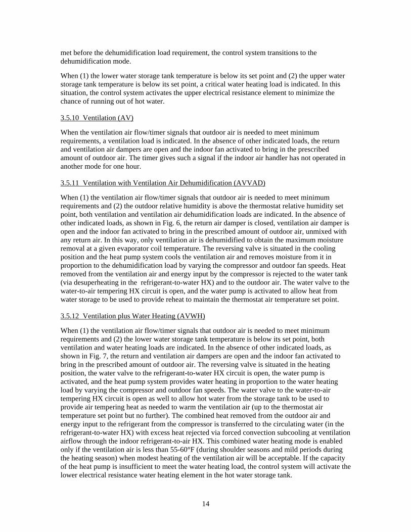
3.5.12 Ventilation plus Water Heating (AVWH)
When (1) the ventilation air flow/timer signals that outdoor air is needed to meet minimum requirements and (2) the lower water storage tank temperature is below its set point, both ventilation and water heating loads are indicated. In the absence of other indicated loads, as shown in Fig. 7, the return and ventilation air dampers are open and the indoor fan activated to bring in the prescribed amount of outdoor air. The reversing valve is situated in the heating position, the water valve to the refrigerant-to-water HX circuit is open, the water pump is activated, and the heat pump system provides water heating in proportion to the water heating load by varying the compressor and outdoor fan speeds. The water valve to the water-to-air tempering HX circuit is open as well to allow hot water from the storage tank to be used to provide air tempering heat as needed to warm the ventilation air (up to the thermostat air temperature set point but no further). The combined heat removed from the outdoor air and energy input to the refrigerant from the compressor is transferred to the circulating water (in the refrigerant-to-water HX) with excess heat rejected via forced convection subcooling at ventilation airflow through the indoor refrigerant-to-air HX. This combined water heating mode is enabled only if the ventilation air is less than 55-60°F (during shoulder seasons and mild periods during the heating season) when modest heating of the ventilation air will be acceptable. If the capacity of the heat pump is insufficient to meet the water heating load, the control system will activate the lower electrical resistance water heating element in the hot water storage tank.

15
When (1) the lower water storage tank temperature is below its set point and (2) the upper water storage tank temperature is below its set point, a critical water heating load is indicated. In this situation, the control system activates the upper electrical resistance element to minimize the chance of running out of hot water.
Fig. 6. Ventilation with ventilation air dehumidification (AVVAD).
3.5.13 Outdoor Coil Defrosting (OCD)
When (1) the outdoor air temperature is below a specified minimum (45°F, for example), and (2) a “defrost need” signal is received from a demand defrost sensor (e.g., difference between refrigerant exiting outdoor refrigerant-to-air HX and outdoor air temperature exceeds some defined limit) the need for a defrost cycle is indicated. In this case, the refrigerant reversing valve is situated in the cooling position, the return damper is open, and the ventilation air damper is closed, and the heat pump system operates the compressor and indoor fan to remove heat from the indoor air and move the combined heat and energy input by the compressor to the outdoor coil. With the outdoor fan off, the bulk of this energy is employed in melting the accumulated frost layer.
16
Fig. 7. Ventilation plus water heating (AVWH).
3.6 Speed Control Relationships and AS-IHP Performance for Selected Operating Modes
With a variable-speed heat pump, as the compressor speed varies to match the load, the indoor and outdoor airflows should be adjusted in somewhat similar measure to obtain highest efficiency (Miller 1988, Rice 1992). In addition, the refrigerant flow control should be adjusted with compressor speed to obtain optimal condenser exit subcooling, if possible, while the compressor inlet superheat is maintained at a value sufficient to maintain low superheat levels leaving the evaporator.1
As the compressor speed generally has a stronger effect on these optimums than the ambient, this variable was used as the independent control variable for the AS-IHP design. The ORNL Heat Pump Design Model (HPDM) was used with the breadboard IHP design and component
1Obtaining this optimal control over a range of ambients will generally require some adjustable level refrigerant charge storage means such as a suction line accumulator or other devices which can hold excess charge at some conditions and deliver needed charge back to the system at other conditions and operation modes.

17
performance specifications and data to determine an optimal set of control relationships for indoor blower and outdoor fan motor frequencies (directly proportional to speed) and condenser subcooling vs. compressor speed. This was done for a representative (target) set of cooling and heating ambients vs. compressor speed so that the effect of ambient conditions was also factored into the analysis.
3.6.1 Compressor Speed Ratio vs. Ambient in Cooling and Heating Modes
Figures 8 and 9 show the assumed target relationships between the compressor speed ratio and the ambient in cooling and heating modes, respectively, where ratios are shown for generality. (As all of the motors here are synchronous, the frequency ratios and the speed ratios are the same.) The design compressor frequency (at which the design cooling capacity is achieved) in our breadboard system is 79 Hz (speed or Hz ratio = 1.0). The desired speed range is wider in the heating mode than in the cooling mode to provide more heating capacity at ambients below about 32°F where typically the capacity of a single-speed compressor (at a speed ratio of 1) becomes insufficient to meet the heating load. Here we are proposing a maximum speed ratio of 1.5 or 50% overspeed to 118 Hz in this case. Rice (1988) has shown that compressors can be operated in constant power overspeed conditions in the heating mode since the torque requirements decrease along with the ambients. Because of this, the motor can be run at reduced volts/hertz ratios (fixed line voltage / increasing frequency) at these lower ambient heating conditions. This overspeed operation results in a significant increase in the rated HSPF per the DOE rating procedure. (Domanski 1988). The minimum assumed speed for our analysis was 28 Hz for both cooling and heating modes (0.35 speed ratio).
Target Compressor Speed Ratios vs Ambient-- Space Cooling Mode --
0.0
0.2
0.4
0.6
0.8
1.0
1.2
75 80 85 90 95 100 105
Ambient (F)
Com
pres
sor S
peed
Rat
io
Fig. 8. Target compressor speed ratios vs. ambient in the space cooling mode.

18
Target Compressor Hz Ratios vs Ambient-- Space Heating Mode --
0.0
0.2
0.4
0.6
0.8
1.0
1.2
1.4
1.6
20 25 30 35 40 45 50 55
Ambient (F)
Hz
Rat
io
Fig. 9. Target compressor speed ratios vs. ambient in the space heating mode.
3.6.2 Control Parameters vs. Compressor Speed Ratio in the Space Cooling and Heating Modes
The selected indoor blower and outdoor fan speed ratios and condenser subcooling control are shown in figures 10 and 11 as functions of the compressor speed ratios for cooling and heating mode, respectively. The nominal airflows are 500 cfm indoor and 1200 cfm outdoor. In the cooling mode, shown in Fig. 10, the airflow ratios drop off more slowly than the compressor speed, since the capacity and thus HX loading drops more gradually than compressor speed as well. (A one-to-one speed ratio relationship is shown by the dotted gray line.) This is because as the speed is lowered and the HX unloads, the evaporator pressure rises with increases in the refrigerant suction density entering the compressor. This slightly higher density tends to resist the capacity drop from the compressor speed reduction. In the heating mode, the airflows again drop off more slowly than the compressor speed for similar reasons. The maximum outdoor flow rate in the heating mode is reduced from the cooling mode by about 25% since the HX loading on the outdoor coil is reduced when the coil operates as an evaporator. At reduced compressor speeds in both modes, the optimal subcooling levels are lower as found by Miller (1988).

19
Airflow Ratios and Subcooling vs Compressor Speed Ratio
-- Space Cooling Mode --
0.0
0.2
0.4
0.6
0.8
1.0
1.2
0 0.2 0.4 0.6 0.8 1 1.2
Compressor Speed Ratio
AirF
low
Rat
io
2
4
6
8
10
12
14
Subc
oolin
g (F
)
Indoor Blow er
Outdoor Fan
CondenserSubcooling
Fig. 10. Control parameters versus compressor speed ratio in the space cooling mode.
Airflow Ratios and Subcooling vs Compressor Speed Ratio
-- Space Heating Mode --
0.0
0.2
0.4
0.6
0.8
1.0
1.2
0 0.2 0.4 0.6 0.8 1 1.2 1.4 1.6
Compressor Hz Ratio
Airf
low
Rat
io
0
5
10
15
20
25
30
Subc
oolin
g (F
)
Indoor Blow er
Outdoor Fan
CondenserSubcooling
Fig. 11. Control parameters versus compressor speed ratio in the space heating mode.
20
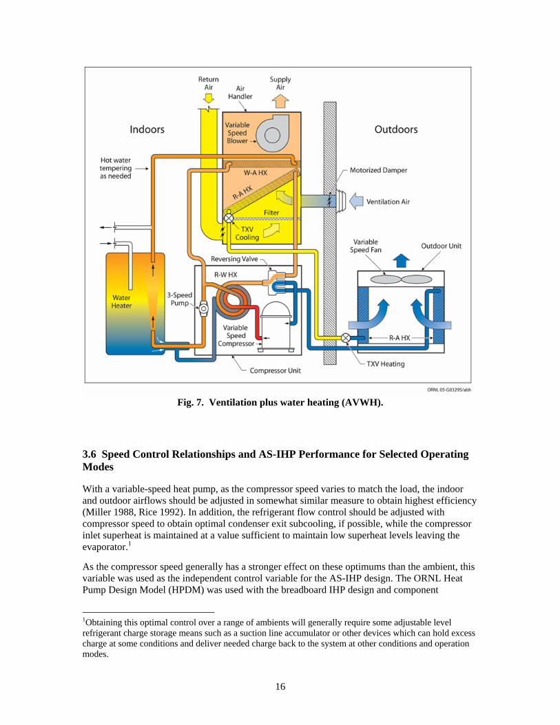
3.6.3 Target Speed Ratios and Refrigerant Flow Control vs. Ambient in Space Cooling and Heating Modes
In Fig. 12, the target speed ranges in cooling mode for all three modulating components are shown as a function of ambient along with the specified condenser subcooling and compressor inlet superheat levels. This plot shows the speed ranges for an expected average cooling load matching with ambient. As the cooling load varies from the expected load relationship, the compressor speed will adjust to match the load seen by the thermostat, and the airflows and subcooling levels would be adjusted based on the revised compressor speed. Fig. 13 shows a similar set of control values expected for an expected average heating load matching over the range of ambients. Again, depending on the actual heating load characteristics of a given building, the compressor speed would adjust to meet the actual load at a given ambient, and the other control parameters would be adjusted accordingly.
Target Speed Ratios and SC/SH vs Ambient-- Space Cooling Mode --
0.0
0.2
0.4
0.6
0.8
1.0
75 80 85 90 95 100 105
Ambient (F)
Spee
d R
atio
0
5
10
15
20
25
30
35
40
45
50
SH &
SC
(F)
Compressor
Indoor Blow er
Outdoor Fan
Subcooling
Superheat
Fig. 12. Target speed ratios and refrigerant flow control vs. ambient in the space cooling mode.

21
Target Speed Ratios and SC/SH vs Ambient-- Space Heating Mode --
0.0
0.2
0.4
0.6
0.8
1.0
1.2
1.4
1.6
20 25 30 35 40 45 50 55
Ambient (F)
Spee
d R
atio
0
5
10
15
20
25
30
35
40
45
50
SC &
SH
(F)
Compressor
Indoor Blow er
Outdoor Fan
Subcooling
Superheat
Fig. 13. Target speed ratios and refrigerant flow control vs. ambient in the space heating mode.
3.6.4 Target Compressor Speed Ratios For Space Heating, Space Cooling, Water Heating, and Ventilation Cooling Modes vs. Ambient
In Fig. 14, the target compressor operating speed ratios vs. ambient are summarized for space heating, space cooling, water heating, and ventilation cooling. Dedicated water heating is shown to operate at target maximum speed at 45°F and below, slowing to minimum speed at 65°F (from 45 to 90 Hz in this case). Expected operation range is from 40 to 80°F as beyond these ambients, space conditioning is expected to take priority with water heating provided by the other combination modes as described earlier, including desuperheating, heat recovery, and combined space and water heating. The compressor cannot be over sped in water heating mode as much as in space heating because the condensing saturation temperatures must reach 130°F or higher to heat the water to the 120°F set point. In this mode, the outdoor airflow rate relationship is the same as in space heating while the condenser subcooling is currently controlled as for space cooling.
Target speed ranges for ventilation cooling are also shown in Fig. 14. Two curves are shown for different humidity removal requirements, from 100% relative humidity outdoor air to space-neutral and from an average outdoor humidity ratio to space-neutral. In this mode, the airflow across the indoor coil is fixed at the ventilation flow rate (e.g., 144 cfm for the timed 20-min duration) and the compressor speed is increased to provide more dehumidification as needed based on the indoor humidity sensor (from 28 to 42 Hz for the average humidity case and 28 to 58 Hz for the high humidity case). The outdoor airflow and the condenser subcooling are controlled as in space cooling in the ventilation cooling mode.

22
Target Compressor Speed Ratio vs Ambient-- Different Operating Modes --
0.0
0.2
0.4
0.6
0.8
1.0
1.2
1.4
1.6
20 30 40 50 60 70 80 90 100 110
Ambient (F)
Spee
d R
atio
Space Heating
Water Heating
Space Cooling
Vent. DDH, 100% RH
Vent. DDH, Ave RH
Fig. 14. Target compressor speed ratios for various operating modes versus ambient.
(DDH = dedicated dehumidification; RH = relative humidity.)
These target speeds are to be used by the microprocessor as starting points for the various operating modes, to be adjusted by the thermostat controllers to meet the required indoor dry bulb temperature, humidity, or domestic hot water set points, with load following where possible for maximum efficiency. In the case of water heating, higher capacity output from the heat pump at the lower ambients is selected over higher coefficient of performance (COP) to avoid the need for resistance heat elements, which may be needed if the unit cannot keep up with hot water demand when space heating takes priority.
3.6.5 Target Air-Source IHP Space Heating and Cooling Performance vs. Ambient With Proposed Control Relationships for Load Tracking
In Fig. 15, the target performance of the AS-IHP is shown for space heating and cooling for the assumed load tracking behavior. This is where the compressor and indoor and outdoor fan speed ratios as well as the subcooling and superheat are assumed to follow the relationships given in figures 12 and 13 for space cooling and heating, respectively. The respective energy-efficiency ratios (EERs) are shown by the solid lines and the delivered capacities are given by the dotted lines. The points where the trend lines change slope are where the minimum and maximum compressor speeds are reached and the system reverts to ambient trends similar to a single-speed unit, but at minimum and maximum speeds. It can be seen from this plot that the design cooling capacity at 95°F is just over 15,000 Btu/h or 1.25 tons. Similarly at the maximum overspeed operation in heating mode, a heating capacity of nearly 13,000 Btu/h is reached at about 20°F ambient. Typically a single-speed heat pump has about the same heating capacity at 47°F as the

23
design cooling capacity and then drops with ambient to a much lower capacity at 20°F, having a similar capacity to the variable-speed system shown here only at the design speed of 79 Hz at 32°F ambient.
Target AS-IHP Space Heating and Cooling Mode Performance versus Ambient
4
6
8
10
12
14
16
18
20
22
10 20 30 40 50 60 70 80 90 100 110Ambient (F)
EER
(Btu
/W-h
)
0
2
4
6
8
10
12
14
16
18
Cap
acity
(MB
tuh)
Heating EERCooling EERHeating CapacityCooling Capacity
Fig. 15. Target air-source IHP space heating and cooling performance vs. ambient with
proposed control relationships for load tracking.
3.6.6 Target Air-Source IHP Water Heating Performance vs. Ambient With Proposed Control Relationships
The target water heating performance is shown in Fig. 16 over the expected ambient range for this mode of operation where hot water is produced with outside air as the source. The assumed inlet water temperature was 108°F, which is consistent with the rating point used in the Hydrotech2000 performance ratings. Here the water heating capacity ranges from about 14,000 Btu/h (equal to a 4.1-kW heating element) at 4°F ambient to just below 10,000 Btu/h at 65°F ambient. In the latter case, the lower heating output was selected to provide higher water heating COP, as there is no compelling need to heat the water faster at this ambient where there will be little if any call for coincident space cooling or heating. Accordingly, the delivered COPs for dedicated water heating range from about 2.8 at 45°F to 4.9 at 80°F, the highest ambient expected for outdoor source water heating. Note that in the cooling season, most water heating is expected to be done in heat recovery mode where both space cooling and hot water are delivered outputs and the net COP for water heating is thus much higher.

24
Target Performance vs Ambient-- Water Heating Mode --
0
1
2
3
4
5
6
35 40 45 50 55 60 65 70 75 80 85
Ambient (F)
CO
P
0
3
6
9
12
15
18
Cap
acity
(MB
tuh)
DHW COP
DHW Capacity
108F Inlet Water Temperature
Fig. 16. Target air-source IHP water heating performance vs. ambient with proposed control relationships.
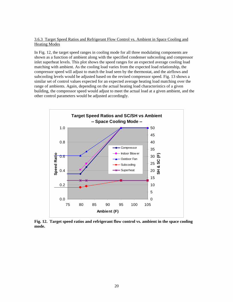
3.6.7 Target Air-Source IHP Ventilation Cooling Performance vs. Ambient With Proposed Control Relationships
Performance in the ventilation cooling mode from 70 to 80°F ambients is shown in Fig. 17, where an average outdoor humidity ratio of 0.0155 lbm water/lbm dry air is assumed with a constant ventilation flow rate of 144 cfm. The compressor speed was controlled in this case to provide a constant dehumidification rate and thereby supply air with space-neutral humidity with the outdoor coil airflow rate and subcooling adjusted according to compressor speed. In Fig. 18, the delivered sensible heat ratio is seen to range from 0.37 to 0.48 by directly working on the humidity ratio of the outdoor ventilation air without any dilution with indoor return air. This provides a high operating EER and even more importantly minimizes the tempering heat needed to offset the accompanying sensible cooling.
25
Fig. 17. Target air-source IHP ventilation cooling performance vs. ambient with proposed control relationships.
Sensible Heat Ratios for IHP Direct Ventilation Air Cooling(Fixed Average Humidity Ratio of Ventilation Air = 0.01555)
0.0
0.1
0.2
0.3
0.4
0.5
0.6
0.7
0.8
68 70 72 74 76 78 80 82Ambient Temperature (F)
Sens
ible
Hea
t Rat
io
Fixed Dehumidification Rate of 3.8 lbm/hr to Neutral Conditions
Fixed Ventilation Flow Rate and Moisture Load
Fig. 18. Target air-source IHP ventilation cooling sensible heat ratio (SHR)
vs. ambient with proposed control relationships.
Target EER Performance for IHP Ventilation Cooling(Fixed Average Humidity Ratio of Ventilation Air = 0.01555)
14
15
16
17
18
19
20
21
22
23
24
68 70 72 74 76 78 80 82Ambient Temperature (F)
EER
Fixed Dehumidification Rate of 3.8 lbm/hr to Neutral Conditions
Fixed Ventilation Flow Rate and Moisture Load
26
3.6.8 Target Air-Source IHP Ventilation Cooling Sensible Heat Ratio (SHR) vs. Ambient With Proposed Control Relationships
From the example results provided, it can be seen that the AS-IHP is capable of high performance over a range of operating modes. This performance is maximized by variable-speed compressors that can maintain high efficiency reasonably well over the range of speed ratios required for load matching. Comparison of predicted AS-IHP performance to that of the earlier Hydrotech2000 variable-speed system (Carrier 1989c) shows significant performance improvements with the higher efficiency rotary compressors presently available.
3.7 Other Possible Control Options or Approaches for Further Consideration
3.7.1 Option for Outside Air Economizer Mode
Within the current AS-IHP design, it is possible to include an outside air economizer mode. In this mode, the existing humidity sensor used to determine the need for ventilation cooling could be replaced with an enthalpy sensor to provide an indication of when outside air can be brought into the space for beneficial cooling. This mode could be initiated when there is a call for cooling while the outdoor air enthalpy is below that of the indoor air by a defined offset. In this mode, the return air damper could be opened to circulate an equal amount of return air along with at least three times the ASHRAE 62.2 continuous ventilation rate (e.g., 3 x 48 cfm = 144 cfm for an 1800-ft2 house) of outdoor air. This would be equivalent to the flow arrangement for the timed ventilation only mode with the difference being that in the economizer mode the airflow would be continuous until the cooling thermostat dry-bulb call was satisfied. To assist in effectively ventilating the house in this mode, the bathroom vent fans would be turned on as well (as is done in the Air-Cycler approach of Rudd, 1998). Limiting the outside air economizer flow to the same as for the ventilation only case would keep from having to increase the size of the ventilation air duct just for this mode of operation. If higher economizer airflow were needed for this function to be effective, the added cost of the larger duct and dampers and added control complexity would need to be weighed against the economizer cooling benefits.
3.7.2 Alternative Approach to Providing Dedicated Dehumidification Mode
An alternative to using heat-pump-provided hot water for air tempering in the dedicated dehumidification mode is the use of condenser subcooling and some partial condensing in an additional air-to-refrigerant subcooler coil located downstream of the indoor cooling coil. This approach can be used to recover waste heat directly for air tempering.
A drawback of this approach for use in an IHP is that a third HX coil would need to be employed as a condenser in series with the outdoor air-to-refrigerant condenser and the indoor refrigerant-to-water HX. This HX must be bypassed in some manner in the heating mode. Also, the charge management is expected to be more difficult with a third condenser on the high side of the refrigeration cycle, where most of the refrigerant charge is held.
A positive of this approach is that waste heat can be applied directly to the indoor air stream at a low sink temperature. If properly controlled, this can be a quite efficient method of providing air tempering and enhanced dehumidification. However, this heat input must be properly apportioned to prevent overheating of the indoor air as the subcooler coil will be quite effective in transferring heat because the air temperature entering the subcooler will typically be below 60°F. When water heating is also needed, the large temperature difference between the water inlet temperature and air inlet temperature to the subcooler would be expected to limit the amount of water heating that
27
was possible while also tempering the indoor air. In our current configuration air tempering and water heating can be done at the same time.
As one of our design goals was to keep the refrigeration system from becoming too complex, we decided to use the proposed design in lieu of three condensers in series. The current design also allows heat-pump-heated water made at moderate ambients to be used for ventilation air heating in the upper end of the heating season ambients, if desired. The drawback of using domestic hot water energy for tempering is that there is generally some energy penalty in providing this tempering heat relative to a subcooler system. The degree of this penalty depends on how much domestic hot water energy is provided by desuperheating and heat recovery during regular cooling operation as opposed to dedicated water heating with an outdoor air source and also on the average inlet water temperatures seen at the water-to-refrigerant HX.
A major U.S. HVAC manufacturer (Lennox 2006) recently released an add-on unit containing a subcooler coil and control module for the indoor air handler to enable enhanced dehumidification at SHR’s down to 0.3 or lower. To apply this approach to an IHP, the indoor subcooler HX would likely need to be resized to provide a dedicated dehumidification option, the control and performance of simultaneous water heating and air tempering would require further analysis, and the charge management issues of the various modes of multiple condenser operation would need to be addressed. Such an analysis would require that a capability to model systems with three condensers in series be developed and validated with lab tests.
4. AS-IHP SYSTEM SPECIFICATIONS
To accommodate operation in the enumerated modes, the system will be configured as a split-system air-source heat pump suggested to consist of three main sections: an indoor compressor section, an indoor air handler section, and an outdoor air handler section. (Note that the indoor air handler and compressor sections could be combined into one cabinet.)
Included in the indoor compressor section will be the refrigerant compressor, refrigerant accumulator, refrigerant reversing valve, water pump, refrigerant-to-water HX, and selected temperature sensors (with microprocessor as necessary).
Included in the indoor air handler section will be the indoor blower fan, refrigerant-to-air HX, refrigerant expansion device, water-to-air HX, and selected temperature sensors (with microprocessor as necessary) contained in an enclosure with return air and ventilation air dampers.
Included in the outdoor air handler section will be the fan, refrigerant-to-air HX, refrigerant expansion device, and selected temperature sensors (with microprocessor as necessary). Other operating modes such as an outside air economizer mode may be incorporated, if deemed cost effective in meeting performance goals.
The general performance goal of the system is to provide the energy services required by the 1800-ft2 NZEH specified for Atlanta (using the National Renewable Energy Laboratory’s Building Energy Optimization program) while using no more than 50% of the energy required by the baseline components (13.0 SEER, 7.7 HSPF, 0.90 EF) to provide the same services. The system will operate from 208/230V, single-phase, 60 Hz AC electrical service appropriate for residential service. The preferred system refrigerant is R-410A. The nominal system capacity as conceived is approximately 1.25 tons. Based on laboratory prototype preliminary tests, the system performance goals are 18 SEER and 11 HSPF at ARI standard rating conditions in Region IV

28
with the minimum design heating requirement. The target water heating net energy factor is 3 with tank losses included.
4.1 Refrigerant Compressor The concept requires a high-efficiency, hermetic, variable-speed motor/compressor. A suggested option is a rotary compressor with an electronically commutated, brushless, DC drive motor with a permanent magnet rotor. A minimum rated compressor-only EER of 11 at ARI 540 conditions (ARI 1999) is suggested with a recommended value of 11.5 at 58 Hz. Rated capacity at 58 Hz was 9500 Btu/hr to obtain the 1.25-ton design cooling capacity. The preferred variable speed ranges are at least 2.8 to 1 in space cooling, 2 to 1 in water heating and 3.6 to 1 in space heating. (A maximum speed range of 28 to 100 Hz, for example, was available in a laboratory prototype with applied speeds of 28 to 79 Hz space cooling, 45 to 90 Hz water heating, and 28 to 100 Hz space heating.) A higher maximum speed in heating mode up to 118 Hz is recommended to obtain better heating season performance, as shown in the earlier example.
4.2 Indoor Fan/Blower
The concept requires a high-efficiency, variable-speed motor/blower combination. A suggested option is a centrifugal fan driven directly by an integral electronically commutated motor with pulse-width-modulation speed control. The suggested variable speed range is at least 3.5 to 1 with constant airflow control capability.
4.3 Outdoor Fan
The concept requires a high-efficiency, variable-speed motor/fan combination. A suggested option is a multi-bladed propeller fan driven directly by an integral electronically commutated motor with pulse-width-modulation speed control. The suggested variable speed range is at least 2 to 1.
4.4 Refrigerant-to-Water HX
The suggested arrangement is counterflow, helical, tube-in-tube with a single refrigerant circuit in the annulus and a single water circuit in a central convoluted water tube. Water-side pressure drop should be no more than 3 psi at 3 gpm water flow. The minimum UA heat transfer rating at maximum water heating speed and 1.8 gpm water flow should be no less than 1075 Btu/hr-F to give 1.25 tons of water heating at 47°F outdoor ambient temperature. The construction must be double-walled, vented, and approved for potable water use. Suitable provision must be made for either prevention of water-side fouling or access to surfaces subject to such fouling for periodic maintenance cleaning.
4.5 Water-to-Air HX
The suggested arrangement is a perpendicular coil using copper tubing with aluminum fins. The minimum recommended UA heat transfer rating for this coil is 82 Btu/hr-F. Suitable provision must be made for either prevention of water-side fouling or access to surfaces subject to such fouling for periodic maintenance cleaning.

29
4.6 Indoor Refrigerant-to-Air HX
The suggested arrangement is a sloped coil using grooved copper tubing with enhanced aluminum fins. The minimum recommended UA heat transfer rating for this coil is 725 Btu/hr-F at design cooling conditions.
4.7 Outdoor Refrigerant-to-Air HX
The suggested arrangement is a wrap-around coil using copper tubing with enhanced aluminum fins. The minimum recommended UA heat transfer rating for this coil is 1425 Btu/hr-F at design cooling conditions.
4.8 Electrical Resistance Water Heating Elements
Both lower and upper electrical resistance water heating elements are recommended to have 4.5 kW heating capacity at 230 V.
4.9 Water Pump
A three-speed potable water pump rated for 15 feet of head at 3 gpm for duties up to 200°F, 150 psig working pressure is suggested.
4.10 Hot Water Storage Tank
An insulated potable hot water storage tank with a minimum capacity of 50 gallons is recommended.
5. CONCEPTUAL DESIGN FOR GROUND-SOURCE IHP
This concept is similar to the AS-IHP described earlier but with the outdoor air coil replaced with a refrigerant-to-water HX and with secondary fluid pumped to a ground-source HX, making a ground-coupled version of the IHP. As with other ground-source heat pumps, the GS-IHP does not require a defrost cycle, and with a properly sized ground HX operates with heat source and sink temperatures that are less extreme than outdoor air all year long. Fig. 19 shows the annual variation in earth temperatures at the surface (essentially equal to air temperature variation) and at various depths for a central U.S. location (Stillwater, OK). These illustrate possible source temperatures for a horizontal-loop, ground-source HX. Temperature extremes are about 10°F lower in summer and higher in winter at a 5-ft depth than those for the air in this location. Fig. 20 shows average well water temperatures (measured at depths ranging from 50 ft to 150 ft) around the continental United States. They range from about 45 to 75°F north to south (approximately equal to average annual air temperatures) and are indicative of possible source temperatures for a vertical-loop ground-source HX. In either case they constitute a more favorable heat source and sink than the outdoor air for a heat pump system.

30
Fig. 19. Annual ground temperature at several depths.
As a consequence of this source–sink temperature advantage, the GS-IHP can enjoy a performance advantage over its AS-IHP counterpart. In the FY05 HVAC options scoping assessment, hourly analyses of a geothermal heat pump with desuperheater and an air-source heat pump with desuperheater showed that the former consumed from 3% to more than 13% less energy than the latter (Baxter 2005). The greatest reduction occurred in the coldest climate location considered in that study (Chicago). It is expected that the GS-IHP would achieve a similar range of annual energy use reductions over the AS-IHP.

31
Fig. 20. Ground water temperatures in wells ranging from 50 ft to 150 ft in depth (National Water Well Institute).

32
5.1 GS-IHP Equipment Concept
The GS-IHP concept, shown schematically in Fig. 21, uses one variable-speed modulating compressor, a variable-speed fan, two multiple-speed pumps, and a total of four heat exchangers: one air-to-refrigerant, two water-to-refrigerant, and one air-to-water) to meet all the HVAC and water heating (WH) loads.
Fig. 21. Conceptual diagram of a central forced-air electric air-source integrated heat
pump, showing operation in space-cooling mode.
One unique aspect is that the ventilation air is conditioned by the heat pump in both space cooling and space heating modes, and on demand if neither heating nor cooling is required. The unit also cycles on demand to dehumidify the space whether or not heating or cooling is required. The air-to-water HX (water coil in Fig. 21) uses heat recovery hot water generated in the space cooling and dehumidification modes to temper the ventilation air, as needed, for space-neutral conditions. Compressor, indoor fan, and water pump speed modulation is used to control indoor humidity and temperature, when needed. (Note that both water heating and indoor air tempering can be done at the same time.)
A schematic of the GS-IHP concept is shown in Fig. 22. The basic heat pump system is similar to a conventional water-source heat pump [compressor, air coil (refrigerant-to-air HX), ref/water coil (refrigerant-to-water HX 1), indoor blower, ground loop pump, refrigerant piping, flow controls, etc.]. To complete the GS-IHP system the following are added to the basic heat pump: water heater (with backup electric elements and controls), an additional refrigerant-to-water HX (2) and multi-speed pump (for water heating), connecting piping between the water heater and heat pump, a water-to-air HX coil (for tempering heating during dehumidification operation), and a short duct with motorized damper for ventilation air.

33
Fig. 22. Concept drawing of GS-IHP system, dedicated dehumidification mode shown.
A single-package concept for the equipment is proposed with both refrigerant-to-water HX’s and pumps located in the lower compressor section, and ventilation air inlet, return air duct, and supply air duct connected to the upper air handler section. This differs significantly from the packaging concept envisioned for the AS-IHP (at least two separate units, one indoor and one outdoor). Given that the source temperatures for the GS-IHP will be less extreme than for the AS-IHP case, compressor cooling needs should be less as well, enabling use of the single-package concept.
5.2 Ground-Source HX Options
The first option is to circulate a secondary fluid from refrigerant-to-water HX 1 to a high-density polyethylene (HDPE) pipe loop in a vertical bore configuration (vertical U-tube HX). This is similar to the ground HX type used most often in conventional ground-coupled (or geothermal) heat pumps.
The second option is to use a horizontal HDPE pipe loop with a solid water sorbent (SWS) material to enhance performance (Baxter 2007). The SWS-enhanced environmental coupling concept (Ally 2006a) is being investigated for its potential to reduce the size (and cost) of the ground HX required for the GS-IHP. Results of field experiments conducted at a research house

34
at a Habitat for Humanity site in Lenoir City, TN, indicate that a horizontal ground HX of about 700 ft of ¾-inch HDPE pipe surrounded by 80 lb of SWS material and 3200 lb of water enclosed in a vapor barrier surrounding the pipe would be sufficient to handle the peak heat rejection load from a 1-ton heat pump system. The results further indicate that the performance of the SWS-enhanced HX in the experiment is achieving heat transfer efficiency equivalent to that of soil with a thermal conductivity seven times greater than the native soil at the site (Ally 2006b). Parametric analyses conducted as part of the FY05 scoping study (Baxter 2005) indicated that SWS enhancement equivalent to a thermal conductivity increase of 10 – 15 times greater than native soil would be needed to achieve energy efficiency equal to that of a vertical loop ground HX. This would require doubling the amounts of SWS material and water to 160 lb and 6400 lb, respectively, for a 1-ton system. It is further assumed for purposes of this study that the ground HX peak heat rejection capacity could be doubled again by doubling the SWS and water (to 320 lb SWS and 12,800 lb water) enabling the HX length to be cut in half — to 350 ft of HDPE pipe for a 1-ton system. This pipe length would fit comfortably within the existing foundation and utility trenches needed for an 1800-ft2 two-story ZEH with a 30 x 30 ft perimeter like the one used for the initial IHP business case assessment (Baxter 2007). If this SWS enhancement approach is successful, cost for a GS-IHP can be reduced significantly, to approximately the same as that of an AS-IHP (Baxter 2007).
5.3 Operational Control Concept
In general, the control approach for the GS-IHP will be very similar to that being proposed for the AS-IHP system, but with two significant differences. First, given that there is no outdoor air coil there will be no need to have a defrost cycle with its attendant control scheme and no need for defrost tempering heat. Second, since the GS-IHP will have the advantage of more moderate heat source–sink temperatures than the AS-IHP, the compressor speed range need not be as wide. This advantage is greatest during extreme weather, which further mitigates the need to have high compressor speeds to deliver extra heating or cooling capacity to meet extreme house loads.
Compressor speed ranges being proposed for the AS-IHP and GS-IHP are shown below.
Table 6. Proposed compressor speed ranges for air-source and ground-source IHPs (assuming use of the same nominal compressor size as for the AS-IHP lab prototype)
Air Source IHP Ground Source IHP
Heating 4.2-1 (28 Hz to 118 Hz driving frequency) to maximize heating capacity during maximum heating load (low ambient temperature) periods
3-1 (30 Hz to 90 Hz)
Cooling 2.8-1 (28 Hz to 79 Hz) less than for heating in order to avoid overloading the compressor at high ambient conditions;
2.5 to 1 (30 to 75Hz)
Dedicated water heating
2-1 (45 Hz to 90 Hz) 2-1 (40 Hz to 80 Hz)
Alternatively, it may be possible to reduce the size of the compressor and use similar speed ranges as proposed for the AS-IHP. Both approaches will be investigated analytically.

35
In addition, a multiple-speed pump (2 or 3 speeds) is proposed initially for the ground loop fluid circulator rather than an inverter-driven variable-speed pump. This will reduce the number of inverter drives from three (for the AS-IHP) to two.
5.4 Plan for Further Development of GS-IHP Concept
Assuming a positive decision from DOE–BT on continued development, we propose to assemble a manually operated breadboard prototype of the conceptual GS-IHP and test over an expected range of operating conditions in the same modes as tested for the AS-IHP previously. We will start with the AS-IHP laboratory prototype experience, employing appropriate refrigerant, component, and instrumentation options.
Initially, the proposed compressor speed ranges above will be used along with the indoor blower speed range used for the AS-IHP and the proposed multiple-speed loop pump. We will verify water-to-refrigerant HX performance over the flow ranges experienced on both sides across the various modes. Next we will determine steady-state system performance in all operating modes using an auxiliary source–sink load system to simulate the expected range of entering ground HX fluid temperature conditions to the water-to-refrigerant HX. Acquired data will be compared with predictions of the calibrated ORNL heat pump design model (HPDM), with special attention to the adequacy of simulations of the operation of the water-to-refrigerant HX interface between the heat pump and the ground loop (refrigerant evaporation). The operational control and charge management approaches developed for the AS-IHP would also be evaluated to determine their adequacy for the ground-source design and modified if necessary. HPDM will be used to determine optimal control algorithms for indoor blower and pump speeds vs. the compressor size and speed range options listed above.
6. REFERENCES
ARI (1999). ARI Standard 540-1999: Positive Displacement Refrigerant Compressors and Compressor Units. Air-Conditioning and Refrigeration Institute.
Ally, M. R. (2006a). Data and Analyses of SWS performance in Field Experiments for Interim DOE Go/No-Go Decision: Oak Ridge National Laboratory, June 30 DRAFT.
Ally, M. R. (2006b). Personal communication to Van Baxter, July 6.
ASHRAE (2004). ANSI/ASHRAE Standard 62.2-2004: Ventilation and Acceptable Indoor Air Quality in Low-Rise Residential Buildings.
Baxter, V. (2005). HVAC Equipment Design Options for Near-Zero-Energy Homes – A Stage 2 Scoping Assessment. ORNL/TM-2005/194. November.
Baxter, V. (2007). Integrated Heat Pump HVAC Systems for Near Zero Energy Homes (NZEH) – Business Case Assessment. ORNL/TM-2007/064. May.
Carrier Corporation (1989a). Carrier Heating and Cooling Residential Heat Pump System Start-up and Service Manual (HydroTech 2000 Models), July.
Carrier Corporation (1989b). Carrier Start-up and Troubleshooting Service Manual (HYDROTECH 2000 Residential Heat Pump).
36
Carrier Corporation (1989c). Carrier Heating and Cooling 38QE/40QE Advanced Technology Heat Pump System, September.
Domanski, P. A., 1988. Recommended Procedure for Rating and Testing Variable Speed Air Source Unitary Air Conditioners and Heat Pumps, NBSIR 88-3781, May.
Fanney, A. H. (1993). Field Monitoring of a Variable-Speed Integrated/Water-Heating Appliance, NIST Building Science Series 171, June.
International Institute of Refrigeration, 2005. Technology: Briefs: VRF (Variable Refrigerant Flow), IIR Newsletter, No. 23, p. 5, July.
Lennox, Engineering Data, Model EDA, Humiditrol Whole-Home Dehumidification System, Bulletin No. 210430, March 2006.
Miller, W. A. 1988. “Laboratory Capacity Modulation Experiments, Analyses, And Validation,” Proceedings of the 2nd DOE/ORNL Heat Pump Conference: Research and Development on Heat Pumps for Space Conditioning Applications, CONF-8804100, April 17-20, 1988, Washington, D.C., April, pp. 7-21.
Nordyne Corporation. Nordyne Powermiser Installation and Certification—Alabama Power Company Heat Pump Training Center.
Rice, C.K. 1992. "Benchmark Performance Analysis of an ECM-Modulated Air-to-Air Heat Pump with a Reciprocating Compressor," ASHRAE Transactions, Vol. 98, Part1, 1992 pp.430-50
Rice, C.K. 1988. "Efficiency Characteristics of Speed Modulated Drives at Predicted Torque Conditions for Air-to-Air Heat Pumps," ASHRAE Transactions, Vol. 94, Part 1, pp.892-921.
Rudd, A.F. 1998. “Design/Sizing Methodology and Economic Evaluation of Central-Fan-Integrated Supply Ventilation Systems.” Proceedings of the 1998 ACEEE Summer Study on Energy Efficiency in Buildings, 23-28 August, Pacific Grove, California. American Council for an Energy Efficient Economy, Washington, DC.
Tomlinson, J. J., C. K. Rice, R.W. Murphy, Z. Gao. (2005), Assessment and Initial Development of a Small, High-Efficiency Heat Pump System for NZEH, September.
U. S. Patent 1991a. No. 5,050,394, “Controllable Variable Speed Heat Pump for Combined Water Heating and Space Cooling,” September 24.
U. S. Patent 19941b. No. 5,052,186, “Control of Outdoor Air Source Water Heating Using Variable-Speed Heat Pump,” October 1.
U. S. Patent 1991c. No. 5,062,276, “Humidity Control for Variable Speed Air Conditioner,” November 5.
U. S. Patent 1992. No. 5,081,846, “Control of Space Heating and Water Heating Using Variable Speed Heat Pump,” January 21.
U. S. Patent 1993. No. 5,269,153, “Apparatus for Controlling Space Heating and/or Space Cooling and Water Heating,” December 14.
U. S. Patent 1997. No. 5,628,201, “Heating and Cooling System with Variable Capacity Compressor,” May 13.