integrated assessment of detailed kiln behaviour - report - industry example rotary kiln -...
TRANSCRIPT

Dubravka Mijuca Consulting
DOCUMENT NO: DMC807-TM-04
REPORT ON
INTEGRATED ASSESSMENT OF DETAILED KILN BEHAVIOUR
CLIENT: ONESTEEL WHYALLA
PROJECT TITLE: KILN AND GIRTH GEAR FLANGE BOLTS ASSESSMENTS
Copyright Notice: Dubravka Mijuca Consulting and IT1 Pty Ltd 2007 The copyright in this work is vested in Dubravka Mijuca Consulting and IT1 Pty Ltd and the document is issued in confidence for the purpose only for which it is supplied. It must not be reproduced in whole or in part except under an agreement with, or with the consent in writing of, Dubravka Mijuca and IT1 Pty Ltd and then only on the condition that this notice appears in any such reproduction. No information as to the contents or subject matter of this document or any part thereof may be given orally or in writing or communicated in any manner whatsoever to any third party without prior consent in writing of Dubravka Mijuca Consulting and IT1 Pty Ltd
0 24//4/07 Issued for use
Rev Date Description By Appd Appd

Dubravka Mijuca Consulting
Pellet Kiln Investigation — page 2
IT – 1 Consulting and R&D Engineers Commercial In-Confidence
TABLE OF CONTEST
1. SCOPE OF THE WORK........................................................................................ 5 2. EXECUTIVE SUMMARY....................................................................................... 6
2.1 COLD KILN ....................................................................................................................................... 7 2.1.1. SHELL ...................................................................................................................................................... 7 2.1.2. GIRTH GEAR.............................................................................................................................................. 7
2.2 TANGENT PLATES................................................................................................................................ 7 2.2.1. REACTIONS AT THE SUPPORTS ....................................................................................................................... 7 2.2.2. CLAMP FORCE ON THE JOINT OF TWO HALVES OF GIRTH GEAR ................................................................................ 7
2.3 NORMAL OPERATION............................................................................................................................ 8 2.3.1. TEMPERATURES IN THE KILN .......................................................................................................................... 8 2.3.2. KILN ........................................................................................................................................................ 9 2.3.3. SHELL ...................................................................................................................................................... 9 2.3.4. GIRTH GEAR............................................................................................................................................ 10 2.3.5. TANGENT PLATES...................................................................................................................................... 10 2.3.6. TYRES.................................................................................................................................................... 10 2.3.7. FEED END AND DISCHARGE END .................................................................................................................... 10 2.3.8. REACTIONS AT THE SUPPORTS ..................................................................................................................... 11 2.3.9. CLAMP FORCE ON THE JOINT OF TWO HALVES OF GIRTH GEAR .............................................................................. 11
2.4 KILN WITH HOT SPOTS ........................................................................................................................12 2.4.1. HOT SPOT AT 0 O’CLOCK ............................................................................................................................ 12 2.4.2. HOT SPOT AT 9 0’CLOCK............................................................................................................................. 13
2.5 KILN WHICH STOPS ITS ROTATION BY PINION DRIVE AT 7 0’CLOCK BRAKES .........................................................14 2.5.1. CLAMP FORCE ON THE JOINT OF TWO HALVES OF GIRTH GEAR .............................................................................. 14
2.6 CLAMP FORCE ANALYSIS FOR THE COLD, NORMAL OPERATING, BRAKING AND KILN WITH HOT SPOTS ........................15 2.7 ORIGINAL AND PROPOSED FLANGE BOLTS STRESS ANALYSIS FOR THE COLD, NORMAL OPERATING, BRAKING AND KILN WITH HOT SPOTS ...............................................................................................................................................16
3. MATERIAL PROPERTIES....................................................................................17 3.1 MATERIAL TEMPERATURE DEPENDENCES TABLES ........................................................................................18
4. MASS BILLS .......................................................................................................20 5. EXTERNAL LOADS............................................................................................21
5.1 MECHANICAL LOADS...........................................................................................................................21 5.2 THERMAL LOADS ...............................................................................................................................22
6. BOUNDARY CONDITIONS .......................................................................................24 6.1 THERMAL BOUNDARY CONDITIONS ..........................................................................................................24 6.2 MECHANICAL BOUNDARY CONDITIONS .....................................................................................................25
7. FLANGE BOLTS ...................................................................................................27 8. STEADY STATE HEAT TRANSFER FE ANALYSIS ...................................................28
8.1 REFRACTORY....................................................................................................................................29 8.2 PELLET ...........................................................................................................................................30 8.3 SHELL ............................................................................................................................................31 8.4 GIRTH GEAR AND TANGENT PLATES ........................................................................................................34 8.5 TABLES AND DIAGRAMS.......................................................................................................................38
9. ELASTOSTATICS RESULTS OF THE KILN IN NORMAL OPERATION ........................40 9.1 DISPLACEMENTS................................................................................................................................40
9.1.1. ELONGATION ........................................................................................................................................... 40

Dubravka Mijuca Consulting
Pellet Kiln Investigation — page 3
IT – 1 Consulting and R&D Engineers Commercial In-Confidence
9.1.2. DEFLECTION OF THE SHELL ......................................................................................................................... 41 9.1.3. RADIAL AND TANGENTIAL DISPLACEMENT OF THE KILN ...................................................................................... 41 9.1.4. RADIAL DISPLACEMENT OF THE SHELL............................................................................................................ 43 9.1.5. TANGENTIAL DISPLACEMENT OF THE SHELL ..................................................................................................... 44 9.1.6. RADIAL DISPLACEMENT OF THE SHELL CENTRE SECTIONS..................................................................................... 45 9.1.7. RADIAL DISPLACEMENT OF THE FEED END AND THE DISCHARGE END ..................................................................... 46 9.1.8. EXAGGERATED DISPLACEMENTS OF THE SHELL, TANGENT PLATES, GIRTH GEAR AND TYRES ....................................... 48 9.1.9. RADIAL AND TANGENTIAL DISPLACEMENT OF THE GIRTH GEAR............................................................................. 49 9.1.10. RADIAL AND TANGENTIAL DISPLACEMENTS OF THE TANGENT PLATS ...................................................................... 50 9.1.11. RADIAL AND TANGENTIAL DISPLACEMENT OF THE TYRE...................................................................................... 51 9.1.12. RADIAL DISPLACEMENT OF THE SHELL BELLOW TYRE .......................................................................................... 52 9.1.13. RELATIVE DISPLACEMENT BETWEEN SHELL AND UPHILL TYRE............................................................................... 53 9.1.14. RELATIVE DISPLACEMENT BETWEEN SHELL AND GIRTH GEAR ............................................................................... 55
9.2 STRESSES........................................................................................................................................57 9.2.1. VON MISES STRESS OF THE SHELL ................................................................................................................ 57 9.2.2. RADIAL STRESS OF THE SHELL ..................................................................................................................... 58 9.2.3. TANGENTIAL STRESS OF THE SHELL............................................................................................................... 59 9.2.4. LONGITUDINAL BENDING STRESS.................................................................................................................. 64 9.2.5. GIRTH GEAR STRESSES .............................................................................................................................. 65 9.2.6. TANGENT PLATES STRESSES ........................................................................................................................ 67
9.3 REACTIONS AT THE SUPPORTS...............................................................................................................70 9.4 TABLES AND DIAGRAMS .......................................................................................................................72 9.5 STRESS CALCULATION OF FLANGE BOLTS...................................................................................................76
9.5.1. CALCULATION PROCEDURE .......................................................................................................................... 77 9.5.2. MATERIAL ............................................................................................................................................... 77 9.5.3. BOLT DESIGNS ......................................................................................................................................... 77 9.5.4. PRELOADED BOLTS UNDER STATIC LOADING.................................................................................................... 77 9.5.5. EXTERNAL LOADING................................................................................................................................... 78 9.5.6. TEMPERATURE OF THE BOLT ........................................................................................................................ 78 9.5.7. POSITIONS OF GIRTH GEAR EXAMINED........................................................................................................... 78 9.5.8. THEORY OF THE PRELOADED BOLTED JOINTS.................................................................................................... 80 9.5.9. BOLT DESIGN M48X3, L=455 MM, 50 MM, ROLLED THREAD OUT ....................................................................... 81 9.5.10. BOLT DESIGN M48X3, L=505 MM, D=44 CONT........................................................................................... 84 9.5.11. STRESSES AT CENTRE OF THE FLANGE BOLTS................................................................................................... 86
9.6 FORCES IN FLANGE BOLTS....................................................................................................................87 9.7 STRESSES AT THE CONTACT SURFACES OF GIRTH GEAR – ORIGINAL FLANGE BOLTS DESIGN ...................................88
10. HOT SPOT OPERATING CONDITION..........................................................................90 10.1 HOTSPOT ON 0 DEG.......................................................................................................................92
10.1.1. TEMPERATURES ........................................................................................................................................ 92 10.1.2. DISPLACEMENTS FOR KILN WITH HOT SPOT AT 0 DEGREES (12 O’CLOCK) ............................................................... 94 10.1.3. STRESS FOR KILN WITH HOT SPOT AT 0 DEGREES............................................................................................. 96 10.1.4. REACTIONS AT THE SUPPORTS FOR THE SHELL WITH HOT SPOT AT 12 O’CLOCK ........................................................ 99
10.2 HOTSPOT ON 90 DEG (9 O’CLOCK)...................................................................................................100 10.2.1. TEMPERATURES FOR THE KILN WITH HOT SPOT AT 90 DEGREES..........................................................................100 10.2.2. DISPLACEMENTS FOR THE KILN WITH HOT SPOT AT 90 DEGREES.........................................................................101 10.2.3. STRESSES FOR THE KILN WITH HOT SPOT AT 90 DEGREES .................................................................................102 10.2.4. REACTIONS AT THE SUPPORTS FOR SHEL WITH HOT SPOT AT 9 O’CLOCK ................................................................104
Dubravka Mijuca Consulting
Pellet Kiln Investigation — page 4
IT – 1 Consulting and R&D Engineers Commercial In-Confidence
10.3 TABLES AND DIAGRAMS ................................................................................................................105 10.4 STRESS CALCULATION OF FLANGE BOLTS UNDER HOTSPOTS .............................................................107 10.5 STRESSES AT CENTRES OF THE FLANGE BOLTS .................................................................................108 10.6 STRESSES AT THE CONTACT SURFACES OF GIRTH GEAR – HOTSPOT AT 0 DEGREES – ORIGINAL FLANGE BOLTS.....110 10.7 STRESSES AT THE CONTACT SURFACES OF GIRTH GEAR – HOTSPOT AT 0 DEGREES – PROPOSED FLANGE BOLTS....111
11. BRAKING OF THE ROTATION OF THE KILN IN NORMAL OPERATION...................112 11.1 REACTION FORCES ......................................................................................................................112 11.2 STRESSES AT THE CONTACT SURFACES OF GIRTH GEAR – BRAKING KILN – ORIGINAL BOLTS ..........................114 11.3 STRESSES OF THE FLANGE BOLTS.....................................................................................................115
12. ELASTOSTATICS ANALYSIS OF THE COLD KILN ................................................116 12.1 DISPLACEMENTS .........................................................................................................................116
12.1.1. ELONGATION ..........................................................................................................................................116 12.1.2. RADIAL DISPLACEMENTS............................................................................................................................116 12.1.3. EXAGGERATED DISPLACEMENTS OF THE SHELL SECTION 4..................................................................................118 12.1.4. EXAGGERATED DISPLACEMENTS OF THE SHELL, TANGENT PLATES AND TYRES .........................................................119
12.2 STRESS ....................................................................................................................................120 12.2.1. RADIAL STRESS OF THE SHELL ....................................................................................................................120 12.2.2. TANGENTIAL STRESS ................................................................................................................................121
12.3 STRESSES AT THE CONTACT SURFACES OF GIRTH GEAR – COLD KILN – ORIGINAL BOLTS ..............................124 12.4 STRESSES AT THE CENTRE OF THE FLANGE BOLTS.................................................................................125 12.5 REACTIONS ATE THE SUPPORT OF THE COLD KILN..................................................................................126
13. CONTACT ANALYIS.............................................................................................127 14. REMARK..........................................................................................................128 15. REFERENCES .................................................................................................128

Dubravka Mijuca Consulting
Pellet Kiln Investigation — page 5
IT – 1 Consulting and R&D Engineers Commercial In-Confidence
1. SCOPE OF THE WORK
This report is the outcome of a research consultancy undertaken by the Professor Dubravka Mijuca in 2007 for It-1. The overall aim of the work was to provide insight in detailed pellet kiln behavior under normal operating condition. To address these questions a series of materially nonlinear contact finite element analyses have been under taken using fully 3D finite element analyses per geometry and physical lows, understanding that both material and deformation have nonlinear behaviour. Presently, Normal Operating Condition understands that no any of the structural parts of the kiln have compromised its structural integrity, while Hot Spots Condition understands that refractory has lost its integrity in some region of the kiln.
Rotary kilns are used to heat solids to the point where a required chemical reaction(s) takes place. The rotary kiln is basically a rotating inclined cylinder. Solids retention time in the kiln is an important design factor and is set by proper selection of the diameter, length, speed, slope and internals design. There are two basic types of rotary kilns; direct fired and indirect fired.
The present pellet kiln shell is a cylinder about six meters in diameter and 36.1188 meters long. Its purpose is to roast iron ores. The mass of the kiln is 883743.62 kg, of which 180330 kg is the mass of the pellet material. The longitudinal axis of the cylinder is angled slightly downwards at the discharge end of the cylinder by 2.39 degrees. Iron ore pellets are introduced at the feeder end and, as the cylinder revolves, the pellets roll around inside the kiln and are heated to more than 1200°C. When the pellets reach the discharge end of the kiln they roll out into a chute. The kiln is completely lined with refractory bricks, which are butted up against a steel hoop, that is, bricking ring. The last 1200mm of the kiln at the discharge end is known as the discharge lip. The discharge lip consists of refractory material about 200mm thick, which is rammed against the walls of the kiln, and is anchored by steel anchors welded to the shell of the kiln. When the refractory material is heated it becomes rock hard and insulates the steel shell of the kiln from the intense heat inside.
The mechanical boundary conditions are applied at the Tyres on contact between Tyre and support rollers, and on the contact between axial thrust roller and uphill tyre. Further, boundary conditions per steady state heat problem are the radiative and convective heat transfer inside the kiln and convection on the outside surfaces of kiln.
The aim of this work, in relation to the bolts, was to find the stress range in the bolts during a single rotation of the kiln, in order to identify the source of the failure of the Flange Bolts on Girth Gear. The new bolt configuration with the longer bolts and the spacers is investigated also. If the new design results in a lower stress range, then it is an improvement.
This study has investigated the structural adequacy of the kiln shell for its normal and abnormal operating conditions, also. The investigation has included the Strength of the shell under normal conditions.
The results are obtained by the multiscale Finite Element thermo-mechanical nonlinear contact analysis. The maximal axial dimension of the kiln is 36118.8mm, while minimal axial dimension of the finite elements use is 0.1mm, which give us ratio of 4E5, which classify this analysis as multiscale. The materially nonlinear contact finite element analysis has included:
• Displacements, Stresses and Reactions in the cold kiln • Temperature, Displacements, Stresses and Reactions in the kiln in normal operation • Temperature, Displacements, Stresses and Reactions in the kiln with hot spots • Displacements, Stresses and Reactions in the kiln which brakes • Clamp force analysis for the Cold, Normal Operating, Braking and Kiln with Hot Spots • Original and Proposed Flange Bolts Stress analysis for the Cold, Normal Operating, Braking
and Kiln with Hot Spots

Dubravka Mijuca Consulting
Pellet Kiln Investigation — page 6
IT – 1 Consulting and R&D Engineers Commercial In-Confidence
2. EXECUTIVE SUMMARY
The kiln in 5 operational conditions are presently examined
1) cold kiln
2) normal operation
3) shell with hot spot at 12 o’clock
4) shell with hot spot at 9 o’clock
5) when pinion at 7 o’clock brakes
/The position are given as the kiln discharge is seen as the clock face, and observer is looking at it from outside of the kiln./
The differences in reaction forces at the support for these 5 cases are given in the next table:
Table Reactions at the supports
Kiln uphill left tyre
uphill right tyre
downhill left tyre
downhill right tyre
Intensity of summation vector
Cold 2037056 2618348 2482083 2704425 9841912
Normal Operation 2037506 2618348 2482083 2704425 9842362
Hot Spot 12 o’clock 2035927 2617219 2481862 2704203 9839211
Hot Spot 9 o’clock 2035982 2617273 2481882 2704224 9839361
Pinion at 7 o’clock brakes
1938041 2397180 2444210 2619829 9399260

Dubravka Mijuca Consulting
Pellet Kiln Investigation — page 7
IT – 1 Consulting and R&D Engineers Commercial In-Confidence
2.1 COLD KILN
Kiln does not extend its length in cold state.
Minimal and maximal radial displacements of the kiln are from -6.2 to 4.5 mm respectively.
Table Min/Max and averaged values of displacements and stresses of the cold kiln Min/Max and Averaged Values
Elongation [mm]
Radial displacement [mm]
Tangential displacement [mm]
Von Mises Stress [MPa]
Tangential Stresses
Overall 0 [-6.2 to 4.51] [-25.6, 21.3] Shell [-6.2 and 4.51]
Girth Gear 8.29 8.29 MPa Tangent Plates
[-32.1. 35.2] 1.6
2.1.1. SHELL
Minimal and maximal radial displacements of the shell in cold kiln are -6.2 and 4.51mm respectively.
The tangential stresses of the shell in cold kiln are in rang from [-25.6, 21.3] MPa, but these are localized extreme values. Likely not realistic due to the FE assumption that tyres are firmly connected with the filler bars in the bottom of the kiln. The average stress in the shell is in range from -8 MPa to 3 MPa.
2.1.2. GIRTH GEAR
In the cold kiln shell have smaller displacement than Girth Gear.
In girth gear average values of tangential stress are about 8.29 MPa, except at the contact with washers/spacers around Flange Bolts where this value is much higher and compressive, and around Positioning Bolts.
2.2 TANGENT PLATES
Tangential stress of the tangent plates in the cold kiln are in range from -32.1 MPa to 35.2 MPa The average stresses are in the middle of the tangent plates in the amount of the 1.6MPa.
2.2.1. REACTIONS AT THE SUPPORTS
Presently, for a cold kiln the reaction forces are: uphill left tyre 2037056, uphill right tyre is 2618348 N, with downhill left tyre is 2482083 N and with downhill right tyre is 2704425 N.
2.2.2. CLAMP FORCE ON THE JOINT OF TWO HALVES OF GIRTH GEAR
The clamp forces when bolts are on 0 degrees and 90 degrees respectively, are -2035136 N and - 1817665 N, respectively. Knowing that area of that surface is 0.172mm, we obtain the next average stress at contact surface -118 MPa and -106 MPa, respectively.

Dubravka Mijuca Consulting
Pellet Kiln Investigation — page 8
IT – 1 Consulting and R&D Engineers Commercial In-Confidence
2.3 NORMAL OPERATION
Table Averaged values of displacements and stresses in kiln in normal operation Averaged Values
Elongation [mm]
Radial displacement[mm]
Tangential displacement[mm]
Von Mises Stress [MPa]
Tangential Stresses
Support Reaction [N]
Overall 105 [-6.7, 15.1] Shell [0, 9] [-2.0, 3.8M]
Girth Gear [-6.7, 7.9] [-1.2, 14.3] [2, 23] [-17.9, 7MPa] Tangent Plates
[-6.6, 13.5] [-3.7, 13.5] [1,22] 10
2.3.1. TEMPERATURES IN THE KILN
The maximum temperature occurs at the interior of the refractory in the amount of 1303 C. It drops down through the thickness of the shell, with minimum value occurring at the feed end.
Maximum temperature occurs in the shell’s sections 4 (bellow girth gear) in the amount of 286C.
The thickness of the lining is generally in the range 80 to 300 mm. A typical refractory will be capable of maintaining a temperature drop of 1000°C or more between its hot and cold faces. The shell temperature needs to be maintained below around 350°C in order to protect the steel from damage, and continuous infrared scanners are used to give early warning of "hot-spots" indicative of refractory failure. Presently, the thickness of the lining is 230 mm and it sucessfuly maintains the shell temperature in normal operation bellow 286C. Therefore, present refractory is capable of maintaining a temperature drop of 1069°C or more between its hot and cold faces.
The shell temperature is maintained below 286°C in order to protect the steel from damage.
It is found that maximal temperature that occurs in the kiln shell is on the inner surface 296C. It is gradually cooled through the shell thickness up to 185C.
Tangent plates have a temperature rang spanning from 75 C on the outer surface in connection to girth gear to 248 C on the contact points with plates which connect them to shell’s section 4, which is in perfect correlation with measured temperatures on site on the October 27, 2006.
Girth gear have a temperature rang spanning from 49 C on the outer surface in connection to girth gear to 87 C on the contact points with tangent plates, which is also in perfect correlation with measured temperatures realized
Changes in length on heating and cooling typically should be around 0.1 to 0.5% of the length. In the present case the kiln elongates for 0.29^ of its original length.
In normal operation the shell has bigger radial displacements than tangent plates, which is for expected for this type of material which are similar, while shell is much wormer than the tangent plates. So, when displacements are 500 exaggerated, it looks like tangent plates going inwards in to the shell.
It is found that Tangent Plates are successful in amortization of the shell disturbances and that successfully protect Girth Gear. They are fully flexible and enable minimal relative displacements between Girth Gear and Kiln Shell. Measuring the relative displacement between kiln and girth gear, it is found that present design of Tangent Plates successfully amortizes influence of shell displacement on the displacement of the Girth Gear, and vice versa. Namely, Girth Gear is heavy and tends to fall on the shell, while when hot the shell expands.

Dubravka Mijuca Consulting
Pellet Kiln Investigation — page 9
IT – 1 Consulting and R&D Engineers Commercial In-Confidence
2.3.2. KILN
Changes in length on heating and cooling typically should be around 0.1 to 0.5% of the length. In the present case the kiln elongates for 0.29% of its original length, for about 1m.
Minimal and maximal radial displacements of the whole kiln are -6.7 and 15.1mm respectively. Maximal tangential displacements of the whole kiln are -5.3 and 14.3mm.
Table Averaged values of displacements and stresses in kiln in normal operation Averaged Values
Elongation [mm]
Radial displacement[mm]
Tangential displacement[mm]
Von Mises Stress [MPa]
Tangential Stresses
Support Reaction [N]
Overall 105 [-6.7, 15.1] Shell [0, 9] [-2.0, 3.8M]
Girth Gear [-6.7, 7.9] [-1.2, 14.3] [2, 23] [-17.9, 7MPa] Tangent Plates
[-6.6, 13.5] [-3.7, 13.5] [1,22] 10
2.3.3. SHELL
Minimal and maximal deflections of the shell are -0.4 and 15 mm, respectively.
Minimal and maximal radial displacements of the shell -3.7 and 15.0mm respectively, while Minimal and maximal tangential displacements of the whole kiln are -4.4 and 12.4 mm.
Von Mises Stresses in the shell are mostly bellow 9 MPa. Radial stress sin the shell is in range from -2.4, to 1.7 MPa, but mostly these stresses are around -0.9 MPa.
Von Mises Stresses in the shell are mostly bellow 9 MPa. Radial stress in the shell is in range from [-2.4, 1.7] MPa, but mostly these stresses are around -0.9 MPa. The tangential bending stress of the shell under the tire is about -2MPa.
The bending stress in the shell undergoing 100% reversal with each turns of the shell, and therefore fatigue taking its toll in the long run. Most likely it takes more than simple fatigue; things like manufacturing/installation defects, unusual loading conditions, changing to higher speeds, higher than expected shell temperatures, bad alignment and excessive shell flexing etc. etc. to cause failures.
The minimal and maximal tangential bending stresses of the shell outside girth gear and tyres, are -25.3MPa and 21.2 MPa, respectively. Nevertheless, these are very localized extremes. The most part of the shell have tangential stress in range from -2.0 MPa to 3.8MPa.
The tangential bending stress of the shell under the tire is usually not calculated. It would be a very low number since it is almost continuously supported by the tire for most of the circumference around the lower 270 degrees. Presently, the tangential bending stress of the shell under the tire is about -2MPa.
The tangential bending stress of the section 4 bellow Girth Gear are mostly in rang from -0.5MPa to -6.8, but increasing in the vicinity of contact with tangent plates, where it is about 20MPa. Tangential stresses at the contact between sections 3 and 4 are on the other hand compressive and they are about 20MPa.
We may see that for the present shell longitudinal bending stresses are between -17 and 3 MPa. Longitudinal shell bending stress usually peaks at the center of the tires and not at mid span as one might think, which is presently confirmed also.

Dubravka Mijuca Consulting
Pellet Kiln Investigation — page 10
IT – 1 Consulting and R&D Engineers Commercial In-Confidence
2.3.4. GIRTH GEAR
Range of minimal and maximal radial displacements of the Girth Gear is from -6.7mm to 7.9 mm. While, range for tangential displacements of the Girth Gear is from -1.2 mm to 14.3 mm.
In girth gear average values of radial stress are -0.5MPa, except at the contact with washers/spacers around Flange Bolts where this value is much higher and compressive, and around Positioning Bolts where this value is in tension. -17.9 MPa to 7MPa.
Average rang for Von Mises Stresses are from 2 to 23MPa.
2.3.5. TANGENT PLATES
Minimal and maximal radial displacements of tangent plates are -6.6 an 13.5mm, while tangential displacements are from -3.7mm to 13.5 mm, respectively.
Measuring the relative displacement between kiln and girth gear obtained by present FE analysis, it is found that present design of Tangent Plates successfully amortizes influence of shell displacement on the displacement of the Girth Gear, and vice versa and successfully protect Girth Gear. They are fully flexible and enable minimal relative displacements between Girth Gear and Kiln Shell. Namely, Girth Gear is heavy and tends to fall on the shell, while when hot the shell expands.
The average tangential stress of the tangent plates is about 10MPa. While average radial stress of the tangent plates are from -5 to 5 MPa. The extreme value occurs at the contact between girth gear where the tangential stress is compressive and about -200MPa, and radial stress is about -50 MPa.
Average rang for Von Mises Stresses are from 1 to 22 MPa.
2.3.6. TYRES
Radial displacements of the Riding Rings (Tyres) are from -2.7 to 14.1mm, while tangential are from -4.2 to 12.3 mm.
Relative displacement between uphill tyre and the shell below it changes from 0.1 to 3mm.
Ovality of the shell is [12.2-(-1.9)]/[12.8-(12.7)]=14.1/0.1=14.1
Ovality of the Tyre is [ 9.4–(-2.4)]/[12.2.-10.7]=11.8/1.5=7.86
2.3.7. FEED END AND DISCHARGE END
The radial displacement of the feed end and discharge end, respectively is investigated through calculation of the diametric difference at (0 and 90, and 180 and 270 degrees):
Feed end: [10.1-(-3.4)]+(10.4-10.5)=14.5-0.1=13.4 [mm]
Discharge end: [8.8-(-0.7)]+(12.1-8.2)=9.5-3.9=5.6 [mm]
It can be seen that radial displacement at feed end is bigger than that at discharge end.

Dubravka Mijuca Consulting
Pellet Kiln Investigation — page 11
IT – 1 Consulting and R&D Engineers Commercial In-Confidence
2.3.8. REACTIONS AT THE SUPPORTS
There is only 5 restrained nodes in the kiln, 2 per each tyre on 30 degrees from downside vertical axe, and one at the uphill tyre on the place of the axial thrust roller to prevent kiln to slide down due to its inclination of the 2.9 degrees.
If the torque from the eccentricity of the pellets (pellet loading) is balanced with the forces 231.989kN at the contact with the pinions, and if radial external forces of 84.4kN are applied also at these points, the next reaction forces are obtained at the supports (contact of tyres with support rollers).
Reaction force at contact with uphill left tyre is 2037506N, with uphill right tyre is 2618348N, with downhill left tyre is 2482083N and with downhill right tyre is 2704425N.
Clamp force on the joint of two halves of girth gear
2.3.9. CLAMP FORCE ON THE JOINT OF TWO HALVES OF GIRTH GEAR
For the kiln in normal operation the clamp forces when bolts are on 0 degrees and 90 degrees respectively, are -1167119 N and -1231587 N, respectively for the original bolt design and -1149834N and -1168290N, for the proposed bolt design. Also averaged stresses are -68 MPa, -72 MPa, -67 MPa and -68 MPa, respectively.

Dubravka Mijuca Consulting
Pellet Kiln Investigation — page 12
IT – 1 Consulting and R&D Engineers Commercial In-Confidence
2.4 KILN WITH HOT SPOTS
The Hotspot located in the middle of the Section 4, between Uphill Tyre and Girth Gear, where the angle of the HOT SPOT is 90 degrees, of length 500mm, spanning from 11339.91mm to 11887.79mm,is considered in the present section. The hot spot rotates with the kiln, and presently its two positions are examined at 12 o’clock, and at 9 o’clock. This hotspot scenario should simulate available thermalvision measurements data of the kiln taken on October 3, 2006.
The four scenarios of the influence of the Hotspot on the Flange Bolts, for the Original and Proposed Flange Bolts Design, are investigated. Therefore, we will have 8 cases to look after. First case considered is when Hotspot is aligned with bolts. The second case considered is when Hotspot is at 90 from bolts. Then for each case the bolts stress for two orientations of bolts on the kiln is calculated, when Flange Bolts are at 90 deg and 270 deg (which gave max bolt stresses in normal operating condition). and Flange Bolts at 0 and 180 deg (which gave the minimum bolt stress in normal operating condition of the kiln). This aim of this analysis is to see if the stress range is going to change significantly in accordance to that in normal operating condition of the kiln.
Comparing to the kiln in normal operating condition the maximal temperature of the refractory increases for 48 C (before 1301 C), while maximum temperature on the shell increases for 104 C (before 286).
2.4.1. HOT SPOT AT 0 O’CLOCK
Tangent plates have a temperature rang spanning from 75 C on the outer surface in connection to girth gear to 250, which is 2 C increase in maximum temperatures.
Girth gear do not change a temperature rang, and its spans from 49 C on the outer surface in connection to girth gear to 89 C on the contact points with tangent plates.
Elongation of the shell with hot spot at 0 degrees is from -25.8mm to 75.9mm, which is longer by 1.6 mm than in normal operation of the kiln.
Minimal and maximal deflections of the shell are -0.4 and 15 mm, respectively.
Minimal and maximal radial displacements of the shell are from -2 and 19 mm respectively. The maximal radial displacement of the shell increases bellow hot spot for about 4 mm in according to kiln in normal operation and now it is 19 mm.
Minimal and maximal tangential displacements of the shell are from -4.5 to 12.8 mm. The maximal tangential of the shell increases bellow hot spot for about 0.4mm in according to kiln in normal operation (in NO was 12.4mm).
The tangential stresses on the shell below hot spot at 0 degrees (0 o’clock) are both compressive and tension and are in rang from [-112, 130] MPa.
The radial stresses on the shell below hot spot at 0 degrees (0 o’clock) are both compressive and tension and are in rang from [-22, 27] MPa.
There is no substantial difference between displacements of the shell’s section 4 when using Original and Proposed Flange Bolt designs, the difference is 0.8mm.
The difference of radial displacement of the Girth Gear, when using Original and Proposed Flange Bolt design, is 0.48mm (proposed bolt design induces bigger displacements on girth gear).
Presently, for a shell with hot spot at 12 o’clock the reaction forces are: uphill left tyre 2035927, uphill right tyre is 2617219 N, with downhill left tyre is 2481862 N and with downhill right tyre is 2704203 N.

Dubravka Mijuca Consulting
Pellet Kiln Investigation — page 13
IT – 1 Consulting and R&D Engineers Commercial In-Confidence
2.4.2. HOT SPOT AT 9 0’CLOCK
Minimal and maximal radial displacements of the kiln are from -8 and 18 mm respectively.
Minimal and maximal radial displacements of the shell are from -3 and 17 mm respectively.
The tangential stresses on the shell below hot spot at 90 degrees (9 o’clock) are both compressive and tension and are in rang from [-114, 140] MPa.
The radial stresses on the shell below hot spot at 90 degrees (9 o’clock) are both compressive and tension and are in rang from [-24, 30] MPa.
Presently, for a shell with hot spot at 12 o’clock the reaction forces are: uphill left tyre 2035982, uphill right tyre is 2617273 N, with downhill left tyre is 2481882 N and with downhill right tyre is 2704224 N.

Dubravka Mijuca Consulting
Pellet Kiln Investigation — page 14
IT – 1 Consulting and R&D Engineers Commercial In-Confidence
2.5 KILN WHICH STOPS ITS ROTATION BY PINION DRIVE AT 7 0’CLOCK BRAKES
In this case the pinions at 7 o’clock actually acting as a brake on the girth gear, rather than driving it. In this situation brake allows the kiln load to be returned to the neutral position.
The reason for repetitive failure of the Original Flange Bolts M48x3, L=455 mm, 50 mm, Rolled Thread Out in connecting two halves of the Girth Gear is searched also in the scenario when kiln rotation is stopping by braking by one pinion drive at the 7 o’clock.
In that case, Left pinion on 150 degrees is actually acting as a brake on the girth gear, rather than driving it. For this case, 1.20 times the total pinion drive at left pinion is applied, and 0.2 times the total pinion drive force, in the other direction, at the right pinion is applied, also. That is 1.2 x 464 = 556.8 kN at one pinion, and 92.8 kN in the opposite direction at the other pinion. A radial force of Fo tan 20 at each pinion. (approx 202.6 kN and 33.8 kN) is also applied. This should be inwards at both pinion locations. Also apply a radial force of Fo tan 20 at each pinion. (approx 202.6 kN and 33.8 kN). This should be inwards at both pinion locations.
Reaction forces at contact with uphill left tyre is for kiln in the normal operation were 2037506N, with uphill right tyre is 2618348N, with downhill left tyre is 2482083N and with downhill right tyre is 2704425N. Presently, for a kiln which brakes at left pinion, the reaction forces are: uphill left tyre 1938041, uphill right tyre is 2397180 N, with downhill left tyre is 2444210 N and with downhill right tyre is 2619829 N.
2.5.1. CLAMP FORCE ON THE JOINT OF TWO HALVES OF GIRTH GEAR
The clamp forces when bolts are on 0 degrees and 90 degrees respectively, are -1403619 N and -1241854 N, respectively. Knowing that area of that surface is 0.172mm, we obtain the next average stress at contact surface -82 MPa and -72 MPa, respectively.

Dubravka Mijuca Consulting
Pellet Kiln Investigation — page 15
IT – 1 Consulting and R&D Engineers Commercial In-Confidence
2.6 CLAMP FORCE ANALYSIS FOR THE COLD, NORMAL OPERATING, BRAKING AND KILN WITH HOT SPOTS
Clamp force on the joint of two halves of girth gear:
Position of bolts (degrees)
Original design Proposed Bolt Design
Kiln mode Cold Normal Operation Braking Normal Operation
0 -2035136 -1167119 -1403619 -1149834
90 -1817665 -1231587 -1241854 -1168290
For the cold kiln the clamp forces when bolts are on 0 degrees and 90 degrees respectively, are -2035136 N and - 1817665 N, respectively. Knowing that area of that surface is 0.172mm, we obtain the next average stress at contact surface -118 MPa and -106 MPa, respectively.
For the kiln in normal operation the clamp forces when bolts are on 0 degrees and 90 degrees respectively, are -1167119 N and -1231587 N, respectively for the original bolt design and -1149834N and -1168290N, for the proposed bolt design. Also averaged stresses are -68 MPa, -72 MPa, -67 MPa and -68 MPa, respectively.
For the kiln which brakes the clamp forces when bolts are on 0 degrees and 90 degrees respectively, are -1403619 N and -1241854 N, respectively. Knowing that area of that surface is 0.172mm, we obtain the next average stress at contact surface -82 MPa and -72 MPa, respectively.

Dubravka Mijuca Consulting
Pellet Kiln Investigation — page 16
IT – 1 Consulting and R&D Engineers Commercial In-Confidence
2.7 ORIGINAL AND PROPOSED FLANGE BOLTS STRESS ANALYSIS FOR THE COLD, NORMAL OPERATING, BRAKING AND KILN WITH HOT SPOTS
For both bolts designs preload force is 874kN. Nevertheless, due to the difference in the radius of the bolts preload stresses are different. The Existing Bolt design has initial preload stress of 483MPa, while proposed Bolt design has initial preload stress of 575MPa. In the kiln under normal operating conditions we can see that for both flange bolts design investigated (original and proposed) the position when maximal stress occurs is 180 degrees, and where minimal is 0 degrees. Nevertheless, proposed design has smaller change in stress range during the rotation of the kiln.
The stress range which flange bolts suffer during the rotation of the kiln is 186 MPa for the original bolt design and 169MPa for the proposed bolt design. For both bolt designs bolts in position of 180 (9 o’clock looking from the discharge end) degrees has maximal stress values, while in 0 (12 o’clock looking from the discharge end) degrees has the minimal stress value.
Let us investigate the forces in bolts in two positions with bolts experience extreme stress values, minimal and maximal. These are position of where bolts are on 0 and 180 degrees uphill, as shown in Table*. Let’s recall that preload in bolts was 874kN. We may see that Force in Bolt is increased in normal operation of the kiln, which was expected. Nevertheless, for the proposed design Force in Bolts during the rotation changes in range of 332kN, while for the original design it is 256 kN.
The stress range when hot spot is aligned with bolts is bigger than when hot spot is at 90 degrees to the bolts in the case of the both bolts design, original and proposed. For both these hot spot scenarios stress range in original bolt design is bigger than for proposed. Namely, original bolt design suffers stress rang in the amount of 204 MPa, while proposed it is 193 MPa in operations with hot spot. Which is 9.7% bigger for original design, and 14.2% for proposed design, in relation to their behavior in normal operation of the kiln.
The results of the operating with one pinion braking also showed that the forces from the pinions have very little effect on the bolt stress range.
The main thing that affects the bolt stress range is the distortion of the kiln shell as it rotates Since the cold kiln shell does not deform as much, the preload stress in Flange Bolts is not exceeded.

Dubravka Mijuca Consulting
Pellet Kiln Investigation — page 17
IT – 1 Consulting and R&D Engineers Commercial In-Confidence
3. MATERIAL PROPERTIES
Table Structural properties Part Material Young’s
Modulus Poisson’s Coeff.
Density Thermal Expansion Coeff.
Nonlin. behavior
Yield Criteria
Strain Stress Low
Shell, Plates under Tyres, Plates Under Tangent Plates and Tangent Plates
Mild Stell grade 250
2.10E+5 2.90E-1 7.8330E-6 1.1700E-5 Elasto-Plastic
Von Mises
Mild steel
Tyre: Carbon Steel AISI 1025 Cold Rolled Sheet and Strip
2.0340E+5 3.20E-1 7.8611E-6 1.1700E-5 Elasto-Plastic
Von Mises
Carbon steel
Support Rollers
Cast steel
2.10E+5 3.00E-1 7.0850E-6 1.20E-5 Elasto-Plastic
Von Mises
Girth Gear Ductile Cast Iron
1.760E+5 2.750E-1 7.200E-6 1.250E-5 Elasto-Plastic
Von Mises
Ductile cast iron
Bolts, Washers, Spacer
Steel 2.000E5 3.000E-1 7.850E-6 1.150E-5 Elasto-Plastic
Von Mises
Carbon steel
Insulation Brick KB50
1.000E+2 2.000E-1 2.370E-6 4.000E-6 — — —
Pellet 5.000E+-1 3.000E-1 1.925E-6 4.000E-6 — — —
Table Thermal Properties Part Material Density Heat Capacity Thermal Conductivity 1-11 Mild Stell grade 250 7.8330E-6 4.6500E+2 5.9000E-2 12 Bottom Plates Tyre: Mild Stell
grade 250 7.8330E-6 4.6500E+2 5.9000E-2
13 Upper Plates Tyre: Mild Stell grade 250
7.8330E-6 4.6500E+2 5.9000E-2
14 Tyre: Carbon Steel AISI 1025 Cold Rolled Sheet and Strip
7.8611E-6 4.6515E+2 5.3997E-2
15-16 Support Rollers: cast steel 7.0850E-6 0.0000E+0 4.5000E-2 17-18 Plates Under Tangent Plates:
Mild Stell grade 250 7.8330E-6 4.6500E+2 5.9000E-2
19-20 Girth Gear: Ductile Cast Iron 7.2000E-6 5.1500E+2 4.8000E-2 21-28 Flange and Position Bolts 29 Spacers 31 Insulation: Brick KB50 2.3700E-6 1.0000E+3 1.4000E-3

Dubravka Mijuca Consulting
Pellet Kiln Investigation — page 18
IT – 1 Consulting and R&D Engineers Commercial In-Confidence
3.1 MATERIAL TEMPERATURE DEPENDENCES TABLES Factor vs. temperature Tables

Dubravka Mijuca Consulting
Pellet Kiln Investigation — page 19
IT – 1 Consulting and R&D Engineers Commercial In-Confidence
Dubravka Mijuca Consulting
Pellet Kiln Investigation — page 20
IT – 1 Consulting and R&D Engineers Commercial In-Confidence
4. MASS BILLS
The mass of the present rotary pellet kiln consists of the mass of the next parts/consistencies:
Mass of the shell is 222071 kg.
Mass of two tyres is 116410 kg.
Mass of plates bellow tyres is 3962 kg.
Mass of tangent plates is 4131 kg.
Mass of plates bellow tangent plates are 1248 kg.
Mass of Girth Gear is 17963 kg.
Mass of the refractory is 334370 kg.
Mass of the pellet is 180330 kg.
Mass of the bolts is 8 times 6.02 kg, which is in total 48.48 kg.
Total mass is 883743.62 kg.

Dubravka Mijuca Consulting
Pellet Kiln Investigation — page 21
IT – 1 Consulting and R&D Engineers Commercial In-Confidence
5. EXTERNAL LOADS
5.1 MECHANICAL LOADS
There are several types of mechanical loads in the kiln • Self weight • Pellet Product • Girth Gear Rotation Moment
The self weight of the kiln is represented by the total mass of the kiln’s parts and it is 883743 kg.
Pellet product weights 180330 kg. Nevertheless, present simulation is static which imposes eccentricity which mast be balanced. The balancing force are imposed at the two points at Girth Gear where it is in contact with pinion gears in the amount of the F={232,84.4,0) [kN] in the cylindrical coordinate system of the kiln, as shown in the next Figure.
Fig. Mechanical Boundary condition and external loads

Dubravka Mijuca Consulting
Pellet Kiln Investigation — page 22
IT – 1 Consulting and R&D Engineers Commercial In-Confidence
5.2 THERMAL LOADS
Present rotary kiln has a rotatable cylinder through which a product passes in countercurrent to a hot gas stream moving countercurrent to the particles, in the free space in the cylinder above the rolling bed which dries the product. Particulate material is fed into a slightly sloping cylinder rotating slowly about its nearly horizontal axis. The particles are fed into the high end of the cylinder; gravity carries them down to the bottom end. On that way the material is roasted.
There is a heat transfer rates between the gas and the rolling bed of solids: (i) direct heat transfer from the gas to the solids (ii) 'regenerative' heat transfer from the gas to the cylinder, which by its rotation conveys heat to the underside of the rolling bed. The temperatures in which we will be interesed are gas, the rolling bed of solids, the cylinder wall and its insulation.
Present kiln have length/diameter ratios in amount of the 36118.8/5718.2=6.3, which means that radiative heat loss through the kiln body is pretty much reduced [Jaccard 2004].
The kiln is exposed to the temperature loading by hot gas inside kiln described on Fig. ?. The radiation and convection boundary conditions inside the kiln are given by equivalent heat transfer coefficient 226 W/(m K)ch = .
Convection outside the kiln applied on the Kiln Shell and Tyres are given by sum of the convective and linearized radiative heat transfer: 218.482 W/(m K)c rh h+ = , were temperature of the outside air is taken
to be 025aT C= .
Fig. Sections numbers of the kiln shell

Dubravka Mijuca Consulting
Pellet Kiln Investigation — page 23
IT – 1 Consulting and R&D Engineers Commercial In-Confidence
Fig. Temperature distribution of the hot gas inside the kiln used in analysis
Section Number Longitudinal Z – coordinate [mm] Temperature of the Gas [0C]
1 0.000 1200
2 4997.450 1380
3 7731.125 1479
4 9693.275 1550
5 14084.300 1492
6 17922.875 1441
7 22675.850 1378
8 25409.525 1342
9 27371.675 1316
10 30105.350 1280
11 34925.000 1216
12 36118.800 1200

Dubravka Mijuca Consulting
Pellet Kiln Investigation — page 24
IT – 1 Consulting and R&D Engineers Commercial In-Confidence
6. BOUNDARY CONDITIONS
6.1 THERMAL BOUNDARY CONDITIONS
The next tree transferring models, shown in the next Figure, are modeled in the present research. Due to the low temperature change rate through time, the radiation heat transfer mechanism was linearized and summed with the convective heat transfer boundary conditions.
Fig. Heat transferring modes examined.
Since no transient dynamic analysis while rotation is performed, but only steady state heat, we have needed to calibrate the heat transfer coefficient on pellets inside kiln to equilibrate the temperature distribution along the theta direction of the kiln’s shell. Without that we will have substantial unrealistic drop of temperature bellow pellet. In addition, conductivity of pellet is increased to support this task, also. Namely, if the pellet in steady state heat FE model unrealistically decreases the temperature on refractory and consequently shell beneath it, the heat transfer coefficient should be increased. The chosen values are shown in the next Figure.

Dubravka Mijuca Consulting
Pellet Kiln Investigation — page 25
IT – 1 Consulting and R&D Engineers Commercial In-Confidence
Fig. The convective heat transfer coefficients.
The convective heat transfer coefficient chosen for refractory is 2.6E-5 W/[mm2C], while for the outside surface of the shell it is chosen to be 1.8482-5 W/[mm2C].
6.2 MECHANICAL BOUNDARY CONDITIONS
The displacements of the kiln are restrained restrain on such a way to simulate free rotation of the kiln. That means that kiln should be free to rotate and expand when heated, and roll over support rollers. There is only 5 restrained nodes in the kiln, 2 per each tyre on 30 degrees from downside vertical axe, and one at the uphill tyre on the place of the axial thrust roller to prevent kiln to slide down due to its inclination of the 2.9 degrees. The boundary conditions are depicted with red lines on the next Figure.

Dubravka Mijuca Consulting
Pellet Kiln Investigation — page 26
IT – 1 Consulting and R&D Engineers Commercial In-Confidence
Fig. Mechanical Boundary Conditions imposed on Tyres and Girth Gear
Dubravka Mijuca Consulting
Pellet Kiln Investigation — page 27
IT – 1 Consulting and R&D Engineers Commercial In-Confidence
7. FLANGE BOLTS
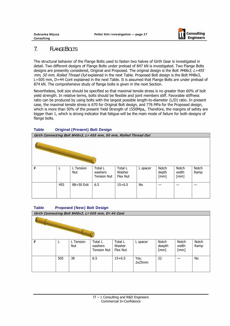
The structural behavior of the Flange Bolts used to fasten two halves of Girth Gear is investigated in detail. Two different designs of Flange Bolts under preload of 847 kN is investigated. Two Flange Bolts designs are presently considered, Original and Proposed. The original design is the Bolt M48x3, L=455 mm, 50 mm, Rolled Thread Out explained in the next Table. Proposed Bolt design is the Bolt M48x3, L=505 mm, D=44 Cont explained in the next Table. It is assumed that Flange Bolts are under preload of 874 kN. The comprehensive study of flange bolts is given in the next Section.
Nevertheless, bolt size should be specified so that maximal tensile stress is no greater than 60% of bolt yield strength. In relative terms, bolts should be flexible and joint members stiff. Favorable stiffness ratio can be produced by using bolts with the largest possible length-to-diameter (L/D) ratio. In present case, the maximal tensile stress is 670 for Original Bolt design, and 776 MPa for the Proposed design, which is more than 50% of the present Yield Strength of 1550Mpa,. Therefore, the margins of safety are bigger than 1, which is strong indicator that fatigue will be the main mode of failure for both designs of flange bolts.
Table Original (Present) Bolt Design Girth Connecting Bolt M48x3, L=455 mm, 50 mm, Rolled Thread Out
F L L Tension
Nut Total L washers Tension Nut
Total L Washer Flex Nut
L spacer Notch depth [mm]
Notch width [mm]
Notch Ramp
455 88+50 Exit 6.5 15+6.5 No — — —
Table Proposed (New) Bolt Design Girth Connecting Bolt M48x3, L=505 mm, D=44 Cont
F L L Tension
Nut Total L washers Tension Nut
Total L Washer Flex Nut
L spacer Notch deepth [mm]
Notch width [mm]
Notch Ramp
505 38 6.5 15+6.5 Yes, 2x25mm
22 — No

Dubravka Mijuca Consulting
Pellet Kiln Investigation — page 28
IT – 1 Consulting and R&D Engineers Commercial In-Confidence
8. STEADY STATE HEAT TRANSFER FE ANALYSIS
The maximum temperature occurs at the interior of the refractory in the amount of 1303 C. It drops down through the thickness of the shell, with minimum value occurring at the feed end.
Maximum temperature occurs in the shell’s sections 4 (bellow girth gear) in the amount of 286C.
Fig. Overall Temperature Field of the Kiln under Normal Operating Conditions

Dubravka Mijuca Consulting
Pellet Kiln Investigation — page 29
IT – 1 Consulting and R&D Engineers Commercial In-Confidence
8.1 REFRACTORY
The purpose of the refractory lining is to insulate the steel shell from the high temperatures inside the kiln, and to protect it from the corrosive properties of the process material. It may consist of refractory bricks or cast refractory concrete, or may be absent in zones of the kiln that are below around 250°C. Presently, it consists of refractory bricks. Refractory changeout is probably the most frequently replaced part of a kiln system. Installation is critical to a long lasting efficient process.
The refractory selected depends upon the temperature inside the kiln and the chemical nature of the material being processed. In some processes, such as cement, the refractory life is prolonged by maintaining a coating of the processed material on the refractory surface.
The thickness of the lining is generally in the range 80 to 300 mm. A typical refractory will be capable of maintaining a temperature drop of 1000°C or more between its hot and cold faces. The shell temperature needs to be maintained below around 350°C in order to protect the steel from damage, and continuous infrared scanners are used to give early warning of "hot-spots" indicative of refractory failure. Presently, the thickness of the lining is 230 mm and it sucessfuly maintains the shell temperature in normal operation bellow 286C. Therefore, present refractory is capable of maintaining a temperature drop of 1069°C or more between its hot and cold faces.
Fig. Temperature Field of the Refractory

Dubravka Mijuca Consulting
Pellet Kiln Investigation — page 30
IT – 1 Consulting and R&D Engineers Commercial In-Confidence
Fig. Temperature Field of the Refractory
8.2 PELLET
Fig. Temperature Field of the Pellet
Dubravka Mijuca Consulting
Pellet Kiln Investigation — page 31
IT – 1 Consulting and R&D Engineers Commercial In-Confidence
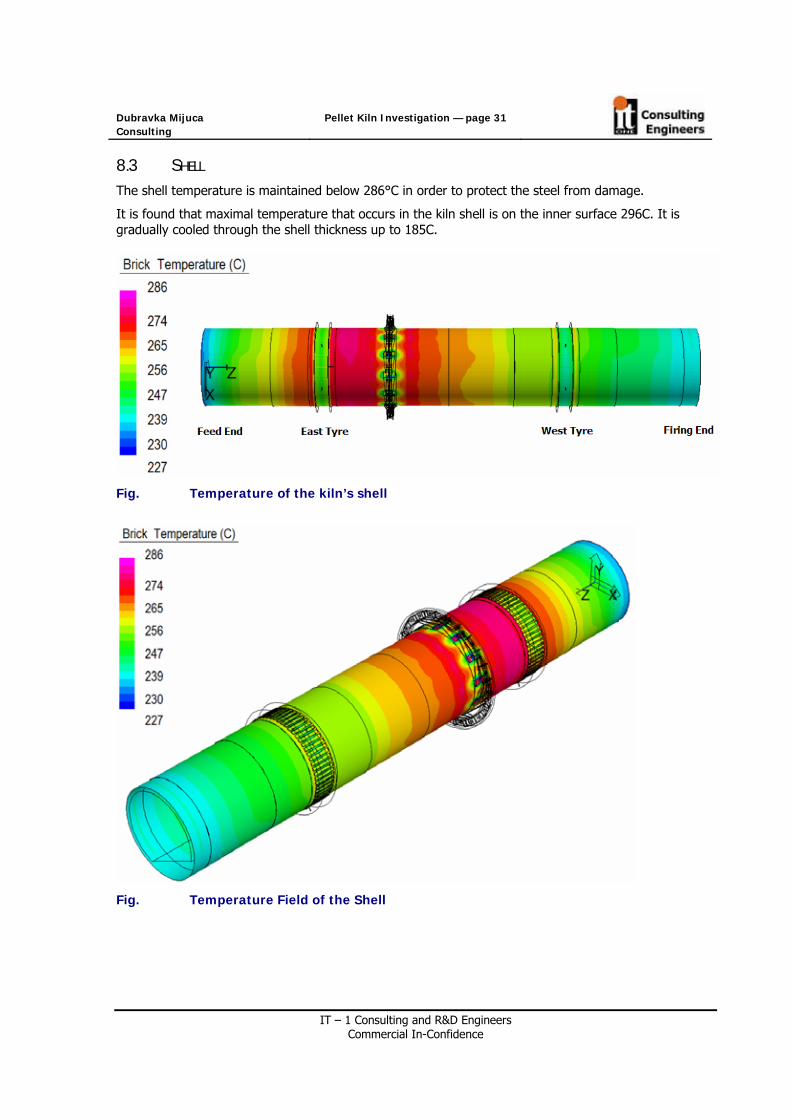
8.3 SHELL
The shell temperature is maintained below 286°C in order to protect the steel from damage.
It is found that maximal temperature that occurs in the kiln shell is on the inner surface 296C. It is gradually cooled through the shell thickness up to 185C.
Fig. Temperature of the kiln’s shell
Fig. Temperature Field of the Shell

Dubravka Mijuca Consulting
Pellet Kiln Investigation — page 32
IT – 1 Consulting and R&D Engineers Commercial In-Confidence
Fig. Temperature Field of the Shell’s Sections 1 and 11
Fig. Temperature Field of the Shell’s Sections 2 and 10

Dubravka Mijuca Consulting
Pellet Kiln Investigation — page 33
IT – 1 Consulting and R&D Engineers Commercial In-Confidence
Fig. Temperature Field of the Shell’s Sections 3 and 8
Fig. Temperature Field of the Shell’s Section 4
Dubravka Mijuca Consulting
Pellet Kiln Investigation — page 34
IT – 1 Consulting and R&D Engineers Commercial In-Confidence
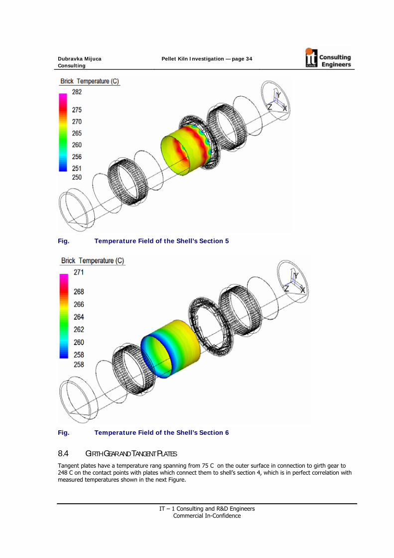
Fig. Temperature Field of the Shell’s Section 5
Fig. Temperature Field of the Shell’s Section 6
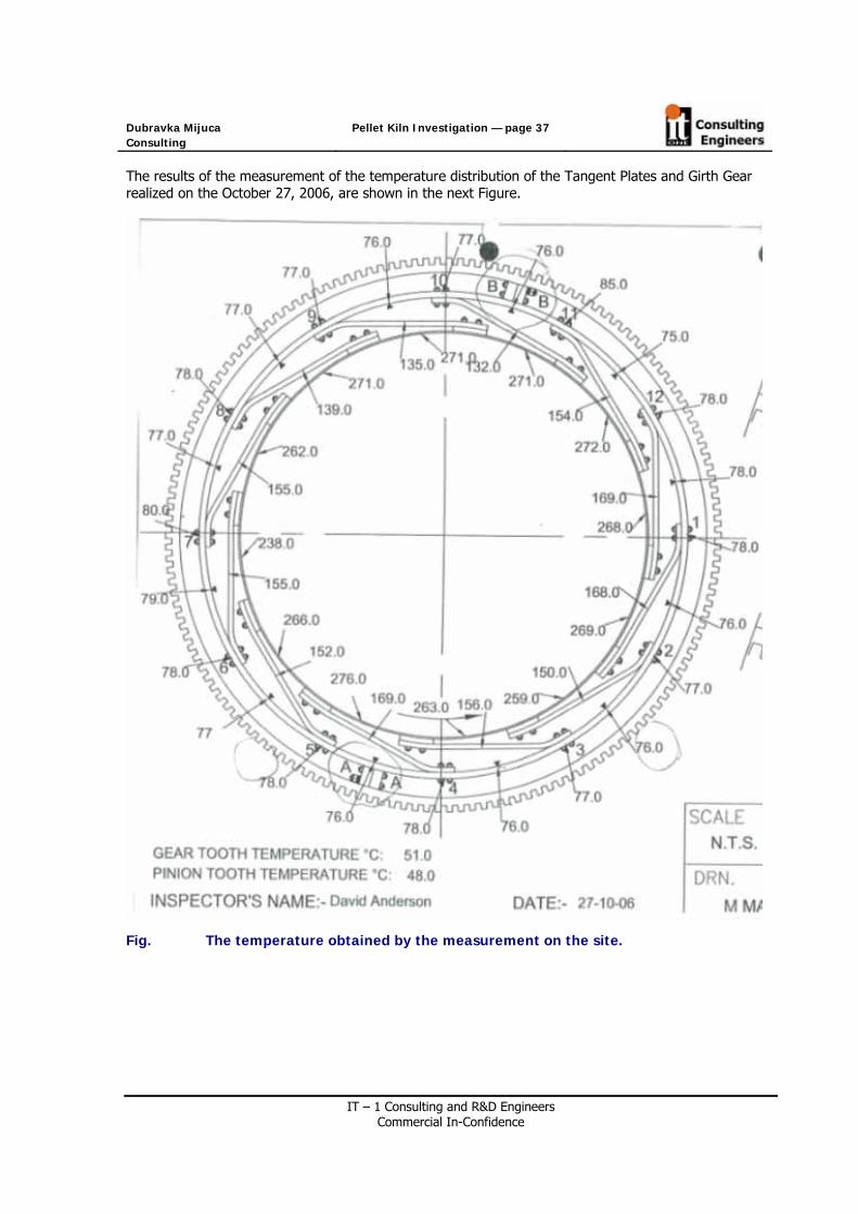
8.4 GIRTH GEAR AND TANGENT PLATES Tangent plates have a temperature rang spanning from 75 C on the outer surface in connection to girth gear to 248 C on the contact points with plates which connect them to shell’s section 4, which is in perfect correlation with measured temperatures shown in the next Figure.

Dubravka Mijuca Consulting
Pellet Kiln Investigation — page 35
IT – 1 Consulting and R&D Engineers Commercial In-Confidence
Fig. Temperatures on Tangent Plates
Fig. Temperature over tangent plates (magnified)

Dubravka Mijuca Consulting
Pellet Kiln Investigation — page 36
IT – 1 Consulting and R&D Engineers Commercial In-Confidence
Girth gear have a temperature rang spanning from 49 C on the outer surface in connection to girth gear to 87 C on the contact points with tangent plates, which is also in perfect correlation with measured temperatures shown in one of the next Figures.
Fig. Temperature distribution over the Girth Gear
Dubravka Mijuca Consulting
Pellet Kiln Investigation — page 37
IT – 1 Consulting and R&D Engineers Commercial In-Confidence
The results of the measurement of the temperature distribution of the Tangent Plates and Girth Gear realized on the October 27, 2006, are shown in the next Figure.
Fig. The temperature obtained by the measurement on the site.

Dubravka Mijuca Consulting
Pellet Kiln Investigation — page 38
IT – 1 Consulting and R&D Engineers Commercial In-Confidence
8.5 TABLES AND DIAGRAMS
Table Temperature of the shell along the kiln Kiln in Normal Operation
Temperature Longitudinal Coordinate [mm] 90 deg 180 deg 270 deg 0 deg
0 235 235 235 235 2499 253 253 253 256 4997 262 262 262 262 6364 268 269 269 270 7731 274 274 274 273 8001 277 277 277 278 8214 262 264 262 265 8712 256 258 256 258 9211 266 268 266 267 9423 282 282 282 281 9693 279 280 279 278 10791 282 282 281 280 11889 278 278 278 278 12544 274 274 274 276 13198 270 269 270 270 13528 268 267 268 268 13603 268 267 268 267 13678 268 267 268 267 14008 267 266 267 266 14084 266 266 266 266 15044 275 275 275 273 16004 269 269 270 270 17923 267 267 267 267 20299 266 266 266 266 22676 259 259 259 259 24043 261 261 261 261 25410 259 259 259 259 25679 268 268 267 266 25892 255 257 255 255 26391 248 250 248 247 26889 255 257 255 254 27102 267 268 267 264 27372 259 259 258 256 28739 253 253 253 253 30105 251 251 250 248 32515 248 248 247 246 34925 240 240 240 240 35522 242 242 242 241 36119 241 241 241 241

Dubravka Mijuca Consulting
Pellet Kiln Investigation — page 39
IT – 1 Consulting and R&D Engineers Commercial In-Confidence
Fig. Temperature of the Shell along the kiln at 90 (blue), 180 (red), 270 (green) and 0 (yellow) degrees for the Kiln in Normal Operation

Dubravka Mijuca Consulting
Pellet Kiln Investigation — page 40
IT – 1 Consulting and R&D Engineers Commercial In-Confidence
9. ELASTOSTATICS RESULTS OF THE KILN IN NORMAL
OPERATION
9.1 DISPLACEMENTS
9.1.1. ELONGATION
Changes in length on heating and cooling typically shoul be around 0.1 to 0.5% of the length. In the present case the kiln elongates for 0.29^ of its original length.
Fig. Elongation

Dubravka Mijuca Consulting
Pellet Kiln Investigation — page 41
IT – 1 Consulting and R&D Engineers Commercial In-Confidence
9.1.2. DEFLECTION OF THE SHELL
Minimal and maximal deflection of the shell are -0.4 and 15 mm, respectively.
Fig. Deflection of the Shell
9.1.3. RADIAL AND TANGENTIAL DISPLACEMENT OF THE KILN
Minimal and maximal radial displacements of the whole kiln are -6.7 and 15.1mm respectively, shown in next Figures. While Minimal and maximal tangential displacements of the whole kiln are -5.3 and 14.3mm.
Fig. Radial displacement of the Kiln

Dubravka Mijuca Consulting
Pellet Kiln Investigation — page 42
IT – 1 Consulting and R&D Engineers Commercial In-Confidence
Fig. Radial displacement of the Kiln
Fig. Tangential displacements of the Kiln

Dubravka Mijuca Consulting
Pellet Kiln Investigation — page 43
IT – 1 Consulting and R&D Engineers Commercial In-Confidence
9.1.4. RADIAL DISPLACEMENT OF THE SHELL
Fig. Radial displacements of the shell

Dubravka Mijuca Consulting
Pellet Kiln Investigation — page 44
IT – 1 Consulting and R&D Engineers Commercial In-Confidence
9.1.5. TANGENTIAL DISPLACEMENT OF THE SHELL
Fig. Tangential displacements of the shell

Dubravka Mijuca Consulting
Pellet Kiln Investigation — page 45
IT – 1 Consulting and R&D Engineers Commercial In-Confidence
9.1.6. RADIAL DISPLACEMENT OF THE SHELL CENTRE SECTIONS
Fig. Rotating Kiln Shell [Philips 2007]
Fig. Present Kiln Rotating Shell Section 7

Dubravka Mijuca Consulting
Pellet Kiln Investigation — page 46
IT – 1 Consulting and R&D Engineers Commercial In-Confidence
9.1.7. RADIAL DISPLACEMENT OF THE FEED END AND THE DISCHARGE END
Fig. The radial displacement of the feed end and discharge end, respectively

Dubravka Mijuca Consulting
Pellet Kiln Investigation — page 47
IT – 1 Consulting and R&D Engineers Commercial In-Confidence
Fig. The radial displacement of the feed end and discharge end, respectively
Diametric difference at (0 and 90, and 180 and 270 degrees):
Feed end: [10.1-(-3.4)]+(10.4-10.5)=14.5-0.1=13.4 [mm]
Discharge end: [8.8-(-0.7)]+(12.1-8.2)=9.5-3.9=5.6 [mm]
It can be seen that radial displacement at feed end is bigger than that at discharge end.

Dubravka Mijuca Consulting
Pellet Kiln Investigation — page 48
IT – 1 Consulting and R&D Engineers Commercial In-Confidence
9.1.8. EXAGGERATED DISPLACEMENTS OF THE SHELL, TANGENT PLATES, GIRTH GEAR AND TYRES
In normal operation the shell has bigger radial displacements than tangent plates, which is for expected for this type of material which are similar, while shell is much wormer than the tangent plates. So, in the next Figure, where displacements are 500 exaggerated, it looks like tangent plates going inwards in to the shell.
Fig. 500 times Exaggerated displacements of the Shell, Girth Gear, Tangent Plates and Tyres in Normal Operation
Fig. 500 times Exaggerated displacements of the Shell section4 and Tangent Plates in Normal Operation

Dubravka Mijuca Consulting
Pellet Kiln Investigation — page 49
IT – 1 Consulting and R&D Engineers Commercial In-Confidence
9.1.9. RADIAL AND TANGENTIAL DISPLACEMENT OF THE GIRTH GEAR
Range of minimal and maximal radial displacements of the Girth Gear is from -6.7mm to 7.9 mm. While, range for tangential displacements of the Girth Gear is from -1.2 mm to 14.3 mm.
Fig. Radial displacement of the Tangent Plats and Girth Gear
Fig. Tangential displacement of the Tangent Plats and Girth Gear

Dubravka Mijuca Consulting
Pellet Kiln Investigation — page 50
IT – 1 Consulting and R&D Engineers Commercial In-Confidence
9.1.10. RADIAL AND TANGENTIAL DISPLACEMENTS OF THE TANGENT PLATS
Minimal and maximal radial displacements of tangent plates are -6.6 an 13.5mm, while tangential displacement is from -3.7mm to 13.5 mm, respectively. It is found that Tangent Plates (see next Section) are successful in amortization of the shell disturbances and that successfully protect Girth Gear. They are fully flexible and enable minimal relative displacements between Girth Gear and Kiln Shell. Measuring the relative displacement between kiln and girth gear, it is found that present design of Tangent Plates successfully amortizes influence of shell displacement on the displacement of the Girth Gear, and vice versa. Namely, Girth Gear is heavy and tends to fall on the shell, while when hot the shell expands.
Fig. Radial displacement of Tangent Plates.
Fig. Tangential displacement of Tangent Plates

Dubravka Mijuca Consulting
Pellet Kiln Investigation — page 51
IT – 1 Consulting and R&D Engineers Commercial In-Confidence
9.1.11. RADIAL AND TANGENTIAL DISPLACEMENT OF THE TYRE Radial displacements of the Riding Rings (Tyres) are from -2.7 to 14.1mm, while tangential are from -4.2 to 12.3 mm.
Fig. Radial displacement of the Tyres
Fig. Tangential displacement of the Tyres

Dubravka Mijuca Consulting
Pellet Kiln Investigation — page 52
IT – 1 Consulting and R&D Engineers Commercial In-Confidence
9.1.12. RADIAL DISPLACEMENT OF THE SHELL BELLOW TYRE
In the upper quadrant, where the shell is not in contact with the tire (applies to non fixed tire designs only) the critical shell parameter is deflection rather than stress. This is commonly referred to as shell ovality or shell flexing.
The Tyre seats on Filler Bar System bolted on the shell. Filler Bars can become worn over time, which is caused by riding ring slip or "creep". As filler bar wear increases, the amount of creep also increases. This condition results in excessive clearance between the riding ring and filler bars, which will create high ovality. It is important that filler bars reduce high ovality and shell stresses.
Ovality is defined as the difference in length between the horizontal and vertical axis of the kiln due to elastic deformation and is commonly expressed as a percentage of the nominal inside diameter of the kiln shell. Excessive ovality of the kiln shell can have adverse effects on the life of the brick lining due to the pinching at the inside and outside diameters of the lining. If premature failure of the kiln brick lining occurs due to ovality, it would most likely occur first at the tyres (riding rings) where ovality is the greatest. Failure modes that can be associated with high ovality include:
• Premature mechanical refractory failure • Overheating and/or failure of carrying mechanism bearings • Shell cracking • Weld cracking
As the tyre itself continuously changes shape during rotation, its ovality must be calculated and limited. Since the shell is not in contact with the tire in the upper quadrant its "ovality" will be approximately double that of the tire. In the present case shell ovality is maximally bigger 30% than that of the tyre., which is very good because the high ovality is one common cause of premature refractory failures.
Fig. Radial displacement of the shell bellow tyre

Dubravka Mijuca Consulting
Pellet Kiln Investigation — page 53
IT – 1 Consulting and R&D Engineers Commercial In-Confidence
9.1.13. RELATIVE DISPLACEMENT BETWEEN SHELL AND UPHILL TYRE
Relative displacement between uphill tyre and the shell below it changes from 0.1 to 3mm.
Ovality of the shell is [12.2-(-1.9)]/[12.8-(12.7)]=14.1/0.1=14.1
Ovality of the Tyre is [ 9.4–(-2.4)]/[12.2.-10.7]=11.8/1.5=7.86
Fig. Radial displacement between Uphill Tyre and shell bellow it - Ovality

Dubravka Mijuca Consulting
Pellet Kiln Investigation — page 54
IT – 1 Consulting and R&D Engineers Commercial In-Confidence
Table. Relative displacement between Shell and Uphill Tyre
Angle Part Point Radial Displacement [mm] Relative difference [mm]
Shell outer Radius 1 12.2 0 /up/ Uphill Tyre Inside Radius 2 9.4
2.8
Shell outer Radius 3 12.8 30 Uphill Tyre Inside Radius 4 9.8
3.0
Shell outer Radius 5 13.6 60 Uphill Tyre Inside Radius 6 11.2
2.4
Shell outer Radius 7 12.8 90 /left/ Uphill Tyre Inside Radius 8 10.7
2.1
Shell outer Radius 9 6.1 120 Uphill Tyre Inside Radius 10 6.0
0.1
Shell outer Radius 11 0.1 150 Uphill Tyre Inside Radius 12 -0.1
0.2
Shell outer Radius 13 -1.9 180 /down/ Uphill Tyre Inside Radius 14 -2.4
0.5
Shell outer Radius 15 -0.2 210 Uphill Tyre Inside Radius 16 -0.3
0.1
Shell outer Radius 17 5.8 240 Uphill Tyre Inside Radius 18 5.7
0.3
Shell outer Radius 19 12.7 270 /right/ Uphill Tyre Inside Radius 20 12.2
0.5
Shell outer Radius 21 14.3 300 Uphill Tyre Inside Radius 22 13.0
1.3
Shell outer Radius 23 13.2 330 Uphill Tyre Inside Radius 24 11.0
2.2
The shell ovality should not exceed 10% of the shell diameter in meters. For the present 36.1188m kiln with diameter of 5.84m radius, the ovality should not exceed 0.58%, which is 0.0338m, that is, 33mm. Therefore, present kiln design has allowable ovality of the shell.
The relative displacement between Shell and uphill Tyre for proposed solution of the Flange Bolts is investigated in the present section. This relative displacement is referred as Ovality in the literature. The position of Tyre shown on the Figure *, is observed. The relative displacements between Shell and Tyre are shown in the Table *.

Dubravka Mijuca Consulting
Pellet Kiln Investigation — page 55
IT – 1 Consulting and R&D Engineers Commercial In-Confidence
9.1.14. RELATIVE DISPLACEMENT BETWEEN SHELL AND GIRTH GEAR
The relative displacement between Shell and Girth Gear for proposed solution of the Flange Bolts is investigated in the present section. The position of Two Halves of Girth Gear shown on the Figure *, is presently investigated. The relative displacements between Shell and Girth Gear are shown in the Figure *.
Fig. Position of Girth Gear
Fig. The relative displacement between Shell and Girth Gear

Dubravka Mijuca Consulting
Pellet Kiln Investigation — page 56
IT – 1 Consulting and R&D Engineers Commercial In-Confidence
Table The relative radial displacement between Shell and Girth Gear, Tangent Plate Amortization
Angle Part Point Radial Displacement [mm] Relative difference [mm]
Shell outer Radius 1 12.0 15 Girth Gear Inside Radius 2 7.1
4.9
Shell outer Radius 3 12.8 45 Girth Gear Inside Radius 4 6.1
6.7
Shell outer Radius 5 12.2 75 Girth Gear Inside Radius 6 4.4
7.8
Shell outer Radius 7 8.2 105 Girth Gear Inside Radius 8 1.0
7.2
Shell outer Radius 9 2.3 135 Girth Gear Inside Radius 10 -3.3
5.6
Shell outer Radius 11 -1.5 165 Girth Gear Inside Radius 12 -6.3
4.8
Shell outer Radius 13 -1.0 195 Girth Gear Inside Radius 14 -6.4
5
Shell outer Radius 15 3.0 225 Girth Gear Inside Radius 16 -3.5
7.5
Shell outer Radius 17 8.2 255 Girth Gear Inside Radius 18 1.1
7.1
Shell outer Radius 19 12.1 285 Girth Gear Inside Radius 20 5.0
7.1
Shell outer Radius 21 13.0 315 Girth Gear Inside Radius 22 7.1
5.9
Shell outer Radius 23 12.1 345 Girth Gear Inside Radius 24 7.5

Dubravka Mijuca Consulting
Pellet Kiln Investigation — page 57
IT – 1 Consulting and R&D Engineers Commercial In-Confidence
9.2 STRESSES
The allowable range for the stress in the kiln is in the next limits: Heavy plate shear stress < 2.76 MPa Flanking plate bending stress < 15 MPa Balance shell ( next to flanking plate ) bending stress < 20 MPa Balance shell ( at mid span ) bending stress < 15 MPa
9.2.1. VON MISES STRESS OF THE SHELL
Von Mises Stresses in the shell are mostly bellow 9 MPa.
Fig. Von Mises Stresses of the Shell

Dubravka Mijuca Consulting
Pellet Kiln Investigation — page 58
IT – 1 Consulting and R&D Engineers Commercial In-Confidence
9.2.2. RADIAL STRESS OF THE SHELL
Radial stress in the shell is in range from [-2.4, 1.7] MPa, but mostly these stresses are around -0.9 MPa
Fig. Shell Radial Stresses

Dubravka Mijuca Consulting
Pellet Kiln Investigation — page 59
IT – 1 Consulting and R&D Engineers Commercial In-Confidence
9.2.3. TANGENTIAL STRESS OF THE SHELL
The bending stress in the shell undergoing 100% reversal with each turns of the shell, and therefore fatigue taking its toll in the long run. Most likely it takes more than simple fatigue; things like manufacturing/installation defects, unusual loading conditions, changing to higher speeds, higher than expected shell temperatures, bad alignment and excessive shell flexing etc. etc. to cause failures.
The minimal and maximal tangential bending stresses of the shell outside girth gear and tyres, are -25.3MPa and 21.2 MPa, respectively. Nevertheless, these are vary localized extremes. The most part of the shell have tangential stress in range from -2.0 MPa to 3.8MPa.
The tangential bending stress of the shell under the tire is usually not calculated. It would be a very low number since it is almost continuously supported by the tire for most of the circumference around the lower 270 degrees. Presently, the tangential bending stress of the shell under the tire is about -2MPa.
Fig. Tangential bending stress of the shell except tyres and girth gear

Dubravka Mijuca Consulting
Pellet Kiln Investigation — page 60
IT – 1 Consulting and R&D Engineers Commercial In-Confidence
From the next figure it could bee seen that maximal bending stress occurs where shell not anymore seats on the Tyre plates. That is where the gap between Tyre and the Shell starts to form. Nevertheless, actual stress at that location is likely to be lesser than presently calculated 37.9MPa, because even plates bellow tyre are not welded to the shell (as in present FE modeling), but shell just slides over it. So, this maximal value is excluded from analysis.
Fig. Tangential bending stress of the shell

Dubravka Mijuca Consulting
Pellet Kiln Investigation — page 61
IT – 1 Consulting and R&D Engineers Commercial In-Confidence
Fig. Bending Stress in the Shell in the Range from [-10.10] MPa

Dubravka Mijuca Consulting
Pellet Kiln Investigation — page 62
IT – 1 Consulting and R&D Engineers Commercial In-Confidence
The tangential bending stress of the section 4 bellow Girth Gear are mostly in rang from -0.5MPa to -6.8, but increasing in the vicinity of contact with tangent plates, where it is about 20MPa. Tangential stresses at the contact between sections 3 and 4 are on the other hand compressive and they are about 20MPa.
Fig. Tangential bending stress of the shell under girth gear
Fig. Detail of the tangential stresses at the contact between sections 3 and 4.

Dubravka Mijuca Consulting
Pellet Kiln Investigation — page 63
IT – 1 Consulting and R&D Engineers Commercial In-Confidence
In the area of the shell under the tire the bending stress would only be induced by changes of curvature of the tire which are insignificant with respect to tangential shell stress (see next Figure). Because the maximum stress is usually at the supports the shell plate thickness then also increases as we approach each tire and presently also has maximum thickness directly under the tire.
Fig. Tangential bending stress of the shell under the tire
Fig. Tangential Stress of the Filler Bars Bellow Tyres
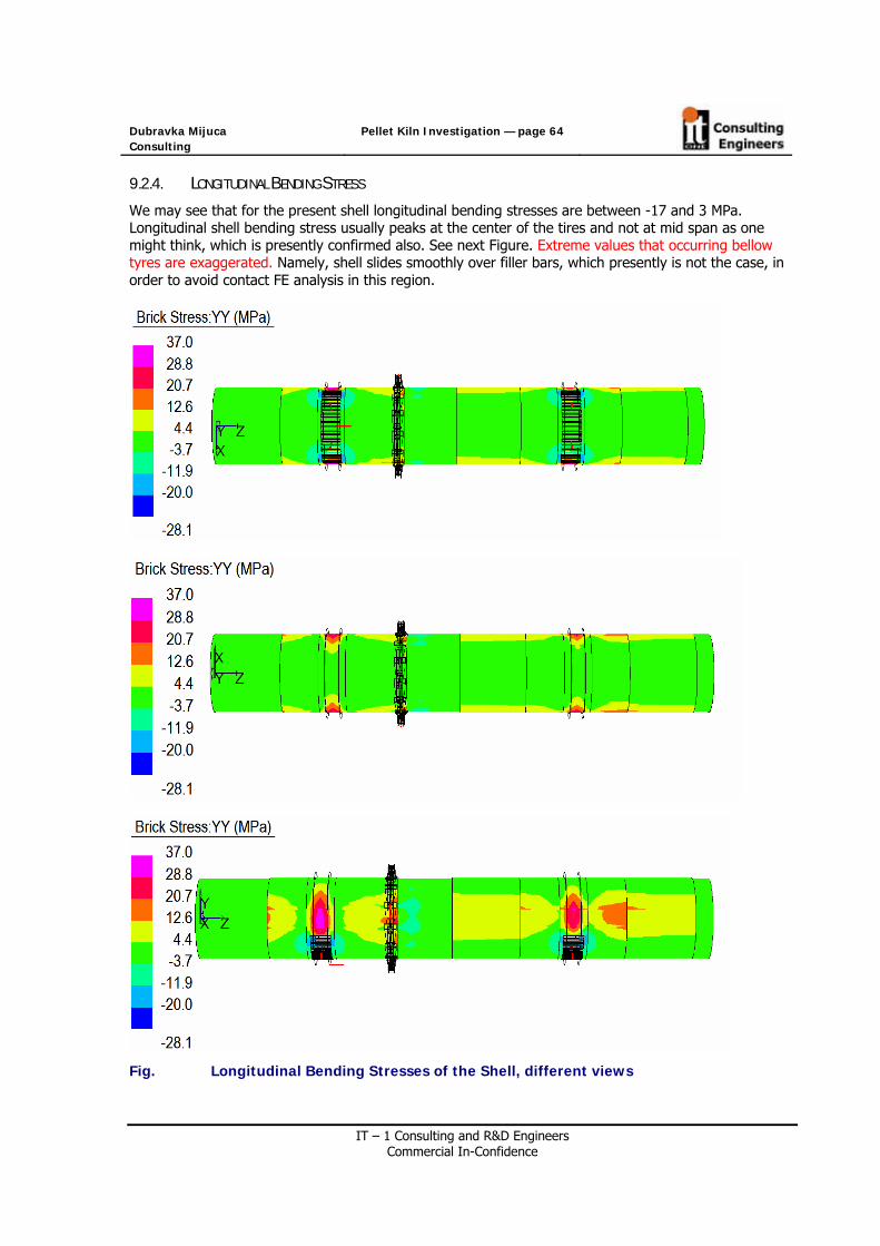
Dubravka Mijuca Consulting
Pellet Kiln Investigation — page 64
IT – 1 Consulting and R&D Engineers Commercial In-Confidence
9.2.4. LONGITUDINAL BENDING STRESS
We may see that for the present shell longitudinal bending stresses are between -17 and 3 MPa. Longitudinal shell bending stress usually peaks at the center of the tires and not at mid span as one might think, which is presently confirmed also. See next Figure. Extreme values that occurring bellow tyres are exaggerated. Namely, shell slides smoothly over filler bars, which presently is not the case, in order to avoid contact FE analysis in this region.
Fig. Longitudinal Bending Stresses of the Shell, different views

Dubravka Mijuca Consulting
Pellet Kiln Investigation — page 65
IT – 1 Consulting and R&D Engineers Commercial In-Confidence
9.2.5. GIRTH GEAR STRESSES
Over time main kiln gear wear can cause gear teeth misalignment. When this happens wear on gear is accelerated. For this reason, gears are sometimes reversed or replaced. Gear repair can require cutting the kiln. Sometimes gears are fabricated in pieces so kiln separation is not required. Improper installation can cause kiln damage or improper operation.
Presently, the Gear consists of two halves, which are connected by the 4 Flange and 4 Positioning Bolts. The present – Original bolt design suffers from premature failure. One of the main goals of the present investigation is to find the reason for it.
In girth gear average values of radial stress are -0.5MPa, except at the contact with washers/spacers around Flange Bolts where this value is much higher and compressive, and around Positioning Bolts where this value is in tension. The average tangential stresses of Girth Gear are from -17.9 MPa to 7MPa.
Fig. Girth Gear Radial stress /Maximum Values bellow Washers/

Dubravka Mijuca Consulting
Pellet Kiln Investigation — page 66
IT – 1 Consulting and R&D Engineers Commercial In-Confidence
Fig. Girth Gear Tangential stress /Maximum Values bellow Washers/
Fig. Girth Gear Von Mises Stresses/Maximum Values bellow Washers/

Dubravka Mijuca Consulting
Pellet Kiln Investigation — page 67
IT – 1 Consulting and R&D Engineers Commercial In-Confidence
9.2.6. TANGENT PLATES STRESSES
The average tangential stress of the tangent plates is about 10MPa. While average radial stress of the tangent plates are from -5 to 5 MPa. The extreme value occurs at the contact between girth gear where the tangential stress is compressive and about -200MPa, and radial stress is about -50 MPa. Average rang for Von Mises Stresses are from 1 to 22 MPa.
Fig. Tangent Plates Circumferential Stress

Dubravka Mijuca Consulting
Pellet Kiln Investigation — page 68
IT – 1 Consulting and R&D Engineers Commercial In-Confidence
Fig. Tangent Plates Radial Stresses

Dubravka Mijuca Consulting
Pellet Kiln Investigation — page 69
IT – 1 Consulting and R&D Engineers Commercial In-Confidence
Fig. Tangent Plates Von Mises Circumferential stress

Dubravka Mijuca Consulting
Pellet Kiln Investigation — page 70
IT – 1 Consulting and R&D Engineers Commercial In-Confidence
9.3 REACTIONS AT THE SUPPORTS
The reaction forces will be monitored at the restraints of the kiln’s model. There is only 5 restrained nodes in the kiln, 2 per each tyre on 30 degrees from downside vertical axe, and one at the uphill tyre on the place of the axial thrust roller to prevent kiln to slide down due to its inclination of the 2.9 degrees. The total mass of of the kiln is 883744kg, which is total weight of 8669529 N.
If the torque from the eccentricity of the pellets (pellet loading) is balanced with the forces 231.989kN at the contact with the pinions, and if radial external forces of 84.4kN are applied also at these points, the next reaction forces are obtained at the supports (contact of tyres with support rollers).
Reaction force at contact with uphill left tyre is 2037506N, with uphill right tyre is 2618348N, with downhill left tyre is 2482083N and with downhill right tyre is 2704425N.
Fig. Reaction in the Kiln with Pellets where Bolts are on 0 and 90 degrees
Node Fx [N] Fy [N] Uphill Left Tyre 1018528 1764143 Uphill Right Tyre -1309174 2267556 Downhill Left Tyre 1241042 2149547 Downhill Right Tyre -1352212 2342100 Sum 8523346

Dubravka Mijuca Consulting
Pellet Kiln Investigation — page 71
IT – 1 Consulting and R&D Engineers Commercial In-Confidence
If tangential force of 232 kN that balances the torque from the eccentricity of the pellets is applied only at 90 degrees, we obtain the symmetric reactions at supports:
Node Fx [N] Fy [N] Uphill Left Tyre 1.29127E+6 2.23655E+6 Uphill Right Tyre -1.29127E+6 2.23655E+6 Downhill Left Tyre 1.34537E+6 2.33024E+6 Downhill Right Tyre -1.34537E+6 2.33024E+6

Dubravka Mijuca Consulting
Pellet Kiln Investigation — page 72
IT – 1 Consulting and R&D Engineers Commercial In-Confidence
9.4 TABLES AND DIAGRAMS
Fig. Radial displacement stress along kiln at different angles.
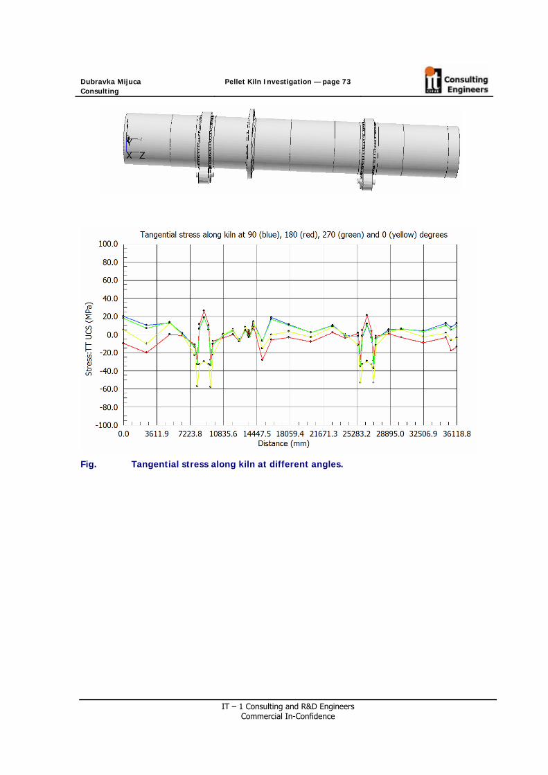
Dubravka Mijuca Consulting
Pellet Kiln Investigation — page 73
IT – 1 Consulting and R&D Engineers Commercial In-Confidence
Fig. Tangential stress along kiln at different angles.

Dubravka Mijuca Consulting
Pellet Kiln Investigation — page 74
IT – 1 Consulting and R&D Engineers Commercial In-Confidence
Table Radial displacement and Tangential stresses of the Kiln Kiln in Normal
Operation
Radial displacement [mm] Tangential Stress [MPa] Longitudinal Coordinate
[mm] 90 deg 180
deg 270 deg 0 deg 90 deg 180
deg 270 deg 0 deg
0 10.1 10.1 10.5 -3.4 20.2 -9.7 17.7 5.32498.72 10.8 10.8 11.3 -2.8 10.2 -19.9 7.1 -10.14997.45 11.3 11.3 12 -2.4 12.9 0 13.3 12.36364.29 11.5 11.6 12.2 -2.3 1.4 -1 0.4 -0.27731.12 11.5 11.7 12.3 -2.4 -13.9 -11.2 -13.7 -22.9
8001 11.5 11.7 12.3 -2.6 -32.7 -26.7 -32.7 -578213.72 11.4 11.7 12.2 -2.7 6.4 11.4 6.2 -33.18712.2 11.4 11.7 12.1 -2.9 18.8 26.3 18.5 -30.1
9210.67 11.5 11.9 12.2 -2.6 5.6 10.3 5.2 -32.99423.4 11.5 12 12.2 -2.3 -33.6 -27.9 -34 -57.9
9693.27 11.6 12.1 12.3 -2.1 -10.5 -7.2 -11.1 -22.610791.03 11.6 12.4 12.1 -1.5 -0.8 -3.8 -0.9 0.311339.91 11.3 12.4 11.7 -1.4 4.2 0.1 4.2 5.711888.79 11 12.3 11.3 -1.5 -5.6 -7.8 -5.9 -7.312543.54 10.6 12 10.8 -1.7 4.6 5 4 813198.29 10.5 11.9 10.5 -1.8 -0.7 1.7 -0.8 5.113528.29 10.5 11.9 10.5 -1.8 -3 -0.2 -3.3 313603.29 10.5 11.9 10.5 -1.8 -1.3 0.6 -2 3.913678.29 10.6 12 10.5 -1.7 7.1 5.5 5.9 8.714008.29 10.6 12 10.5 -1.7 12.5 8.7 11 14.3
14084.3 10.9 12.2 10.7 -1.4 -6.8 -28.1 -7 -15.215043.94 11.1 12.1 10.7 -1.3 19 -6 16.7 -0.216003.59 11.3 11.7 10.6 -1.4 10.8 -3.3 10.3 3.117922.87 11.7 11.1 10.8 -1.7 2.3 -8.2 2 -2.920299.36 12.1 10.4 11.1 -2 10.2 2.1 9.9 8.322675.85 12.4 10.1 11.4 -2.1 -1 -4.1 -1.3 0.524042.69 12.7 9.9 11.5 -2.3 -2 1.6 -2.3 -11.825409.52 12.7 9.8 11.5 -2.5 -35.5 -27.3 -34.8 -53.3
25679.4 12.7 9.7 11.5 -2.6 -2.4 4.9 -1.5 -32.925892.13 12.7 9.6 11.4 -2.8 10.3 21.1 11.5 -29.4
26390.6 12.8 9.6 11.4 -2.6 -3.5 3.8 -2.6 -33.226889.07 12.8 9.6 11.5 -2.5 -37.4 -29.2 -36.5 -53.3
27101.8 12.8 9.6 11.4 -2.3 -4.6 -1.7 -4.4 -11.927371.67 12.7 9.4 11 -2 5.3 0.8 4 2.628738.51 12.5 9.2 10.5 -1.9 6.3 -3.3 6.6 5.630105.35 12.2 9 9.6 -1.4 3.9 -9.2 3.3 -2.632515.17 11.8 8.9 8.6 -1 12.3 -3.1 10 1.5
34925 11.8 8.8 8.4 -0.8 8 -17.7 5 -635521.9 11.8 8.9 8.2 -0.7 12.3 -13.4 8.6 -3.636118.8
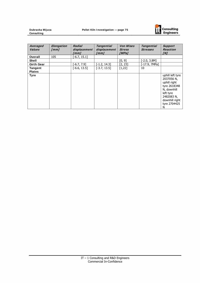
Dubravka Mijuca Consulting
Pellet Kiln Investigation — page 75
IT – 1 Consulting and R&D Engineers Commercial In-Confidence
Averaged Values
Elongation [mm]
Radial displacement[mm]
Tangential displacement[mm]
Von Mises Stress [MPa]
Tangential Stresses
Support Reaction [N]
Overall 105 [-6.7, 15.1] Shell [0, 9] [-2.0, 3.8M] Girth Gear [-6.7, 7.9] [-1.2, 14.3] [2, 23] [-17.9, 7MPa] Tangent Plates
[-6.6, 13.5] [-3.7, 13.5] [1,22] 10
Tyre uphill left tyre 2037056 N, uphill right tyre 2618348 N, downhill left tyre 2482083 N, downhill right tyre 2704425 N

Dubravka Mijuca Consulting
Pellet Kiln Investigation — page 76
IT – 1 Consulting and R&D Engineers Commercial In-Confidence
9.5 STRESS CALCULATION OF FLANGE BOLTS
In the present section stress calculation of Flange Bolts under normal operating conditions of the kiln is investigated in detail.
When a load is applied to a joint containing a tightened bolt it does not sustain the full effect of the load but usually only a small part of it. An understanding of why the bolt does not sustain the full effect of the applied load is fundamental to the subject. In the case of this fastener no significant load increase would be sustained by the fastener until the applied load exceeded the fastener's preload. (Preload is the term used for a bolt's clamp force)
The behavior of the Flange Bolts and joint between two halves of the Girth Gear is observed. The materially and geometrically nonlinear contact finite element analysis was conducted in order to properly trace the closing and opening of the joint.
A series of analyses, where Flange Bolts are located at different orientations araund the kiln are simulated, to determine the stress in the bolts as the kiln rotates through different positions.
The analysis is performed for both bolts design, Original M48x3 L=455 mm D=50 mm Rolled Thread Out and M48X3 L=505 MM D=44 CONTINUOUS, shown in next Table. The results are compared.
Table Original (Present) Bolt Design Girth Connecting Bolt M48x3, L=455 mm, 50 mm, Rolled Thread Out
F L L Tension
Nut Total L washers Tension Nut
Total L Washer Flex Nut
L spacer Notch depth [mm]
Notch width [mm]
Notch Ramp
455 88+50 Exit 6.5 15+6.5 No — — —
Table Proposed (New) Bolt Design Girth Connecting Bolt M48x3, L=505 mm, D=44 Cont
F L L Tension
Nut Total L washers Tension Nut
Total L Washer Flex Nut
L spacer Notch deepth [mm]
Notch width [mm]
Notch Ramp
505 38 6.5 15+6.5 Yes, 2x25mm
22 — No
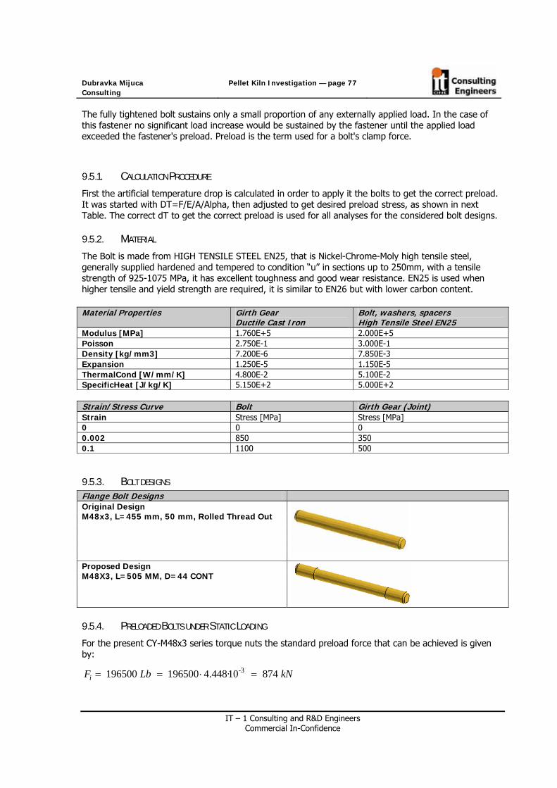
Dubravka Mijuca Consulting
Pellet Kiln Investigation — page 77
IT – 1 Consulting and R&D Engineers Commercial In-Confidence
The fully tightened bolt sustains only a small proportion of any externally applied load. In the case of this fastener no significant load increase would be sustained by the fastener until the applied load exceeded the fastener's preload. Preload is the term used for a bolt's clamp force.
9.5.1. CALCULATION PROCEDURE
First the artificial temperature drop is calculated in order to apply it the bolts to get the correct preload. It was started with DT=F/E/A/Alpha, then adjusted to get desired preload stress, as shown in next Table. The correct dT to get the correct preload is used for all analyses for the considered bolt designs.
9.5.2. MATERIAL
The Bolt is made from HIGH TENSILE STEEL EN25, that is Nickel-Chrome-Moly high tensile steel, generally supplied hardened and tempered to condition “u” in sections up to 250mm, with a tensile strength of 925-1075 MPa, it has excellent toughness and good wear resistance. EN25 is used when higher tensile and yield strength are required, it is similar to EN26 but with lower carbon content. Material Properties Girth Gear
Ductile Cast Iron Bolt, washers, spacers High Tensile Steel EN25
Modulus [MPa] 1.760E+5 2.000E+5 Poisson 2.750E-1 3.000E-1 Density [kg/mm3] 7.200E-6 7.850E-3 Expansion 1.250E-5 1.150E-5 ThermalCond [W/mm/K] 4.800E-2 5.100E-2 SpecificHeat [J/kg/K] 5.150E+2 5.000E+2 Strain/Stress Curve Bolt Girth Gear (Joint) Strain Stress [MPa] Stress [MPa] 0 0 0 0.002 850 350 0.1 1100 500
9.5.3. BOLT DESIGNS Flange Bolt Designs Original Design M48x3, L=455 mm, 50 mm, Rolled Thread Out
Proposed Design M48X3, L=505 MM, D=44 CONT
9.5.4. PRELOADED BOLTS UNDER STATIC LOADING
For the present CY-M48x3 series torque nuts the standard preload force that can be achieved is given by:
-3 196500 196500 4.448·10 874 iF Lb kN= = ⋅ =

Dubravka Mijuca Consulting
Pellet Kiln Investigation — page 78
IT – 1 Consulting and R&D Engineers Commercial In-Confidence
9.5.5. EXTERNAL LOADING
The tangential force of 232 kN that balances the torque from the eccentricity of the pellets is applied at the contact points of girth gear with a pinion. In addition, a radial force (towards the centre of the kiln) of 232x Tan 20 = 84.4 kN at each pinion location is added. The friction is very small due to the design of rollers (floating on an oil film), so it is ignored.
9.5.6. TEMPERATURE OF THE BOLT
Fig. Temperature of the Flange Bolt during normal operation of the kiln.
9.5.7. POSITIONS OF GIRTH GEAR EXAMINED
Due to the symmetry of geometry the 6 position of girth gear during the rotation are examined, shown in next Figures
Position 0: Bolts at 0 and 180 degrees Position 1: Bolts at 30 and 210 degrees

Dubravka Mijuca Consulting
Pellet Kiln Investigation — page 79
IT – 1 Consulting and R&D Engineers Commercial In-Confidence
Position 2: Bolts at 60 and 240 degrees Position 3: Bolts at 90 and 270 degrees
Position 4: Bolts at 120 and 300 degrees Position 5: Bolts at 150 and 330 degrees
Fig. The 6 positions of Girth Gear where stress behavior of the Flange Bolts are
examined

Dubravka Mijuca Consulting
Pellet Kiln Investigation — page 80
IT – 1 Consulting and R&D Engineers Commercial In-Confidence
9.5.8. THEORY OF THE PRELOADED BOLTED JOINTS
At (a), there are no forces in the joint.
At b), the nut has been tightened up, producing a tensile force Fi in the bolt. The bolt is stretched by the amount (x2 – x1) given by Fi/kb. The members have been compressed by the amount δxi giving rise to a compressive force Fc given by Fc/km. From equilibrium, we also have Fc = - Fi.
At c), external force Fe is applied. This acts to pull the members apart by amount δxe. The bolt is stretched by an additional amount δxe and the members relax by the same amount. The bolt force increases and the member force decreases. We now find that Fb > Fi and Fc < Fi. From equilibrium we get Fb = Fe + |Fc|.
When External load is applied it tends to separate the members.

Dubravka Mijuca Consulting
Pellet Kiln Investigation — page 81
IT – 1 Consulting and R&D Engineers Commercial In-Confidence
9.5.9. BOLT DESIGN M48X3, L=455 MM, 50 MM, ROLLED THREAD OUT
The initial preload is simulated as a drop in temperature in bolt volume under the joint. The temperature drop calculation to apply to get the correct preload is explained in the next Table.
Table Calculation of the temperature drop in the original Flange Bolt Calculation of the temperature drop in the bolt to obtained correct preload force F PI 3.141592654 r 0.024m radius of the shaft of the bolt F 874000N Alpha 1.15E-5 E 2E11Pa A =r**2*PI 1.809557E-03 S=F/A 483MPa The stress at the initial preload dT=-F/(E*A*Alpha) -210C dT scaled -212 C Scaled temperature to obtain correct stress at the initial
preload Additional drop -0.01mm/290mm/1.15E-5=
-3C The temperature drop that is assign to the bolts is increased to create the additional preload to shorten the bolts by the amount of the gap. It is equal [gap/(bolt length)/alpha].
Temperature of the bolt in the kiln
-133C-3C=-136C If ambient temperature is 25C and temperature of the bolt 75C, and initial gap between joint surface is 0.01mm.
The difference among clamp force Fc and preload Force Fc should be zero, which is presently confirmed giving the difference in small value of 2kN, which can be seen from next figures:
Fig. Original Flange Bolts design – clamp stress and compressive clamp force Fc in joint

Dubravka Mijuca Consulting
Pellet Kiln Investigation — page 82
IT – 1 Consulting and R&D Engineers Commercial In-Confidence
Fig. Original Flange Bolts design – Preload stress and Preload force Fi in bolt
Fig. Original Flange Bolts design – Difference Fi-Fc

Dubravka Mijuca Consulting
Pellet Kiln Investigation — page 83
IT – 1 Consulting and R&D Engineers Commercial In-Confidence
Let us investigate Position 3 for the Original Flange Bolts Design, shown in the next Figure, where bolts are on 90 and 270 degrees. We may see that on 90 degrees relief closing from 2mm to 1.95 mm, while outside points opens from 0.01mm (initial gap) to 0.082 mm.
Fig. Position 3, displacement magnified 100 times to real one.

Dubravka Mijuca Consulting
Pellet Kiln Investigation — page 84
IT – 1 Consulting and R&D Engineers Commercial In-Confidence
9.5.10. BOLT DESIGN M48X3, L=505 MM, D=44 CONT
The initial preload is simulated as a drop in temperature in bolt volume under the joint. The temperature drop calculation to get the correct preload for FE simulation is explained in the next Table.
Table Calculation of the Flange Bolt preload Calculation of the temperature drop in the bolt to obtained correct preload force F PI 3.141592654 r 0.022m F 874000N Alpha 1.15E-5 E 2E11Pa A =r**2*PI 1.520531E-03m2 s=F/A 575MPa The stress at the initial preload Ta 25C Ambient temperature dT=F/(E*A*Alpha) -250C dT scaled -265C Scaled temperature to obtain correct stress at the
initial preload Additional drop -0.01mm/(290mm+50mm)/
1.15E-5/C=-2.55C=3C The temperature drop that is assign to the bolts is increased to create the additional preload to shorten the bolts by the amount of the gap. It is equal [gap/(bolt length)/alpha].
Temperature of the bolt in the kiln
-186.5-3C=-189.5C If ambient temperature is 25C and temperature of the bolt 75C, and initial gap between joint surface is 0.01mm.
he difference among clamp force Fc and preload Force Fc should be zero, which is presently confirmed giving the difference in small value of 0.5kN, which can be seen from next figures:
Fig. Original Flange Bolts design – clamp stress and compressive clamp force Fc in joint

Dubravka Mijuca Consulting
Pellet Kiln Investigation — page 85
IT – 1 Consulting and R&D Engineers Commercial In-Confidence
Fig. Original Flange Bolts design – Preload stress and Preload force Fi in bolt
Fig. Original Flange Bolts design – Difference Fi-Fc

Dubravka Mijuca Consulting
Pellet Kiln Investigation — page 86
IT – 1 Consulting and R&D Engineers Commercial In-Confidence
9.5.11. STRESSES AT CENTRE OF THE FLANGE BOLTS
For both bolts designs preload force is 874kN. Nevertheless, due to the difference in the radius of the bolts preload stresses are different. The Existing Bolt design has initial preload stress of 483MPa, while proposed Bolt design has initial preload stress of 575MPa. In the kiln under normal operating conditions stress in the bolts changes to the values given in the next Table, where with yellow position maximal stress is shown, while with green the one with minimum stress:
Table Stress at Centre of Flange Bolts during rotation of the kiln KILN IN BREAKING IN NORMAL OPERATION
Longitudinal Stress at Centre of the Flange Bolts [MPa] /looking from the discharge end/
ORIGINAL DESIGN A=1.809557E-03 m2
Bolts Position
0 degrees
30 degrees
60 degrees
90degrees
120 degrees
150 degrees Uphill Bolt 485 498 572 669 619 517
Downhill Bolt 484 497 571 670 620 517
Bolts Position
180 degrees
210 degrees
240 degrees
270 degrees
300 degrees
330 degrees
Uphill Bolt 487 484 546 651 615 519
Downhill Bolt 486 483 545 652 616 518
PROPOSED DESIGN A= 1.520531E-03m2
Bolts Position
0 degrees
30 degrees
60 degrees
90degrees
120 degrees
150 degrees Uphill Bolt 607 619 701 776 726 633
Down hill Bolt 606 618 700 776 727 633
Bolts Position
180 degrees
210 degrees
240 degrees
270 degrees
300 degrees
330 degrees
Uphill Bolt 608 610 689 758 723 635 Downhill
Bolt 607 609 688 759 725 634

Dubravka Mijuca Consulting
Pellet Kiln Investigation — page 87
IT – 1 Consulting and R&D Engineers Commercial In-Confidence
In the kiln under normal operating conditions we can see that for both flange bolts design investigated (original and proposed) the position when maximal stress occurs is 180 degrees (9 o’clock looking from the discharge end), and where minimal is 0 degrees (12 o’clock looking from the discharge end). Nevertheless, proposed design has smaller change in stress range during the rotation of the kiln. The stress range which flange bolts suffer during the rotation of the kiln is 186MPa for the original bolt design, and 169MPa proposed bolt design.
9.6 FORCES IN FLANGE BOLTS
We will now investigate Forces in Flange Bolts after preload and external force are applied, that is during the rotation of the Girth Gaer.
Let us investigate the forces in bolts in two positions with bolts experience extreme stress values, minimal and maximal. These are position of where bolts are on 0 and 180 degrees uphill, as shown in Table*. Let’s recall that preload in bolts was 874kN.
KILN IN BREAKING IN NORMAL OPERATION
Force in Bolts [kN] /looking from the discharge end/
ORIGINAL DESIGN A=1.809557E-03 m2
Bolts Position
0 degrees
30 degrees
60 degrees
90degrees
120 degrees
150 degrees Uphill Bolt 878 1210
PROPOSED DESIGN A= A= 1.520531E-03m2
Bolts Position
0 degrees
30 degrees
60 degrees
90degrees
120 degrees
150 degrees Uphill Bolt 923 1179
We may see that Force in Bolt is increased in normal operation of the kiln, which was expected. Nevertheless, for the proposed design Force in Bolts during the rotation changes in range of 332kN, while for the original design it is 256 kN.
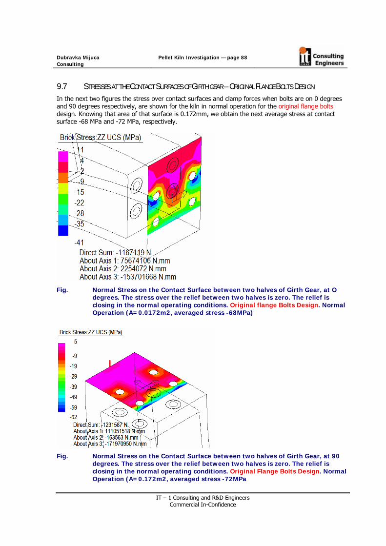
Dubravka Mijuca Consulting
Pellet Kiln Investigation — page 88
IT – 1 Consulting and R&D Engineers Commercial In-Confidence
9.7 STRESSES AT THE CONTACT SURFACES OF GIRTH GEAR – ORIGINAL FLANGE BOLTS DESIGN
In the next two figures the stress over contact surfaces and clamp forces when bolts are on 0 degrees and 90 degrees respectively, are shown for the kiln in normal operation for the original flange bolts design. Knowing that area of that surface is 0.172mm, we obtain the next average stress at contact surface -68 MPa and -72 MPa, respectively.
Fig. Normal Stress on the Contact Surface between two halves of Girth Gear, at O degrees. The stress over the relief between two halves is zero. The relief is closing in the normal operating conditions. Original flange Bolts Design. Normal Operation (A=0.0172m2, averaged stress -68MPa)
Fig. Normal Stress on the Contact Surface between two halves of Girth Gear, at 90 degrees. The stress over the relief between two halves is zero. The relief is closing in the normal operating conditions. Original Flange Bolts Design. Normal Operation (A=0.172m2, averaged stress -72MPa

Dubravka Mijuca Consulting
Pellet Kiln Investigation — page 89
IT – 1 Consulting and R&D Engineers Commercial In-Confidence
In the next two figures the stress over contact surfaces and clamp forces when bolts are on 0 degrees and 90 degrees respectively, are shown for the kiln in normal operation for the proposed flange bolts design. Knowing that area of that surface is 0.172mm, we obtain the next average stress at contact surface -67 MPa and -68 MPa, respectively.
Fig. Normal Stress on the Contact Surface between two halves of Girth Gear, at 0 degrees. The stress over the relief between two halves is zero. The relief is closing in the normal operating conditions. Proposed Flange Bolts Design. Normal Operation (A=0.172m2, avraged stress -67 MPa)
Fig. Normal Stress on the Contact Surface between two halves of Girth Gear, at 90
degrees. The stress over the relief between two halves is zero. The relief is closing in the normal operating conditions. Proposed Flange Bolts Design. Normal Operation (A=0.172m2, averaged stress -68 MPa)

Dubravka Mijuca Consulting
Pellet Kiln Investigation — page 90
IT – 1 Consulting and R&D Engineers Commercial In-Confidence
10. HOT SPOT OPERATING CONDITION
The Hotspot located in the middle of the Section 4, between Uphill Tyre and Girth Gear, where the angle of the HOT SPOT is 90 degrees, of length 500mm, spanning from 11339.91mm to 11887.79mm,is considered in the present section. The hot spot rotates with the kiln, and presently its two positions are examined at 12 o’clock, and at 9 o’clock. This hotspot scenario should simulate available thermalvision measurements data of the kiln taken on October 3, 2006 shown in the next Figure.
Fg. The thermalvision scanning of the present kiln
The four scenarios of the influence of the Hotspot on the Flange Bolts, for the Original and Proposed Flange Bolts Design, are investigated. Therefore, we will have 8 cases to look after. First case considered is when Hotspot is aligned with bolts. The second case considered is when Hotspot is at 90 from bolts. Then for each case the bolts stress for two orientations of bolts on the kiln is calculated, when Flange Bolts are at 90 deg and 270 deg (which gave max bolt stresses in normal operating condition). and Flange Bolts at 0 and 180 deg (which gave the minimum bolt stress in normal operating condition of the kiln). This aim of this analysis is to see if the stress range is going to change significantly in accordance to that in normal operating condition of the kiln.
Two considered Hotspot locations are shown in the next Figure Hotspot is denoted by the blue color on refractory. The Hotspot is simulated by increasing the value of the thermal conductivity to 0.0066 [W/mmK] at this location from initial 0.0014.
Firstly, contact elements are changed to truss and divided by two to meet nodes at the central sections of the bolts. Then steady state heat analysis is performed. After that, truss elements are deleted and contact elements are recovered (copied) taking care that original temperatures from steady state analysis are maintained on the common points with contact elements.

Dubravka Mijuca Consulting
Pellet Kiln Investigation — page 91
IT – 1 Consulting and R&D Engineers Commercial In-Confidence
Fig. Location of the Hot Spots UP on 0 degrees
Fig. Location of the Hot Spots Left (looking from the discharge end) on 90 degrees

Dubravka Mijuca Consulting
Pellet Kiln Investigation — page 92
IT – 1 Consulting and R&D Engineers Commercial In-Confidence
10.1 HOTSPOT ON 0 DEG
10.1.1. TEMPERATURES Comparing to the kiln in normal operating condition the maximal temperature of the refractory increases for 48 C (before 1301 C), while maximum temperature on the shell increases for 104 C (before 286).
Fig. Temperature field of the kiln with Hotspot in Section 4 UP.
Fig. Temperature field of the shell, Girth Gear and Tyres of the kiln with Hotspot in Section 4 UP.

Dubravka Mijuca Consulting
Pellet Kiln Investigation — page 93
IT – 1 Consulting and R&D Engineers Commercial In-Confidence
Fig. Temperature of the shell with Hotspot in Section 4 UP.
Tangent plates have a temperature rang spanning from 75 C on the outer surface in connection to girth gear to 250, which is 2 C increase in maximum temperatures.
Fig. Temperature of the tangent plates with Hotspot in Section 4 UP.

Dubravka Mijuca Consulting
Pellet Kiln Investigation — page 94
IT – 1 Consulting and R&D Engineers Commercial In-Confidence
Girth gear do not change a temperature rang, and its spans from 49 C on the outer surface in connection to girth gear to 89 C on the contact points with tangent plates.
Fig. Temperature of the Girth Gear with Hotspot in Section 4 UP.
10.1.2. DISPLACEMENTS FOR KILN WITH HOT SPOT AT 0 DEGREES (12 O’CLOCK) Elongation of the shell with hot spot at 0 degrees is from -25.8mm to 75.9mm, which is longer by 1.6 mm than in normal operation of the kiln.
Fig. Elongation of the kiln with Hot Spot at 0 degrees (12 o’clock)

Dubravka Mijuca Consulting
Pellet Kiln Investigation — page 95
IT – 1 Consulting and R&D Engineers Commercial In-Confidence
Minimal and maximal radial displacements of the shell are from -2 and 19 mm respectively. The maximal radial displacement of the shell increases bellow hot spot for about 4 mm in according to kiln in normal operation and now it is 19 mm.
Fig. Kiln with Hotspot in Section 4 UP, Radial displacements, all displacements magnified 1000 times
Minimal and maximal tangential displacements of the shell are from -4.5 to 12.8 mm. The maximal tangential of the shell increases bellow hot spot for about 0.4mm in according to kiln in normal operation (in NO was 12.4mm).
Fig. Kiln with Hotspot in Section 4 UP, Tangential displacements, all displacements
magnified 1000 times

Dubravka Mijuca Consulting
Pellet Kiln Investigation — page 96
IT – 1 Consulting and R&D Engineers Commercial In-Confidence
10.1.3. STRESS FOR KILN WITH HOT SPOT AT 0 DEGREES
The tangential stresses on the shell below hot spot at 0 degrees (0 o’clock) are both compressive and tension and are in rang from [-112, 130] MPa.
Fig. Circumferential Stress of the shell with Hotspot in Section 4 up. Magnified 1000 times.
The radial stresses on the shell below hot spot at 0 degrees (0 o’clock) are both compressive and tension and are in rang from [-22, 27] MPa.
Fig. Radial Stress of the shell with Hotspot in Section 4 up. Magnified 1000 times.

Dubravka Mijuca Consulting
Pellet Kiln Investigation — page 97
IT – 1 Consulting and R&D Engineers Commercial In-Confidence
In the next Figure, we can see that in the vicinity of Hotspot radial displacement of the shell is increased by the 5mm comparing to normal operating conditions.
Fig. Radial Displacement of the Section 4, under Normal and Hot Spot Up operating conditions, respectively. Magnified 1000 times
From the next Figure we may see that there is no substantial difference between displacements of the shell’s section 4 when using Original and Proposed Flange Bolt designs, the difference is 0.8mm.
Fig. Radial Displacement of the Section 4 with Hot Spot UP, proposed and existing Flange Bolts designs, respectively. Magnified 1000 times

Dubravka Mijuca Consulting
Pellet Kiln Investigation — page 98
IT – 1 Consulting and R&D Engineers Commercial In-Confidence
The difference of radial displacement of the Girth Gear, when using Original and Proposed Flange Bolt design, is 0.48mm (proposed bolt design induces bigger displacements on girth gear).
Fig. Radial Displacement of the Girth Gear in Hotspot scenario, for Proposed and Existing Flange Bolt design, respectively, for the shell with hot spot at 0 degrees

Dubravka Mijuca Consulting
Pellet Kiln Investigation — page 99
IT – 1 Consulting and R&D Engineers Commercial In-Confidence
10.1.4. REACTIONS AT THE SUPPORTS FOR THE SHELL WITH HOT SPOT AT 12 O’CLOCK
Reaction forces at contact with uphill left tyre is for kiln in the normal operation were 2037506N, with uphill right tyre is 2618348N, with downhill left tyre is 2482083N and with downhill right tyre is 2704425N.
Presently, for a shell with hot spot at 12 o’clock the reaction forces are: uphill left tyre 2035927, uphill right tyre is 2617219 N, with downhill left tyre is 2481862 N and with downhill right tyre is 2704203 N.
Fig. Reaction forces at the restraints for the kiln with Hot Spot on the 0 degrees (UP)

Dubravka Mijuca Consulting
Pellet Kiln Investigation — page 100
IT – 1 Consulting and R&D Engineers Commercial In-Confidence
10.2 HOTSPOT ON 90 DEG (9 O’CLOCK)
10.2.1. TEMPERATURES FOR THE KILN WITH HOT SPOT AT 90 DEGREES
Fig. Temperature field of the kiln with Hotspot in Section 4 left of Girth Gear
Fig. Temperature of the kiln with hotspot in Section 4 LEFT.
Fig. Temperature of the kiln shell with hotspot in Section 4 LEFT.

Dubravka Mijuca Consulting
Pellet Kiln Investigation — page 101
IT – 1 Consulting and R&D Engineers Commercial In-Confidence
10.2.2. DISPLACEMENTS FOR THE KILN WITH HOT SPOT AT 90 DEGREES
Minimal and maximal radial displacements of the kiln are from -8 and 18 mm respectively.
Fig. Radial displacement of the kiln with hotspot in Section 4 LEFT (90 degrees).
Minimal and maximal radial displacements of the shell are from -3 and 17 mm respectively.
Fig. Radial displacement of the shell with Hotspot in Section 4 LEFT of Girth Gear, all displacements magnified 1000 times

Dubravka Mijuca Consulting
Pellet Kiln Investigation — page 102
IT – 1 Consulting and R&D Engineers Commercial In-Confidence
10.2.3. STRESSES FOR THE KILN WITH HOT SPOT AT 90 DEGREES
The tangential stresses on the shell below hot spot at 90 degrees (9 o’clock) are both compressive and tension and are in rang from [-114, 140] MPa.
Fig. Tangential Stress of the kiln shell with Hotspot located in Section 4 LEFT, all displacements magnified 1000 times
Fig. Tangential Stress of the kiln shell with, except for the Section 4 where hotspot is located LEFT, all displacements magnified 1000 times

Dubravka Mijuca Consulting
Pellet Kiln Investigation — page 103
IT – 1 Consulting and R&D Engineers Commercial In-Confidence
The radial stresses on the shell below hot spot at 90 degrees (9 o’clock) are both compressive and tension and are in rang from [-24, 30] MPa.
Fig. Radial Stress of the kiln shell with, where hotspot is located LEFT, all displacements magnified 1000 times

Dubravka Mijuca Consulting
Pellet Kiln Investigation — page 104
IT – 1 Consulting and R&D Engineers Commercial In-Confidence
10.2.4. REACTIONS AT THE SUPPORTS FOR SHEL WITH HOT SPOT AT 9 O’CLOCK
Reaction forces at contact with uphill left tyre is for kiln in the normal operation were 2037506N, with uphill right tyre is 2618348N, with downhill left tyre is 2482083N and with downhill right tyre is 2704425N.
Presently, for a shell with hot spot at 12 o’clock the reaction forces are: uphill left tyre 2035982, uphill right tyre is 2617273 N, with downhill left tyre is 2481882 N and with downhill right tyre is 2704224 N.
Fig. Reaction forces at the restraints for the kiln with Hot Spot on the 90 degrees (LEFT)

Dubravka Mijuca Consulting
Pellet Kiln Investigation — page 105
IT – 1 Consulting and R&D Engineers Commercial In-Confidence
10.3 TABLES AND DIAGRAMS
Fig. Hot spot at 90 degrees (left) – Tangential stress along kiln at different angles, hotspot spanning fro 11339.91 mm to 11888.79mm.
Fig. Hot spot at 90 degrees (left) – Radial displacement stress along kiln at different angles, hotspot spanning fro 11339.91 mm to 11888.79mm.

Dubravka Mijuca Consulting
Pellet Kiln Investigation — page 106
IT – 1 Consulting and R&D Engineers Commercial In-Confidence
Table Radial displacement and Tangential stresses of the Kiln with Hotspot of 400C at 90 deg LEFT
Kiln with Hot Spot
90 deg LEFT
Radial displacement [mm] Tangential Stress [MPa] Longitudinal Coordinate
[mm] 90 deg 180 deg 270 deg 0 deg 90 deg 180 deg 270 deg 0 deg
0 6.02 12.5 9.67 0.14 15.09 3.9 12.13 11.262498.72 8.08 12.2 10.85 -0.48 7.4 -10.86 8.72 2.874997.45 9.99 11.76 11.96 -1.12 11.79 1.12 12.14 13.426364.29 11 11.46 12.5 -1.48 0.8 -2.01 -0.8 -1.537731.12 11.86 11.03 12.82 -2.15 -12.82 -10.69 -13.23 -22.82
8001 11.96 10.88 12.79 -2.43 -32.55 -25.34 -32.1 -56.78213.72 12.02 10.75 12.75 -2.67 5.14 12.69 6.44 -32.428712.2 12.26 10.55 12.75 -2.98 12.1 27.19 17.31 -26.84
9210.67 12.66 10.51 12.91 -2.9 -6.34 10.37 2.32 -27.959423.4 12.91 10.54 13.02 -2.77 -47.34 -28.18 -37.49 -54.2
9693.27 13.33 10.58 13.14 -2.61 -13.79 -8.56 -14.53 -21.1410791.03 15.38 10.56 13.25 -2.44 114.97 -2.24 1.09 2.211339.91 16.25 10.48 13.16 -2.48 -113.49 0.43 6.75 8.8711888.79 16.14 10.35 12.91 -2.6 -106.02 -0.16 5.21 4.0712543.54 14.86 10.15 12.5 -2.79 102.32 -10.14 -6.68 -10.0813198.29 13.46 9.93 12.03 -3.02 13.39 2.18 6.09 5.6813528.29 12.91 9.85 11.82 -3.12 -14.73 -1.32 2.25 2.4913603.29 12.84 9.85 11.79 -3.13 -16.69 -3.34 0.21 0.4213678.29 12.82 9.87 11.78 -3.11 -14.87 -2.21 1.4 1.5114008.29 12.9 10.02 11.83 -2.97 0.52 3.72 9.36 7.21
14084.3 12.92 10.06 11.85 -2.94 8.45 2.93 18.03 9.8915043.94 13.11 10.44 12.01 -2.49 -5.55 -37.9 -5.6 -22.4916003.59 13.06 10.54 11.97 -2.29 21.44 -14.11 18.22 -6.0517922.87 12.85 10.43 11.76 -2.23 11.85 -6.49 11.65 120299.36 12.8 10.17 11.7 -2.24 2.43 -9.87 2.63 -4.0722675.85 12.84 9.84 11.74 -2.3 10.38 1.43 10.5 7.8424042.69 12.96 9.73 11.87 -2.28 -1.54 -4.85 -1.61 -0.2325409.52 13.02 9.61 11.91 -2.43 -2.13 1.8 -3.16 -11.09
25679.4 12.99 9.57 11.86 -2.56 -35.49 -26.8 -35.59 -52.0225892.13 12.93 9.53 11.8 -2.69 -2.43 5.29 -2.19 -31.48
26390.6 12.86 9.47 11.69 -2.82 10.42 21.37 11.17 -28.7226889.07 12.87 9.5 11.67 -2.6 -3.24 4.08 -2.69 -33.36
27101.8 12.89 9.53 11.68 -2.42 -37.09 -28.96 -36.6 -53.6127371.67 12.88 9.55 11.64 -2.25 -4.36 -1.58 -4.64 -12.228738.51 12.56 9.5 11.15 -1.86 4.9 0.39 3.48 2.2630105.35 12.21 9.49 10.57 -1.59 6.11 -3.07 6.51 5.9232515.17 11.59 9.58 9.51 -1 3.61 -8.16 2.96 -1.67
34925 10.92 9.66 8.38 -0.36 11.76 -1.17 9.29 3.1535521.9 10.78 9.71 8.14 -0.17 7.08 -14.05 4.07 -2.9436118.8 10.69 9.79 7.92 0.05 11.25 -9.53 7.32 -0.31

Dubravka Mijuca Consulting
Pellet Kiln Investigation — page 107
IT – 1 Consulting and R&D Engineers Commercial In-Confidence
10.4 STRESS CALCULATION OF FLANGE BOLTS UNDER HOTSPOTS
This aim of this analysis is to see if the stress range is going to change significantly in accordance to that in normal operating condition of the kiln.
The four scenarios of the influence of the Hotspot on the Flange Bolts, for the Original and Proposed Flange Bolts Design, are investigated. Therefore, we will have 8 cases to look after. First case considered is when Hotspot is aligned with bolts. The second case considered is when Hotspot is at 90 from bolts. Then for each case the bolts stress for two orientations of bolts on the kiln is calculated, when Flange Bolts are at 90 deg and 270 deg (which gave max bolt stresses in normal operating condition). and Flange Bolts at 0 and 180 deg (which gave the minimum bolt stress in normal operating condition of the kiln).
Temperature of the Flange Bolt in present hot spot scenario is about 77 C, that is 2 C degrees more than in normal operating condition (see Figure *).
Fig. Temperature of the Bolt on 270 degrees (3 o’clock) when hot spot is up in Section 4]

Dubravka Mijuca Consulting
Pellet Kiln Investigation — page 108
IT – 1 Consulting and R&D Engineers Commercial In-Confidence
10.5 STRESSES AT CENTRES OF THE FLANGE BOLTS
The Original Flange Bolt design has initial preload of 483MPa, while Proposed Flange Bolt design has initial preloaded of 575MPa. In the kiln under Hot spot operating conditions preload stress in the bolts changes to the values given in the next tables:
Table *. HOT SPOT ALIGNED WITH BOLTS WHICH ARE IN POSITIONS O AND 3 Longitudinal Stress [MPa]
ORIGINAL DESIGN Stress at Centre of the Flange Bolts [MPa]
HOT SPOT UP HOT SPOT LEFT Difference
Bolts Position
0 degrees
90degrees
Uphill Bolt 486 690 204 Downhill Bolt 485 683 198
Bolts Position
180 degrees
270 degrees
Uphill Bolt 486 664 178 Downhill Bolt 486 668 180
Longitudinal Stress [MPa]
PROPOSED DESIGN Stress at Centre of the Flange Bolts [MPa]
HOT SPOT UP HOT SPOT LEFT
Bolts Position
0 degrees
90degrees
Uphill Bolt 598 784 186 Downhill Bolt 597 790 193
Bolts Position
180 degrees
270 degrees
Uphill Bolt 599 765 166 Downhill Bolt 598 769 171

Dubravka Mijuca Consulting
Pellet Kiln Investigation — page 109
IT – 1 Consulting and R&D Engineers Commercial In-Confidence
Table *. HOT SPOT AT 90 DEGREES FROM BOLTS WHICH ARE IN POSITIONS O AND 3 Longitudinal Stress [MPa]
ORIGINAL DESIGN Stress at Centre of the Flange Bolts [MPa]
HOT SPOT UP HOT SPOT LEFT Difference
Bolts Position
90degrees
180 degrees
Uphill Bolt 645 482 163 Downhill Bolt 640 480 160
Bolts Position
270 degrees
0 degrees
Uphill Bolt 626 479 147 Downhill Bolt 625 481 144
Longitudinal Stress [MPa]
PROPOSED DESIGN Stress at Centre of the Flange Bolts [MPa]
HOT SPOT UP HOT SPOT LEFT
Bolts Position
90degrees
180 degrees
Uphill Bolt 746 595 151 Downhill Bolt 742 594 148
Bolts Position
270 degrees
0 degrees
Uphill Bolt 729 594 135 Downhill Bolt 727 593 134
The stress range when hot spot is aligned with bolts is bigger than when hot spot is at 90 degrees to the bolts in the case of the both bolts design, original and proposed. For both these hot spot scenarios stress range in original bolt design is bigger than for proposed. Namely, original bolt design suffers stress rang in the amount of 204 MPa, while proposed it is 193 MPa.

Dubravka Mijuca Consulting
Pellet Kiln Investigation — page 110
IT – 1 Consulting and R&D Engineers Commercial In-Confidence
10.6 STRESSES AT THE CONTACT SURFACES OF GIRTH GEAR – HOTSPOT AT 0 DEGREES – ORIGINAL FLANGE
BOLTS
Table Normal Stress on the Contact Surface between two halves of Girth Gear, at O
degrees. Original Flange Bolt Design. The stress over the relief between two halves is zero. Hotspot at 0 degrees
Table Normal Stress on the Contact Surface between two halves of Girth Gear, at 9O degrees. Original Flange Bolt Design. The stress over the relief between two halves is zero. Hotspot at 90 degrees.

Dubravka Mijuca Consulting
Pellet Kiln Investigation — page 111
IT – 1 Consulting and R&D Engineers Commercial In-Confidence
10.7 STRESSES AT THE CONTACT SURFACES OF GIRTH GEAR – HOTSPOT AT 0 DEGREES – PROPOSED FLANGE
BOLTS
Table Normal Stress on the Contact Surface between two halves of Girth Gear, at O degrees. Proposed Flange Bolt Design. The stress over the relief between two halves is zero. Hotspot at 0 degrees.
Table Normal Stress on the Contact Surface between two halves of Girth Gear, at 9O degrees. Proposed Flange Bolt Design. The stress over the relief between two halves is zero. Hotspot at 90 degrees
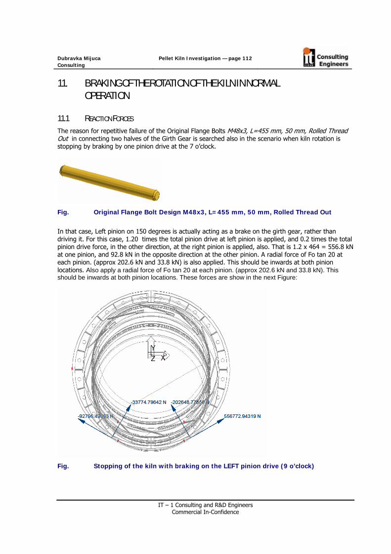
Dubravka Mijuca Consulting
Pellet Kiln Investigation — page 112
IT – 1 Consulting and R&D Engineers Commercial In-Confidence
11. BRAKING OF THE ROTATION OF THE KILN IN NORMAL
OPERATION
11.1 REACTION FORCES
The reason for repetitive failure of the Original Flange Bolts M48x3, L=455 mm, 50 mm, Rolled Thread Out in connecting two halves of the Girth Gear is searched also in the scenario when kiln rotation is stopping by braking by one pinion drive at the 7 o’clock.
Fig. Original Flange Bolt Design M48x3, L=455 mm, 50 mm, Rolled Thread Out
In that case, Left pinion on 150 degrees is actually acting as a brake on the girth gear, rather than driving it. For this case, 1.20 times the total pinion drive at left pinion is applied, and 0.2 times the total pinion drive force, in the other direction, at the right pinion is applied, also. That is 1.2 x 464 = 556.8 kN at one pinion, and 92.8 kN in the opposite direction at the other pinion. A radial force of Fo tan 20 at each pinion. (approx 202.6 kN and 33.8 kN) is also applied. This should be inwards at both pinion locations. Also apply a radial force of Fo tan 20 at each pinion. (approx 202.6 kN and 33.8 kN). This should be inwards at both pinion locations. These forces are show in the next Figure:
Fig. Stopping of the kiln with braking on the LEFT pinion drive (9 o’clock)

Dubravka Mijuca Consulting
Pellet Kiln Investigation — page 113
IT – 1 Consulting and R&D Engineers Commercial In-Confidence
Reaction forces at contact with uphill left tyre is for kiln in the normal operation were 2037506N, with uphill right tyre is 2618348N, with downhill left tyre is 2482083N and with downhill right tyre is 2704425N.
Presently, for a kiln which brakes at left pinion, the reaction forces are: uphill left tyre 1938041, uphill right tyre is 2397180 N, with downhill left tyre is 2444210 N and with downhill right tyre is 2619829 N.
The reaction forces in that case are shown in the next Figure.
Fig. Reaction forces of the kiln in braking of rotation

Dubravka Mijuca Consulting
Pellet Kiln Investigation — page 114
IT – 1 Consulting and R&D Engineers Commercial In-Confidence
11.2 STRESSES AT THE CONTACT SURFACES OF GIRTH GEAR – BRAKING KILN – ORIGINAL BOLTS
In the next two figures the stress over contact surfaces and clamp forces when bolts are on 0 degrees and 90 degrees respectively, are shown for the kiln which brakes. Knowing that area of that surface is 0.172mm, we obtain the next average stress at contact surface -82 MPa and -72 MPa, respectively.
Fig. Normal Stress on the Contact Surface between two halves of Girth Gear, at O
degrees. Original Flange Bolt Design. The stress over the relief between two halves is zero. Braking Kiln. (A=0.0172m2, , average stress -82 MPa)
Fig. Normal Stress on the Contact Surface between two halves of Girth Gear, at 180
degrees. Original Flange Bolt Design. The stress over the relief between two halves is zero. Braking Kiln. (A=0.0172m2, , average stress -72 MPa))

Dubravka Mijuca Consulting
Pellet Kiln Investigation — page 115
IT – 1 Consulting and R&D Engineers Commercial In-Confidence
11.3 STRESSES OF THE FLANGE BOLTS
KILN IN BREAKING OF THE ROTATION Longitudinal Stress at Centre of the Flange Bolts [MPa]
/looking from the discharge end/
ORIGINAL DESIGN
Bolts Position
0 degrees
30 degrees
60 degrees
90degrees
120 degrees
150 degrees
Uphill Bolt 483 498 593 667 627 510
Downhill Bolt 482 497 593 667 627 510
Bolts Position
180 degrees
210 degrees
240 degrees
270 degrees
300 degrees
330 degrees
Uphill Bolt 487 505 581 661 619 515
Downhill Bolt 486 504 579 661 619 515
The results of the operating with one pinion braking also showed that the forces from the pinions have very little effect on the bolt stress range

Dubravka Mijuca Consulting
Pellet Kiln Investigation — page 116
IT – 1 Consulting and R&D Engineers Commercial In-Confidence
12. ELASTOSTATICS ANALYSIS OF THE COLD KILN
12.1 DISPLACEMENTS
12.1.1. ELONGATION
Kiln does not extend its length in cold state.
Fig. Elongation of the cold kiln
12.1.2. RADIAL DISPLACEMENTS
Minimal and maximal radial displacements of the shell are -6.2 and 4.51mm respectively.
Fig. Radial displacement of the cold kiln

Dubravka Mijuca Consulting
Pellet Kiln Investigation — page 117
IT – 1 Consulting and R&D Engineers Commercial In-Confidence
Fig. Radial displacements of the cold kiln
Minimal and maximal radial displacements of the shell are from -6.2 and 4.5 mm respectively.
Fig. Radial displacement of the shell in cold state

Dubravka Mijuca Consulting
Pellet Kiln Investigation — page 118
IT – 1 Consulting and R&D Engineers Commercial In-Confidence
12.1.3. EXAGGERATED DISPLACEMENTS OF THE SHELL SECTION 4
Fig. 500 times Exaggerated displacements of the Shell Section 4
Fig. Displacement of the whole shell exaggerated 500 times.
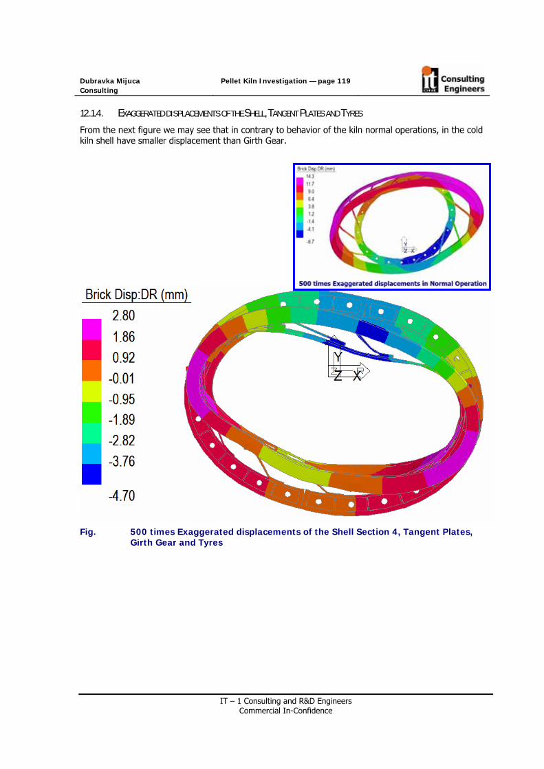
Dubravka Mijuca Consulting
Pellet Kiln Investigation — page 119
IT – 1 Consulting and R&D Engineers Commercial In-Confidence
12.1.4. EXAGGERATED DISPLACEMENTS OF THE SHELL, TANGENT PLATES AND TYRES
From the next figure we may see that in contrary to behavior of the kiln normal operations, in the cold kiln shell have smaller displacement than Girth Gear.
Fig. 500 times Exaggerated displacements of the Shell Section 4, Tangent Plates, Girth Gear and Tyres

Dubravka Mijuca Consulting
Pellet Kiln Investigation — page 120
IT – 1 Consulting and R&D Engineers Commercial In-Confidence
12.2 STRESS
12.2.1. RADIAL STRESS OF THE SHELL
Fig. Radial stresses of the shell in the cold kiln
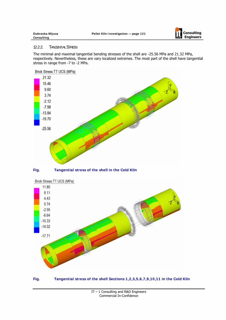
Dubravka Mijuca Consulting
Pellet Kiln Investigation — page 121
IT – 1 Consulting and R&D Engineers Commercial In-Confidence
12.2.2. TANGENTIAL STRESS
The minimal and maximal tangential bending stresses of the shell are -25.56 MPa and 21.32 MPa, respectively. Nevertheless, these are vary localized extremes. The most part of the shell have tangential stress in range from -7 to -2 MPa.
Fig. Tangential stress of the shell in the Cold Kiln
Fig. Tangential stress of the shell Sections 1,2,3,5,6,7,9,10,11 in the Cold Kiln

Dubravka Mijuca Consulting
Pellet Kiln Investigation — page 122
IT – 1 Consulting and R&D Engineers Commercial In-Confidence
In girth gear average values of tangential stress are about 8.29 MPa, except at the contact with washers/spacers around Flange Bolts where this value is much higher and compressive, and around Positioning Bolts.
Fig. Tangential stress of the Section 4, Tangent Plates and Girth Gear in the Cold Kin

Dubravka Mijuca Consulting
Pellet Kiln Investigation — page 123
IT – 1 Consulting and R&D Engineers Commercial In-Confidence
Tangential stress of the tangent plates in the cold kiln are in range from -32.1 MPa to 35.2 MPa The average stresses are in the middle of the tangent plates in the amount of the 1.6MPa.
Fig. Tangential stresses of the tangent plate sin the cold kiln

Dubravka Mijuca Consulting
Pellet Kiln Investigation — page 124
IT – 1 Consulting and R&D Engineers Commercial In-Confidence
12.3 STRESSES AT THE CONTACT SURFACES OF GIRTH GEAR – COLD KILN – ORIGINAL BOLTS
In the next two figures the stress over contact surfaces and clamp forces when bolts are on 0 degrees and 90 degrees respectively, are shown for the cold kiln. Knowing that area of that surface is 0.172mm, we obtain the next average stress at contact surface -118 MPa and -106 MPa, respectively.
Fig. Normal Stress on the Contact Surface between two halves of Girth Gear, at O degrees. Original Flange Bolt Design. The stress over the relief between two halves is zero. Cold Kiln. (A=0.0172mm2, average stress -118 MPa)
Fig. Normal Stress on the Contact Surface between two halves of Girth Gear, at 180 degrees. Original Flange Bolt Design. The stress over the relief between two halves is zero. Cold Kiln. (A=0.0172m2, average stress -106 MPa)
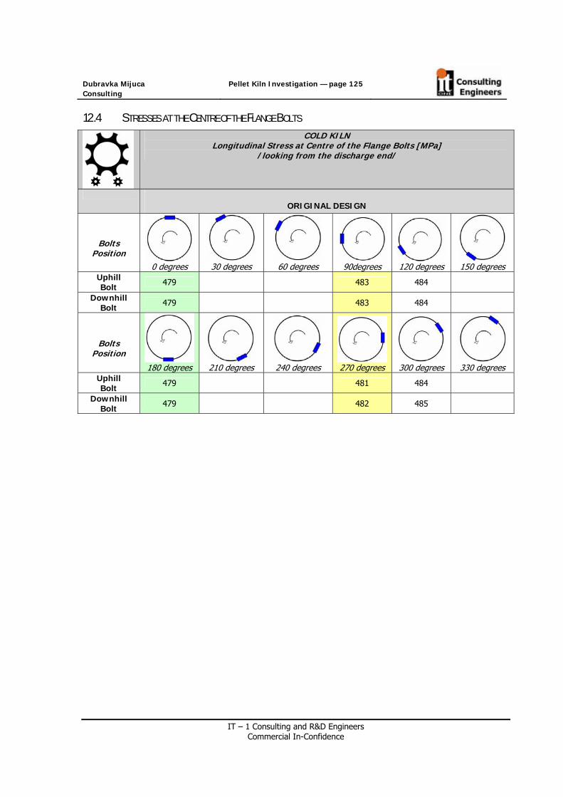
Dubravka Mijuca Consulting
Pellet Kiln Investigation — page 125
IT – 1 Consulting and R&D Engineers Commercial In-Confidence
12.4 STRESSES AT THE CENTRE OF THE FLANGE BOLTS
COLD KILN Longitudinal Stress at Centre of the Flange Bolts [MPa]
/looking from the discharge end/
ORIGINAL DESIGN
Bolts Position
0 degrees
30 degrees
60 degrees
90degrees
120 degrees
150 degrees
Uphill Bolt 479 483 484
Downhill Bolt 479 483 484
Bolts Position
180 degrees
210 degrees
240 degrees
270 degrees
300 degrees
330 degrees
Uphill Bolt 479 481 484
Downhill Bolt 479 482 485

Dubravka Mijuca Consulting
Pellet Kiln Investigation — page 126
IT – 1 Consulting and R&D Engineers Commercial In-Confidence
12.5 REACTIONS ATE THE SUPPORT OF THE COLD KILN
Reaction forces at contact with uphill left tyre is for kiln in the normal operation were 2037506N, with uphill right tyre is 2618348N, with downhill left tyre is 2482083N and with downhill right tyre is 2704425N.
Presently, for a cold kiln the reaction forces are: uphill left tyre 2037056, uphill right tyre is 2618348 N, with downhill left tyre is 2482083 N and with downhill right tyre is 2704425 N.
Fig. Reaction forces of the cold

Dubravka Mijuca Consulting
Pellet Kiln Investigation — page 127
IT – 1 Consulting and R&D Engineers Commercial In-Confidence
13. CONTACT ANALYIS
438 Beam finite elements named Point Contact Elements are used to simulate the contact analysis between two halves of the Girth Gear.
The properties for that finite element are taken to be: Initial Stiffness 100 [N/mm], Friction C1 is 1, and Friction C2 is 1.
The total length of all beams is 4.4 mm.

Dubravka Mijuca Consulting
Pellet Kiln Investigation — page 128
IT – 1 Consulting and R&D Engineers Commercial In-Confidence
14. REMARK
Although Pellet is not solid material, it must be considered as the solid in Finite Element analysis. The small value is chosen for its Young’s Modulus in amount of 0.5 MPa.
Refractory is also pice-vice solid material made of solid bricks. Nevertheless, above remarks holds for this case also. It is taken that Young’s Modulus for Refractory is 100 MPa. It is found that further decreasing of the Young Modulus for Refractory to 10 MPa does not decrease the stress range in bolts. Namely, the stress decrease for about 1MPa per bolt.
15. REFERENCES
[Jaccard 2004] Case Study on Fiscal Policy and Energy Efficiency Economic Study, M.K. Jaccard & Associates (2004)
[Phillips 2007] Phillips Kiln Service Ltd.

Dubravka Mijuca Consulting
Pellet Kiln Investigation — page 129
IT – 1 Consulting and R&D Engineers Commercial In-Confidence