integral formulation for the calculation of the field and the forces in a system of conducting...
TRANSCRIPT

Integral formulation for the calculation of the fieldand the forces in a system of conducting cylindricalshells: a general approach
M.N. ZervasProf. E.E. Kriezis
Indexing terms: Electromagnetic theory, Conductors and conductivity, Mathematical techniques
Abstract: The problem of calculating current den-sities in a system of cylindrical shells is examined.The geometrical configuration of the system con-sists of a circular cylindrical shell enclosing anumber of hollow circular cylindrical conductorsplaced in arbitrary positions. The calculation ofthe current densities is based on the solution of asystem of integral equations. For the numericalsolution of these equations the method ofmoments is applied. The forces acting on the con-ductors are calculated as well.
1 Introduction
The problem of current distribution in circular cylin-drical devices, when the excitation consists of one ormore current filaments, has been investigated assumingthat the filaments have cross sections of zero dimensions.The problem was examined by using either an integralformulation [1] or a differential formulation [2-5].
The existence of devices including conductors withcross-sections of nonzero dimensions created the need forexamining the problem by considering a general excita-tion element [6].
In a recent paper [7] the electromagnetic forces arecalculated in 3-phase cables. The problem is tackled byusing a differential formulation and the electromagneticforces are calculated in the case of symmetrically equi-. spaced hollow conductors under the condition of a3-phase short circuit. In this work the problem is treatedby considering more than one conductor inside a circularcylindrical shell. This configuration represents thegeometry in substations insulated by SF6 or in high-voltage gas-insulated transmission cables.
The method of this work permits the calculation of thedistributed current density across both the excitationconductors and their cylindrical enclosure. The loss ofthe system of cylindrical shells as well as the forces actingon the conductors can then be calculated. The knowndistribution of the current density gives the possibility ofcalculating the field magnitudes in every region of thegeometrical configuration.
The calculation of the forces is important, especially inthe case of either a short circuit or if the current densitiesare strongly assymetrical. From the forces the bending
Paper 5506B (PI, S8), received 8th April 1987The authors are with the Aristotle University of Thessaloniki, Facultyof Engineering, School of Electrical Engineering, Thessaloniki, Greece
IEE PROCEEDINGS, Vol. 134, Pt. B, No. 5, SEPTEMBER 1987
stress can be determined. According to the method it ispossible for the forces to be calculated when one, two orthree conductors are short circuited.
The problem has been considered in its most generalform, where the excitation conductors have a hollowcylindrical geometry and their positions inside the enclo-sure shell have been taken arbitrarily.
The application of the method of moments for thenumerical treatment of the problem has the advantage ofusing more complicated geometrical shapes of the con-ductors and considering conductors located in arbitraryplaces.
2 Development of the integral equations
Three cylindrical conductors are placed inside a conduct-ing cylindrical shell (Fig. 1). The magnetic vector poten-tials (MVP) A of the conductors are Au A2, A3, A4 forthe shell and three conductors, respectively. Consideringthe infinite length of the conductors it is obvious that allthe vectors of the MVP and the current densities J onlyhave a z-component.
Fig. 1 Geometrical configuration
The MVP Au at the point Mj of the shell due to thecurrent density /, (i = 1, 2, 3, 4) of the ith conductor iswritten
/i0 fAu = — — I In duJ^Pii
2n Jsuwhere b'u are constants.
(1)
269

The total MVP at the point Mt according to thesuperposition principle will be
The MVP AOl at the point 0x will be
^n « = i JsJiiPu) ds(Pli) + b'
(2)
(3)
where b' is a constant.Using the integral form of Faraday's law $ E • dl =
—jco § A • dl on the loop 01M1M'10'101, the followingrelation can be written:
Mri) ~ AoJ (4)
(5)
where a = yco/io cr/27r.The vector EOlzo is the electric field intensity at the
point Oj. Considering the relation JSll J^r^) dS^^) = 7l5
eqn. 5 is written as
Inserting eqns. 2 and 3 into eqn. 4 we have
JM = oE0l + a £ f ln ̂ JM.) <tfi=l JSi, Pli
(6)
where
P n
andP u
l n ^'Sli Pli
(7)
™\i
'ii °n Pu 2(8)
From eqns. 5 and 6 the expression for the current densityJi{r^) of the cross-section of the shell is
_Jj_ y t [ du
^11 i=l Jsi, L Pli
(9)
Considering now the co-ordinate system 0, x, y{ (i = 2, 3,4) related to the cylinders 2, 3 and 4 the current densityinside these cylinders can be expressed as follows:
i(ri) = ^ + «i f [in ^ - G ^ p y•Jii j = l JSO L Pij
j y y (10)
where r; (i = 1, 2, 3, 4) the vector terminating at the point(r,-0,-) G 5,,, Pij (i, j = 1, 2, 3, 4) the vector terminating atthe point (py, 0y) e Sy, Go- = 0 for i = 2, 3, 4;j = 1, 2, 3,4; i ^ 7 and
= -̂ f l n ^
= — Ucf In -± - —l- + -tp\ i = 2, 3, 4S« L Pa 2 2 J
(11)
The vectors rt (i = 1, 2, 3, 4) are described inside its ownco-ordinate system 0,- xt y(. The vectors ptJ are the vectorsterminating at the point of the conductor; (j = 1, 2, 3, 4)inside the co-ordinate system 0,*,)', of the conductor i.The distance dtj is calculated in terms of the systemO.x.j;,. Finally, the cross-section So of the conductor) isexpressed in the system O.-x.-j;,-.
The next step is a common system of co-ordinates tobe established. This is the system 00 x0 y0 (Fig. 2).
( r 2 ( e 2 )
xo
Fig. 2 Co-ordinate system
Considering the relations, which relate the co-ordinatesystems with the common system, the following expres-sions are written
Pij = I P o u - c o i I U j = 1 , 2 , 3 , 4
Kj ~ COi) ' XOcos 0y =
I Poij ~ COi
ri = I rOi - cOi | i = l , 2 , 3 , 4
VOi ~ COi) ' X0
U = 1,2, 3,4
cos Ui = i = 1, 2, 3, 4
(12)
(13)
(14)
(15)
(16)
n - coi I
rfy = ko,--Poyl i,7 = l, 2, 3, 4
The current densities J, of the shell and the conductorsare rewritten in terms of the common system 00 x0 y0
I 4 fJiToii = -^~ + X Qoi/Toi', Poij)Jj(Poij)
i = 1, 2, 3, 4 (17)
where the kernels QOij of the integral equations are
I rOi - pou 1 ncf
I POU ~ COi I ^Oii^o.-; Po«) =a<ln
I Pou - cot I 2SOl- 2SOl-
i= 1,2, 3 , 4 (18)
_ k o i - P o i . l
- S i in*̂oi IPoi; ~ c
270
Olj ~ ^Ol I
Tib i bi 1_l In -|—
j = 2, 3,4 (19)
IEE PROCEEDINGS, Vol. 134, Pt. B, No. 5, SEPTEMBER 1987

where
/ = 2, 3, 4 j= 1, 2, 3, 4 (20)
The current densities J, will be determined from thesystem of the integral equations of eqns. 17.
3 Application of the method of moments
For the numerical treatment of the system of eqns. 17 themethod of moments is applied. Eqn. 7 is written as
4
= 3/ i = l , 2 , 3 , 4 (21)
where
= J,{r Oi) - Qo.-X'o.-; Pou)JSo
X JiiPou) dS(pOii) i= 1, 2, 3, 4
) y) dS(pOij)Soj
i = 1 , 2 , 3 , 4 j= 1,2, 3 ,4
h = -t- i = 1 , 2 , 3, 4
(22)
(23)
(24)
The cross-sections of the shell and the conductors aredivided to JV, (i = 1, 2, 3, 4) subsections by drawingcircles and straight lines passing through each centre(Fig. 3).
Fig. 3 Subregions in the method of moments
The approximate value J, (i = 1, 2, 3, 4) of the currentdensity is expressed by the relation
Ji= Za«nP.« i = 1, 2, 3, 4 (25)n = l
where a,n unknown coefficients pin is equal to 1 for thenth subsection and zero elsewhere.
Using eqns. 21 and 25 and as weight functions wn theDirac functions vvn = S(r — rn) the following relation iswritten
4 NjZ Z ajn<wim, L0(p,n)> = <wim, gt
7 = 1 n = l
where m = 1, 2 , . . . , N,; / = 1,2, 3, 4.Eqn. 26 is written in a matrix form
(26)
Z 2 '« -« / .= ft. (27)j "= l n = l
/££ PROCEEDINGS, Vol. 134, Pt. B, No. 5, SEPTEMBER 1987
Lij(Pjn)>= vv,mL0.(pJn)Js
— »*Oim)^i/Pjn) dS
and
hm = <wim, g{} = d(rOi - rOim)gi dSJs
(28)
(29)
where i = 1, 2, 3, 4, and m = 1, 2 , . . . , N{.From eqn. 27 the unknown elements ajn are deter-
mined by the matrix relation
a = r ^ (30)
where the matrices /, a and g have dimensions Zf= I Nix Z*=i Ni> Z*=i N> x ! a n d Zf=i Ni x !» respectively.
When the matrix a has been determined, the approximatevalues J of the current density are expressed as follows:
J = pr'g (31)
where
J =
P =
Pi 0 0 00 p2 0 00 0 p3 00 0 0 p.
The approximate current density J{ is
Ji=piai i = l , 2 , 3 , 4
where
a.- =a,-2
» = 1, 2, 3, 4
(32)
(33)
(34)
(35)
(36)
From the above procedure the approximate values J{ ofthe current densities on the cross sections of shell and theconductors are calculated.
4 Calculation of the forces
The calculation of the forces acting on the conductor isbased on the relation which gives the force between twocurrent filaments. Considering a current filament on theconductor i with current I£rOi), where rQi is its positionvector, and a current filament on the conductor j withcurrent Ij{pOij), where pOij is its position vector (Fig. 4),the force is expressed as follows:
VoOiJ (37)
where d{j = \ rOi - pOij\i = 2, 3, 4 , ; = 1, 2, 3, 4 and iand dOij unit vector along the segment dtj.
271

Considering the components of the infinitesimal forcedfi and integrating separately we end up with the expres-sions for the two components F, x, F, y of the total force
5 Numerical examples
A s a first example, in Fig. 5, we consider a system of threesolid conductors inside an enclosure shell. The dimen-sions are given in mm and the material is aluminum. Thecurrents are Ix = 0 A, I2 = 100 A, /3 = 100 exp DW3)]A and 74 = 100 exp (j(47r/3)] A. In Fig. 6 the currentdensities for the enclosure shell and the conductors areplotted. Fig. 7 shows the forces acting on the conductors.
The second example examines the case of hollow con-ductors. In Fig. 8 the geometry of the system is presented
Fig. 4 Geometry of the forces
7i acting on the conductor i, namely
* A.TT I
^"- JSi
f £ f J,(P0ii) COS Tjj
xj.ZJ -L"^r ^
Fig. 5 System w/tli so/id conductors
dS(rOi) (38) 8.5
f 4 f •/{/>,. ) s in T-- )i ^ ^ ° ' j y u ^S(p0 0 .) V dS(#-Ol) (39)U=i Js7 «y 3 |
where
,40)
8.0
7.5
7.0
2.5'
2.0\rOi- Poij\
The integrals of eqns. 38 and 39 can be approximated by 1 5the following series: 1 0
Ni
* m = 1
4 Nj
j=\ m=l
j = 1 n = 1
0.5
r=19mm
7'
r=118mm
7T/2
"•ijmn
(41)
TV 3TT/2 27T
0
ASim (42)
Fig. 6 Current densities on the enclosure-shell (J,) and t/ie conductors
/ , = 0 A, /2 = 100 A, / 3 = 100 exp [/(2JI/3)] A, / 4 = 100exp D(4jt/3)] A
F2|=O.O21 N/m
62=51"
where rOim is the vector terminating to the centre of themth subsections of area Sim of the conductor i, pOijrl thevector terminating to the centre of the nth area ASjn ofthe conductor j ± i and dijmn = | rOim - pOijn |. The valuesof the current densities J, are taken from the precedinganalysis. Considering harmonic time variation, the forceF(t) can be expressed as
F(t) = Re Q + Re lFi.eitar]y0 (43)
|F3|=O.O18N/n^|FA|=O.OO2 N/m
where the components F, x and FUy are given by eqns. 41and 42. Fig. 7 Forces on the solid conductors
272 IEE PROCEEDINGS, Vol. 134, Pt. B, No. 5, SEPTEMBER 1987
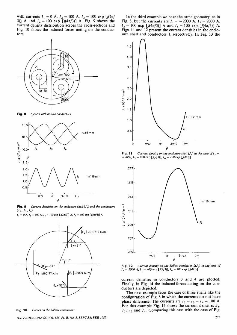
with currents It = 0 A, I2 = 100 A, 73 = 100 exp [j(2n/3)] A and 74 = 100 exp Q/(4TC/3)] A. Fig. 9 shows thecurrent density distribution across the cross-sections andFig. 10 shows the induced forces acting on the conduc-tors.
Fig. 8 System with hollow conductors
11.0
10.5/
10.0
2.5
2.0
1.5
1.0
0.5
r = 19 mm
r = 118mm
TT/2 n 3TT/2 2TT
<f>
Fig. 9 Current densities on the enclosure-shell (J,) and the conductors
/ , = 0 A, l2 = 100 A, 73 = 100 exp D(2*/3)] A, / 4 = 100 exp U'CW3)] A
|F2 |=0.0216 N/m
Fig. 10 Forces on the hollow conductors
IEE PROCEEDINGS, Vol. 134, Pt. B, No. 5, SEPTEMBER 1987
In the third example we have the same geometry, as inFig. 8, but the currents are 7X = -2000 A, 72 = 2000 A,73 = 100 exp Q"(4rc/3)] A and 74 = 100 exp Q/W3)] A.Figs. 11 and 12 present the current densities in the enclo-sure shell and conductors 1, respectively. In Fig. 13 the
U. 5
4.0
3.5
3.0
2.5CM
EE< 2.0
nOX
-»" 1.5
1.0
0.5
r=102 mm
TT/2 rr 37T/2 2TT
Fig. 11 Current density on the enclosure-shell (Jj) in the case ofl2
+ 2000,13 = 100 exp fJ(2/5)], / 4 = 100 exp fj(¥/i)]
217
215
213
211
-,' 209
207
205
r= 19 mm
TT/2 3rr/2
Fig. 12 Current density on the hollow conductor 2(J2) in the case of12 = 2000 A, I3 = 100 exp [/(2/i)], / 4 = 100 exp \J{4/3)']
current densities in conductors 3 and 4 are plotted.Finally, in Fig. 14 the induced forces acting on the con-ductors are depicted.
The next example faces the case of three shells like theconfiguration of Fig. 8 in which the currents do not havephase difference. The currents are 72 = 73 = 74 = 100 A.For this example Fig. 15 shows the current densities Ju
J2, J3 and J4. Comparing this case with the case of Fig.
273

9 we do not observe a great difference for the current The last example gives the current densities and thedensities J2, J3 and J 4 , but the current density Jv is half forces (Figs. 17-19) for the case of the geometrical con-that of Jy in Fig. 9. In Fig. 16 the forces are presented figuration of Fig. 8 and the currents I2 = 2000 A, 73 =and we have a symmetrical configuration. lOe*2"'3, 74 = 2000 A and It = —(I1+I2 + h)-
18
16
UCM
I ,2
% 10X
"* 8
6
r= 19mm
nil TT 3rr/2 2rr0
Fig. 13 Current densities on the conductors 3 and 4 (J3, J4)/ , = -2000 A
|F2 | =6.95 N/m
.= 59. A0
| F 3 | = 0 . 0 6 4 N/m
=0.032 N/m
Fig. 14 Forces on the conductors
10.6 A
10.63
10.62
10.61
10.60
1.1
1.0
0.9
0.8
0.7
0.6
0.5
0.40 rr/2 3TT/2
0
Fig. 15 Current densities on the enclosure-shell (J,) and the conduc-tors (J2,J3, JA)I2 = /3 = /4 = 100 A
| F 2 |= | F 3 | =|
Fig. 16 Forces on the hollow conductors
52 I-
N/m
Fig. 17 Current densities on the enclosure-shell {J t) and the one of theconductors (J3)I2 = 2000 A, J3 = lOO^'2'3, J 4 = 2000 A
215
2K
213
212
211<CMO*. 210
209
208
2070 7T/2 TV 37T/2 2TT
Fig. 18 Current densities J2 and JAfor the case ofI2 = IA = 2000 A,
274 IEE PROCEEDINGS, Vol. 134, Pt. B, No. 5, SEPTEMBER 1987
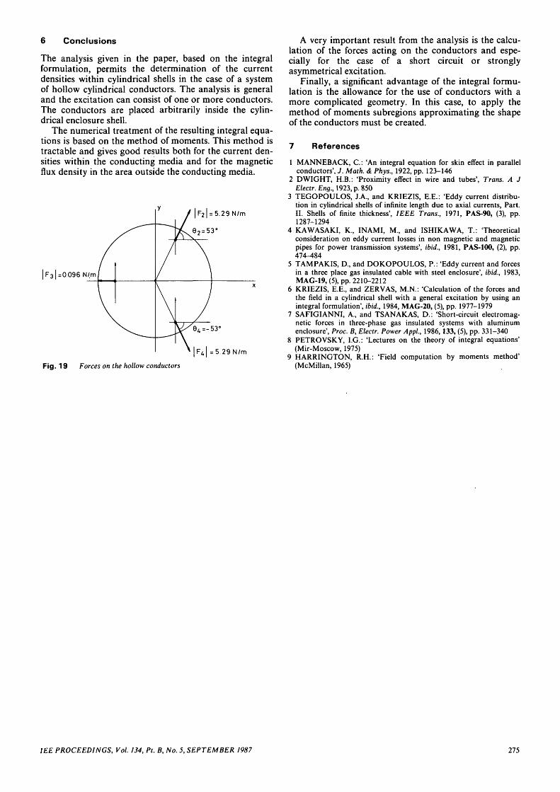
6 Conclusions
The analysis given in the paper, based on the integralformulation, permits the determination of the currentdensities within cylindrical shells in the case of a systemof hollow cylindrical conductors. The analysis is generaland the excitation can consist of one or more conductors.The conductors are placed arbitrarily inside the cylin-drical enclosure shell.
The numerical treatment of the resulting integral equa-tions is based on the method of moments. This method istractable and gives good results both for the current den-sities within the conducting media and for the magneticflux density in the area outside the conducting media.
| F31 =0.096 N/m
Fig. 19 Forces on the hollow conductors
A very important result from the analysis is the calcu-lation of the forces acting on the conductors and espe-cially for the case of a short circuit or stronglyasymmetrical excitation.
Finally, a significant advantage of the integral formu-lation is the allowance for the use of conductors with amore complicated geometry. In this case, to apply themethod of moments subregions approximating the shapeof the conductors must be created.
7 References
1 MANNEBACK, G: 'An integral equation for skin effect in parallelconductors', J. Math. & Phys., 1922, pp. 123-146
2 DWIGHT, H.B.: 'Proximity effect in wire and tubes', Trans. A JElectr. Eng., 1923, p. 850
3 TEGOPOULOS, J.A., and KRIEZIS, E.E.: 'Eddy current distribu-tion in cylindrical shells of infinite length due to axial currents, Part.II. Shells of finite thickness', IEEE Trans., 1971, PAS-90, (3), pp.1287-1294
4 KAWASAKI, K, INAMI, M., and ISHIKAWA, T.: 'Theoreticalconsideration on eddy current losses in non magnetic and magneticpipes for power transmission systems', ibid., 1981, PAS-100, (2), pp.474-484
5 TAMPAKIS, D., and DOKOPOULOS, P.: 'Eddy current and forcesin a three place gas insulated cable with steel enclosure', ibid., 1983,MAG-19, (5), pp. 2210-2212
6 KRIEZIS, E.E., and ZERVAS, M.N.: 'Calculation of the forces andthe field in a cylindrical shell with a general excitation by using anintegral formulation', ibid., 1984, MAG-20, (5), pp. 1977-1979
7 SAFIGIANNI, A., and TSANAKAS, D.: 'Short-circuit electromag-netic forces in three-phase gas insulated systems with aluminumenclosure', Proc. B, Electr. Power Appl., 1986,133, (5), pp. 331-340
8 PETROVSKY, I.G.: 'Lectures on the theory of integral equations'(Mir-Moscow, 1975)
9 HARRINGTON, R.H.: 'Field computation by moments method'(McMillan, 1965)
IEE PROCEEDINGS, Vol. 134, Pt. B, No. 5, SEPTEMBER 1987 275

IEEBOOKS
FROM THE IEESeries editors: Prof. A. T. Johns, G. Ratcliff, J. R. Platts
IEE
Electric railway systems for a new centuryIEE Conference Publication SeriesIncludes: Traction equipment for AC and DC Railways.AC and DC drives. Cooling and mechanical implica-tions. Control systems including microprocessors.Power supply. Voltage-controlled and inverting sub-stations for DC railways. Regeneration and energyrecovery. Protection and control. Performance andsystems studies. Energy consumption and cost. Lifecycle costing, availability and reliability. Signallingand communications. Optical fibre subsystems. Noiseand interference effects. Maintenance. Managementsystems including computer-based scheduling.Expected publication: Mid 1987
Industrial power engineeringIEE Conference Publication Number 272Includes: The birth of a board machine. Power suppliesfor industry. Testing and commissioning electricalpower systems. Planning and achieving electricalsafety. Steam turbines for industrial electrical genera-tion. Synchronous generators for furnace applications.The reliability of industrial circuit breaker panels.Sources and loads in industry. Sources and control ofmains distortion voltage.199pp., 39 papers, 297 x 210mm, soft coversISBN 0 85296 343 2, 1986 £30
Power electronics and variable-speed drivesIEE Conference Publication number 264Includes: Power semiconductors: Devices, protection,cooling drive circuits. Power electronics equipment:Switched mode power supplies, uninterruptible powersupplies. Variable-speed drives: Drives from an overallviewpoint, specifications, comparisons, design andperformance, operating experiences, applications,economic factors. Machines and power electronics: incombination, mutual effects, design and performance.252pp., 52 papers, 297 x 210mm, soft coversISBN 0 85296 341 6, 1986 £36
Power electronics and variable-speed drivesIEE Conference Publication number 234Includes: Power semiconductors, devices, protection,cooling, power electronic equipments, switched modeand uninterruptible power supplies, electroheat andelectrochemical applications, variable-speed drives,specifications, design and performance, environ-mental factors, radio interference, electromagneticpulse immunity.431pp., 100 papers, 297 x 210mm, soft coversISBN 0 85296 291 6, 1984 £51
Power diode and thyristor circuitsR. M. DavisDevice application practices. Basic rectifier circuits:centre-tap rectifiers, bridge rectifiers. Rectifier appli-cations, supplies and loads. Naturally commutatedinvertors and regulators. Capacitor turnoff: chopperregulators and series invertors. Parallel-capacitor-commutated invertors. Firing-control circuits.279pp., 210 x 150mm, paperbackISBN 0 901223 90 5, 1986 reprint edition £10
Electricity and buildingsG. J. Hughes (Ed)Principles of electricity. Electricity supplies. Electricalinstallation technology. Environmental principles andtechnology. Electricity in buildings.872pp., 229 x 148mm, caseboundISBN 0 86341 015 4, 1984 £64
Industrial microwave heatingA. C. Metaxas and R. J. MeredithDielectric properties. Theoretical aspects of volumetricheating. Travelling wave applicators. Multimode ovenapplicators. Single mode resonant cavities. Specialapplicator structures. Microwave heating circuit, break-down phenomena and vacuum processing. Hazards,leakage and safety. Industrial applications andeconomics.357pp., 229 x 148mm, paperbackISBN 0 906048 89 3, 1983 £45
Orders with remittances to: IEE, P.O. Box 26, Hitchin, Herts. SG5 1SA, U.K.
Prices include postage within the U.K. Outside the U.K., customers should add 10% of the total price to coverpostage by Bulk Air Mail to Europe. Outside Europe, 15% should be added to the price to cover postage byAccelerated Surface Post. Airmail rates are available on request. Credit card orders (Access and Visa) areconsidered prepaid and will be accepted by telephone on 0462 53331. Invoices for orders that are not prepaid willinclude a handling and package charge of £1.50 per book (maximum £6.00).
276 IEE PROCEEDINGS, Vol. 134, Pt. B, No. 5, SEPTEMBER 1987