integral force/moment waterjet model for cfd simulations
TRANSCRIPT

1
INTEGRAL FORCE/MOMENT WATERJET MODEL FOR CFD SIMULATIONS
Manivannan Kandasamy, Seng Keat Ooi, Pablo Carrica, Frederick Stern
IIHR-Hydroscience & Engineering
The University of Iowa
Iowa City, IA 52242
Abstract
An integral force/moment waterjet model for CFD is derived for ship local flow/powering
predictions, including sinkage and trim. The waterjet induced reaction forces and moment and
waterjet/hull interaction stern force replicate the effects of the waterjet without requiring detailed
simulations of the waterjet system. The model extends the ITTC waterjet model for sinkage and
trim by using an alternative control volume also appropriate for CFD and by including vertical
forces and pitching moment in the waterjet/hull force/moment balance. The same grid is used
for both without and with waterjet simulations. The CFD waterjet model requires limited
waterjet geometry (inlet and outlet areas and locations; and weight of working fluid) and several
waterjet flow (mass flow rate; inlet pressure force; inlet and outlet momentum correction factors
and flow angles; and stern force and location) input variables. The CFD waterjet model can be
used for local flow predictions by using waterjet flow input variables provided by ITTC waterjet
model test data, including additional data for waterjet induced inlet pressure and stern forces. It
can also be used for powering predictions once waterjet flow input variable correlations are
available based on CFD for the waterjet system and/or experimental data. The CFD waterjet
model is demonstrated for local flow predictions for the DTMB 5594 high-speed sealift ship
model for which ITTC waterjet model test data, including additional data for waterjet induced
stern forces are available. Correlations for the waterjet flow input variables are shown to be
feasible using combination of CFD and experimental data for the waterjet system for three
different hulls.
2
1. Introduction
Waterjet propulsion systems are increasingly being used for high-speed ships. Most CFD is for
the waterjet system alone without considering waterjet/hull interaction or powering prediction
due to the difficulty of geometry modeling and grid generation for the combined ship and
waterjet system, as reviewed by the Report of the 24th
ITTC Specialized Committee on
Validation of Waterjet Test Procedures [1]. Stern et al. [2] demonstrated CFD capability for
simulating waterjet self-propelled high-speed trimaran sealift ships including above water
discharge in both calm water and irregular head waves at sea state 6 conditions using CFDShip-
Iowa [3]. Kandasamy et al. [4] carried out detailed validation of the waterjet performance
predictions for the Joint High Speed Sea-Lift (JHSS). However, for some applications, details of
the waterjet induced flow are not required and a simplified force/moment waterjet model is
desirable, conceptually similar to that developed previously for propeller propulsion systems [5].
The current study was motivated by the need to model the waterjet’s effect on the trim of high-
speed, low-wake, semi-planning passenger ferries cost effectively during the initial design
stages, as the trim affects both the resistance and wake height significantly [6].
The ITTC [1] has developed waterjet test procedures, which combine model testing with control
volume/integral analysis for ship powering predictions hereafter referred to as ITTC waterjet
model. Herein, an integral force/moment waterjet model for CFD is derived for ship local
flow/powering predictions, including sinkage and trim. The waterjet induced reaction forces and
moment and waterjet/hull interaction stern force replicate the effects of the waterjet without
requiring detailed simulations of the waterjet system. The model extends the ITTC waterjet
model for sinkage and trim by using an alternative control volume also appropriate for CFD and
by including vertical forces and pitching moment in the waterjet/hull force/moment balance. The
same grid is used for both without and with waterjet simulations. The CFD waterjet model
requires limited waterjet geometry (inlet and outlet areas and locations; and weight of working
fluid) and several waterjet flow (mass flow rate; inlet pressure force; inlet and outlet momentum
correction factors and flow angles; and stern force and location) input variables. The CFD
waterjet model can be used for local flow and sinkage and trim predictions by using waterjet
flow input variables provided by ITTC waterjet model test data, including additional data for

3
waterjet induced inlet pressure and stern forces. It can also be used for powering predictions
once waterjet flow input variable correlations are available based on CFD for the waterjet system
and/or experimental data. The CFD waterjet model is demonstrated for local flow predictions
for the DTMB 5594 high-speed sealift ship model for which ITTC waterjet model test data,
including additional data for waterjet induced stern forces are available. Correlations for the
waterjet flow input variables are shown to be feasible using CFD for the waterjet system for
three different hulls.
2. ITTC Waterjet Model
The ITTC waterjet model combines model testing with control volume/integral analysis for ship
powering predictions. Such procedures are required due to difficulties for direct measurement of
the waterjet net thrust.
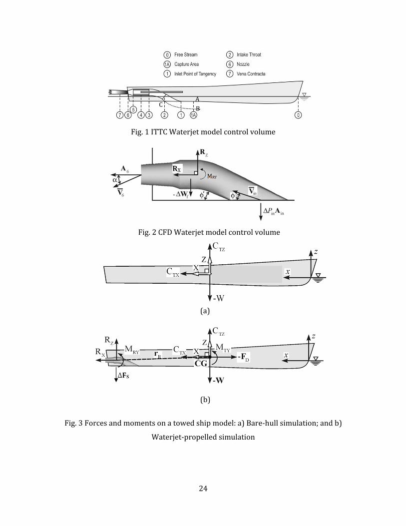
The ITTC waterjet model control volume set in the carriage-fixed inertial frame of reference,
shown in Fig. 1, was selected for the waterjet system in order to be able to compute or determine
the powering characteristics from measurements, with consideration to (1) ease of measurement
of momentum and energy fluxes across inlet and outlet, (2) control volume boundaries capture
all inflow and outflow of waterjet system, and (3) the protruding part of the control volume
defined by surface ABC should be as small as possible to avoid strong interaction effects with
the external flow. The selected control volume is defined by a streamtube consisting of the
nozzle, pump, ducting system, inlet, and upstream imaginary surface BC in the flow through
which it is assumed no mass transport occurs by definition with one outlet A6 and inlet A1A.
Vertical reaction force, weight of the working fluid, and pressure and shear forces acting on BC
are neglected. The inlet A1A is selected to avoid major flow distortions by the intake geometry
and as practical choice is usually one impeller diameter in front of the ramp tangency point.
The ITTC model procedures provide a series of standardized tests for the prediction of the main
powering characteristics such as power-speed and impeller rotation rate-speed relation. The
procedures are presented in global terms leaving sufficient freedom for individual institutes to

4
use their own preferred methods. The first step is the collection of data such as nozzle area, A6,
hull length Lpp and static wetted surface area AS.
The second step is the resistance test and wake-field measurements where a resistance test is
carried out for a bare hull model with closed intakes that is free to sink and trim. The total bare
hull resistance RTBH is obtained and is used later to estimate the thrust deduction factor, t. During
the resistance test the boundary layer velocity profile u1AX(y,z) is measured at Station 1A. This
profile will be used later to calculate the following items: the intake area at station 1A, the
average velocity at station 1A, 𝑉 1𝐴, and the momentum correction factor at Station 1A, cm1,
which is calculated at any station N using Eq. (1-2)
𝑐𝑀𝑁 =1
𝐴𝑁
𝑢
𝑉 𝑁
2
𝐴𝑁
𝑑𝐴
𝑉 𝑁 =1
𝐴𝑁 (𝑽.𝒏)
𝐴𝑁
𝑑𝐴
The third step is the calibration and propulsion test. The purpose of the calibration test is to
establish a relation between a measurement signal at the jet (often a differential pressure
transducer or Kiel probe is used) and the jet-thrust (TJx) which is measured through the Bollard
pull test. The flow rate (Q) is then calibrated through the momentum flux approach, since direct
measurement of flow-rate is prone to higher uncertainties. Assuming negligible inlet axial
velocity, TJx is equal to the momentum flux at the jet nozzle providing Eq. (3) for estimating Q.
𝑄 = 𝑇𝐽𝑥𝐴6
𝜌𝑐𝑚6𝑐𝑜𝑠𝛼
During the calibration phase, the momentum correction factor at the jet exit cm6 is obtained from
detailed jet velocity profiles using LDV. α is the jet angle relative to the horizontal at the nozzle
(station 6). This calibration is assumed to hold good even with non-zero forward velocity, so that
the Kiel probe measurements taken during self-propulsion tests could be used to estimate Q.
(1)
(2)
(3)

5
After calibration, the propulsion test is carried out to determine relation between speed, flow-rate
and thrust at self propulsion point. Note that the ITTC model procedure recommends that the
self-propulsion point be determined through thrust identity which requires that the non-
dimensional thrust loading be the same in both full and model scale. The model must then be
towed with a make-up added tow force to account for the higher friction in model scale due to
the thicker boundary layer which is defined as
2
0
1
2D Fm FsF U S C C (4)
where Uo is the desired model velocity, S is the model wetted surface area, CFm and CFs are the
model and ship friction coefficients, calculated from the ITTC ship-model correlation.
The calibrated Kiel probe measurements provide Q at the self-propulsion point. Q is then used to
determine the size of the inlet capture area from the inlet wake-field measurements by applying
conservation of mass. Once the capture area is determined cm1 can be calculated. All the relevant
variables to predict the waterjet net thrust (RX) from Eq. (5) are now known.
−𝑅𝑋 =𝜌𝑄
2
𝐴6𝑐𝑀6𝑐𝑜𝑠𝛼 − 𝜌𝑄 𝑐𝑀𝑖𝑛𝑈𝑜
Which can alternatively be written as in Eq. (6)
𝑅𝑋 = −𝑚( 𝑐𝑀6𝑉 6𝑋𝑐𝑜𝑠𝛼 − 𝑐𝑀𝑖𝑛𝑉 𝑖𝑛𝑋 )
Notice that the ITTC model ignores vertical forces and pitching moments needed to evaluate
sinkage and trim in a CFD simulation. These are not relevant for the purposes of the original
ITTC model, since sinkage and trim are measured during the thrust evaluation procedure. For a
CFD simulation, however, it is desirable to estimate the resulting waterjet-induces forces and
moments affecting sinkage and trim, since the final attitude of the ship affects the resistance and
wave-generation characteristics of the ship.
(5)
(6)
6
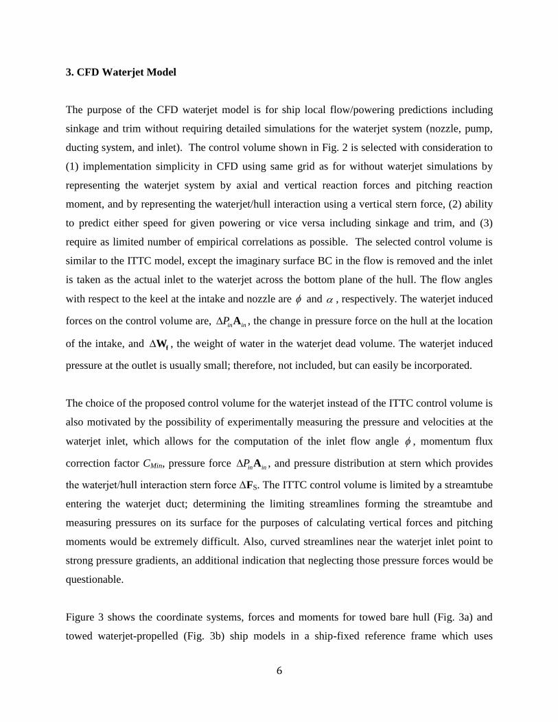
3. CFD Waterjet Model
The purpose of the CFD waterjet model is for ship local flow/powering predictions including
sinkage and trim without requiring detailed simulations for the waterjet system (nozzle, pump,
ducting system, and inlet). The control volume shown in Fig. 2 is selected with consideration to
(1) implementation simplicity in CFD using same grid as for without waterjet simulations by
representing the waterjet system by axial and vertical reaction forces and pitching reaction
moment, and by representing the waterjet/hull interaction using a vertical stern force, (2) ability
to predict either speed for given powering or vice versa including sinkage and trim, and (3)
require as limited number of empirical correlations as possible. The selected control volume is
similar to the ITTC model, except the imaginary surface BC in the flow is removed and the inlet
is taken as the actual inlet to the waterjet across the bottom plane of the hull. The flow angles
with respect to the keel at the intake and nozzle are and , respectively. The waterjet induced
forces on the control volume are, in inP A , the change in pressure force on the hull at the location
of the intake, and fW , the weight of water in the waterjet dead volume. The waterjet induced
pressure at the outlet is usually small; therefore, not included, but can easily be incorporated.
The choice of the proposed control volume for the waterjet instead of the ITTC control volume is
also motivated by the possibility of experimentally measuring the pressure and velocities at the
waterjet inlet, which allows for the computation of the inlet flow angle , momentum flux
correction factor CMin, pressure force in inP A , and pressure distribution at stern which provides
the waterjet/hull interaction stern force ΔFS. The ITTC control volume is limited by a streamtube
entering the waterjet duct; determining the limiting streamlines forming the streamtube and
measuring pressures on its surface for the purposes of calculating vertical forces and pitching
moments would be extremely difficult. Also, curved streamlines near the waterjet inlet point to
strong pressure gradients, an additional indication that neglecting those pressure forces would be
questionable.
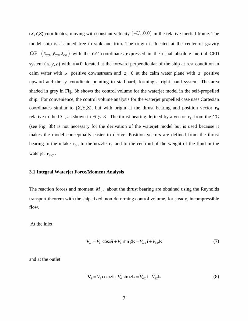
Figure 3 shows the coordinate systems, forces and moments for towed bare hull (Fig. 3a) and
towed waterjet-propelled (Fig. 3b) ship models in a ship-fixed reference frame which uses
7
(X,Y,Z) coordinates, moving with constant velocity 0 ,0,0U in the relative inertial frame. The
model ship is assumed free to sink and trim. The origin is located at the center of gravity
, ,CG CG CGCG x y z with the CG coordinates expressed in the usual absolute inertial CFD
system ( , ,x y z ) with 0x located at the forward perpendicular of the ship at rest condition in
calm water with x positive downstream and 0z at the calm water plane with z positive
upward and the y coordinate pointing to starboard, forming a right hand system. The area
shaded in grey in Fig. 3b shows the control volume for the waterjet model in the self-propelled
ship. For convenience, the control volume analysis for the waterjet propelled case uses Cartesian
coordinates similar to (X,Y,Z), but with origin at the thrust bearing and position vector rR
relative to the CG, as shown in Figs. 3. The thrust bearing defined by a vector Rr from the CG
(see Fig. 3b) is not necessary for the derivation of the waterjet model but is used because it
makes the model conceptually easier to derive. Position vectors are defined from the thrust
bearing to the intake inr , to the nozzle 6r and to the centroid of the weight of the fluid in the
waterjet Wfr .
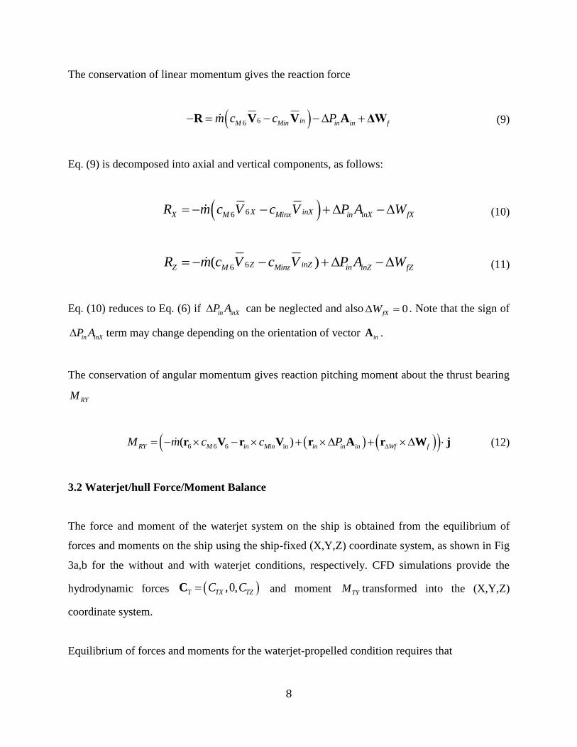
3.1 Integral Waterjet Force/Moment Analysis
The reaction forces and moment RYM about the thrust bearing are obtained using the Reynolds
transport theorem with the ship-fixed, non-deforming control volume, for steady, incompressible
flow.
At the inlet
cos sinin in in inX inZV V V V V i k i k (7)
and at the outlet
6 6 6 6 6cos sin X ZV V V V V i k i k (8)
8
The conservation of linear momentum gives the reaction force
66 inM Min in in fm c c P R V V A ΔW (9)
Eq. (9) is decomposed into axial and vertical components, as follows:
66 X inXX M Minx in inX fXR m c V c V P A W (10)
66( )Z inZZ M Minz in inZ fZR m c V c V P A W (11)
Eq. (10) reduces to Eq. (6) if in inXP A can be neglected and also 0fXW . Note that the sign of
in inXP A term may change depending on the orientation of vector inA .
The conservation of angular momentum gives reaction pitching moment about the thrust bearing
RYM
6 6 6 in( )RY M in Min in in in Wf fM m c c P r V r V r A r W j (12)
3.2 Waterjet/hull Force/Moment Balance
The force and moment of the waterjet system on the ship is obtained from the equilibrium of
forces and moments on the ship using the ship-fixed (X,Y,Z) coordinate system, as shown in Fig
3a,b for the without and with waterjet conditions, respectively. CFD simulations provide the
hydrodynamic forces T ,0,TX TZC CC
and moment TYM transformed into the (X,Y,Z)
coordinate system.
Equilibrium of forces and moments for the waterjet-propelled condition requires that

9
cos sin 0X TX X SX DF C R F F W (13)
cos sin 0Z TZ Z SZ DF C R F W F (14)
0Y RY R FS S TYM M M r R j r F j (15)
DF is the added tow force in the axial direction of the carriage, W is the weight of the ship,
( ,0, )FS FS FSX Z r is the position vector from the CG to ΔFS, and τ is the trim angle. Expanding
Eq. (15) results in
0Y WJ TYM M M (16)
where
WJ RY R X R Z FS SX FS SZM M Z R X R Z F X F (17)
Eqs. (13) to (17) can also be used for the towed bare hull simulations by setting all the waterjet
forces , , ,X Z SX SZR R F F , moments RYM , WJM and position vectors ,FS Rr r in the equations to
zero.
In summary, the CFD waterjet model includes vertical reaction force, weight of the working
fluid, pressure forces acting on the inlet, and pitching moment. Additionally, the waterjet/hull
interaction is represented by a waterjet induced stern force, which is included in the waterjet/hull
force/moment balance. The input variables required are: for geometry 6,inA A , Rr , inr , 6r , Wfr ,
and fW ; and for waterjet flow m , in inP A , Minc , 6Mc , ϕ, α, and SF . For current validation of
the waterjet model, these input variables are acquired from experiments on DTMB 5594. The
feasibility of acquiring these input variables from correlations is discussed in Section 6.
10
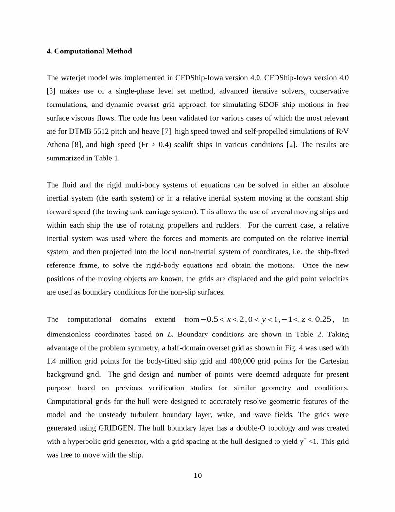
4. Computational Method
The waterjet model was implemented in CFDShip-Iowa version 4.0. CFDShip-Iowa version 4.0
[3] makes use of a single-phase level set method, advanced iterative solvers, conservative
formulations, and dynamic overset grid approach for simulating 6DOF ship motions in free
surface viscous flows. The code has been validated for various cases of which the most relevant
are for DTMB 5512 pitch and heave [7], high speed towed and self-propelled simulations of R/V
Athena [8], and high speed (Fr > 0.4) sealift ships in various conditions [2]. The results are
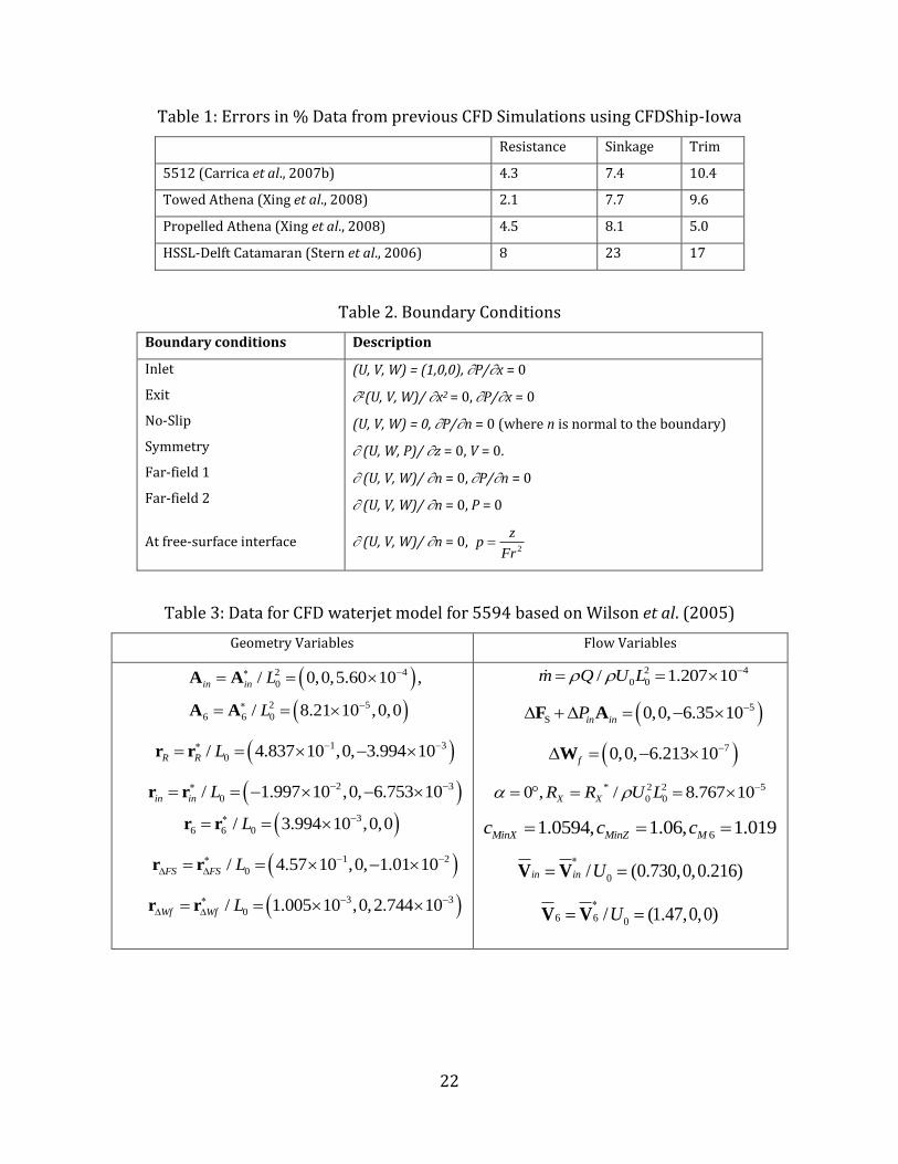
summarized in Table 1.
The fluid and the rigid multi-body systems of equations can be solved in either an absolute
inertial system (the earth system) or in a relative inertial system moving at the constant ship
forward speed (the towing tank carriage system). This allows the use of several moving ships and
within each ship the use of rotating propellers and rudders. For the current case, a relative
inertial system was used where the forces and moments are computed on the relative inertial
system, and then projected into the local non-inertial system of coordinates, i.e. the ship-fixed
reference frame, to solve the rigid-body equations and obtain the motions. Once the new
positions of the moving objects are known, the grids are displaced and the grid point velocities
are used as boundary conditions for the non-slip surfaces.
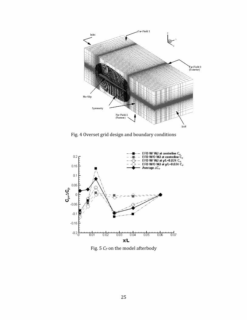
The computational domains extend from 25.0 x , 10 y , 25.01 z , in
dimensionless coordinates based on L. Boundary conditions are shown in Table 2. Taking
advantage of the problem symmetry, a half-domain overset grid as shown in Fig. 4 was used with
1.4 million grid points for the body-fitted ship grid and 400,000 grid points for the Cartesian
background grid. The grid design and number of points were deemed adequate for present
purpose based on previous verification studies for similar geometry and conditions.
Computational grids for the hull were designed to accurately resolve geometric features of the
model and the unsteady turbulent boundary layer, wake, and wave fields. The grids were
generated using GRIDGEN. The hull boundary layer has a double-O topology and was created
with a hyperbolic grid generator, with a grid spacing at the hull designed to yield y+ <1. This grid
was free to move with the ship.
11
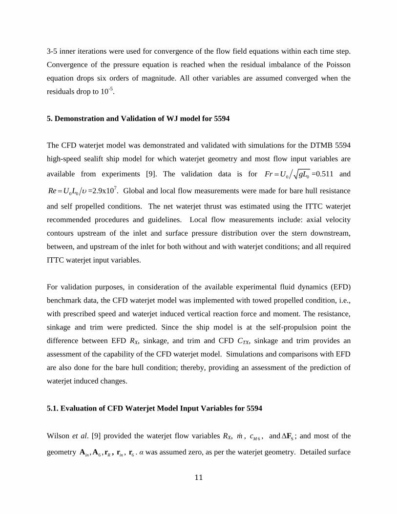
3-5 inner iterations were used for convergence of the flow field equations within each time step.
Convergence of the pressure equation is reached when the residual imbalance of the Poisson
equation drops six orders of magnitude. All other variables are assumed converged when the
residuals drop to 10-5
.
5. Demonstration and Validation of WJ model for 5594
The CFD waterjet model was demonstrated and validated with simulations for the DTMB 5594
high-speed sealift ship model for which waterjet geometry and most flow input variables are
available from experiments [9]. The validation data is for 0 0Fr U gL =0.511 and
0 0Re U L =2.9x10⁷. Global and local flow measurements were made for bare hull resistance
and self propelled conditions. The net waterjet thrust was estimated using the ITTC waterjet
recommended procedures and guidelines. Local flow measurements include: axial velocity
contours upstream of the inlet and surface pressure distribution over the stern downstream,
between, and upstream of the inlet for both without and with waterjet conditions; and all required
ITTC waterjet input variables.
For validation purposes, in consideration of the available experimental fluid dynamics (EFD)
benchmark data, the CFD waterjet model was implemented with towed propelled condition, i.e.,
with prescribed speed and waterjet induced vertical reaction force and moment. The resistance,
sinkage and trim were predicted. Since the ship model is at the self-propulsion point the
difference between EFD RX, sinkage, and trim and CFD CTX, sinkage and trim provides an
assessment of the capability of the CFD waterjet model. Simulations and comparisons with EFD
are also done for the bare hull condition; thereby, providing an assessment of the prediction of
waterjet induced changes.
5.1. Evaluation of CFD Waterjet Model Input Variables for 5594
Wilson et al. [9] provided the waterjet flow variables RX, m , 6Mc , and SF ; and most of the
geometry 6,inA A , Rr , inr , 6r . α was assumed zero, as per the waterjet geometry. Detailed surface
12
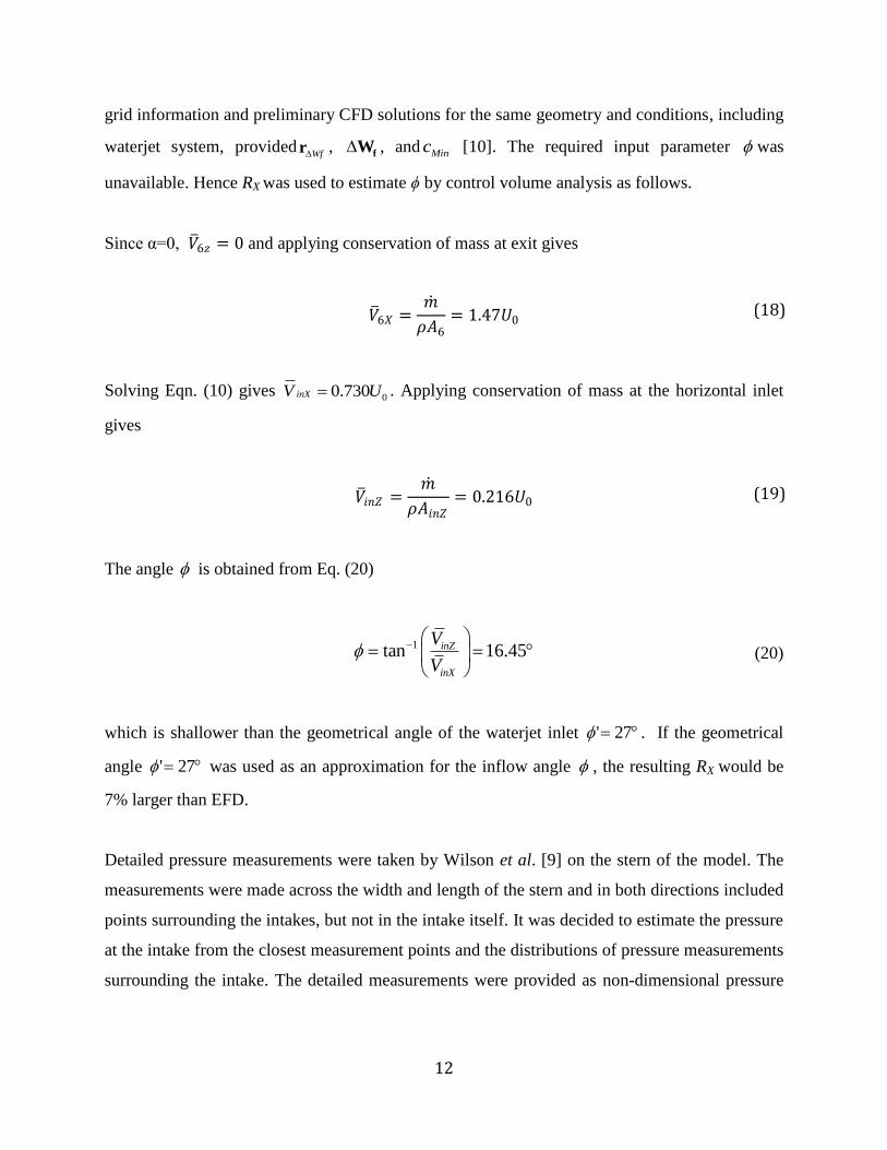
grid information and preliminary CFD solutions for the same geometry and conditions, including
waterjet system, providedWfr ,
fW , and Minc [10]. The required input parameter was
unavailable. Hence RX was used to estimate ϕ by control volume analysis as follows.
Since α=0, 𝑉 6𝑧 = 0 and applying conservation of mass at exit gives
𝑉 6𝑋 =𝑚
𝜌𝐴6
= 1.47𝑈0
Solving Eqn. (10) gives 00.730inXV U . Applying conservation of mass at the horizontal inlet
gives
𝑉 𝑖𝑛𝑍 =𝑚
𝜌𝐴𝑖𝑛𝑍
= 0.216𝑈0
The angle is obtained from Eq. (20)
1tan 16.45inZ
inX
V
V
(20)
which is shallower than the geometrical angle of the waterjet inlet 27' . If the geometrical
angle 27' was used as an approximation for the inflow angle , the resulting RX would be
7% larger than EFD.
Detailed pressure measurements were taken by Wilson et al. [9] on the stern of the model. The
measurements were made across the width and length of the stern and in both directions included
points surrounding the intakes, but not in the intake itself. It was decided to estimate the pressure
at the intake from the closest measurement points and the distributions of pressure measurements
surrounding the intake. The detailed measurements were provided as non-dimensional pressure
(19)
(18)
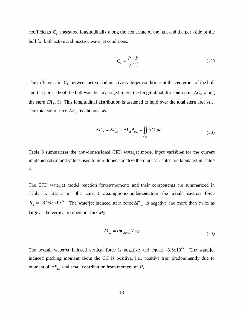
13
coefficients PC measured longitudinally along the centerline of the hull and the port-side of the
hull for both active and inactive waterjet conditions.
2P
o
P PC
U
(21)
The difference in PC between active and inactive waterjet conditions at the centerline of the hull
and the port-side of the hull was then averaged to get the longitudinal distribution of PC along
the stern (Fig. 5). This longitudinal distribution is assumed to hold over the total stern area ATZ.
The total stern force TZF is obtained as
TZ
TZ SZ in inZ P
A
F F P A C da (22)
Table 3 summarizes the non-dimensional CFD waterjet model input variables for the current
implementation and values used to non-dimensionalize the input variables are tabulated in Table
4.
The CFD waterjet model reaction forces/moments and their components are summarized in
Table 5. Based on the current assumptions/implementation the axial reaction force
58.767 10XR . The waterjet induced stern force TZF is negative and more than twice as
large as the vertical momentum flux MZ.
inZZ MinZM mc V
(23)
The overall waterjet induced vertical force is negative and equals -3.6x10⁻⁵
. The waterjet
induced pitching moment about the CG is positive, i.e., positive trim predominantly due to
moment of TZF and small contribution from moment of XR .
14
5.2 Validation of Global Variables
Simulations were conducted for both towed barehull and towed propelled conditions and the
resistance, sinkage, and trim were predicted. The error in predicted total resistance (CTX) for the
towed bare hull simulation (Table 6) is E=0.78%, where the relative error E is defined as
E(%D)=(EFD-CFD)/EFD ×100. The error in sinkage is E=0.8% and trim is 14.3%. The errors
are within the range of error values obtained from this code in previous simulations (Table 1).
For the towed propelled simulations the error for resistance, sinkage and trim are -4.6%, 9.0%,
and 13.6%, respectively.
Waterjet induced changes in sinkage and trim were estimated using hydrostatics approximations
[11]. The hydrostatic heave restoring force is written as the incremental heave for an incremental
restoring force:
Z WPR gA (24)
where is the induced sinkage due to the waterjet, is the density of water and
2 2
00.0509 2.4631WPA L m is the waterplane area [10]. The standard moment to trim one
degree was modified to account for any small incremental angle instead of one degree. This
results in the following expression
1sin WJ LM gI (25)
where is the waterjet induced change in trim angle, LI is the longitudinal moment of inertia
about the center of flotation. The results are summarized in Table 7.
Table 7 includes CFD predictions of waterjet induced sinkage and trim. The E=-58%D and
11.5%D for and are larger than the hydrostatic estimates. Table 7 also shows the relative
induced change in sinkage / BH and trim / BH which serves as a better measure of the
waterjet/hull interaction than and . The towed bare hull CFD simulation values of

15
sinkage BH and trim BH are used in the computation of / BH and / BH for the CFD
predictions. The CFD waterjet model under predicts / BH as / 7.01%BH compared to
the EFD value of 16.97% , for / BH the CFD waterjet model predictions are reasonable as
/ 25.51%BH compared to / 24.57%BH reported by EFD.
The large relative induced change in sinkage and trim show that the waterjet/hull interaction is
significant. However, because the absolute magnitudes of the induced sinkage and trim are small,
the change in resistance between the towed bare-hull and towed propelled models at the same
speed is small. This result indicates that for this displacement ship at this Froude number the
change in sinkage and trim due to the waterjet/hull interaction will not affect speed significantly
for the same power.
5.3 Validation of Local Variables
The primary purpose of implementing the waterjet model using waterjet model input data from
experiments is that flow details like boundary layer profiles, bow/sonar-dome vortices, and wave
elevations, which are expensive to obtain from experiments, can be obtained through the
simulations. This is especially true when farfield wave elevation are required, which in some
cases are highly sensitive to waterjet induced changes in trim angle. Wave elevation data is
unavailable for the 5594 self propelled cases. Here, the predictive capability of CFDShip for
local flow variables is demonstrated in Fig. 6, which shows the nominal wake contours of the
non-dimensional axial velocity immediately upstream of the waterjet inlet (x/L=0.93) with the
inlets closed and the model towed at a fixed sinkage and trim condition equal to that of the self-
propelled case. The CFD contours show a good agreement with the EFD [9], with a slight over
prediction of the boundary layer thickness.
6. Correlations for CFD Waterjet Model
Ultimately, the waterjet model will be of most use if general correlations can be obtained, which
would provide the water-jet flow input variables. Recently, detailed self-propulsion simulation
16
of waterjet appended ships have been performed, which provide opportunity to investigate if
such correlations are feasible. Kandasamy et al. [4] provide detailed self propulsion simulation
results for waterjet appended Joint High Speed Sea-lift (JHSS). The results were validated using
experimental data [12]. In addition, simulation results are also available for Delft catamaran
(DC) for which experimental results for validation are available from ongoing ONR
collaborative project with Bulgarian Ship Hydrodynamics Centre [13]. In this section, we
explore the possibility of obtaining suitable correlations from self propulsion simulations for
JHSS and DC, along with the experimental data available for 5594.
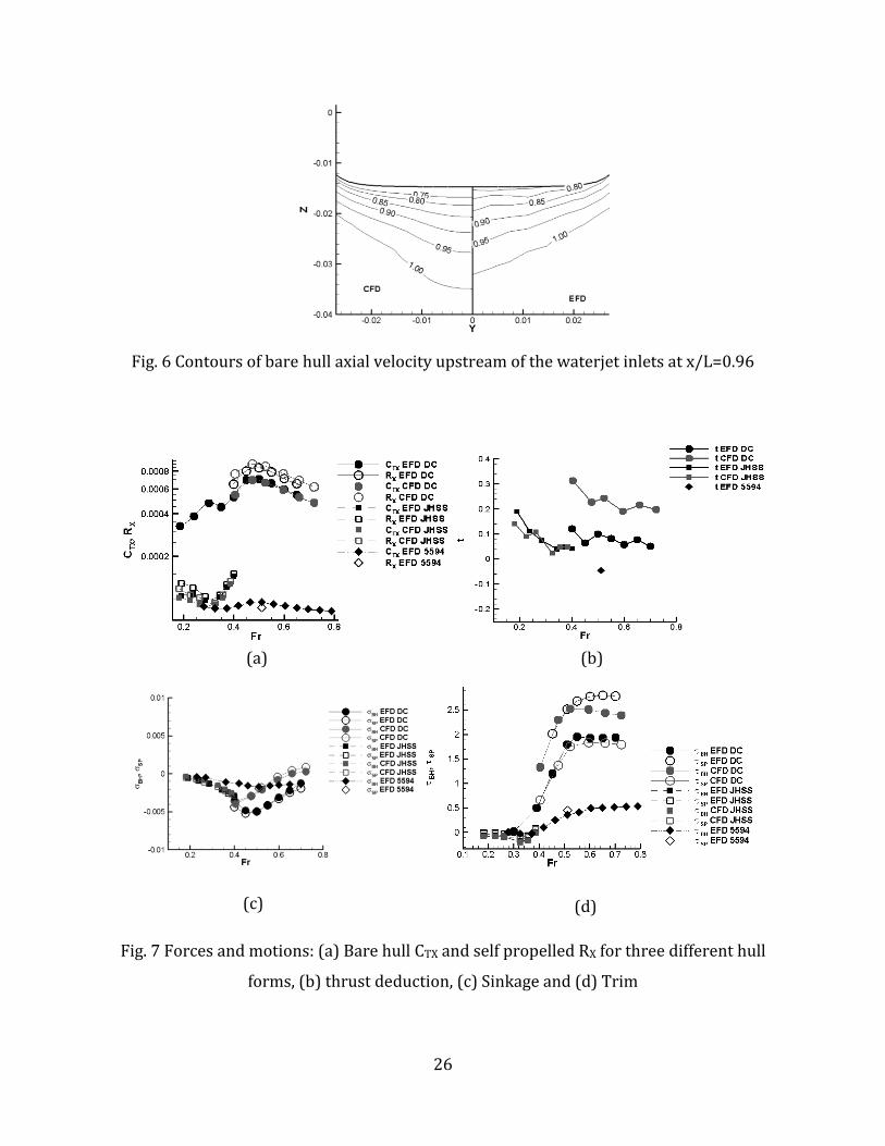
Figure 7a shows the barehull resistance CTX and self propelled net jet thrust RX for both the
experiments and the simulations. Detailed waterjet self-propelled simulation results are available
in the range 0.18 < Fr < 0.39 for JHSS and 0.46 < Fr < 0.80 for DC, along with validation data.
Barehull validation data is available for DC over a wider range 0.20 < Fr < 0.70. RX is available
for 5594 only at Fr=0.511, and CTX is available over the whole range 0.20 < Fr < 0.80. From the
simulation results, RX for JHSS and DC was obtained using the CFD waterjet model control
volume and is within ±2% of the values obtained using the ITTC control volume. A log scale is
used in the plots since CTX and RX values for DC are up to an order of magnitude higher than
JHSS and 5594 for the following reasons: 1) The non-dimensionalization parameter is L2, and
being a catamaran in addition to having a lower demihull slenderness ratio than the other two
hulls, the wetted surface area to L2 ratio for DC is almost four times larger than JHSS and 5594
and 2) the values for DC are at model scale, whereas JHSS and 5594 were investigated with full-
scale thrust identity and added tow force. In Fig. 7a, the added tow force has been subtracted
from the barehull CTX for JHSS and 5594 to enable comparison with RX and for the calculation of
thrust deduction fraction t.
For DC, CTX and RX are within 3.9% and 9% of the benchmark data, respectively. For JHSS, CTX
and RX are within 6.2% and 7.1% of the data, respectively. Both DC and 5594 show the
characteristic CTX hump at Fr~0.5, but it is more prominent for DC. Data is not available for
JHSS at the hump region. The simulations show a reasonably good agreement with data for the
thrust deduction fraction t (Fig. 7b). The experiments show a negative thrust deduction for 5594
at Fr=0.51; simulations are not available for this condition. Figure 7c shows the sinkage for the
17
different hulls. For both DC and JHSS, simulations and experiments show negligible effect of the
waterjet on the sinkage, and the simulation results corresponds well with the data. The waterjet
induced increase in trim (Fig. 7d) is highest for DC, moderate for 5594, and comparatively
negligible for JHSS. The simulation and experimental trim values compares well for both DC
and JHSS.
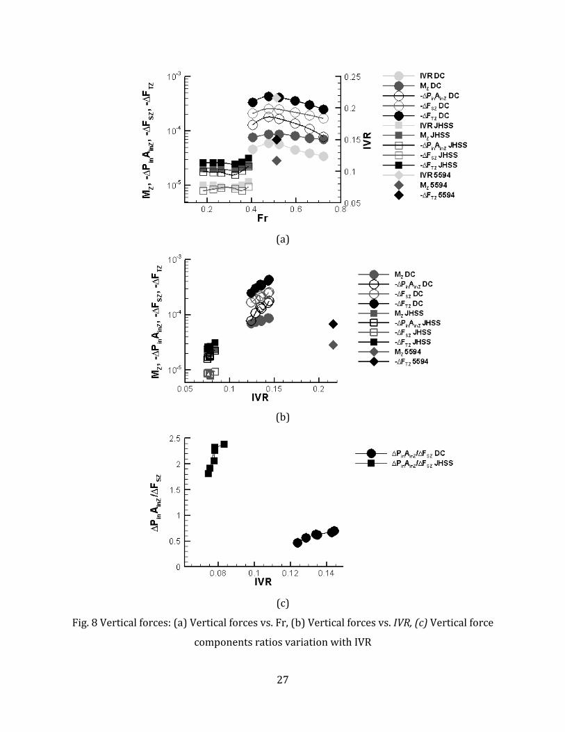
The transom vertical force components for the different hulls over the Fr range shown in Fig. 8a
show similar trends as RX in Fig. 7a. DC vertical forces are almost an order of magnitude greater
than JHSS and 5594, and peak at Fr~0.5, similar to RX. For JHSS, both the vertical forces and RX
indicate a gradual rise after Fr=0.3. The inlet velocity ratio (IVR), which is 𝑉 𝐴𝑖𝑛 from Eq. (2)
normalized by the free stream velocity U0 is plotted alongside and also shows similar trends as
the vertical force components. Plotting the vertical forces against the IVR (Fig. 8b) indicates a
noticeable log-linear trend between the vertical forces and IVR for both JHSS and DC. Since the
vertical forces for DC is about an order of magnitude greater than the other two hulls, a
generalized correlation between the vertical force components and the IVR that can encompass
all the hulls is unattainable. Fig. 8c shows the relative contributions of ∆PinAinZ and ∆FSZ by
plotting the ratio ∆PinAinZ/∆FSZ against IVR. The differences in the waterjet inlet and hull designs
account for the dominance of ∆PinAinZ component in JHSS and ∆FSZ component in DC. For both
hulls, the contribution of ∆PinAinZ component increases with increasing IVR.
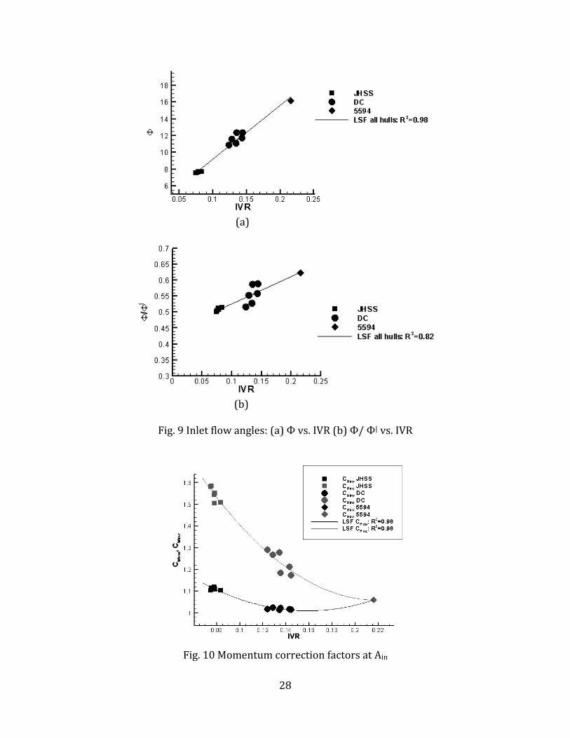
Fig. 9a and 9b give the variation of ϕ and ϕ/ϕ/ vs. IVR, respectively. A linear least square fit
(LSF) over the data for ϕ over all the points is possible with a correlation coefficient (R2) of 0.98.
The variation in ϕ/ϕ/ is small, between 0.5 - 0.6, for the different ships over the IVR range and a
linear LSF gives R2=0.82. Fig. 10 shows the momentum correction factors the waterjet inlet vs.
IVR. A LSF with a second order polynomial gives R2 values of 0.98 for both CMinX and CMinZ.
CM6 at outlet is almost constant ~ 1.03±2%.
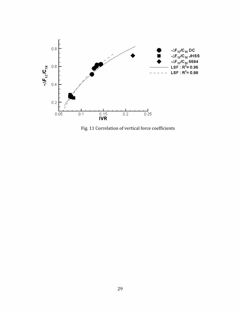
Noting that both CTX and -FTZ for DC are almost an order of magnitude higher than the other two
hulls, a general correlation for the vertical forces to encompasses all the different hull/waterjet
designs seems possible, by plotting the ratio -FTZ/CTX against IVR (Fig. 11). This ratio is similar
to the lift/drag coefficients used in aerospace engineering. CTX is used here instead of RX, since
18
RX will be unavailable during implementation of the waterjet model for predictive purposes. A
logarithmic LSF fit over all the hulls is possible with R2=0.95. Note that ∆PinAinZ for 5594 was
approximated by the closest pressure measurements at the stern and is not an accurate
representation of its true value as evident from Fig. 8c. A logarithmic LSF fit with R2=0.98 is
possible if only JHSS and DC are considered.
These correlations provide all the waterjet inlet flow variables as a function of IVR. Eq. 10 can
be re-written as functions of IVR as follows
2
6
6
( ) ( cot )inZX inZ M MinX
X
AR fn IVR IVR A c c
A (26)
As an initial guess, the waterjet geometric angle information can be used to get an estimate of
the inflow angle assuming inflow/geometric angle ratio~0.55. The corresponding IVR is obtained
from Fig. 10b. For a particular Fr, based on CTX and the initial IVR estimates, the total vertical
stern force is calculated using the correlation from Fig. 11, which provides ∆𝐹𝑇𝑍 and the vertical
momentum flux term is obtained as
2
Z inZ MinZM IVR A c (27)
A towed propelled simulation can be conducted at the particular Fr to obtain a new RX. IVR is
then recalculated from Eq.26. cMinZ is recalculated for the new IVR, and MZ is obtained from
Eq.27. The vertical forces are recalculated based on the new IVR from Fig. 11, and the steps are
iterated until convergence.
6. CONCLUSIONS
An integral force/moment waterjet model for CFD is derived for ship local flow/powering
predictions, including sinkage and trim. The CFD waterjet model is derived in a ship-fixed
reference frame and extends the ITTC waterjet model by using a control volume appropriate for
CFD, which includes vertical forces RZ and angular momentum MRY. In addition, the model

19
accounts for the waterjet-hull interaction by incorporating a stern force ∆FS in the balance of
forces and moments for the ship. This allows the CFD waterjet model to predict sinkage and trim
in addition to resistance for waterjet-propelled ships without requiring detailed modeling of the
waterjet geometry.
The model is demonstrated and validated using existing data from towing tank experiments of a
towed bare-hull and towed propelled DTMB 5594 using RX from EFD as an input parameter to
estimate , which was not measured. The effects of the model on sinkage and trim are
qualitatively examined using hydrostatics. The hydrostatic estimates show good agreement with
experimental data. The model is then implemented in a CFD code, CFDShip-Iowa 4.0. A
baseline CFD simulation is carried out mimicking the towed bare hull condition, showing good
quantitative agreement with EFD results especially with regards to resistance, E =0.78%, and
sinkage, E=0.8%, and reasonably good agreement for trim, E=14.3%. The CFD waterjet model is
shown to be reasonably accurate in predicting resistance, E<5%, sinkage, E=9.0%, and trim,
E=13.7%, as the errors are comparable in magnitude to previous simulations using the code.
However, the thrust deduction fraction t from the simulations is positive whereas the data
indicate negative t. Such application of the model will be useful for prediction of local flow
variables which are difficult to measure in experiments. The ITTC procedures which already
require extensive data collection could be extended to measure the input variables required for
the CFD waterjet model. Pressure measurements at the inlet would allow for separately
specifying in inP A and ΔFS, instead of approximating in inP A using the pressure at the vicinity of
the inlet as was done for the current validation.
The model can also be used for powering predictions once waterjet flow input variable
correlations are available based on CFD for the waterjet system and/or experimental data.
Detailed waterjet flow simulation results from JHSS and DC were used along with available data
for DTMB 5594 to derive correlations for the waterjet model input variables. Correlations
obtained from this limited analysis indicate that this approach is feasible. However, additional
detailed simulations and experiments for different waterjet/hull geometries over a wide range of
operating conditions need to be investigated before such correlations can be fully established.

20
ACKNOWLEDGMENTS
This research is sponsored by Pacific International Engineering PLLC contract # KT-05-343
under the administration of Dr. Philip D. Osborne and the Office of Naval Research grant
N00014-08-1-0491 under the administration of Dr. Ki-Han Kim.
REFERENCES
[1] Van Terwisga, T. (Chairman), 2005, "Report of the Specialist Committee on Validation of
Waterjet Test Procedures," Proceedings 24th
Int. Towing Tank Conference, II, pp. 471-508.
[2] Stern, F., Carrica, P., Kandasamy, M., Gorski, J., O’Dea, J., Hughes, M., Miller, R., Kring,
D., Milewski, W., Hoffman, R., and Cary, C., 2007, "Computational Hydrodynamic Tools
for High-Speed Sealift," Transactions SNAME, 114, pp. 55-81.
[3] Carrica, P.M., Wilson, R.V., and Stern, F., 2007, "An Unsteady Single-Phase Level Set
Method for Viscous Free Surface Flows," Int. J. Numer. Meth. Fluids, 53, pp. 229-256.
[4] Kandasamy, M., Takai, T., and Stern, F., 2009, "Validation of Detailed Waterjet Simulation
using URANS for Large High-Speed Sea-Lifts," 10th International Conference on Fast Sea
Transportation, Athens, Greece: October 5 – 8.
[5] Stern, F., Kim, H.T., Zhang, D.H., Toda, Y, Kerwin, J., and Jessup, S., 1994, "Computation
of Viscous Flow around Propeller-Body Configurations: Series 60 CB = .6 Ship Model,"
Journal of Ship Research, 38(2), pp. 137-157.
[6] Kandasamy, M., Ooi, S.K., Carrica, P., Stern, F., Campana, E., Peri, D., Osborne, P., Cote, J.,
Macdonald, N., Waal, N.D, 2009, "URANS based Optimization of a High-Speed Foil-
Assisted Semi-Planing Catamaran for low wake," 10th International Conference on Fast Sea
Transportation, Athens, Greece: October 5 – 8.
21
[7] Carrica, P.M., Wilson, R.V., Noack, R.W., and Stern, F., 2007, "Ship Motions using Single-
Phase Level Set with Dynamic Overset Grids," Comp. Fluids, 36, pp. 1415-1433.
[8] Xing, T., Carrica, P., Stern, F., 2008, "Computational Towing Tank Procedures for Single
Run Curves of Resistance and Propulsion," ASME J. Fluids Eng., 130(2), pp. 1-14.
[9] Wilson, M.B., Gowing, S., Chesnakas, C., and Lin, C.W., 2005, "Waterjet-hull Interactions
for Sealift Ships," International Conference on Marine Research and Transportation
(ICMRT’05), Italy.
[10] Miller, R., 2007, Private communication.
[11] Lewis, E.V. (Ed.), 1988. Principles of Naval Architecture, Vol I. SNAME, New York.
[12] Jessup, S., Donnelly, M., Fry, D., Cusanelli, D., and Wilson, M., 2008, ‘Performance
Analysis of a Four Waterjet Propulsion System for a Large Sealift Ship’, 27th
symposium on
Naval hydrodynamics, Seoul, Korea
[13] Georgiev, R., 2010, "Model Tests of Waterjet Propelle delft 372 Catamaran," Technical
Report, KP 092006/01, Varna, June, 2010.
22
Table 1: Errors in % Data from previous CFD Simulations using CFDShip-Iowa
Resistance Sinkage Trim
5512 (Carrica et al., 2007b) 4.3 7.4 10.4
Towed Athena (Xing et al., 2008) 2.1 7.7 9.6
Propelled Athena (Xing et al., 2008) 4.5 8.1 5.0
HSSL-Delft Catamaran (Stern et al., 2006) 8 23 17
Table 2. Boundary Conditions
Boundary conditions Description
Inlet
Exit
No-Slip
Symmetry
Far-field 1
Far-field 2
At free-surface interface
(U, V, W) = (1,0,0), P/x = 0
2(U, V, W)/ x2 = 0, P/x = 0
(U, V, W) = 0, P/n = 0 (where n is normal to the boundary)
(U, W, P)/ z = 0, V = 0.
(U, V, W)/ n = 0, P/n = 0
(U, V, W)/ n = 0, P = 0
(U, V, W)/ n = 0, 2
zp
Fr
Table 3: Data for CFD waterjet model for 5594 based on Wilson et al. (2005)
Geometry Variables Flow Variables
2 4
0
2 5
6 6 0
/ 0,0,5.60 10 ,
/ 8.21 10 ,0,0
in in L
L
A A
A A
1 3
0/ 4.837 10 ,0, 3.994 10R R L r r
2 3
0/ 1.997 10 ,0, 6.753 10in in L r r
3
6 6 0/ 3.994 10 ,0,0L r r
1 2
0/ 4.57 10 ,0, 1.01 10FS FS L
r r
3 3
0/ 1.005 10 ,0,2.744 10Wf Wf L
r r
2 4
0 0/ 1.207 10m Q U L
5
S 0,0, 6.35 10in inP F A
70,0, 6.213 10f
W
* 2 2 5
0 00 , / 8.767 10X XR R U L
61.0594, 1.06, 1.019MinX MinZ Mc c c
0/ (0.730,0,0.216)in in U
V V
6 6 0/ (1.47,0,0)U
V V

23
Table 4: Model parameters for DTMB Model 5594 as used in Wilson et al. (2005)
Density, r 1000 kg/m3
Kinematic Viscosity, n 1×10⁻⁶ m2/s
Waterline length, L0 6.956 m
Design speed, U0 4.218 m/s
Froude number, Fr 0.511
Static wetted area,AS 3.722m2
Waterplane area (Miller, 2007),AWP 2.463 m2
Longitudinal moment of inertia, IL 6.239 m4
Table 5: Waterjet induced forces and moments
XR 𝑀𝑍 ∆𝐹𝑆𝑍 + ∆𝑃𝑖𝑛𝐴𝑖𝑛𝑍 WJM
CFD-WJM -8.767×10⁻⁵ 2.755×10⁻⁵ -6.35×10⁻⁵ 1.597×10⁻⁵
Table 6: Results of predicted total resistance, sinkage, and trim for the towed and self-
propelled simulation
Cases CTX -RX+FD
E
(%D)
(z/L0) E
(%D)
(rad) E
(%D)
Towed
Barehull
EFD 1.4288×10⁻⁴ - - -1.438×10⁻³ - 6.35×10⁻³ -
CFD 1.4176×10⁻⁴ - +0.78 -1.427×10⁻³ +0.8 5.44×10⁻³ +14.3
Towed
Propelled
EFD - 1.3870×10⁻⁴ - -1.682×10⁻³ - 7.91×10⁻³ -
CFD-WJM 1.4507×10⁻⁴ - -4.6 -1.527×10⁻³ +9.0 6.82×10⁻³ +13.7
Table 7: Waterjet induced sinkage and trim
Cases Waterjet induced sinkage and trim
(z/L) / Draft % E (%D) / BH % (rad) E (%D) / BH %
EFD -2.44×10⁻⁴ 0.90 - 16.97 1.56×10⁻³ - +24.57
Hydrostatic Est. -1.84×10⁻⁴ 0.70 -22.2 13.10 1.562×10⁻³ -1.3 +24.60
CFD-WJ model Predictions
-1×10⁻⁴ 0.37 -58.9 7.01 1.38×10⁻³ +11.5 +25.51
24
Fig. 1 ITTC Waterjet model control volume
Fig. 2 CFD Waterjet model control volume
Fig. 3 Forces and moments on a towed ship model: a) Bare-hull simulation; and b)
Waterjet-propelled simulation
A
B C
(a)
(b)
25
Fig. 4 Overset grid design and boundary conditions
Fig. 5 CP on the model afterbody
26
Fig. 6 Contours of bare hull axial velocity upstream of the waterjet inlets at x/L=0.96
Fig. 7 Forces and motions: (a) Bare hull CTX and self propelled RX for three different hull
forms, (b) thrust deduction, (c) Sinkage and (d) Trim
(a) (b)
(c) (d)
27
(a)
(b)
(c)
Fig. 8 Vertical forces: (a) Vertical forces vs. Fr, (b) Vertical forces vs. IVR, (c) Vertical force
components ratios variation with IVR
28
Fig. 9 Inlet flow angles: (a) Ф vs. IVR (b) Ф/ Ф| vs. IVR
Fig. 10 Momentum correction factors at Ain
(a)
(b)
29
Fig. 11 Correlation of vertical force coefficients