intech-properties of graphite sinters for bipolar plates in fuel cells
DESCRIPTION
corrosionTRANSCRIPT

9
Properties of Graphite Sinters for Bipolar Plates in Fuel Cells
Renata Wlodarczyk1, Agata Dudek2, Rafal Kobylecki1 and Zbigniew Bis1
1Department of Energy Engineering, Czestochowa University of Technology, 2Institute of Materials Engineering, Czestochowa University of Technology,
Poland
1. Introduction
Fuel cell is an electrochemical device which transforms chemical energy stored in fuel directly into electrical energy. The only by-products of this conversion are water and heat. The factors which affect the intensity of electrochemical processes include properties of the materials used for fuel cell components and its working environment. Due to insignificant emissions of pollutants during energy production combined with high efficiency of these generators, and silent operation, fuel cells are an alternative to technologies of energy production from fossil fuels.
Studies on fuel cells today focus on extending their life, limitation of weight and size, and reduction of costs of manufacturing generators. Individual cell is composed of membrane/electrolyte and electrodes at both sides of MEA (membrane electrode assembly) (Fig. 1). The whole component is closed at both sides with bipolar or monopolar plates/interconnectors. Bipolar plates are the key components of generators since they take 80% of weight and 45% of costs of the cell [1].The task of the plates is to evenly distribute the fuel and air, conduct electricity between adjacent cells, transfer heat from the cell and prevent from gas leakage and excessive cooling.
According to DOE (the U.S. Department of Energy), basic requirements for materials for bipolar plates in fuel cells include in particular corrosion resistance under fuel cell’s
operating conditions, low contact resistance, suitable mechanical properties, high thermal
and electrical conductivity, low costs of manufacturing [2]. Due to high material and functional requirements, few materials can meet these conditions. Bipolar plates in fuel cells are typically made of non-porous graphite because of its high corrosion resistance [3]. However, low mechanical strength of graphite and high costs connected with processing of graphite elevate the costs of manufacturing of fuel cells. Obtaining graphite-based composites modified with steel will allow for obtaining the material with improved mechanical properties, ensuring suitable corrosion resistance and high thermal and electrical conductivity at the same time. The method of powder metallurgy, which allows for obtaining even complicated shape of components, eliminates the problem of mechanical processing of graphite [4].
www.intechopen.com

Corrosion Resistance
190
Fig. 1. Elements of fuel cell.
2. Materials for bipolar plates
Metallic materials used for bipolar plates in fuel cells include non-coated stainless steel, aluminum, titanium, nickel and materials coated with conducting, nitrogen- and carbon-based coatings [5-7]. Metals are very good candidate materials for elements of fuel cells because they exhibit very high thermal conductivity, opportunities for repeated processing and are easy to be machined. Alloy steels are the most common materials used for these components (enhanced corrosion resistance, relatively low prices of steel) [8]. The literature data allow for the classification of the materials used for bipolar plates according to the three basic groups:
- nonmetals: non-porous graphite/ electrographite [9-14], - coated and non-coated metals and nonmetals [15-24], - composites [25, 26].
The diagram below (Fig. 2) presents the division of materials for bipolar plates according to basic groups. Using the criterion of choice of material for a component, one should decide whether to choose corrosion-resistant materials, which are often more expensive than other available materials or to use cheaper materials. Use of materials which are resistant to corrosion, such as titanium or gold, for bipolar plates substantially improves the cost-efficiency in manufacturing generators, whereas use of generally available stainless steels can decrease the effectiveness of work of the cell because of their properties (passivation of steel under conditions of operation of fuel cells) [27]. Therefore, searching for materials for bipolar plates should involve optimization of all the parameters. Taking into account multifunctional nature of the plates, this is extremely difficult. The table below presents the materials used (graphite [9-14]), suggested (nickel, titanium, stainless steel [15-24, 28]) or being developed (composites [25, 26]).
www.intechopen.com

Properties of Graphite Sinters for Bipolar Plates in Fuel Cells
191
Fig. 2. Materials for bipolar plates in fuel cells.
Bipolar plates/interconnectors in fuel cells typically have channels on their surface to allow for the distribution of media to the electrodes [29]. The shape of channels and direction of flow of media might be different for the plate adjacent to anode compared to the plate near cathode. Media which flow in to both electrodes can be supplied by means of parallel channels, where media flow in one direction or channels where media are supplied to fuel cells with opposite directions. Another possible solution is that the media flow in with the direction transverse to the cell. The choice and optimization of the shape of the channels in bipolar plates affect the operation of the cell, particularly the degree of removal of products and distribution of gases to the surface of electrodes. The figure below presents bipolar plates with channels (Fig. 3). The essential effect on operation of the cell is from the depth of the channels, width of the channels, distance between spirals etc.
Review of the types of channels concerns in particular the geometry which depends on the type of fuel cell and demand for media in a particular cell. The list of opportunities for different channel design is obviously not ended and, apart from finding fundamental geometry, one should also consider the number of channels in the surface and distances between the channels. Proper distance between the channels and the number of channels ensure quick diffusion and effective discharge of water, especially in the cathode. However, it should be emphasized that among a variety of types of channels used for distribution of media in fuel cells, there are no unequivocal research works which would have provided evidence of which type is the best.
www.intechopen.com

Corrosion Resistance
192
Fig. 3. Bipolar plate in fuel cell with channels which supply media.
The subject of the present study is the analysis of opportunities for the use of graphite-steel composites for components of fuel cells. The proposed composites were obtained by means of powder metallurgy. The technology for obtaining the materials used in the study allows for the determination of the effect of compaction and sintering on product properties. Finding the relationships between the technological parameters and properties of sinters allows for obtaining materials with the desired mechanical properties and resistance to corrosion. The investigations of sintered stainless steel confirmed that the use of suitable parameters of compaction pressure and sintering atmosphere ensures obtaining materials with controllable density, pore and grain size, and that suitable chemical composition of powders allows for obtaining sinters with the desired functional properties [30-35].
3. Research materials
The material composites were obtained from commercial steel powder AISI 316LHD manufactured by Höganäs (Belgium) sprayed with water and graphite powder Graphite FC (fiber carbon) manufactured by Schunk Kohlenstofftechnik GmbH (Germany). Chemical composition of the powder 316LHD is presented in Table 1.
Powder C [%]
S [%]
Mo [%]
Ni [%]
Cr [%]
Si [%]
Mn [%]
O [%]
N [%]
Fe [%]
316LHD 0.025 0.005 2.2 12.3 16.7 0.9 0.1 0.30 0.06 balance
Table 1. Chemical composition of steel powder %.
Bulk densities for the powders used in the study are contained in Table 2.
Powders Density [g cm-3]
316LHD 2.67
graphite 0.20
Table 2. Bulk densities for the powders used in the study.
www.intechopen.com

Properties of Graphite Sinters for Bipolar Plates in Fuel Cells
193
Fig. 4 presents the morphology of the powders used for preparation of graphite-steel composites. The values of statistical parameters of the particles of steel and graphite powders are presented in Fig. 5 and Fig. 6 in the form of histograms. Table 3 contains statistical parameters of stereological values of the used powders.
316LHD graphite
Fig. 4. Powders morphology, magnification x500.
Fig. 5. Histograms of: a) particle surface; b) particle perimeter; c) mean particle diameter; d) roundness of the particle in 316LHD powder.
www.intechopen.com

Corrosion Resistance
194
Fig. 6. Histograms of: a) particle surface; b) particle perimeter; c) mean particle diameter; d) roundness of the particle in graphite powder.
Powders Statistic parameters Area [┤m2] Perimeter [┤m] Roundness
316LHC
Minimum 5 13 1.081
¥rednia wielko]ć ziaren 503 101 1.855
Maksimum 1 437 195 4.131
Odchylenie standardowe wielko]ci ziaren
346 40 0.598
Grafit
Minimum 1.27 3.64 1.000
¥rednia wielko]ć ziaren 186 40.6 1.297
Maksimum 2 285 91.5 3.456
Odchylenie standardowe wielko]ci ziaren
378 36.8 0.420
Table 3. Statistical parameters of stereological values for the powders used in the study.
In order to obtain the sinters, steel and graphite powders were compacted (compaction pressure of 200 MPa), and then sintered in vacuum: sintering parameters: T=1250oC, t=30 min, cooling rate 0.5 oC/min,. Steel and graphite powders were used with the following proportions (expressed in mass percentage):
www.intechopen.com

Properties of Graphite Sinters for Bipolar Plates in Fuel Cells
195
100% 316L; 80% 316L + 20% graphite; 50% 316L + 50% graphite; 20% 316L + 80% graphite; 100% graphite.
4. Research methodology
4.1 Phase analysis of graphite-steel composites was carried out with X-ray XRD Seifert 3003 T-T diffractometer. The investigations were carried out using cobalt lamp with the wavelength of radiation of ┣CoKα = 0.17902 nm. The diffractometer operated with the following parameters:
- power supply: 30 kV, - current intensity: 40 mA, - measurement step: 0.2o, - time of counting impulses: 10s.
4.2 Microstructural analysis of the obtained composites were carried out using Axiovert optical microscope.
4.3 Hardness tests for the graphite-steel composites were carried out by means of Rockwell method in B and F scale.
4.4 Mean grain size for the composites was determined based on comparison of microscopic photographs with the pattern scale (comparative method) according to PN-EN ISO 643 standard [36]. The investigations were also supported by the results obtained based on the research using mercury porosimeter PoroMaster 33.
4.5 Analysis of porosity of graphite-steel composites was carried out using mercury porosimeter PoroMaster 33 equipped in Quantachrome Instruments software for Windows.
4.6 Analysis of wettability of composites was carried out in a following manner: 3┤l of water was dropped on the surface of material which had been previously polished with a set of abrasive papers with the finishing paper with grit designation of 2500. Before the examination, the material was degreased and left in the air until dry. The images of the material with a water drop were analyzed by a MicroCapture micro-camera which features software for image analysis. The functionality of angle analysis allowed for the determination of Θ angle.
4.7 Analysis of roughness. In order to determine surface topography and parameters of surface geometry in the composites, the examinations using Hommel T1000 profilometer were carried out. The examinations of sinter geometry were carried out using measurement needle with the ball tip with the radius of 2.5 ┤m. Using the profilometer allowed for the determination of the parameters which describe height and longitudinal characteristics of the profile [37-38].
4.8 Analysis of contact resistance. Techniques of measurement of interfacial contact resistance have been broadly discussed in the studies [39-40]. Measurements of electrical contact resistance between the surfaces of diffusion layer (GDL, usually carbon composite) and bipolar plates (BP) were carried out according to the methodology used by Wang
www.intechopen.com

Corrosion Resistance
196
discussed in the studies [41-42]. For the purposes of the present study, the device for experimental determination of the relationship between contact resistance and unit pressure for a set of pairs of GDL+BP samples of the analyzed materials was designed.
The pressure acting on the sets of samples was generated by pneumatic press with adjustment of pressure force. The pressure force was measured by means of digital force gauge (KMM20 + ADT1U-PC (Wobit)) with the following metrological parameters:
- measurement range: 200 N cm-2; - non-linearity: 0.5% of full measurement range; - hysteresis: 0.5% of full measurement range; - drift error (30 min): 0.2% of full measurement range.
Resistance in the samples was measured by means of 34401A (Hewlett Packard) device connected with the samples by means of a measurement system in Kelvin (four-point) configuration. The samples were in the form of the stack composed of two layers of carbon composite (carbon paper) which performs the role of a diffusion layer (GDL) in the cell. A plate made of composite material was placed between the carbon paper in order to ensure even distribution of reactants to the electrodes. The set of studied layers were connected with the resistance meter by means of the electrodes made of polished cuprum. The sample was electrically isolated from the press components by means of the plates made of non-conducting PTFE (polytetrafluoroethylene, Teflon). The diagram which illustrates the method of measurement is presented in Fig. 7.
Fig. 7. a) Measurement of contact resistance in the samples which modeled cell components b) measurement of ‘inclusion’ resistance with cuprum electrodes and diffusion layer.
www.intechopen.com

Properties of Graphite Sinters for Bipolar Plates in Fuel Cells
197
In order to determine the effect of stress on contact resistance between sintered materials and carbon paper, the analysis of contact resistance was carried out with the following stress values: 20N cm-2, 40N cm-2, 60N cm-2, 100N cm-2, 140N cm-2, 160N cm-2.
4.9 Analysis of corrosion resistance in sinters under operating conditions of fuel cell. Key impact on operation of fuel cell is from the processes which occur simultaneously during reaction on cell electrodes. In the case of the use of metal components for building of individual parts, one should take into consideration the possibility of solubilisation of these components in working environment of the fuel cell.
The process of destruction of metals or metal alloys is intensified by acidification of the environment as a consequence of reactions which occur in the electrodes. Moreover, the process of corrosion is activated through ions from the membrane i.e. F-, SO3-, SO4-, because the material which is the most often used for electrolyte in PEM cells is Nafion®. Ions from the membrane intensify the corrosion processes in metal elements, whereas the cations which are created as a result of solubilisation of these components are the cause of ‘poisoning’ of the membrane. In consideration of the fact that virtually all the cations show higher affinity with sulphonic groups present in the membrane, compared to ion affinity H+, cations of metals react with polymer and reduce ion conductivity of the membrane. Mechanisms of degradation of the membrane have been broadly discussed in studies by [43-45]. Both phenomena, i.e. ‘poisoning’ of the membrane and metal corrosion, do not only damage individual parts in the cell but they also impact on reduction in efficiency of the generator.
During operation of the fuel cell, one should additionally consider indirect reactions between the products of corrosion in metallic components with oxidizers and with the fuel. According to the literature data, corrosion products can react with oxygen at the cathode side of the cell, creating oxide layers at the electrode surface [46-48]. This effect results in blocking pores on the electrode, which leads to reduction in the efficiency of the fuel cell. Similarly, on the anode side, hydrogen can reduce metal cations to metallic form. The created metal, which is deposited on the anode, blocks electrochemical processes. Both phenomena (on the cathode and anode) may lead to a reduction in active surface area of catalyst, and, in consequence, to impeding electrochemical processes in fuel cell. Shores and Deluga [49] demonstrated in their study that the environment in the initial phase of operation of H2/air (PEMFC) cell is acid (pH = 1 - 4), whereas after a certain period of time, the environment changes to pH = 6 - 7 [50]. In consideration of the phenomena which occur in fuel cell, the solution of 0.1 mol dm-3 H2SO4 + 2 ppm F-was proposed in order to evaluate corrosion resistance in materials [51-52]. Since the operating temperature of PEM fuel cell amounts to ca. 80 oC (this cell belongs to low-temperature cells), the corrosion investigations were carried out at the temperature of 80 oC ± 2oC. Thermostat system allowed for maintaining constant temperature of the solution. The proposed corrosion environment allowed for a rough simulation of operating conditions in fuel cell and the evaluation of corrosion parameters in metal components of the cell was possible.
During potentiokinetic measurements, the working electrode was provided by the sintered steel, whereas the reference electrode was saturated calomel electrode, whereas platinum
www.intechopen.com

Corrosion Resistance
198
wire was used as auxiliary electrode. The sintered samples had been previously polished with a set of abrasive papers with grit of 60, 80, 100, 180, 400, 800, 1000, with the finishing paper with grit designation of 2500. During electrochemical measurements, corrosion solution was saturated with oxygen or hydrogen. Both gases were obtained by means of an electrolyzer. Before and during measurements, the solution was saturated with a respective gas (ca. 1 hour). Potentiokinetic testing was carried out at a scan rate of 5 mV s-1. This scanning rate prevented too deep etching of the material during a single potentiometric measurement and was sufficient for registration of only Faraday processes in the electrode. Potentiokinetic curves were recorded after 10 seconds from the moment of putting the sample into the solution. The range of potential varied from the cathode values (-0.8 V vs. SCE) to anode values (1.8 V vs. SCE). Polarization curves were recorded by means of electrochemical measurement station CHI 1140 (CH Instruments, USA) connected to the computer. Polarization curves were used for determination or evaluation of the following corrosion parameters:
- corrosion potential (Ekor) [V]; - corrosion current density (ikor) [A cm-2]; - current density at anodic potential E= -0.1 V vs. SCE and at cathodic potential E=0.6 V
vs. SCE [A cm-2]; - polarization resistance (Rp) [Ω cm2].
Determination of the polarization resistance Rp allows for the evaluation of the corrosion rate. After the determination of corrosion potential, the sample was subjected to the potential from the range of Ekor ± 20 mV. This means the range where the Stern-Hoar relationship is valid: density of external current is linear function of potential. Tangent of slope angle for the relationships of E = f(i) is reversely proportional to the corrosion rate. It should be emphasized that the corrosion rate determined by means of polarization resistance method might differ even by several times from the value of corrosion rate determined through extrapolation of Tafel sections, which, on the other hand, differ from stationary gravimetric measurements. For this reason, in order for the results to be comparable, research station, methodology and conditions of the research was defined in details as above.
Corrosion current density was obtained from extrapolation of tangents to anode potentiokinetic curves with the slope of 0.04 V/decade (it was adopted that the process of anode solubilisation of the sintered steels occurs according to Bockris mechanism [53-54]). The extrapolation method allowed for evaluation of the corrosion rate in composites.
5. Results and discussion
5.1 X-ray examinations
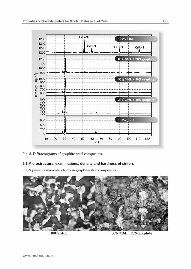
Fig. 8. presents the diffractograms of graphite-steel composites. As results from X-ray examinations, the sinter 316L exhibits austenitic structure (CrFeNi phase). Steel sinters modified with graphite revealed the presence of hexagonal graphite and rhombohedral graphite (unstable thermally), made of deformed hexagonal graphite [55].
www.intechopen.com
Properties of Graphite Sinters for Bipolar Plates in Fuel Cells
199
Fig. 8. Diffractograms of graphite-steel composites.
5.2 Microstructural examinations, density and hardness of sinters
Fig. 9 presents microstructures in graphite-steel composites.
100% 316L 80% 316L + 20% graphite
www.intechopen.com

Corrosion Resistance
200
50% 316L + 50% graphite 20% 316L + 80% graphite
100% graphite
Fig. 9. Microstructures of graphite-steel composites, magnitude 100 x.
Table 4 contains the values of density for 316L steel sinter and graphite-steel composites. Addition of graphite to the material reduces density from the level of 7.16 g cm-3 for steel to the level of 2.35 g cm-3 for the sinter modified with 80% of graphite. Modification of steel sinter 316L with graphite allows for obtaining materials with reduced density. With respect to future applications of these materials for bipolar plates in fuel cells, the use of light materials will allow for achievement of one of the most essential goals of hydrogen technologies, i.e. reduction in generator weight. Addition of graphite to steel sinter impacts also on material hardness. Change in sinter hardness with concentration of graphite in the composite is presented in Table 4.
Composites Densisty of sinter [g cm-3] Hardness 100% 316L 7.16 ± 0.38 79 ± 3.75 HRB 80% 316L + 20% grafit 6.93 ± 0.34 45 ± 4.15 HRB 50% 316L + 50% grafit 3.81 ± 0.19 35 ± 1.75 HRB 20% 316L + 80% grafit 2.35 ± 0.11 86 ± 4.30 HRF 100% grafit 1.97 ± 0.09 97 ± 4.85 HRF
Table 4. Density and hardness of graphite-steel composites.
www.intechopen.com

Properties of Graphite Sinters for Bipolar Plates in Fuel Cells
201
5.3 Stereology of composite grain size
Table 5 contains mean cross-sectional surface area, mean number of grains per mm2 of the surface and mean number of grains per mm3 of graphite-steel composites. Based on the data contained in the table, one should note that no effect of chemical composition of the sinter on mean grain size is observed. Mean grain diameter varies from 48 to 68 mm, whereas the greatest grain diameters are observed for the sinter with 50% proportion of graphite. The data are also presented in Fig. 10.
Composites Mean grains
diameter [mm]
Mean surfach of grains
[mm2]
Mean number of grains per
1mm2
Mean number of grains per
1mm3
100% 316L 0.055 0.00346 227 3 633 80% 316L + 20% grafit 0.048 0.00195 512 11 585 50% 316L + 50% grafit 0.068 0.00427 280 4 492 20% 316L + 80% grafit 0.055 0.00346 227 3 633 100% grafit 0.051 0.01275 210 3 369
Table 5. Mean values of grain parameters in graphite-steel composites.
Fig. 10. Relationship between mean grain diameter in graphite-steel composite and proportion of graphite in the composite.
www.intechopen.com

Corrosion Resistance
202
5.4 Composite porosity
A variety of materials and methods of modification of the surface of materials used for bipolar plates points to rising interest in fuel cell technologies, with particular focus on the design of the cell. Main requirements concerning commercial use of materials for manufacturing fuel cells is the relationship between high corrosion resistance and low contact resistance, with low costs of manufacturing. Corrosion rate, contact resistance and wettability of material depend to some degree on material porosity. Therefore, the investigations of functional properties were started from the analysis of pore composition in the sinters included in the study.
Assessment of porosity concerned graphite-steel composites. 316L steel sinters with addition of graphite exhibit varied porosity depending on the proportion of graphite. Fig. 11a presents hysteresis for intrusion and extrusion pressure for mercury in 316L sinter. Narrow pressure hysteresis loop points to the presence of flat pores in the material. Similar profile of hysteresis for mercury intrusion and extrusion pressure was found for other composites included in the study. Fig. 11.b. presents distribution of pore diameters in the sinters included in the study. It should be emphasized that graphite-steel composites show pores with diameters which correspond to mesopores. Only in the sinter with 50% proportion of graphite no pores from the range of diameters corresponding to mesopores were found, whereas macropores with diameters over 0.08 ┤m were observed.
Fig. 11. Hysteresis of mercury intrusion/extrusion in graphite sinters and distribution of pores depending on the proportion of stainless steel in the sinter.
Table 6 presents the values of porosities evaluated based on microstructural examinations and tests using mercury porosimeter. The lowest porosity among the composites studied was found for 316L steel sinter (9.59%). Addition of graphite with the amount of 20% considerably enhances porosity of material compared to steel sinter. Other sinters, enriched with 50% and 80% of graphite, exhibit lower porosity compared to the sinter of 80% of 316L + 20% of graphite, but this is still the value higher than the value of porosity estimated for 316L sinter.
www.intechopen.com

Properties of Graphite Sinters for Bipolar Plates in Fuel Cells
203
Rodzaj kompozytu Porosity [%]
100% 316L 9.59
80% 316L + 20% grafit 14.43
50% 316L + 50% grafit 12.17
20% 316L + 80% grafit 11.09
100% grafit 10.73
Table 6. Comparison of porosity in graphite-steel composites.
5.5 Investigations of sinter wettability
In consideration of the degree of wettability, the materials are typically divided into lyophilic materials, which have strong affinity for water (these materials attract water particles) (Fig. 12a) and the materials which repel water particles, termed lyophobic (Fig. 12b). Contact angle Θ provides a measure of wettability, which is an angle between the surface of a solid and tangent going through the point of contact of solid, liquid or gaseous phase determined for the liquid phase. It is conventionally adopted that solid bodies which are characterized by contact angles of Θ < 90° are wettable; these materials show high surface energy (if the liquid is water, these materials are termed hydrophilic). Materials which exhibit contact angle of Θ > 90° are regarded to be non-wettable (lyophobic or, alternatively, hydrophobic = low surface energy).
Fig. 12. Diagram of wetting hydrophobic and hydrophilic materials.
In order to determine the effect of chemical composition of a composite on surface wettability, the analysis of wettability was carried out through evaluation of the value of Θ angle. The investigations concerned 316L steel sinter and sinters with addition of graphite. Fig. 13 presents contact angles evaluated for composite materials. A linear relationship between the proportion of graphite and surface wettability: contact angle increases with proportion of graphite in the composite. The highest contact angle was found for the sinter
www.intechopen.com

Corrosion Resistance
204
of 100% graphite (102o). Addition of graphite to steel affects surface energy of the material: hence, composites which contain 50% and more of graphite are numbered among a group of materials which are not hydrophobically wettable. The value of Θ angle evaluated for the materials used in the study are contained in the Table 7.
Fig. 13. Contact angle evaluated for graphite-steel composites.
Composites Contact angle Θ [o]
100% 316L 75 ± 0.15
80% 316L + 20% grafit 83 ± 0.23
50% 316L + 50% grafit 94 ± 0.28
20% 316L + 80% 434L 97 ± 0.32
100% grafit 102 ± 0.37
Table 7. Values of contact angles for graphite-steel composites.
The authors of the study [56] demonstrated that material porosity affects contact angle. Fig. 14 presents the relationship between contact angle and sinter porosity. As can be observed, the relationship of both parameters which characterize the surface is non-linear. The materials whose porosity varies from 10 to 12% are numbered among hydrophobic materials. In the case of graphite-steel composites, with porosity higher than 12%, contact angle is lower than 90o.
5.6 Sinter roughness measurements
The available literature reports that contact resistance and wettability depend on surface geometry [57-58]. If a material is hydrophobic, a drop covers roughness in the surface and smoothens the unevenness (homogeneously) or it only touches the roughness, leaving a space between the drop and the solid (heterogeneously) (see Fig. 15).
www.intechopen.com

Properties of Graphite Sinters for Bipolar Plates in Fuel Cells
205
Fig. 14. Effect of porosity on contact angle in graphite-steel composites.
Fig. 15. Behavior of a drop on hydrophobic material depending on surface geometry: (a) homogeneous, (b) heterogeneous.
Table 8 contains the values of height and longitudinal parameters for 316L sintered steel and graphite-steel composites. The substantial impact on surface geometry in sinters is from the presence of graphite. In the case of rough surface, an insignificant contribution of contact surface is observed. It is essential for fuel cells that the surface of the material for these parts is smooth, which is obtained through polishing or covering the surface with a coating [59]. Graphite, as a material with high porosity is subjected to polishing in order to obtain the smooth surface.
www.intechopen.com

Corrosion Resistance
206
As results from the data contained in Table 8, addition of 20% of graphite to the composite considerably increases surface roughness. Further addition of graphite to the steel insignificantly reduces roughness, but it is still higher than roughness in 100% steel sinter 316L. This fact should be closely associated with the porosity revealed for individual composites.
Composites Parameters of surfach geometry Height feature of profile Lengthwise feature of profile Ra [┤m] Rz [┤m] Sm [mm] Dp [%]
100% 316L 4.67 55.7 0.06 25.5 80% 316L + 20% grafit 7.12 76.5 0.06 32.4 50% 316L + 50% grafit 6.67 70.9 0.06 28.6 20% 316L + 80% grafit 6.04 65.4 0.06 24.1 100% grafit 5.46 52.3 0.05 23.6
Table 8. Parameters of surface geometry in graphite-steel composites.
5.7 Measurements of contact resistance in composites
In order to determine the effect of composition of a composite on contact resistance of interfacial contact, the measurements of contact resistance between graphite-steel composites and the diffusion layer were carried out (Fig. 7). An increase in stress value causes the decrease in contact resistance, whereas at high values of pressure force, contact resistance does not change. The values of contact resistance are the lowest for the system of 316L steel sinter – diffusion layer (Fig. 16). Addition of graphite to steel sinter elevates contact resistance by nearly 40 mΩ cm2 in the case of a composite 80% 316L + 20% graphite.
Fig. 16. Surface contact resistance for graphite-steel composites depending on stress.
www.intechopen.com

Properties of Graphite Sinters for Bipolar Plates in Fuel Cells
207
5.8 Assessment of corrosion resistance in sinters
With regard to application of the used materials, one should determine corrosion resistance in the sinters. Fig. 17 presents the patterns of potentiokinetic curves recorded under conditions of work of fuel cell. The sinter 100% 316L is subjected to passivation both under conditions of cathode operation and under conditions of anode operation. Corrosion potential of the sinter 100% 316L in the analyzed environment does not change whether the solution was saturated with oxygen or hydrogen and amounts to –0.30 V vs. NEK. In the case of composite graphite-steel materials, addition of graphite caused an increase in corrosion resistance of the sinter. As results from the profile of the potentiokinetic curves, value of current density in the anode range is decreased even by two orders of magnitude. The value of corrosion potential in 316L+graphite sinters is insignificantly changed or remains at the same level compared to Ekor for the sinter of 100% 316L. It should be noted that the value of corrosion potential for the sinter of 100% graphite is shifted towards positive values and amounts to ca. 0.09 V vs. NEK in the solution saturated with O2, and ca. -0.02 V vs. NEK in the solution saturated with H2.
Fig. 17. Potentiokinetic curves recorded for graphite-steel composites.
Values of corrosion parameters estimated based on potentiokinetic curves are contained in Tab. 9.
Parameters 100% 316L
80% 316L + 20% graphite
50% 316L + 50% graphite
20% 316L + 80% graphite
100% graphite
O2
envi
ronm
ent Ekor [V] -0.336 -0.374 -0.390 -0.379 0.098
ikor [A cm-2] 90.7 · 10-4 22 · 10-4 13 · 10-4 8.00 · 10-4 5.53 · 10-4
i przy 0.6V [A cm-2]
2.263 0.128 0.040 0.017 0.005
Rp [Ω cm2] 30.56 15 784.4 25 615.6 61 244.2 102 404.4
H2
envi
ronm
ent Ekor [V] -0.303 -0.357 -0.406 -0.314 -0.026
ikor [A cm-2] 58.0 · 10-4 9.42 · 10-5 7.76 · 10-5 6.12 · 10-5 9.42 · 10-5
i przy -0.1V [A cm-2]
0.008 0.004 0.030 0.002 1.26
Rp [Ω cm2] 687.16 285 641.3 450 340.7 533 957.2 638 985.3
Table 9. Corrosion parameters of graphite – stainless steel composites.
www.intechopen.com

Corrosion Resistance
208
Fig. 18 presents the effect of addition of graphite to sintered steel on polarization resistance for the material in the corrosion environment used in the study. The highest corrosion resistance was found for the sinter of 100% graphite, whereas sinter of 100% of 316L steel, compared to graphite, exhibit nearly 1000 time lower polarization resistance in the environment of H2 and several thousand times lower in the environment of O2. The sinters are characterized by higher corrosion resistance in the solution saturated with hydrogen (including the sinter of 100% 316L), compared to the O2 solution.
Fig. 18. Change in polarization resistance depending on proportion of graphite in a composite.
6. Conclusions
The main task of bipolar plates in fuel cells is to ensure even distribution of reactants on electrode surface. In order to meet this requirement, solid materials are cut the channels with a variety of shapes. In the case of use of porous material, obtained by means of powder metallurgy, surface unevenness forms the channels which supply and discharge media. From the standpoint of economics, the intended porosity of material is beneficial. With consideration of seeking new solutions and opportunities in the field of material choice in order to facilitate and optimize operation of machines, it seems entirely legitimate to investigate the problems analyzed in the present study.
Based on the investigations, the following conclusions were drawn:
- through modification of stainless steel with addition of graphite, it is possible to obtain materials with desired density (according to DOE requirements), porosity, mechanical strength and corrosion resistance;
www.intechopen.com

Properties of Graphite Sinters for Bipolar Plates in Fuel Cells
209
- percentage of individual components in the proposed material impacts on stereological parameters of composites;
- depending on the ratio of graphite to steel in a composites, the materials with different porosity can be obtained; addition of 20% of graphite significantly elevates composite porosity;
- addition of graphite to steel affects surface energy in the material, and, consequently, the composites with 50% and more of graphite are numbered among a group of non-wettable (hydrophobic) materials;
- proportion of individual components in the sinter affects the height and longitudinal parameters of surface geometry in composites;
- porosity in the composites included in the study, values of surface geometry and grain diameter affect contact resistance between the composites (bipolar plate in fuel cell) and diffusion layer; the lowest value of interfacial resistance was found for 100% 316L material which exhibits the lowest porosity and the lowest values which characterize surface geometry (the smoothest);
- the highest corrosion resistance among the materials included in the study is observed for 100% graphite; in the case of composite graphite-steel materials, addition of graphite caused elevated corrosion resistance in the sinter; addition of 20% of graphite increased the value of polarization resistance (Rp) by several hundred times: from 30.56 Ω cm2 to 15 784,4 Ω cm2 in O2 environment.
7. References
[1] Jayakumar K., Pandiyan S., Rajalakshmi N., Dhathathreyan K.S., Cost-benefit analysis of commercial bipolar plates for PEMFC’s, J. Power Sources, 161 (2006) 454-459.
[2] U.S. Department of Energy (DOE) www.energy.gov [3] Hermann A., Chaudhuri T., Spagnol P., Bipolar plates for PEM fuel cells: A review, Int. J.
Hydrogen Energy, 30 (2005) 1297-1302. [4] Mehta C., Cooper J.S., 2003, Review and analysis of PEM fuel cell design and
manufacturing, J. Power Sources, 114 (2003) 32-53. [5] Lee S.-J., Huang C.-H., Lai J.-J., Chen Y.-P., Corrosion- resistance component for PEM
fuel cells, J. Power Sources, 131 (2004) 162-168. [6] Antepara I., Villarreal I., Rodríguez-Martínez L.M., Lecada N., Castro U., Leresgoiti A.,
Evaluation of ferritic steels for use as interconnects and porous metal supports in IT-SOFCs, J. Power Sources, 151 (2005) 103-107.
[7] Lee S.-J., Lai J.-J., Huang C.-H., 2005, Stainless steel bipolar plates, J. Power Sources, 145 (2005) 362-368.
[8] Kumar A., Reddy R. G., Materials and design development for bipolar/end plates in fuel cells, J. Power Source, 129 (2004) 62-67.
[9] Mathur R.B., Dhakate S.R., Gupta D.K., Dhami T.L., Aggarwal R.K., Effect of different carbon fillers on the properties of graphite composite bipolar plate, J. Mat. Proc. Tech., 203 (2008) 184-192.
[10] Dhakate S.R., Sharma S., Borah M., Mathur R.B., Dhami T.L., Expanded graphite-based electrically conductive composites as bipolar plate for PEM fuel cell, Int. J. Hydrogen Energy, 33 (2008) 7146-7152.
[11] Yasuda E., Enami T., Hoteida N., Lanticse-Diaz L.J., Tanabe Y., Akatsu T., Carbon alloys- multi-functionalization, Materials Sci. Engineering B, 148 (2008) 7-12.
www.intechopen.com

Corrosion Resistance
210
[12] Chung C.-Y., Chen S.-K., Chiu P.-J., Chang M.-H., Hung T.-T., Ko T.-H., Carbon film-coated 304 stainless steel as PEMFC bipolar plate, J. Power Sources, 176 (2008) 276-281.
[13] Feng K., Cai X., Sun H., Li Z., Chu P.K., Carbon coated stainless steel bipolar plates in polymer electrolyte membrane, Diamond & Related Materials, 19 (2010), 1354-1361.
[14] Fu Y., Lin G., Hou M., Wu B., Shao Z., Yi B., Carbon-based films coated 316L stainless steel as bipolar plate for proton exchange membrane fuel cells, Int. J. Hydrogen Energy, 34 (2009) 405-409.
[15] Andre J., Antoni L., Petit J.-P., Corrosion resistance of stainless steel bipolar plates in a PEMFC environment: A comprehensive study, Int. J. Hydrogen Energy, 35 (2010) 3684-3697.
[16] Kraytsberg A. Auinat M., Ein-Eli Y., Reduced contact resistance of PEM fuel cell’s bipolar plates via surface texturing, J. Powers Sources, 164 (2007) 697-703.
[17] Kim J.S., Peelen W.H.A., Hemmes K., Makkus R.C., Effect of alloying elements on the contact resistance and passivation behavior of stainless steel, Corr. Sci., 44 (2002) 635-655.
[18] Hodgson D.R., May B., Adcock P.L., Davies D.P., New lightweight bipolar plate system for polymer electrolyte membrane fuel cells, J. Powers Sources, 96 (2001) 233-235.
[19] Li M.C., Zeng C.L., Luo S.Z., Shen J.N., Lin H.C., Cao C.N., Electrochemical corrosion characteristics of type 316 stainless steel in simulated anode environment for PEMFC, Electrochim. Acta, 48 (2003) 1735-1741.
[20] Geng S., Li Y., Ma Z., Wang L., Wang F., Evaluatioof electrodeposited Fe-Ni Allom on ferritic stainless steel solid oxide fuel Ce;; InterConnect, Journal of Power Sources, 195 (2010) 3256-3260.
[21] Paulauskas I.E., Brady M.P., Meyer III H.M., Buchanan R.A., Walker L.R., Corrosion behavior of CrN, Cr2N and π phase surfaces on nitrided Ni-50Cr for proton exchange membrane fuel cell bipolar plates, Corr. Sci., 48 (2006) 3157-3171.
[22] El-Enim S.A.A., Abdel-Salam O.E., El-Abd H., Amin A.M., New electroplated aluminum bipolar plate for PEM fuel cell, J. Power Sources, 177 (2008) 131-136.
[23] Nikam V.V., Reddy R.G., Corrosion studies of a copper-berylium alloy in a simulated polymer electrolyte membrane fuel cell environment, J. Power Sources, 152 (2005) 146
[24] Nikam V.V., Reddy R.G., Copper alloy bipolar plates for polymer electrolyte membrane fuel cell, Electrochim. Acta, 51 (2006) 6338-6345.
[25] Heinzel A., Mahlendorf F., Niemzig O., Kreuz C., Injection moulded low cost bipolar plates for PEM fuel cells, J. Power Sources, 131 (2004) 35-40.
[26] Radhakrishnan S., Ramanujam B.T.S., Adhikari A., Sivaram S., High-temperature, polymer hybrid composites for bipolar plates: Effect of processing conditions on electrical properties, J. Power Sources, 163 (2007) 702-707.
[27] Makkus R.C., Janssen A.H.H., F. A. de Bruijn, R. K. A. M. Mallant, Stainless steel for cost-competitive bipolar plates in PEMFCs, Fuel Cells Bulletin, 17 (2000) 5-9.
[28] Wang S.-H., Peng J., Lui W.-B., Surface modification and development of titanium bipolar plates for PEM fuel cells, J. Power Sources, 160 (2006) 485-489.
[29] Mennola T., Design and experimental characterization of polymer electrolyte membrane fuel cells, Thesis, Helsinki University of Technology, Espoo, 2000.
www.intechopen.com

Properties of Graphite Sinters for Bipolar Plates in Fuel Cells
211
[30] Dudek A., Włodarczyk R., Nitkiewicz Z., Structural analysis of sintered materials used for low-temperature fuel cell plates, Materials Science Forum, 638-642 (2010) 536-541.
[31] Wlodarczyk R., Dudek A., Sintering stainless steel as bipolar plate material for polymer electrolyte membrane fuel cell, Steel Research, 81 (2010) 1288-1291.
[32] Wlodarczyk R., Dudek A., Properties and application of sintered stainless steel as interconnectors in fuel cell, Solid State Phenomena, 165 (2010) 231-236.
[33] Dudek A., Wlodarczyk R., Fuel cells as unconventional energy sources, Materials Engineering 2010, Collective monograph; Material and exploitation problems in modern Material Engineering, Monography 6 (2010) 194-204.
[34] Wlodarczyk R., Dudek A., Nitkiewicz Z., Application of austenite sinters as parts in hydrogen fuel cell, Engineering and quality production, Monography, Dnipropetrovsk 2010, 134-149.
[35] Wlodarczyk R., Effect of pH on corrosion of sintered stainless steel used for bipolar plates in polymer exchange membrane fuel cells, 6th International Conference Mechatronic System and Materials, Opole 2010, 219-220.
[36] PN-EN ISO 643, Stal. Mikrograficzne okre]lanie wielko]ci ziarna. [37] PN-74/M-04255 Struktura geometryczna powierzchni- Falisto]ć powierzchni-
Okre]lenia podstawowe i parametry. [38] PN-87/M-04251 Struktura geometryczna powierzchni- Chropowato]ć powierzchni-
Warto]ci liczbowe parametrów. [39] Davies D.P., Adcock P.L., Turpin M., Rowen S.J., Stainless steel as bipolar plate material
for solid polymer fuel cells, Journal of Power Sources, 86 (2000) 237-242. [40] Davies D.P., Adcock P.L., Turpin M., Rowen S.J., Stainless steel as bipolar plate material
for solid polymer fuel cells, Journal of Power Sources, 86 (2000) 237-242. [41] Zhang L., Liu Y., Song H., Wang S., Zhou Y., Hu S.J., Estimation of contact resistance in
proton exchange membrane fuel cells, Journal of Power Sources, 162 (2006) 1165-1171.
[42] Barber M., Sun T.S., Petrach E., Wang X., Zou Q., Contact mechanics approach to determine contact surface area between bipolar plates and current collector in proton exchange membrane fuel cells, Journal of Power Sources, 185 (2008) 1252-1256.
[43] Cheng X., Shi Z., Glass N., Zhang L., Zhang J., Song D., Liu Z.-S., Wang H., Shen J., A review of PEM hydrogen fuel cell contamination: Impacts, mechanisms, and mitigation, J. Power Sources, 165 (2007) 739-756.
[44] Shi M., Anson F.C., Dehydration of protonated Nafion® coatings induced by cation exchange and monitored by quartz crystal microgravimetry, J. Electroanal. Chem., 425 (1997) 117-123.
[45] Inaba M., Kinumoto T., Kiriake M., Umebayashi R., Tasaka A. Ogumi Z., Gas crossover and membrane degradation in polymer electrolyte fuel cells, Electrochimica Acta, 51 (2006) 5746-5753.
[46] André J., Antoni L., Petit J.-P., De Vito E., Montani A., Electrical contact resistance between stainless steel bipolar plate and carbon felt in PEMFC: A comprehensive study, International Journal of Hydrogen Energy, 34 (2009) 3125-3133.
[47] Gülzow E., Schulze M., Gerke U., Bipolar concept for alkaline fuel cells, Journal of Power Sources, 156 (2006) 1-7.
www.intechopen.com

Corrosion Resistance
212
[48] Gamboa S.A., Gonzalez-Rodriguez J.G., Valenzuela E., Campillo B., Sebastian P.J., Reyes-Rojas A., Evaluation of the corrosion resistance of Ni-Co-B coatings in simulated PEMFC environment, Electrochimica Acta, 51 (2006) 4045-4051.
[49] Shores D.A., Deluga G.A., Handbook of fuel cells – fundamentals, technology and applications, New York; Wiley; (2003) 273.
[50] Lee Y.-B., Lee C.-H., Lim D.-S., The electrical and corrosion properties of carbon nanotube coated 304 stainless steel/polymer composite as PEM fuel cell bipolar plates, International Journal of Hydrogen Energy, 34 (2009) 9781-9787.
[51] Borup R.L., Vanderburgh N.E., Design and testing criteria for bipolar plate materials for PEM fuel cell applications, Proces. Mat., Res., Soc., Symp., 393 (1995) 151.
[52] Fleury E., Jayaraj J., Kim Y.C., Seok H.K., Kim K.Y., Kim K.B., Fe-based amorphous alloy as bipolar plates for PEM fuel cell, Journal of Power Sources, 159 (2006) 34-37.
[53] Amin M. A., Ibrahim M.M., Corrosion and corrosion control of mild steel in concentrated H2SO4 solutions by a newly synthesized glycine derivative, Corrosion Science, 53 (2011) 873-885.
[54] Bala H., Korozja materiałów – teoria i praktyka, Wydawnictwo Wydziału Inżynierii Procesowej, Materiałowej i Fizyki Stosowanej, Częstochowa, 2002.
[55] Parthasarathy G., Sreedhar B., Chetty T.R.K., Spectroscopic and X-ray diffraction studiem on fluid deposited rhombohedral graphite from the Eastern Ghats Mobile Belt, India, Current Science, 90 (2006) 995-1000.
[56] Tang Y., Yuan W., Pan M., Wan Z., Feasibility study of porous copper fiber sintered felt: A novel porous flow field in proton exchange membrane fuel cell, Int. J. Hydrogen Energy, 35 (2010) 9661-9677.
[57] Kim D.-K., Lee D.-G., Lee S., Correlation of microstructure and surface roughness of disc drums fabricated by hot forging of an AISI 430F stainless steel, Metallurgical and Materials Transactions 32A, (2001) 1111-1116.
[58] Hakiki N.E., Structural and photoelectrochemical characterization of oxide films formed on AISI 304 stainless steel, Journal of Applied Electrochemistry, 40 (2010) 357-364.
[59] Mahabunphachai S., Cora Ö. N., Koç M., Effect of manufacturing processes on formability and surface topography of proton exchange membrane fuel cell metallic bipolar plates, Journal of Power Sources, 195 (2010) 5269-5277.
www.intechopen.com

Corrosion ResistanceEdited by Dr Shih
ISBN 978-953-51-0467-4Hard cover, 472 pagesPublisher InTechPublished online 30, March, 2012Published in print edition March, 2012
InTech EuropeUniversity Campus STeP Ri Slavka Krautzeka 83/A 51000 Rijeka, Croatia Phone: +385 (51) 770 447 Fax: +385 (51) 686 166www.intechopen.com
InTech ChinaUnit 405, Office Block, Hotel Equatorial Shanghai No.65, Yan An Road (West), Shanghai, 200040, China
Phone: +86-21-62489820 Fax: +86-21-62489821
The book has covered the state-of-the-art technologies, development, and research progress of corrosionstudies in a wide range of research and application fields. The authors have contributed their chapters oncorrosion characterization and corrosion resistance. The applications of corrosion resistance materials will alsobring great values to reader's work at different fields. In addition to traditional corrosion study, the book alsocontains chapters dealing with energy, fuel cell, daily life materials, corrosion study in green materials, and insemiconductor industry.
How to referenceIn order to correctly reference this scholarly work, feel free to copy and paste the following:
Renata Wlodarczyk, Agata Dudek, Rafal Kobylecki and Zbigniew Bis (2012). Properties of Graphite Sinters forBipolar Plates in Fuel Cells, Corrosion Resistance, Dr Shih (Ed.), ISBN: 978-953-51-0467-4, InTech, Availablefrom: http://www.intechopen.com/books/corrosion-resistance/corrosion-resistance-of-composites-based-to-graphite-used-as-bipolar-plates-in-fuel-cells