insulation
DESCRIPTION
Thermal InsulationTRANSCRIPT

INSULATION

Thermal insulator :-
• Poor conductor of heat • Low thermal conductivity
Materials are porous, containing large number of dormant air cells.

Purpose of Insulation Used to prevent heat loss or heat gain in
manufacturing processes and buildings To provides more accurate control of
process temperatures To give protection of personnel It Prevents condensation on cold surfaces
and the resulting corrosion.
Benefits:
Reduces over-all energy consumption

Types and Application
• Low Temperature Insulations (up to 90oC)Used for refrigerators, cold and hot water systems, storage tanks, etc. (Cork, Wood, 85% magnesia, Mineral Fibers, Polyurethane etc)
• Medium Temperature Insulations (90 – 325oC) Used in low temperature, heating and steam raising equipment, steam lines,
flue ducts etc. (include 85% Magnesia, Asbestos, Calcium Silicate and Mineral Fibers etc. )
• High Temperature Insulations (325o C – above ) Used for super heated steam system, oven dryer and furnaces etc.
(Asbestos, Calcium Silicate, Mineral Fibre, Mica and, Fireclay or Silica based insulation and Ceramic Fibre. )

Economic Thickness of Insulation (ETI)
• The effectiveness of insulation follows the law of decreasing returns. Hence, there is a definite economic limit to the amount of insulation
• An increased thickness is uneconomical and cannot be recovered
• This limiting value is termed as economic thickness of insulation.
Cost
M
I
H
I + H
Insulation Thickness
Figure 5.2 Determination of economic thickness of insulation
I: Cost of Insulation H : Cost of Heat LossI + H : Total Cost M : Economic Thickness

O p t i m a l I n s u l a t i o n
5 0 m m i n s u l a t i o n c o m p a r e d w i t h a n u n i n s u l a t e d p i p e : 2 7 5 - 2 5 = 2 5 0 K c a l / m
2 6 0 l i t r e o i l p e r y e a r
5 0 m m i n s u l a t i o n c o m p a r e d w i t h 1 0 0 m m i n s u l a t i o n : 2 5 - 1 5 = 1 0 K c a l / m
9 l i t r e o i l p e r y e a r
H e a t l o s s , 8 9 m m b l a c k s t e e l p i p e , 9 0 o C
U n i n s u l a t e d2 7 5 K c a l / m
1 0 0 m m i n s u l a t i o n1 5 K c a l / m
5 0 m m i n s u l a t i o n2 5 K c a l / m

Quantitative upgradation
Thickness of Insulation mm
Heat Loss
Kcal/m2.hr
25 435
30 360
40 260
50 200
75 125
100 85For pipe dia 80mm,OD-88.9,Operating temp-350oC,Ambient temp-30oC
Simplest way to reduce the energy loss is to increase the thickness ofinsulation quantitatively.But it has limitations of space and restrictions.Hence quantitative upgradation may not be optimum solution

Qualitative Upgradation
• Qualititative Upgradation involves use of material with superior thermal conductivity, scientifically determined optimum economic thickness and good method of application
• Use of machine felted and machine compressed mattress
• Use of modern practice of concentric pipe section

Hot Insulation
Diff. in Temp. between Ambient & Surface. Deg C
Heat Loss in
K.Cals/Sq.m/Hr
50 500
100 1350
200 3800
400 13650Ambient 35oC, Emissivity-0.8 , wind velocity –0 m/sec
•Table gives the extent of energy loss from hot surface to ambient under normal operating conditions• Good insulation can reduce the heat losses to 75 Kcals/sq.m/hr
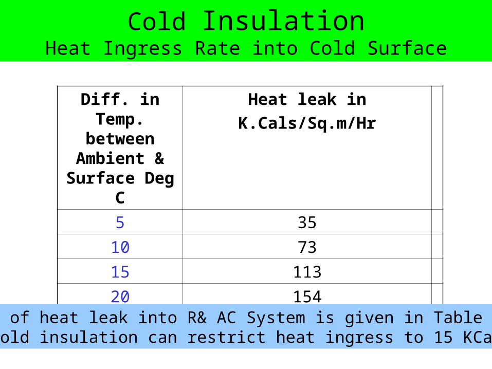
Cold InsulationHeat Ingress Rate into Cold Surface
Diff. in Temp. between
Ambient & Surface Deg C
Heat leak in
K.Cals/Sq.m/Hr
5 35
10 73
15 113
20 154Ambient 35oC, Emissivity-0.9 , wind velocity –0 m/sec
• The rate of heat leak into R& AC System is given in Table• Proper cold insulation can restrict heat ingress to 15 KCals/sq.m/hr

Surface temp without insulation–170oC
Ambient temperature – 25oC
• Existing Heat Loss S = [10+ (Ts-Ta)/20] x (Ts-Ta)
Ts = 170oC
Ta = 25oC
S = [10+(170-25)/20] x (170-25) = 2500 Kcal/hr-m2
Ts – 65oC
Ta – 25oC
• Modified System
S = [10+(65-25)/20] x (65-20)
= 480 K.cal/hrM2
Example:Surface heat loss Before and after insulationVarious charts, graphs are available for heat loss computation.This equation can be used up to 2000C surface temperature. Factors like wind velocities, conductivity of insulating material etc has not been considered in the equation
S = [10+(Ts-Ta)/20] x (Ts-Ta)
Where S = Surface heat loss in Kcal/hr m2
Ts= Hot surface temperature in oC, Ta= Ambient temperature in oC
Total heat loss/hr (Hs)= S x A Where A is the surface area in m2

Ceramic Fibre Application• Ceramic fibre is an alumino silicate material • Produced in bulk wool form and needled into blanket
mass of various densities ranging from 64 to 190 kg/m3

Features and Merits of Ceramic Fibre
Merits1. Offers thin walled and light weight furnace design and used as Primary
refractory lining material2. Quick Installation by layered/modular and replaces conventional dence
refractory brick and monolithic products3. Energy Savings (10 – 50%)4. Increased furnace Productivity5. Batch time reduction6. Low maintenance cost7. Extended life service
Demerits1. Normally Suitable upto 1250oc2. Cannot withstand abrasive &impact loading 3. High velocity gas can damage the fibre

Emissivity of refractory materials at different temperatures
For intermittent furnaces or where rapid heating is required, use of such coatings was found to reduce fuel or power to tune of 25-45%. Other benefits are temperature uniformity and increased refractory life
Furnaces, which operate at high temperature, have emissivities of 0.3. By using coatings this can go upto 0.8 thus effectively increasing the radiative heat
transfer.