instruments and methods - international glaciological … · journal of glaciolog)', vol. 27,...
TRANSCRIPT
Journal of Glaciolog)', Vol. 27, No. 97. 1981
INSTRUMENTS AND METHODS
SYSTEMS FOR MEASURING THICKNESS OF TEMPERATE AND POLAR ICE FROM THE GROUND OR FROM THE AIR
By RAYMOND D. WATTS and DAVID L. WRIGHT
(U.S. Geological Survey, Denver, Colorado 80225, U.S.A.)
ABSTRACT. Equipment has been designed and tested for ground-based and airborne sounding of temperate glaciers. The transmitter is a free-running pulse generator that uses avalanche-mode transistor breakdown to create high-voltage pulses. The transmit and receive antennas are resistively loaded dipoles; for the airborne system, a twin-lead transmit element and a three-layer coaxial receive element are used on the inboard end of the respective antennas. The sounders are broad band systems; oscilloscopes are used for receivers. ' The oscilloscope trace is recorded photographically in the ground-based systems. A sampling oscilloscope is used in the airborne system-the sampling process strobes the waveform to audio frequencies so that it can be recorded on magnetic tape. Echoes have been obtained from ice depths of 550 m using the airborne system and about I 000 m using the ground-based system.
REsuME. Procedes de mesure de I'epaisseur des glaces temphees et polaires depuis le sol ou par une uoie ahienne. On a con~u et essaye un equipement pour sonder des glaciers temperes depuis un aeronef ou depuis une base au sol. L'emetteur est un generateur libre d'impulsions qui utilise des decharges en forme d'avalanche par transistor pour creer des impulsions a fort voltage. Les antennas emettrices et receptrices sont des dipoles charges en resistance. Pour la version aerienne, un element emetteur a direction jumelee et un recepteur coaxial a trois niveaux sont utilises sur l'extremite du bord des antennes respectives. Les sondeurs sont des systemes a large bande; on utilise des oscilloscopes comme recepteurs. Le signal de l'oscilloscope est enregistre photographiquement dans les apparei ls bases au sol. Dans la version aerienne, on utilise un oscilloscope a echantillonnage. La procede par echantillonnage transforme les oscillations en frequences acoustiques de sorte qu'on peut les enregistrer sur ban des magnetiques. Des echos ont ete obtenus depuis des profondeurs de glace de 550 m avec la version aerienne et d'environ I 000 m avec la version terrestre.
ZUSAMMENFASSUNG. Systeme zur Messllng der Dicke temperierten und polaren Eises am Boden oder aus der Luft. Zur Dickenmessung temperierten Eises von der Oberflache und aus der Luft wurden neue Geriite entwickelt und erprobt. Der Sender ist ein Impulsgenerator, der zur Erzeugung hochgespannter Impulse eine lawinenartige Transistor-Ausliisung benutzt. Die Sende- und Empfangsantennen sind aufgeladene Widerstandsdipole. Fur das flugzcuggetragene Systeme sind ein Scndeelement mit Doppelleiter und ein dreiadriges, koaxiales Empfangselement vorgesehen, die am inneren Ende der jeweiligen Antennen sitzen. Die Messung erfolgt mit Breitbandsystemen; an die Empfangcr sind Oszilloskope angeschlossen. Die Oszilloskopaufzeichnung wird beim Bodensystem photographisch registriert. Das flugzeuggetragene System benutzt ein Auswahl-Oszilloskop, das die Wellenfront zur Aufzeichnung auf Magnetband in Audiofrequenzen umwandelt. Mit dem flugzeuggetragenen System wurden Reflexionen aus Eistiefen von 550 m erhalten, mit dem Bodensystem soIche von etwa I 000 m.
INTRODUCTION
In August and September of 1978, we successfully gathered glacier-depth data using the first-known airborne radio echo-sounder for temperate glaciers. The tests were carried out over glaciers in Alaska, and most of the work was done at Columbia Glacier. The system was carried in a "short takeoff and landing" (STOL) airplane. This airborne system was the product of an evolution of ground-based sounders. Our ground based systems have not previously been presented in the literature, so we describe them here.
Watts and England ( 1976) described design criteria for a temperate-glacier sounder; they deduced that the main impediment to detecting bottom echoes in temperate ice is the clutter from scatterers within the glacier mass, rather than any problem with signal strength or receiver sensitivity. The first implementation of these ideas was by Roger Vickers and Robert Bollen of Stanford Research Institute, working at South Cascade Glacier, Washington State, and Columbia Glacier, Alaska, in 1974 under contract to the V.S. Geological Survey. They introduced the technology of avalanche transistor transmitters and resistively loaded antennas. All the subsequent sounding systems developed at the V.S. Geological Survey have used similar transmitters and antennas, with varying degrees of modification.
459

JOURNAL OF GLAC10LOGY
We have not yet developed a ground-based system for continuous profiling. The equipment we describe here is used for spot measurements. Systems for continuous profiling on the ground have been described by Ferrari and others (1976), Sverrisson and others (1978), and by Bishop and others (1979).
THE GROUND-BASED SYSTEM
Figure I shows the elements of the ground-based sounder. It is powered entirely by 12 V batteries. We most frequently use sealed lead-acid batteries, with either liquid or gelatinized electrolyte. The system consists of two parts, the transmitter and the receiver; the receiver is the heavier part and is the greater user of power, mainly due to the use of an oscilloscope.
TRANSMITTER RECEIVER
J L l I
TRANSMIT RECEIVE ANTENNA ANTENNA
Fig. I. Block diagram of the ground-based radar system. Both the transmitting and receiving parts aTe operated entirery from 12 V batteries.
The pulse repetition frequency of the transmitter is limited by two factors: the output current limit of the high-voltage source and the thermal dissipation capability of the avalanche transistors. The source of high voltage can be batteries (which have a high current capability) or a power supply. A supply with a 750 V, 20 mA capacity will run the pulse generator at rates up to about 10000 pulses per second. The brightness of the trace on the oscilloscope is proportional to the pulse rate, so adequate power capacity can be important in a sunlit glacier environment.
The pulse generator circuit is shown in Figure 2A. The pulse repetition rate is governed by the choice of resistance through switch SI' which varies the charging rate of capacitor Cl' The current path during charging is shown in Figure 2B. When the voltage on Cl exceeds the sum of the breakdown voltages of either pair of series transistors, then all the transistors change from a resistive to a conducting state. If the discharging current from Cl is properly limited by the antenna or dummy-load impedance, then avalanching is non-destructive. The onset of the avalanche is very rapid, giving voltage rise-times of a few tens of nanoseconds. Figure 2C shows the current path during the avalanche discharge. When capacitor Cl has been discharged into the antenna, the transistors recover from their avalanche failure, stop passing current, and the recharging of Cl commences.
An advantage of using avalanche transistors rather than some other type of high-speed electronic switch, is that the transistors return to a non-conducting state after the initial discharge of capacitor Cl' The high-impedance state prevents antenna ringing-the shunting of current from the charged-up antenna back through a low-impedance path. The antenna discharges gradually through the high-impedance path of resistor R7• This type of coupling seems to give the shortest radiated pulse.

INSTRUMENTS AND METHODS
A-PULSE GENERATOR CIRCUIT
+ 750 V -------,
RI R4 R5 C2
-OUT
VALUES
RI-R
4 2Kn,2w °1 RS
R5
,RS
5K , 2W
R7 1.4K,IW
Cl O.OOII'-F °1 C
2 O.OII'-F
°1 2N4922
RS
R5 +OUT
-=- c2
B-CHARGING C- DISCHARGING
1-----..- - - OU T
f---4>--- + OU T
Fig. 2
A. Schematic diagram of the high-voltage pulse generator used in the transmitter of the ground-based system. B. Diagram of the current pathway during the charging period. C. Diagram of the current pathway during the discharging (transmitting ) period.
Figure 3 shows the design of either a transmitting or a receiving antenna. The resistive loading causes the antenna to support an outward-traveling wave of current but not an inward-traveling one. It is therefore possible to transmit a wave closely approximating a single cycle of the center frequency of the system. The frequency is controlled by the length of the antenna, a lthough it also depends somewhat on the resistive loading constant 'Y. The resistance per unit length at distance x from the feed point is
'Y R(x) = h-x (I)
where '¥ is a constant in ohms and h is the antenna half-length in meters. If 'Y is very large, the antenna will lose both transmitting and receiving efficiency. If it is too small, the antenna rings with current oscillating between the feed point and the antenna ends. Antenna ringing increases the noise echoes from scatter returns in the ice. Ringing may also degrade resolution and increase the difficulty of choosing a precise time for the return.

JOURNAL OF GLACIOLOGY
--jl m r- -j Im r- -j Im r-220n loon 67.1l 50n 40.ll 33.1l 29.1l 25n 22.1l 22n 25n 29.1l 33n 40n 50.ll 67.1l loon 220.ll
RESISTORS ARE ~ W, NEAREST 10% VALUES
R= RESISTANCE (n) =_"'_ METER h-Ixl
h=ANTENNA HALFLENGTH (= 10m)
t = RESISTIVE LOADING CONSTANT (= 200n)
Ixl=DISTANCE FROM FEEDPOINT
Fig. 3. Diagram of the transmitting or receiving antenna used in the ground-based radar system.
The receiving antenna can be attached directly to the oscilloscope. It is attached most effectively using a I : I pulse transformer at the antenna feed point. If the ice is sufficiently deep, though, it may be necessary to amplify the signals before they are fed into the oscilloscope. Most broadband amplifiers are 50 Q input and output impedance devices, while the antenna impedance is between 150 and 450 Q, depending on the value of the resistive loading constant 'Y. The impedance-matching network shown in Figure 4 prevents the receiving antenna from ringing due to an impedance mismatch at its terminals. The theoretical impedance ratio I : 16 was not realized; the ratio was I : 10 in the frequency band of interest. The final stage of the impedance network is the back-to-back diode arrangement, which clips the amplifier input at ± o.5 V. Oscillations resulting from high amplifier gains can be suppressed by a passive fi lter at the output of the amplifier (Fig. 5).
An oscilloscope with a bandwidth of IQ MHz is an adequate detector. Criteria in selection of an oscilloscope are: (I) power requirements, (2) weight, (3) sensitivity, (4) screen size, and (5) trace brightness. Trace brightness is particularly important; a fairly high accelerating
.. m"{~v p~ Uj~: ~ff !AMPLIFIER
- ~ _ SCHOTTKY-BARRIER
1:1 PULSE TRANSFORMERS
DIODES
IMPEDANCE-MATCHING TRANSFORMER VOLTAGE RAT IO 1: 4 IMPEDANCE RATIO 1:16
Fig. 4. Schematic diagram of impedance-matching network used between the ground-based receiving antenna and a 50 Q inputimpedance amplifier.
INPUT (50n)
OUTPUT (SOn)
Fig. 5. Schematic diagram of a 1-10 MHz band pass filter used in the ground·based system at either the input or the output of the amplifier.
INSTRUMENTS AND METHODS
potential is needed in order to generate a trace bright enough to be seen in a sunlit glacial environment. We normally used an oscilloscope camera and self-developing film to record the trace.
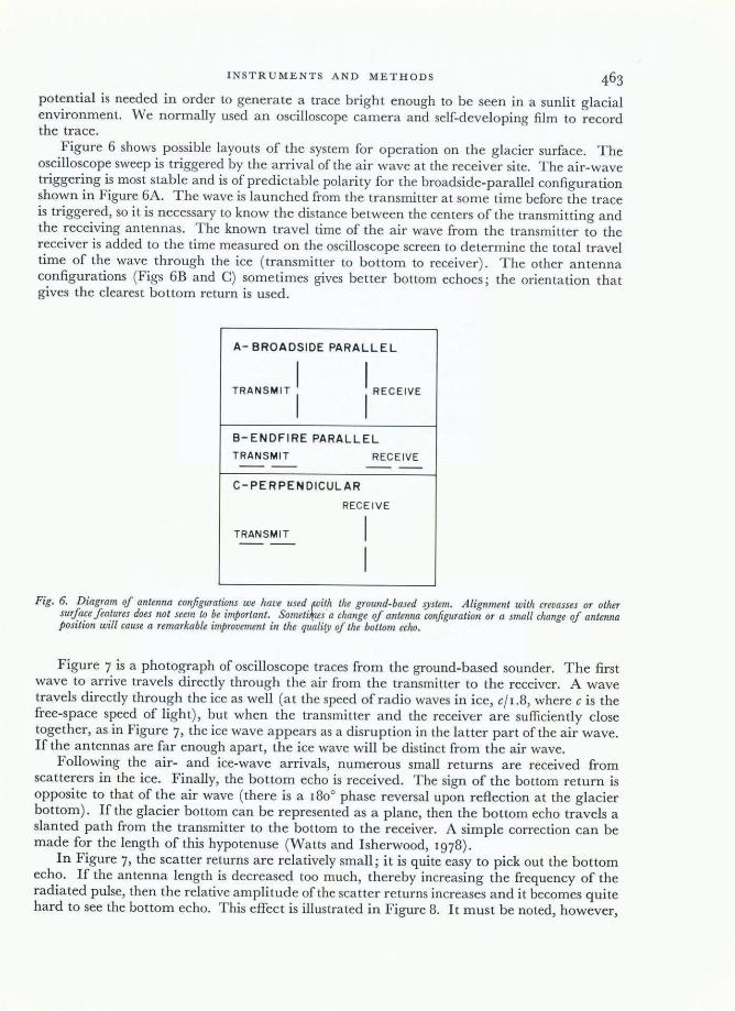
Figure 6 shows possible layouts of the system for operation on the glacier surface. The oscilloscope sweep is triggered by the arrival of the air wave at the receiver site. The air-wave triggering is most stable and is of predictable polarity [or the broadside-parallel configuration shown in Figure 6A. The wave is launched from the transmitter at some time before the trace is triggered, so it is necessary to know the distance between the centers of the transmitting and the receiving antennas. The known travel time of the air wave from the transmitter to the receiver is added to the time measured on the oscilloscope screen to determine the total travel time of the wave through the ice (transmitter to bottom to receiver). The other antenna configurations (Figs 6B and C) sometimes gives better bottom echoes; the orientation that gives the clearest bottom return is used.
A- BROADSIDE PARALLEL
TRANS. " 1 1 RECEI VE
B- ENDFIRE PARALLEL
TRANSMI T RECEIVE ---- -- --
C- PERPEND ICULAR
RECEIVE
TRANS MIT I - - --I
Fig. 6. Diagram of antenna configurations we have used (with the ground-based ijstem. Alignment with crevasses or other surface features does not seem to be important. Someti1f1es · a change of antenna configuration or a small change of antenna position will cause a remarkable improvement in the qualiry of the bottom echo.
Figure 7 is a photograph of oscilloscope traces from the ground-based sounder. The first wave to arrive travels directly through the air from the transmitter to the receiver. A wave travels directly through the ice as well (at the speed of radio waves in ice, e/1.8, where e is the free-space speed of light), but when the transmitter and the receiver are sufficiently close together, as in Figure 7, the ice wave appears as a disruption in the latter part of the air wave. If the antennas are far enough apart, the ice wave will be distinct from the air wave.
Following the air- and ice-wave arrivals, numerous small returns are received from scatterers in the ice. Finally, the bottom echo is received. The sign of the bottom return is opposite to that of the air wave (there is a 1800 phase reversal upon reflection at the glacier bottom). If the glacier bottom can be represented as a plane, then the bottom echo travels a slanted path from the transmitter to the bottom to the receiver. A simple correction can be made for the length of this hypotenuse (Watts and Isherwood, 1978).
I n F igure 7, the scatter returns are relatively small ; i t is quite easy to pick out the bottom echo. I f the antenna length is decreased too much, thereby increasing the frequency of the radiated pulse, then the relative amplitude of the scatter returns increases and it becomes quite hard to see the bottom echo. This effect is illustrated in Figure 8. It must be noted, however,

JOURNAL OF GLACIOLOGY
that longer antennas cannot guarantee a clear bottom echo where the bottom geometry is unfavorable, that is, if the bottom is too rough or if it has no facets properly oriented to reflect energy from the transmitted wave toward the receiving antenna.
The transmitting and receiving antennas can be placed quite close together, either alongside one another or end-to-end, but this may cause saturation of the amplifiers (either the pre-amplifier or the oscilloscope's internal amplifiers). Experiments need to be carried out
Fig. 7. Oscilloscope trace/rom South Cascade Glacier, Washington State. The upper and lower traces are the same except/or their vertical scale (top trace: 100 m V/division; bottom trace.' 20 m V/division ) . Horizontal sweep rate is 0.5 ps/division. Time is measllred from the positive peak 0/ the air wave (best seen in the top trace) to the first negative peak if the bottom echo-1.5 ps is the elapsed time. The transmitting and receiving antennas were 50 m apart, so 0.33 ps air-wave transit time is added. The total 1.83 ps travel time/rom the transmitter to the bottom 10 the receiver represents a path length if 306 m, or a glacier depth 0/153 m, because the radio-wave velocity in ice is about 167 m/ps.
Fig. 8. Oscilloscope trace/rom South Cascade Glacier, Washington State, at a location where scattering in the ice is particularly strong. The arrow indicates where we think the bottom echo appears. The ambiguity in a high-noise situation like this is often relieved with closely spaced observations: by following the bottom, you qften know where the echo should appear.
INSTRUMENTS AND METHODS
for each system to determine the minimum spacing that can be used. We have tried to use a single antenna for transmitting and receiving but have not yet been successful. The antenna is excited by a pulse of about a kilovolt, yet it is necessary to detect reflections of about a millivolt. The factor of 106 change in amplitudes cannot be accommodated by the resistively loaded antenna; its currents take more time to die down than the few microseconds that elapse between the transmission and the arrival of the bottom return.
Conclusions
We believe that our system is appealingly lightweight and inexpensive for ice sounding. The only way it seems possible to make a system lighter or cheaper is through reduction in weight and cost of the oscilloscope. The amplifier is essential only for deep ice (greater than 500 m), and the remaining electronic components are not expensive. Ice depths as great as I 200 m have been measured with this equipment.
THE AIRBORNE SYSTEM
To obtain glacier thickness information from large areas or where the glacier surface is heavily crevassed, it is usually not feasible to work from the glacier surface. The spectacular success of ice sounding from the air in polar regions (e.g. Robin, 1974) led us to try airborne ice sounding for temperate ice. The biggest challenge was the design of adequate antennas for the low frequencies that are used in sounding temperate ice.
A modified pulser design (Fig. 9) allowed us to use a transmitting antenna almost identical to that used in the ground-based system. The high-voltage power supply was in the airplane, and current was supplied to the pulser through two parallel wires, each having double the value of'Y that the trailing end of the antenna had (Fig. lOA). The pulser was packaged in a small cylinder of heat-conducting epoxy. The air flowing past the pulser circuit was sufficient to cool it.
The receiving antenna was a triaxial structure, as shown in Figure loB. The resistive loading along the outer braid was adequate to keep the antenna from ringing, even though the resistive gaps are partially short-circuited at radio frequencies by the capacitive coupling between the outer braid and the intermediate coaxial shield. The inner coaxial cable in the receiving antenna has a characteristic impedance of 50 Q, but the impedance of the resistively loaded outer layer is about 400 Q. An impedance-matching network was inserted at the
RLOAD Rant
+ ~""-----,-----.-------.......,
TO "AIR PLANE
-750 VDC
1
1 tAntenna
J 0.01).JF
Rant
3Kn 1W
TO DROGUE.
-~ •••• ___ --'-___ ---L---'-C~ ___ ---L---!..!..!.______.J
Fig . .9. Schematic diagram of the pulse generator modifiedfor airborne work. Power is supplied through two parallei wiresfrom the air plane, shown at left.

JOURNAL OF GLACrOLOGY
TRANSMIT ANTENNA
+--- To Drogue To Aircraft ---->
D.e. path
2R, 2R2 2R3
(not to scale)
RECEIVE ANTENNA
-- To Drogue To Aircraft --RG-174
I R, R2
rlBALUN$~::: ~ /~ Connectors
( not to scale)
Fig. 10. Physical construction diagram of the airborne transmitting and receiving antennas. Both were supported by tying them to a ribbon of low-stretch aramid jiber with a 20 cm diameter plastic funnel attached to the trailing end.
antenna's feed point to keep it from ringing because of impedance mismatch. The circuit shown in Figure 4 was used, but the diodes were deleted and the circuit was packaged in an epoxy cylinder.
Wires were routed from the electronics in the airplane to the wing tips through flexible, 2.5 cm diameter, plastic pipes. Plastic funnels were attached to the antenna ends serving as drogues to pull the wires out from the airplane in flight. The wires were wound on reels in the aircraft, where the operators could wind them in or out as necessary (Fig. r I).
The only peculiar behavior of the antennas was during deployment or recovery when the funnels were 2 - 20 m behind the wing tips. Here, the funnels were in the wing-tip vortices, which gave the antennas a regular spiral motion that was rapid, though not violent.
(not to scale)
Front Seats -~J';-
/pVCT~ing paths~1 ------,
--1C1:::'-/j L~Equipment Rack
Rear / --ll Seats I L_JI
and Bracing
+---- Recei ve Antenna
Transmit ---+ Antenna
6..--.. - __ _ D rogues ----------+. ~
Fig. I I. Diagram of the antenna deployment and retrieval system.

INSTRUMENTS AND METHODS
The wire and the resistors in the antenna were not strong enough to sustain the load of the drag on the funnels, estimated to be 60-120 N ( 15-30 lb), depending on airspeed. A ribbon of "Aramid" fib er was used for a stress member, the electrical apparatus was tied to it about every meter.
A sampling oscilloscope sensed the received signal and reduced its frequency to an audio replica that could be recorded on an FM tape recorder. Figure 12 shows the signal path from the receiving antenna to the recorder. The time-varying gain amplifier (TVG) (Fig. 13) is a radio-frequency device having a gain that varies in proportion to time following the pulse transmission. The minimum (starting) gain of the TVG was I, and maximum gain was 20.
The TVG makes the signal levels nearly the same for echoes from shallow and from deep ice, assuming the ice does not attenuate the radio waves.
HORIZONTAL
FROM RECEIVING ANTENNA (VIA 50n COAX)
Fig. I2. Block diagram of the receiving electronics in the airborne radar .rystem.
Fig. I3. Simplified schematic diagram of the four-stage time-varying-gain (TVC) amplifier. The feedback qf each stage of the TVC is through afield-effect transistor (FET). The gain control voltage VG varies the feedback resistance through the FET's thereby changing the gain.

JOURNAL OF GLAClOLOGY
The output from the TVG was directly sampled by the oscilloscope, and the oscilloscope output was recorded on a seven-track FM tape recorder. The oscilloscope provided a horizontal-position output (the sweep-ramp saw tooth wave), which was recorded on another track of the FM recorder, providing an absolute time correlation between echoes and their horizontal position on the oscilloscope screen.
Columbia Glacier is quite large for a valley glacier-about 10 km wide in one area. The airplane's position over the glacier when flying at 100 knots (185 km h- I ) was determined with the assistance of an automated navigation system. The airborne part of the system interrogates microwave transponders at known points on the ground. These respond to the interrogation, the airborne system measuring the time from the first transmission to the response from the transponder. A microprocessor determines the xy position of the airplane in reference to an arbitrary coordinate system. The ranges to the transponders and the xy positions are recorded every 0.5 s. To assist the pilot in flying on a predetermined straight line across the glacier, the data processor compares the airplane's xy position with the desired line, and gives the pilot a proportional-meter indication of the airplane's distance from the desired flight path.
THE AIRBORNE PROFILES
Figure 14 is an oscilloscope reconstruction of one profile across the lower part of Columbia Glacier. The reconstruction was made by replaying the data from the FM recorder, letting the original horizontal-position record (i.e. delay time after the transmission) control the vertical movement of the beam, letting the horizontal movement of the beam be uniform in time to correspond to the airplane's uniform movement over the ice, and letting the intensity be controlled by the variation of the received voltage. The result is a cross-sectional picture of the glacier. The cross-section is somewhat distorted due to the different velocity of the radio waves in air and in ice. The ice-surface topography causes a varying travel-time through the air. This effect can be removed if the aircraft is flown at a constant height above the ice surface.
There was an electronic saturation of our system due to the high-voltage transmission. During the time of saturation, which lasted about 3.5 flS, no echoes could be detected. We found it helpful to be able to see the ice surface return in our profiles, so we normally flew the system at constant altitude, at least 600 m above the highest glacier-surface level along the profile.
The high flight level caused some problems with interpretation of data recorded near the edge of the glacier, where the first return was from the mountainside rather than from any
GLACIER BOTTOM GLACIER SURFACE HILLSIDE
Fig. 14. Reconstructed airborne radar profile across the lower part of Columbia Glacier, Alaska, played back from the magnetic tapes recorded in flight. Reflections from the mlley walls are seen at lift and right. Maximum ice depth on this profile is 410 m.
INSTRUMENTS AND METHODS
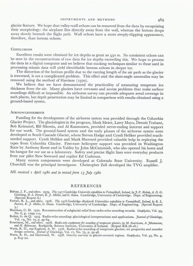
glacier feature. We hope that valley-wall echoes can be removed from the data by recognizing their morphology: the airplane flies directly away from the wall, whereas the bottom drops away slowly beneath the flight path. Wall echoes have a more steeply-dipping appearance, therefore, than bottom echoes.
CONCLUSIONS
Excellent results were obtained for ice depths as great as 550 m. No consistent echoes can be seen in the reconstructions of raw data for ice depths exceeding this. We hope to process the data in a digital computer and we believe that stacking techniques similar to those used in processing seismic data will yield identifiable bottom echoes in deeper ice.
The distortion of the bottom profile due to the varying length of the air path as the glacier is traversed, is not a complicated problem. This effect and the slant-angle anomalies may be removed using the method of Harrison (I 970).
We believe that we have demonstrated the practicality of measuring temperate ice thickness from the air. Many glaciers have crevasses and access problems that make surface soundings difficult or impossible. An airborne survey can provide adequate areal coverage in such places, but depth penetration may be limited in comparison with results obtained using a ground-based system.
ACKNOWLEDGEMENTS
Funding for the development of the airborne system was provided through the Columbia Glacier Project. The glaciologists in the program, Mark Meier, Larry Mayo, Dennis Trabant, Bob Krimmel, Bill Sikonia, and Al Rasmussen, provided never-ending interest and support for our work. The ground-based system and the early phases of the airborne system were developed at South Cascade Glacier, where Steven Hodge and Cyndi Heliker provided muchneeded support. Cyndi Heliker and Mark Sherrard provided valuable help in replaying the tapes from Columbia Glacier. First-rate helicopter support was provided in Washington State by Anthony Reese and in Valdez by John McCammish, who also opened his home and his hangar for our use as a laboratory. Safety and precise flight lines were everyday products from our pilot Stew Steward and copilot Ed Cushman.
Many system components were developed at Colorado State University. Russell J. Churchill was the principal investigator. Christopher Zell developed the TVG amplifier.
MS. received I April 1980 and in revised form 15 July 1980
REFERENCES
Bishop,]. F., and others. 1979. The 1977 Cambridge University expedition to Vatnajiikull, Iceland, by J. F. Bishop, A. D. G. Cumming, R. L. Ferrari, K. J. Miller, and C. Owen. Cambridge, University of Cambridge. Dept. of Engineering. (Special Report 6. )
Ferrari, R. L., and others. 1976. The [976 Cambridge-Rey19avik Universities expedition to Varnajiikull, Iceland, ~v R . L. Ferrari, K. J. Miller, C. Owen. Cambridge, University of Cambridge. Dept. of Engineering. (Special Report 5·)
Harrison, C. H. 1970. Reconstruction of sub glacial relief from radio-echo sounding records. Geophysics, Vol. 35, No. 6, p. 1099-115.
Robin, G. de Q. 1974. Radio-echo sounding: glaciological interpretations and applications. JournalofClaciology, Vol. 15, No. 73, p. 49-64.
Sverrisson, M., and others. 1978. Radio-echo equipmentfor sounding of temperate glaciers, by M. Sverrisson, A. J6hanneson, and H. Bjiirnsson. Reykjavik, Science Institute, University of Iceland. (Report RH-78-16.)
Watts, R. D., and England, A. W. 1976. Radio-echo sounding of temperate glaciers: ice properties and sounder design criteria. Journal of Glaciology, Vol. 17, No. 75, p. 39-48.
Watts, R. D., and Isherwood, W. 1978. Gravity surveys in glacier-covered regions. Geophysics, Vol. 43, No. 4, P· 81 9-22 •