instrumentation filtration products - a.r....
TRANSCRIPT
Bulletin IP-A
InstrumentationFiltration Products
Instrumentation Filters
Parker Hannifin Corporation1-800-C-PARKER
1
Parker’s instrumentation and point-of-use product lineoffers sample filtration solutions for food processing,chemical processing, and compressed natural gasapplications. Typical installations include fast loopsampling, by-pass sampling, protection of high tem-perature sample systems and hydrophobic membranefiltration.
Our unique fiber matrix technology allows us to makehigh efficiency particulate and coalescing filter ele-ments with high void volume yielding lower pressuredrops. Parker’s elements are made from high qualityglass microfiber and are constructed in 2 porositygrades and 3 media types to meet most air/gasapplications.
Our instrumentation filter housings are carefullyengineered to meet critical application specifications.We offer stainless steel housings with various pressureratings and flow for corrosive applications.
Disposable plastic in-lines are offered for low flowapplications. A PTFE housing is available for specialchemical compatibility and corrosion resistanceapplications.
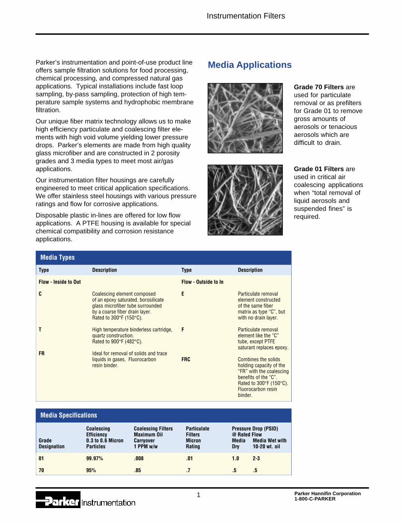
Grade 70 Filters areused for particulateremoval or as prefiltersfor Grade 01 to removegross amounts ofaerosols or tenaciousaerosols which aredifficult to drain.
Media Types
Type Description Type Description
Flow - Inside to Out Flow - Outside to In
C Coalescing element composed E Particulate removalof an epoxy saturated, borosilicate element constructedglass microfiber tube surrounded of the same fiberby a coarse fiber drain layer. matrix as type “C”, butRated to 300°F (150°C). with no drain layer.
T High temperature binderless cartridge, F Particulate removalquartz construction. element like the “C”Rated to 900°F (482°C). tube, except PTFE
saturant replaces epoxy.FR Ideal for removal of solids and trace
liquids in gases. Fluorocarbon FRC Combines the solidsresin binder. holding capacity of the
“FR” with the coalescingbenefits of the “C”.Rated to 300°F (150°C).Fluorocarbon resinbinder.
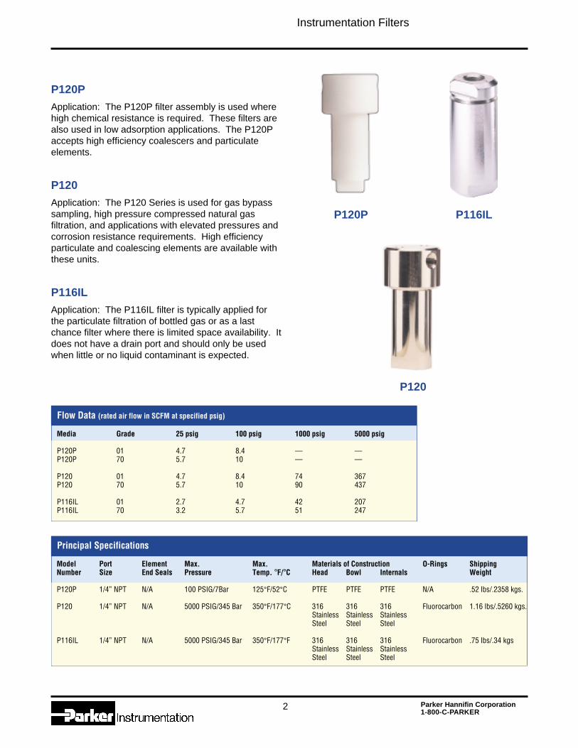
Grade 01 Filters areused in critical aircoalescing applicationswhen “total removal ofliquid aerosols andsuspended fines” isrequired.
Media Applications
Media Specifications
Coalescing Coalescing Filters Particulate Pressure Drop (PSID)Efficiency Maximum Oil Filters @ Rated Flow
Grade 0.3 to 0.6 Micron Carryover Micron Media Media Wet withDesignation Particles 1 PPM w/w Rating Dry 10-20 wt. oil
01 99.97% .008 .01 1.0 2-3
70 95% .85 .7 .5 .5
Instrumentation Filters
Parker Hannifin Corporation1-800-C-PARKER
2
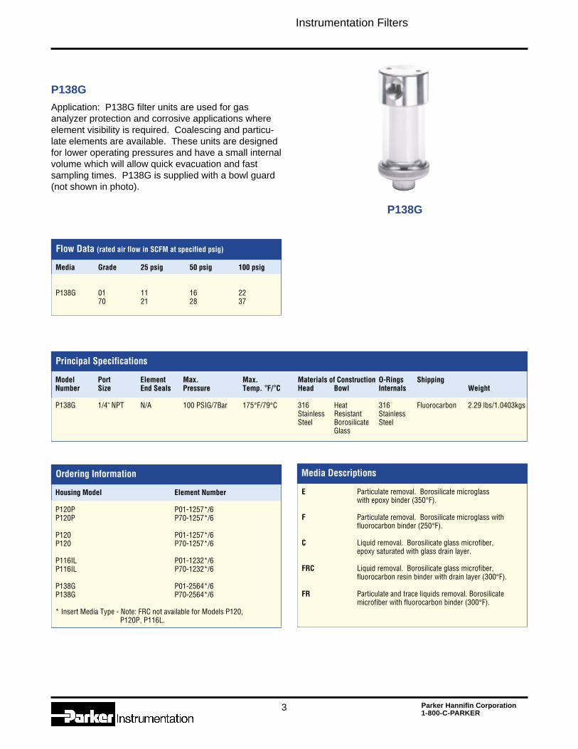
P120PApplication: The P120P filter assembly is used wherehigh chemical resistance is required. These filters arealso used in low adsorption applications. The P120Paccepts high efficiency coalescers and particulateelements.
P120Application: The P120 Series is used for gas bypasssampling, high pressure compressed natural gasfiltration, and applications with elevated pressures andcorrosion resistance requirements. High efficiencyparticulate and coalescing elements are available withthese units.
P116ILApplication: The P116IL filter is typically applied forthe particulate filtration of bottled gas or as a lastchance filter where there is limited space availability. Itdoes not have a drain port and should only be usedwhen little or no liquid contaminant is expected.
Flow Data (rated air flow in SCFM at specified psig)
Principal Specifications
Media Grade 25 psig 100 psig 1000 psig 5000 psig
P120P 01 4.7 8.4 –– ––P120P 70 5.7 10 –– ––
P120 01 4.7 8.4 74 367P120 70 5.7 10 90 437
P116IL 01 2.7 4.7 42 207P116IL 70 3.2 5.7 51 247
P120P
P120
P116IL
Model Port Element Max. Max. Materials of Construction O-Rings ShippingNumber Size End Seals Pressure Temp. °F/°C Head Bowl Internals Weight
P120P 1/4” NPT N/A 100 PSIG/7Bar 125°F/52°C PTFE PTFE PTFE N/A .52 lbs/.2358 kgs.
P120 1/4” NPT N/A 5000 PSIG/345 Bar 350°F/177°C 316 316 316 Fluorocarbon 1.16 lbs/.5260 kgs.Stainless Stainless StainlessSteel Steel Steel
P116IL 1/4” NPT N/A 5000 PSIG/345 Bar 350°F/177°F 316 316 316 Fluorocarbon .75 lbs/.34 kgsStainless Stainless StainlessSteel Steel Steel
Instrumentation Filters
Parker Hannifin Corporation1-800-C-PARKER
3
P138G
Application: P138G filter units are used for gasanalyzer protection and corrosive applications whereelement visibility is required. Coalescing and particu-late elements are available. These units are designedfor lower operating pressures and have a small internalvolume which will allow quick evacuation and fastsampling times. P138G is supplied with a bowl guard(not shown in photo).
Flow Data (rated air flow in SCFM at specified psig)
Principal Specifications
Model Port Element Max. Max. Materials of Construction O-Rings ShippingNumber Size End Seals Pressure Temp. °F/°C Head Bowl Internals Weight
P138G 1/4" NPT N/A 100 PSIG/7Bar 175°F/79°C 316 Heat 316 Fluorocarbon 2.29 lbs/1.0403kgsStainless Resistant StainlessSteel Borosilicate Steel
Glass
Media Grade 25 psig 50 psig 100 psig
P138G 01 11 16 2270 21 28 37
P138G
Ordering Information
Housing Model Element Number
P120P P01-1257*/6P120P P70-1257*/6
P120 P01-1257*/6P120 P70-1257*/6
P116IL P01-1232*/6P116IL P70-1232*/6
P138G P01-2564*/6P138G P70-2564*/6
* Insert Media Type - Note: FRC not available for Models P120, P120P, P116L.
Media Descriptions
E Particulate removal. Borosilicate microglasswith epoxy binder (350°F).
F Particulate removal. Borosilicate microglass withfluorocarbon binder (250°F).
C Liquid removal. Borosilicate glass microfiber,epoxy saturated with glass drain layer.
FRC Liquid removal. Borosilicate glass microfiber,fluorocarbon resin binder with drain layer (300°F).
FR Particulate and trace liquids removal. Borosilicatemicrofiber with fluorocarbon binder (300°F).
Instrumentation Filters
Parker Hannifin Corporation1-800-C-PARKER
4
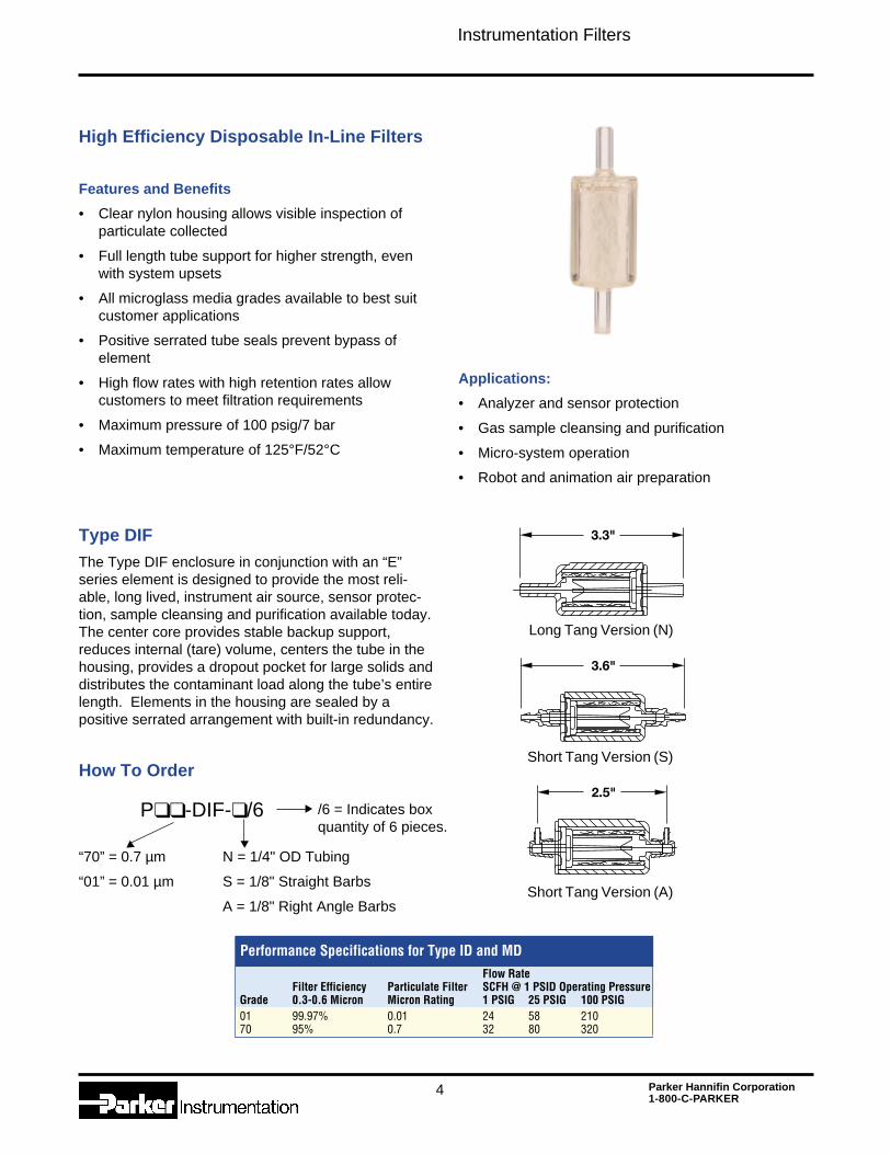
High Efficiency Disposable In-Line Filters
Features and Benefits
• Clear nylon housing allows visible inspection ofparticulate collected
• Full length tube support for higher strength, evenwith system upsets
• All microglass media grades available to best suitcustomer applications
• Positive serrated tube seals prevent bypass ofelement
• High flow rates with high retention rates allowcustomers to meet filtration requirements
• Maximum pressure of 100 psig/7 bar
• Maximum temperature of 125°F/52°C
Type DIFThe Type DIF enclosure in conjunction with an “E”series element is designed to provide the most reli-able, long lived, instrument air source, sensor protec-tion, sample cleansing and purification available today.The center core provides stable backup support,reduces internal (tare) volume, centers the tube in thehousing, provides a dropout pocket for large solids anddistributes the contaminant load along the tube’s entirelength. Elements in the housing are sealed by apositive serrated arrangement with built-in redundancy.
How To Order
“70” = 0.7 µm
“01” = 0.01 µm
P❑❑ -DIF-❑ /6
N = 1/4" OD Tubing
S = 1/8" Straight Barbs
A = 1/8" Right Angle Barbs
/6 = Indicates boxquantity of 6 pieces.
▼ ▼
▼
Applications:
• Analyzer and sensor protection
• Gas sample cleansing and purification
• Micro-system operation
• Robot and animation air preparation
Performance Specifications for Type ID and MDFlow Rate
Filter Efficiency Particulate Filter SCFH @ 1 PSID Operating PressureGrade 0.3-0.6 Micron Micron Rating 1 PSIG 25 PSIG 100 PSIG01 99.97% 0.01 24 58 21070 95% 0.7 32 80 320
Short Tang Version (A)
Short Tang Version (S)
Long Tang Version (N)
Instrumentation Filters
5 Parker Hannifin Corporation1-800-C-PARKER
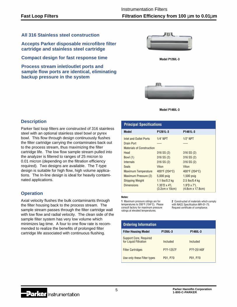
Fast Loop Filters Filtration Efficiency from 100 µm to 0.01µm
All 316 Stainless steel construction
Accepts Parker disposable microfibre filtercartridge and stainless steel cartridge
Compact design for fast response time
Process stream inlet/outlet ports andsample flow ports are identical, eliminatingbackup pressure in the system
Description
Parker fast loop filters are constructed of 316 stainlesssteel with an optional stainless steel bowl or pyrexbowl. This flow through design continuously flushesthe filter cartridge carrying the contaminates back outto the process stream, thus maximizing the filtercartridge life. The low flow sample stream pulled intothe analyzer is filtered to ranges of 25 micron to0.01 micron (depending on the filtration efficiencyrequired). Two designs are available. The T-typedesign is suitable for high flow, high volume applica-tions. The In-line design is ideal for heavily contami-nated applications.
Operation
Axial velocity flushes the bulk contaminants throughthe filter housing back to the process stream. Thesample stream passes through the filter cartridge wallwith low flow and radial velocity. The clean side of thesample filter system has very low volume whichminimizes lag time. A four to one flow rate is recom-mended to realize the benefits of prolonged filtercartridge life associated with continuous flushing.
Model P126IL-3
Model P146IL-3
Model P1261L-3 P1461L-3
Inlet and Outlet Ports 1/4" NPT 1/2" NPTDrain Port ––– –––Materials of ConstructionHead 316 SS (2) 316 SS (2)Bowl (1) 316 SS (2) 316 SS (2)Internals 316 SS (2) 316 SS (2)Seals Viton VitonMaximum Temperature 400°F (204°C) 400°F (204°C)Maximum Pressure (2) 5,000 psig 1,500 psigShipping Weight 1.1 lbs/0.2 kg 2.5 lbs/0.4 kgDimensions 1.35"D x 4"L 1.9"D x 7"L
(3.2cm x 10cm) (4.8cm x 17.8cm)
Principal Specifications
Notes:
1 Maximum pressure ratings are fortemperatures to 200°F (104°C). Pleaseconsult factory for maximum pressureratings at elevated temperatures.
Ordering Information
Filter Housing Model P126IL-3 P146IL-3
Support Core, Requiredfor Liquid Filtration Included Included
Filter Cartridges P??-1257F P??-25140F
Use only these Filter types P01, P70 P01, P70
2 Constructed of materials which complywith NACE Specification MR-01-75.Request certificate of compliance.
Instrumentation Filters
6 Parker Hannifin Corporation1-800-C-PARKER
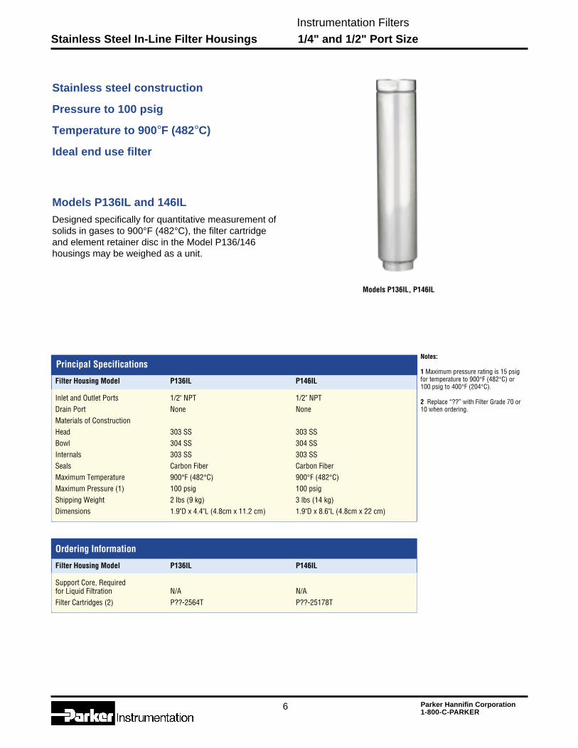
Stainless Steel In-Line Filter Housings 1/4" and 1/2" Port Size
Ordering Information
Filter Housing Model P136IL P146IL
Support Core, Requiredfor Liquid Filtration N/A N/AFilter Cartridges (2) P??-2564T P??-25178T
Stainless steel construction
Pressure to 100 psig
Temperature to 900°F (482°C)
Ideal end use filter
Models P136IL and 146ILDesigned specifically for quantitative measurement ofsolids in gases to 900°F (482°C), the filter cartridgeand element retainer disc in the Model P136/146housings may be weighed as a unit.
Models P136IL, P146IL
Principal SpecificationsNotes:
1 Maximum pressure rating is 15 psigfor temperature to 900°F (482°C) or100 psig to 400°F (204°C).
2 Replace “??” with Filter Grade 70 or10 when ordering.
Filter Housing Model P136IL P146IL
Inlet and Outlet Ports 1/2" NPT 1/2" NPTDrain Port None NoneMaterials of ConstructionHead 303 SS 303 SSBowl 304 SS 304 SSInternals 303 SS 303 SSSeals Carbon Fiber Carbon FiberMaximum Temperature 900°F (482°C) 900°F (482°C)Maximum Pressure (1) 100 psig 100 psigShipping Weight 2 lbs (9 kg) 3 lbs (14 kg)Dimensions 1.9"D x 4.4"L (4.8cm x 11.2 cm) 1.9"D x 8.6"L (4.8cm x 22 cm)
Instrumentation Filters
7 Parker Hannifin Corporation1-800-C-PARKER
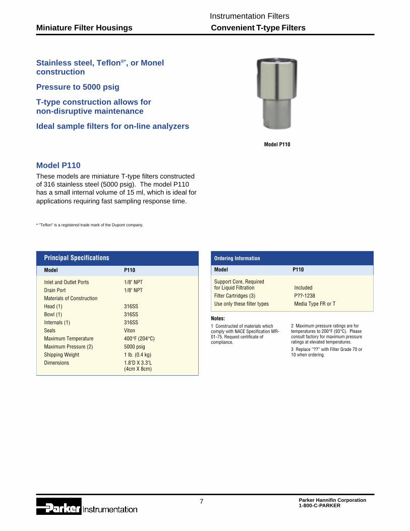
Miniature Filter Housings Convenient T-type Filters
Model P110
Stainless steel, Teflon®*, or Monelconstruction
Pressure to 5000 psig
T-type construction allows fornon-disruptive maintenance
Ideal sample filters for on-line analyzers
Principal Specifications
Model P110
Inlet and Outlet Ports 1/8" NPTDrain Port 1/8" NPTMaterials of ConstructionHead (1) 316SSBowl (1) 316SSInternals (1) 316SSSeals VitonMaximum Temperature 400°F (204°C)Maximum Pressure (2) 5000 psigShipping Weight 1 lb. (0.4 kg)Dimensions 1.8"D X 3.3"L
(4cm X 8cm)
Notes:1 Constructed of materials whichcomply with NACE Specification MR-01-75. Request certificate ofcompliance.
Ordering Information
Ordering Information
Model P110
Support Core, Requiredfor Liquid Filtration IncludedFilter Cartridges (3) P??-1238Use only these filter types Media Type FR or T
Model P110
These models are miniature T-type filters constructedof 316 stainless steel (5000 psig). The model P110has a small internal volume of 15 ml, which is ideal forapplications requiring fast sampling response time.
2 Maximum pressure ratings are fortemperatures to 200°F (93°C). Pleaseconsult factory for maximum pressureratings at elevated temperatures.
3 Replace “??” with Filter Grade 70 or10 when ordering.
* "Teflon" is a registered trade mark of the Dupont company.
Instrumentation Filters
8 Parker Hannifin Corporation1-800-C-PARKER
Series P101 Membrane Filters Hydrophobic Membrane Protection
Series P101 Membrane Filter
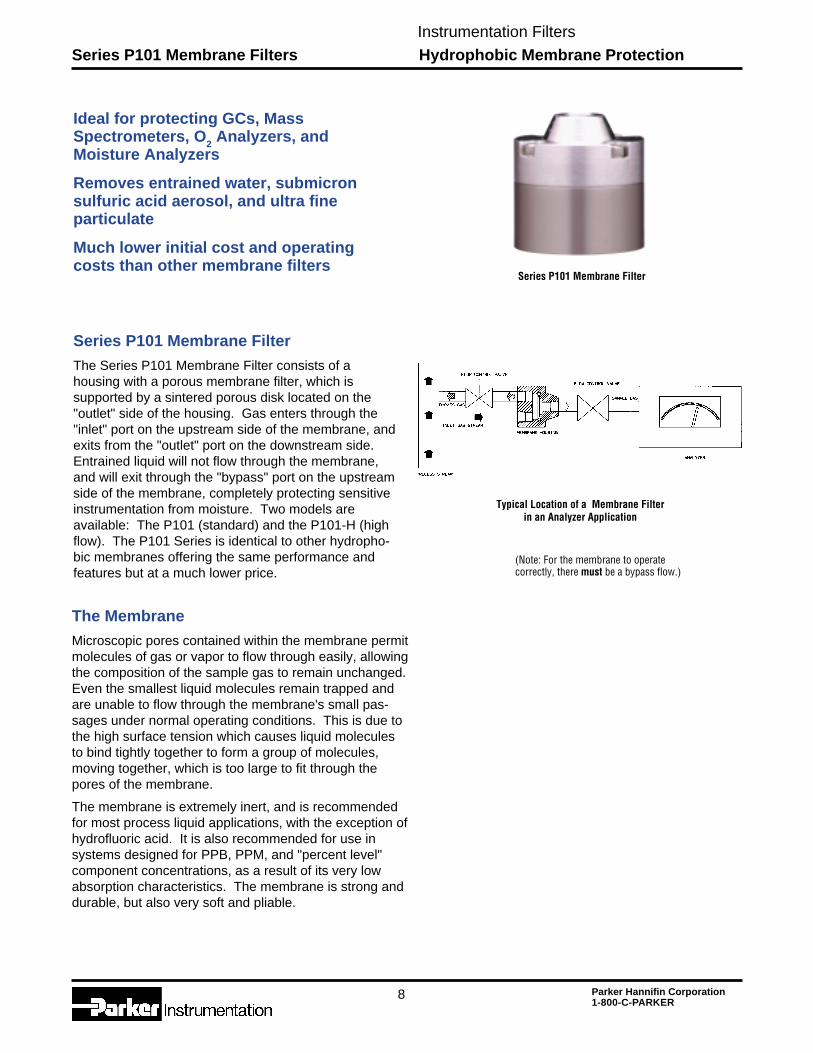
The Series P101 Membrane Filter consists of ahousing with a porous membrane filter, which issupported by a sintered porous disk located on the"outlet" side of the housing. Gas enters through the"inlet" port on the upstream side of the membrane, andexits from the "outlet" port on the downstream side.Entrained liquid will not flow through the membrane,and will exit through the "bypass" port on the upstreamside of the membrane, completely protecting sensitiveinstrumentation from moisture. Two models areavailable: The P101 (standard) and the P101-H (highflow). The P101 Series is identical to other hydropho-bic membranes offering the same performance andfeatures but at a much lower price.
The Membrane
Microscopic pores contained within the membrane permitmolecules of gas or vapor to flow through easily, allowingthe composition of the sample gas to remain unchanged.Even the smallest liquid molecules remain trapped andare unable to flow through the membrane's small pas-sages under normal operating conditions. This is due tothe high surface tension which causes liquid moleculesto bind tightly together to form a group of molecules,moving together, which is too large to fit through thepores of the membrane.
The membrane is extremely inert, and is recommendedfor most process liquid applications, with the exception ofhydrofluoric acid. It is also recommended for use insystems designed for PPB, PPM, and "percent level"component concentrations, as a result of its very lowabsorption characteristics. The membrane is strong anddurable, but also very soft and pliable.
Ideal for protecting GCs, MassSpectrometers, O2 Analyzers, andMoisture Analyzers
Removes entrained water, submicronsulfuric acid aerosol, and ultra fineparticulate
Much lower initial cost and operatingcosts than other membrane filters
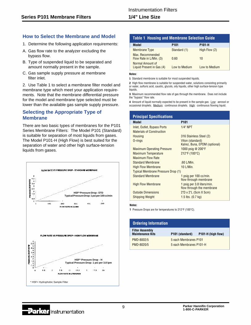
(Note: For the membrane to operatecorrectly, there must be a bypass flow.)
Series P101 Membrane Filter
Typical Location of a Membrane Filterin an Analyzer Application
Instrumentation Filters
9 Parker Hannifin Corporation1-800-C-PARKER
How to Select the Membrane and Model1. Determine the following application requirements:
A. Gas flow rate to the analyzer excluding thebypass flow.
B. Type of suspended liquid to be separated andamount normally present in the sample.
C. Gas sample supply pressure at membranefilter inlet.
2. Use Table 1 to select a membrane filter model andmembrane type which meet your application require-ments. Note that the membrane differential pressurefor the model and membrane type selected must belower than the available gas sample supply pressure.
Selecting the Appropriate Type ofMembrane
There are two basic types of membranes for the P101Series Membrane Filters: The Model P101 (Standard)is suitable for separation of most liquids from gases.The Model P101-H (High Flow) is best suited for theseparation of water and other high surface-tensionliquids from gases.
Table 1 Housing and Membrane Selection Guide
Model P101 P101-HMembrane Type Standard (1) High Flow (2)Max. RecommendedFlow Rate in L/Min. (3) 0.60 10Normal Amount ofLiquid Present in Gas (4) Low to Medium Low to Medium
Principal SpecificationsModel P101Inlet, Outlet, Bypass Ports 1/4" NPTMaterials of ConstructionHousing 316 Stainless Steel (2)O-rings Viton (standard)
Kalrez, Buna, EPDM (optional)Maximum Operating Pressure 1000 psig @ 200°FMaximum Temperature 212°F (100°C)Maximum Flow RateStandard Membrane .60 L/Min.High Flow Membrane 10 L/Min.Typical Membrane Pressure Drop (1)Standard Membrane 1 psig per 100 cc/min.
flow through membraneHigh Flow Membrane 1 psig per 3.8 liters/min.
flow through the membraneOutside Dimensions 2"D x 2"L (5cm X 5cm)Shipping Weight 1.5 lbs. (0.7 kg)
Notes:
1 Pressure Drops are for temperatures to 212°F (100°C).
Ordering Information
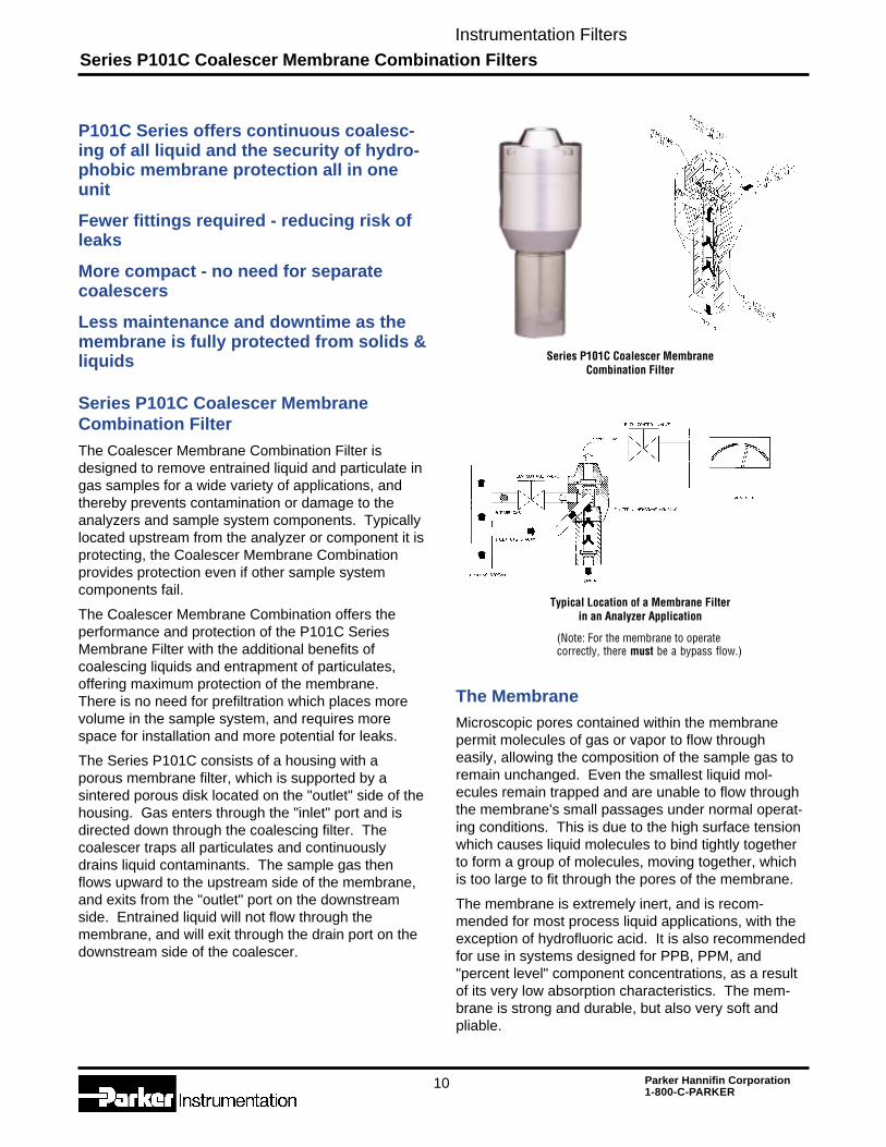
HSF* Pressure Drop - STDTypical Pressure Drop: 1 psi per 100 cc/min
HSF* Pressure Drop - HTypical Pressure Drop: 1 psi per 3.8 lpm
* HSF= Hydrophobic Sample Filter
Series P101 Membrane Filters 1/4" Line Size
Notes:
1 Standard membrane is suitable for most suspended liquids.
2 High flow membrane is suitable for suspended water, solutions consisting primarilyor water, sulfuric acid, caustic, glycols, oily liquids, other high surface-tension typeliquids.
3 Maximum recommended flow rate of gas through the membrane. Does not includethe “bypass” flow rate.
4 Amount of liquid normally expected to be present in the sample gas: Low: aerosol oroccasional droplets. Medium: continuous droplets. High: continuous flowing liquid.
Filter AssemblyMaintenance Kits P101 (standard) P101-H (high flow)
PMD-8002/5 5 each Membranes P101PMD-8020/5 5 each Membranes P101-H
Instrumentation Filters
10 Parker Hannifin Corporation1-800-C-PARKER
Series P101C Coalescer Membrane Combination Filters
P101C Series offers continuous coalesc-ing of all liquid and the security of hydro-phobic membrane protection all in oneunit
Fewer fittings required - reducing risk ofleaks
More compact - no need for separatecoalescers
Less maintenance and downtime as themembrane is fully protected from solids &liquids
Series P101C Coalescer MembraneCombination FilterThe Coalescer Membrane Combination Filter isdesigned to remove entrained liquid and particulate ingas samples for a wide variety of applications, andthereby prevents contamination or damage to theanalyzers and sample system components. Typicallylocated upstream from the analyzer or component it isprotecting, the Coalescer Membrane Combinationprovides protection even if other sample systemcomponents fail.
The Coalescer Membrane Combination offers theperformance and protection of the P101C SeriesMembrane Filter with the additional benefits ofcoalescing liquids and entrapment of particulates,offering maximum protection of the membrane.There is no need for prefiltration which places morevolume in the sample system, and requires morespace for installation and more potential for leaks.
The Series P101C consists of a housing with aporous membrane filter, which is supported by asintered porous disk located on the "outlet" side of thehousing. Gas enters through the "inlet" port and isdirected down through the coalescing filter. Thecoalescer traps all particulates and continuouslydrains liquid contaminants. The sample gas thenflows upward to the upstream side of the membrane,and exits from the "outlet" port on the downstreamside. Entrained liquid will not flow through themembrane, and will exit through the drain port on thedownstream side of the coalescer.
The MembraneMicroscopic pores contained within the membranepermit molecules of gas or vapor to flow througheasily, allowing the composition of the sample gas toremain unchanged. Even the smallest liquid mol-ecules remain trapped and are unable to flow throughthe membrane's small passages under normal operat-ing conditions. This is due to the high surface tensionwhich causes liquid molecules to bind tightly togetherto form a group of molecules, moving together, whichis too large to fit through the pores of the membrane.
The membrane is extremely inert, and is recom-mended for most process liquid applications, with theexception of hydrofluoric acid. It is also recommendedfor use in systems designed for PPB, PPM, and"percent level" component concentrations, as a resultof its very low absorption characteristics. The mem-brane is strong and durable, but also very soft andpliable.
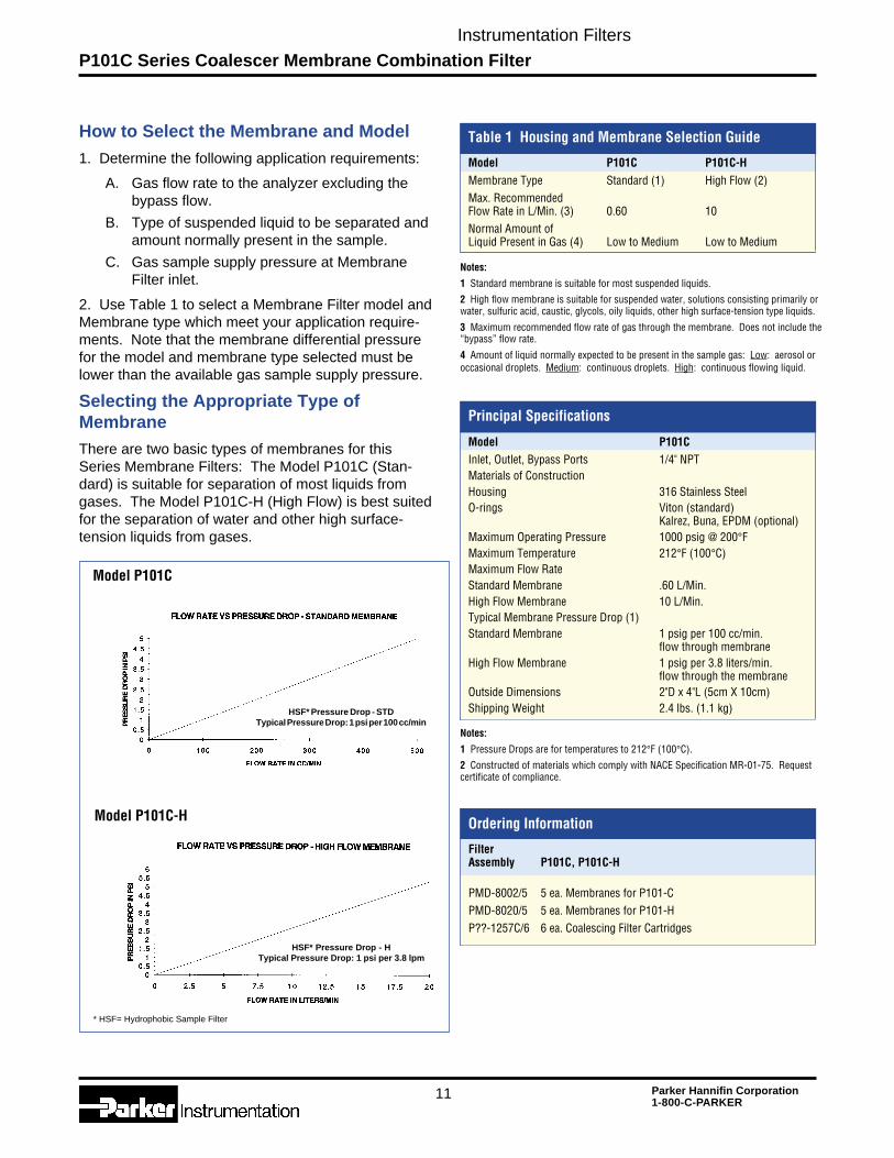
Series P101C Coalescer MembraneCombination Filter
Typical Location of a Membrane Filterin an Analyzer Application
(Note: For the membrane to operatecorrectly, there must be a bypass flow.)
Instrumentation Filters
11 Parker Hannifin Corporation1-800-C-PARKER
P101C Series Coalescer Membrane Combination Filter
How to Select the Membrane and Model
1. Determine the following application requirements:
A. Gas flow rate to the analyzer excluding thebypass flow.
B. Type of suspended liquid to be separated andamount normally present in the sample.
C. Gas sample supply pressure at MembraneFilter inlet.
2. Use Table 1 to select a Membrane Filter model andMembrane type which meet your application require-ments. Note that the membrane differential pressurefor the model and membrane type selected must belower than the available gas sample supply pressure.
Selecting the Appropriate Type ofMembraneThere are two basic types of membranes for thisSeries Membrane Filters: The Model P101C (Stan-dard) is suitable for separation of most liquids fromgases. The Model P101C-H (High Flow) is best suitedfor the separation of water and other high surface-tension liquids from gases.
Table 1 Housing and Membrane Selection Guide
Model P101C P101C-HMembrane Type Standard (1) High Flow (2)Max. RecommendedFlow Rate in L/Min. (3) 0.60 10Normal Amount ofLiquid Present in Gas (4) Low to Medium Low to Medium
Model P101C
Model P101C-H
Notes:
1 Standard membrane is suitable for most suspended liquids.
2 High flow membrane is suitable for suspended water, solutions consisting primarily orwater, sulfuric acid, caustic, glycols, oily liquids, other high surface-tension type liquids.
3 Maximum recommended flow rate of gas through the membrane. Does not include the“bypass” flow rate.
4 Amount of liquid normally expected to be present in the sample gas: Low: aerosol oroccasional droplets. Medium: continuous droplets. High: continuous flowing liquid.
HSF* Pressure Drop - STDTypical Pressure Drop: 1 psi per 100 cc/min
HSF* Pressure Drop - HTypical Pressure Drop: 1 psi per 3.8 lpm
Principal Specifications
Model P101CInlet, Outlet, Bypass Ports 1/4" NPTMaterials of ConstructionHousing 316 Stainless SteelO-rings Viton (standard)
Kalrez, Buna, EPDM (optional)Maximum Operating Pressure 1000 psig @ 200°FMaximum Temperature 212°F (100°C)Maximum Flow RateStandard Membrane .60 L/Min.High Flow Membrane 10 L/Min.Typical Membrane Pressure Drop (1)Standard Membrane 1 psig per 100 cc/min.
flow through membraneHigh Flow Membrane 1 psig per 3.8 liters/min.
flow through the membraneOutside Dimensions 2"D x 4"L (5cm X 10cm)Shipping Weight 2.4 lbs. (1.1 kg)
Notes:
1 Pressure Drops are for temperatures to 212°F (100°C).
2 Constructed of materials which comply with NACE Specification MR-01-75. Requestcertificate of compliance.
Ordering Information
FilterAssembly P101C, P101C-H
PMD-8002/5 5 ea. Membranes for P101-CPMD-8020/5 5 ea. Membranes for P101-HP??-1257C/6 6 ea. Coalescing Filter Cartridges
* HSF= Hydrophobic Sample Filter
Instrumentation Filters
12 Parker Hannifin Corporation1-800-C-PARKER
P130C Series Coalescer Membrane Combination Filters
Page 25
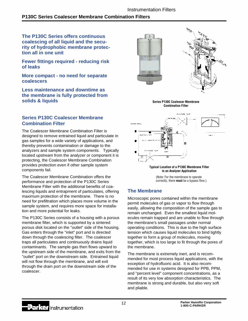
The P130C Series offers continuouscoalescing of all liquid and the secu-rity of hydrophobic membrane protec-tion all in one unit
Fewer fittings required - reducing riskof leaks
More compact - no need for separatecoalescers
Less maintenance and downtime asthe membrane is fully protected fromsolids & liquids
Series P130C Coalescer MembraneCombination FilterThe Coalescer Membrane Combination Filter isdesigned to remove entrained liquid and particulate ingas samples for a wide variety of applications, andthereby prevents contamination or damage to theanalyzers and sample system components. Typicallylocated upstream from the analyzer or component it isprotecting, the Coalescer Membrane Combinationprovides protection even if other sample systemcomponents fail.
The Coalescer Membrane Combination offers theperformance and protection of the P130C SeriesMembrane Filter with the additional benefits of coa-lescing liquids and entrapment of particulates, offeringmaximum protection of the membrane. There is noneed for prefiltration which places more volume in thesample system, and requires more space for installa-tion and more potential for leaks.
The P130C Series consists of a housing with a porousmembrane filter, which is supported by a sinteredporous disk located on the "outlet" side of the housing.Gas enters through the "inlet" port and is directeddown through the coalescing filter. The coalescertraps all particulates and continuously drains liquidcontaminants. The sample gas then flows upward tothe upstream side of the membrane, and exits from the"outlet" port on the downstream side. Entrained liquidwill not flow through the membrane, and will exitthrough the drain port on the downstream side of thecoalescer.
The MembraneMicroscopic pores contained within the membranepermit molecules of gas or vapor to flow througheasily, allowing the composition of the sample gas toremain unchanged. Even the smallest liquid mol-ecules remain trapped and are unable to flow throughthe membrane's small passages under normaloperating conditions. This is due to the high surfacetension which causes liquid molecules to bind tightlytogether to form a group of molecules, movingtogether, which is too large to fit through the pores ofthe membrane.
The membrane is extremely inert, and is recom-mended for most process liquid applications, with theexception of hydrofluoric acid. It is also recom-mended for use in systems designed for PPB, PPM,and "percent level" component concentrations, as aresult of its very low absorption characteristics. Themembrane is strong and durable, but also very softand pliable.
Series P130C Coalescer MembraneCombination Filter
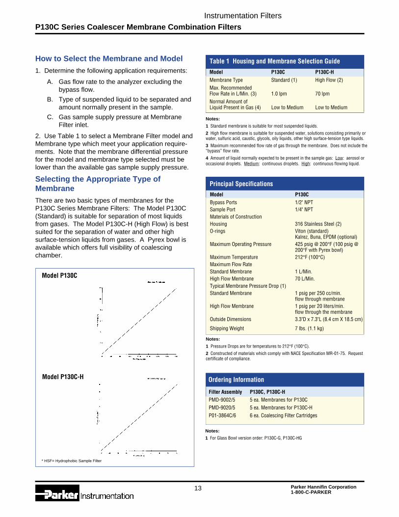
Typical Location of a P130C Membrane Filterin an Analyzer Application
(Note: For the membrane to operatecorrectly, there must be a bypass flow.)
Instrumentation Filters
13 Parker Hannifin Corporation1-800-C-PARKER
P130C Series Coalescer Membrane Combination Filters
How to Select the Membrane and Model1. Determine the following application requirements:
A. Gas flow rate to the analyzer excluding thebypass flow.
B. Type of suspended liquid to be separated andamount normally present in the sample.
C. Gas sample supply pressure at MembraneFilter inlet.
2. Use Table 1 to select a Membrane Filter model andMembrane type which meet your application require-ments. Note that the membrane differential pressurefor the model and membrane type selected must belower than the available gas sample supply pressure.
Selecting the Appropriate Type ofMembraneThere are two basic types of membranes for theP130C Series Membrane Filters: The Model P130C(Standard) is suitable for separation of most liquidsfrom gases. The Model P130C-H (High Flow) is bestsuited for the separation of water and other highsurface-tension liquids from gases. A Pyrex bowl isavailable which offers full visibility of coalescingchamber.
Table 1 Housing and Membrane Selection Guide
Model P130C P130C-HMembrane Type Standard (1) High Flow (2)Max. RecommendedFlow Rate in L/Min. (3) 1.0 lpm 70 lpmNormal Amount ofLiquid Present in Gas (4) Low to Medium Low to Medium
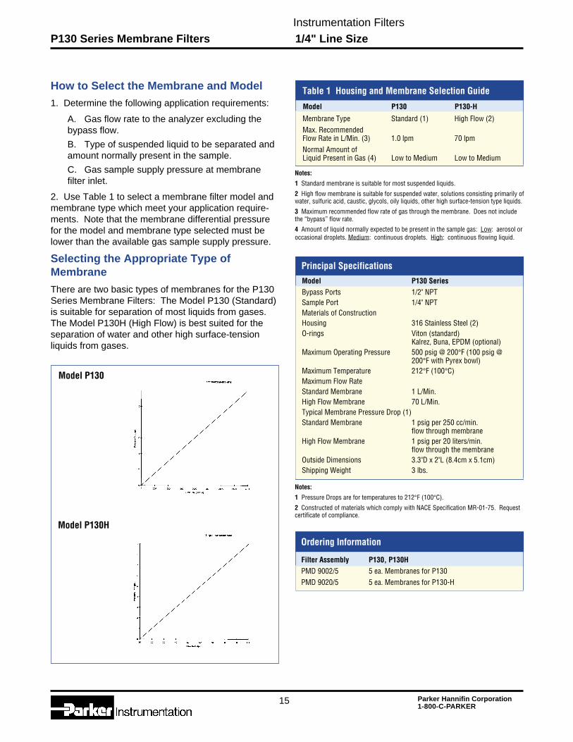
Model P130C
Model P130C-H
Notes:
1 Standard membrane is suitable for most suspended liquids.
2 High flow membrane is suitable for suspended water, solutions consisting primarily orwater, sulfuric acid, caustic, glycols, oily liquids, other high surface-tension type liquids.
3 Maximum recommended flow rate of gas through the membrane. Does not include the“bypass” flow rate.
4 Amount of liquid normally expected to be present in the sample gas: Low: aerosol oroccasional droplets. Medium: continuous droplets. High: continuous flowing liquid.
Principal Specifications
Model P130CBypass Ports 1/2" NPTSample Port 1/4" NPTMaterials of ConstructionHousing 316 Stainless Steel (2)O-rings Viton (standard)
Kalrez, Buna, EPDM (optional)Maximum Operating Pressure 425 psig @ 200°F (100 psig @
200°F with Pyrex bowl)Maximum Temperature 212°F (100°C)Maximum Flow RateStandard Membrane 1 L/Min.High Flow Membrane 70 L/Min.Typical Membrane Pressure Drop (1)Standard Membrane 1 psig per 250 cc/min.
flow through membraneHigh Flow Membrane 1 psig per 20 liters/min.
flow through the membraneOutside Dimensions 3.3"D x 7.3"L (8.4 cm X 18.5 cm)
Shipping Weight 7 lbs. (1.1 kg)
Notes:
1 Pressure Drops are for temperatures to 212°F (100°C).
2 Constructed of materials which comply with NACE Specification MR-01-75. Requestcertificate of compliance.
Ordering Information
Filter Assembly P130C, P130C-HPMD-9002/5 5 ea. Membranes for P130CPMD-9020/5 5 ea. Membranes for P130C-HP01-3864C/6 6 ea. Coalescing Filter Cartridges
* HSF= Hydrophobic Sample Filter
Notes:
1 For Glass Bowl version order: P130C-G, P130C-HG
Instrumentation Filters
14 Parker Hannifin Corporation1-800-C-PARKER
P130 Series Membrane Filters
The P130 Series Membrane FilterThe P130 Series Membrane Filter consists of ahousing with a porous membrane filter, which issupported by a sintered porous disk located on the"outlet" side of the housing. Gas enters through the"inlet" port on the upstream side of the membrane, andexits from the "outlet" port on the downstream side.Entrained liquid will not flow through the membrane,and will exit through the "bypass" port on the upstreamside of the membrane, completely protecting sensitiveinstrumentation from moisture. Two models areavailable: P130 (standard) and the P130H (high flow).The P130 Series is identical to other hydrophobicmembranes offering the same performance andfeatures but at a much lower price.
The Membrane
Microscopic pores contained within the membranepermit molecules of gas or vapor to flow througheasily, allowing the composition of the sample gas toremain unchanged. Even the smallest liquid mol-ecules remain trapped and are unable to flow throughthe membrane's small passages under normal operat-ing conditions. This is due to the high surface tensionwhich causes liquid molecules to bind tightly togetherto form a group of molecules, moving together, whichis too large to fit through the pores of the membrane.
The membrane is extremely inert, and is recom-mended for most process liquid applications, with theexception of hydrofluoric acid. It is also recommendedfor use in systems designed for PPB, PPM, and"percent level" component concentrations, as a resultof its very low absorption characteristics. The mem-brane is strong and durable, but also very soft andpliable.
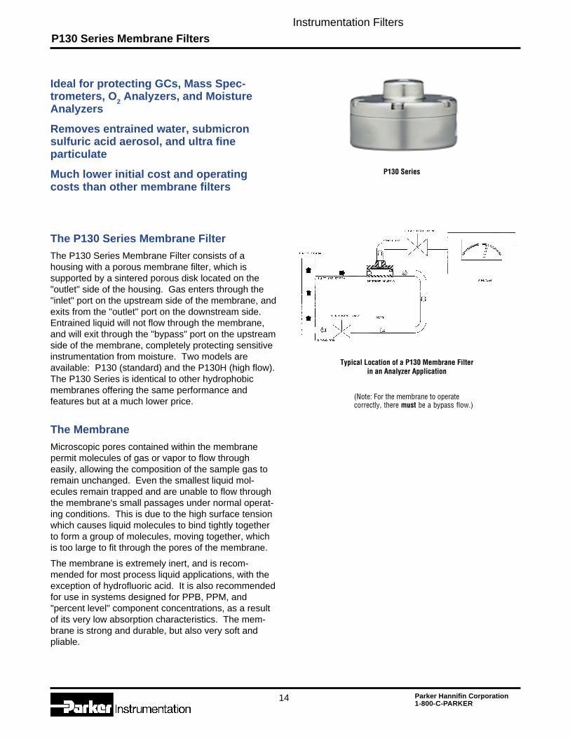
Ideal for protecting GCs, Mass Spec-trometers, O2 Analyzers, and MoistureAnalyzers
Removes entrained water, submicronsulfuric acid aerosol, and ultra fineparticulate
Much lower initial cost and operatingcosts than other membrane filters
P130 Series
(Note: For the membrane to operatecorrectly, there must be a bypass flow.)
Typical Location of a P130 Membrane Filterin an Analyzer Application
Instrumentation Filters
15 Parker Hannifin Corporation1-800-C-PARKER
Membrane Type Standard (1) High Flow (2)Max. RecommendedFlow Rate in L/Min. (3) 1.0 lpm 70 lpmNormal Amount ofLiquid Present in Gas (4) Low to Medium Low to Medium
How to Select the Membrane and Model1. Determine the following application requirements:
A. Gas flow rate to the analyzer excluding thebypass flow.
B. Type of suspended liquid to be separated andamount normally present in the sample.
C. Gas sample supply pressure at membranefilter inlet.
2. Use Table 1 to select a membrane filter model andmembrane type which meet your application require-ments. Note that the membrane differential pressurefor the model and membrane type selected must belower than the available gas sample supply pressure.
Selecting the Appropriate Type ofMembrane
There are two basic types of membranes for the P130Series Membrane Filters: The Model P130 (Standard)is suitable for separation of most liquids from gases.The Model P130H (High Flow) is best suited for theseparation of water and other high surface-tensionliquids from gases.
Table 1 Housing and Membrane Selection Guide
Model P130 P130-H
Notes:
1 Standard membrane is suitable for most suspended liquids.
2 High flow membrane is suitable for suspended water, solutions consisting primarily ofwater, sulfuric acid, caustic, glycols, oily liquids, other high surface-tension type liquids.
3 Maximum recommended flow rate of gas through the membrane. Does not includethe “bypass” flow rate.
4 Amount of liquid normally expected to be present in the sample gas: Low: aerosol oroccasional droplets. Medium: continuous droplets. High: continuous flowing liquid.
Principal Specifications
Notes:
1 Pressure Drops are for temperatures to 212°F (100°C).
2 Constructed of materials which comply with NACE Specification MR-01-75. Requestcertificate of compliance.
Ordering Information
Model P130
Model P130H
Model P130 SeriesBypass Ports 1/2" NPTSample Port 1/4" NPTMaterials of ConstructionHousing 316 Stainless Steel (2)O-rings Viton (standard)
Kalrez, Buna, EPDM (optional)Maximum Operating Pressure 500 psig @ 200°F (100 psig @
200°F with Pyrex bowl)Maximum Temperature 212°F (100°C)Maximum Flow RateStandard Membrane 1 L/Min.High Flow Membrane 70 L/Min.Typical Membrane Pressure Drop (1)Standard Membrane 1 psig per 250 cc/min.
flow through membraneHigh Flow Membrane 1 psig per 20 liters/min.
flow through the membraneOutside Dimensions 3.3"D x 2"L (8.4cm x 5.1cm)Shipping Weight 3 lbs.
Filter Assembly P130, P130HPMD 9002/5 5 ea. Membranes for P130PMD 9020/5 5 ea. Membranes for P130-H
P130 Series Membrane Filters 1/4" Line Size
Instrumentation Filters
16 Parker Hannifin Corporation1-800-C-PARKER
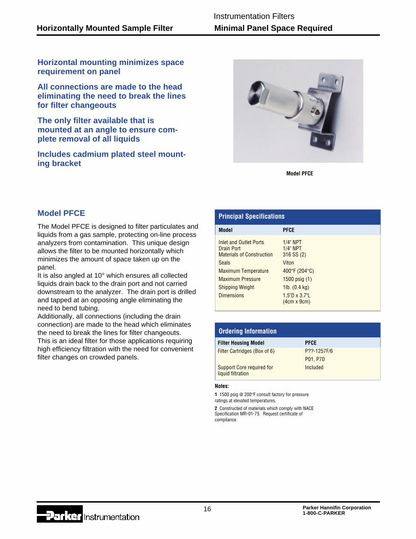
Model PFCE
Horizontal mounting minimizes spacerequirement on panel
All connections are made to the headeliminating the need to break the linesfor filter changeouts
The only filter available that ismounted at an angle to ensure com-plete removal of all liquids
Includes cadmium plated steel mount-ing bracket
The Model PFCE is designed to filter particulates andliquids from a gas sample, protecting on-line processanalyzers from contamination. This unique designallows the filter to be mounted horizontally whichminimizes the amount of space taken up on thepanel.It is also angled at 10° which ensures all collectedliquids drain back to the drain port and not carrieddownstream to the analyzer. The drain port is drilledand tapped at an opposing angle eliminating theneed to bend tubing.Additionally, all connections (including the drainconnection) are made to the head which eliminatesthe need to break the lines for filter changeouts.This is an ideal filter for those applications requiringhigh efficiency filtration with the need for convenientfilter changes on crowded panels.
Model PFCE
Principal Specifications
Model PFCE
Inlet and Outlet Ports 1/4" NPTDrain Port 1/4" NPTMaterials of Construction 316 SS (2)Seals VitonMaximum Temperature 400°F (204°C)Maximum Pressure 1500 psig (1)Shipping Weight 1lb. (0.4 kg)Dimensions 1.5"D x 3.7"L
(4cm x 9cm)
Notes:1 1500 psig @ 200°F consult factory for pressureratings at elevated temperatures.
2 Constructed of materials which comply with NACESpecification MR-01-75. Request certificate ofcompliance.
Ordering Information
Horizontally Mounted Sample Filter Minimal Panel Space Required
Filter Housing Model PFCEFilter Cartridges (Box of 6) P??-1257F/6
P01, P70Support Core required for Includedliquid filtration
Instrumentation Filters
17 Parker Hannifin Corporation1-800-C-PARKER
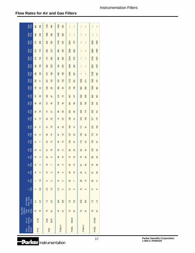
Flow Rates for Air and Gas Filters
Flow
Rat
e(C
FM) a
tFi
lter
Vol.
ofFi
lter
10°F
Wat
erHo
usin
gHo
usin
gTu
bePr
ess.
Dro
p2
2040
6080
100
125
150
200
250
300
500
750
1000
1500
2000
2500
3000
3500
4000
4500
5000
Mod
el(m
l)Gr
ade
0 ps
igPS
IGPS
IGPS
IGPS
IGPS
IGPS
IGPS
IGPS
IGPS
IGPS
IGPS
IGPS
IGPS
IGPS
IGPS
IGPS
IGPS
IGPS
IGPS
IGPS
IGPS
IGPS
IG
700.
73
710
1418
2227
3241
5160
9914
719
529
038
648
257
867
477
088
696
2P1
1011
.33
700.
20.
91.
83
45
67
911
1416
2639
5277
103
128
154
179
205
230
256
19.8
270
1.5
3.9
813
1822
2733
3951
6274
121
180
239
357
470
590
710
830
940
1060
1180
PFCE
36.8
101
0.3
1.5
35
78
1012
1419
2327
4567
8813
218
022
026
031
035
039
044
0
70N/
A2.
510
1623
2833
4047
6175
8914
521
028
042
056
070
084
098
011
2012
6014
00P1
26IL
-301
N/A
25
89
1011
1316
2025
2946
7090
130
180
220
260
300
340
380
420
703.
012
2640
5570
8510
312
215
919
623
338
156
775
211
2214
9318
6322
3426
0029
70––
––P1
36IL
158.
5801
0.5
37
1014
1822
2732
4151
6099
147
195
291
387
483
579
695
770
––––
70N?
A13
2845
6178
9411
513
517
721
825
942
362
983
412
45––
––––
––––
––––
P146
IL-3
01N/
A6
1321
2835
4353
6281
100
119
194
288
383
571
––––
––––
––––
––
707.
517
3657
7899
120
146
172
225
277
329
538
800
1062
1585
2108
2631
3156
3680
4200
––––
P146
IL41
9.09
011.
38
1726
3645
5567
7910
312
715
124
736
748
772
796
712
0714
4716
9019
30––
––
Instrumentation Filters
18 Parker Hannifin Corporation1-800-C-PARKER
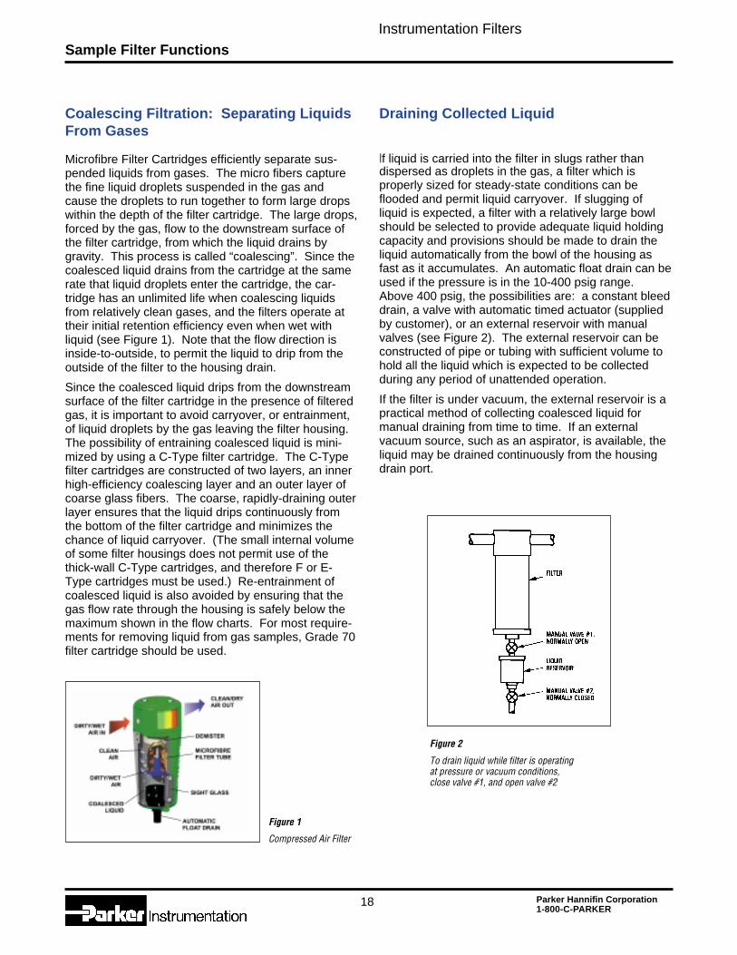
Microfibre Filter Cartridges efficiently separate sus-pended liquids from gases. The micro fibers capturethe fine liquid droplets suspended in the gas andcause the droplets to run together to form large dropswithin the depth of the filter cartridge. The large drops,forced by the gas, flow to the downstream surface ofthe filter cartridge, from which the liquid drains bygravity. This process is called “coalescing”. Since thecoalesced liquid drains from the cartridge at the samerate that liquid droplets enter the cartridge, the car-tridge has an unlimited life when coalescing liquidsfrom relatively clean gases, and the filters operate attheir initial retention efficiency even when wet withliquid (see Figure 1). Note that the flow direction isinside-to-outside, to permit the liquid to drip from theoutside of the filter to the housing drain.
Since the coalesced liquid drips from the downstreamsurface of the filter cartridge in the presence of filteredgas, it is important to avoid carryover, or entrainment,of liquid droplets by the gas leaving the filter housing.The possibility of entraining coalesced liquid is mini-mized by using a C-Type filter cartridge. The C-Typefilter cartridges are constructed of two layers, an innerhigh-efficiency coalescing layer and an outer layer ofcoarse glass fibers. The coarse, rapidly-draining outerlayer ensures that the liquid drips continuously fromthe bottom of the filter cartridge and minimizes thechance of liquid carryover. (The small internal volumeof some filter housings does not permit use of thethick-wall C-Type cartridges, and therefore F or E-Type cartridges must be used.) Re-entrainment ofcoalesced liquid is also avoided by ensuring that thegas flow rate through the housing is safely below themaximum shown in the flow charts. For most require-ments for removing liquid from gas samples, Grade 70filter cartridge should be used.
Coalescing Filtration: Separating LiquidsFrom Gases
Figure 1
Compressed Air Filter
Draining Collected Liquid
If liquid is carried into the filter in slugs rather thandispersed as droplets in the gas, a filter which isproperly sized for steady-state conditions can beflooded and permit liquid carryover. If slugging ofliquid is expected, a filter with a relatively large bowlshould be selected to provide adequate liquid holdingcapacity and provisions should be made to drain theliquid automatically from the bowl of the housing asfast as it accumulates. An automatic float drain can beused if the pressure is in the 10-400 psig range.Above 400 psig, the possibilities are: a constant bleeddrain, a valve with automatic timed actuator (suppliedby customer), or an external reservoir with manualvalves (see Figure 2). The external reservoir can beconstructed of pipe or tubing with sufficient volume tohold all the liquid which is expected to be collectedduring any period of unattended operation.
If the filter is under vacuum, the external reservoir is apractical method of collecting coalesced liquid formanual draining from time to time. If an externalvacuum source, such as an aspirator, is available, theliquid may be drained continuously from the housingdrain port.
Figure 2
To drain liquid while filter is operatingat pressure or vacuum conditions,close valve #1, and open valve #2
Sample Filter Functions
Instrumentation Filters
19 Parker Hannifin Corporation1-800-C-PARKER
Coalescing Filtration: SeparatingTwo Liquid Phases
In principle, Microfibre Filter Cartridges separatesuspended droplets of a liquid which is immiscible inanother liquid by the same process as they separatedroplets of liquid from a gas. The liquid dropletssuspended in the continuous liquid phase are trappedon the fibers and run together to form large drops,which are then forced through the filter to the down-stream surface. The large drops separate from thecontinuous liquid phase by gravity difference, settling ifheavier than the continuous phase and rising if lighter.The coalescing action of Parker filters is effective withaqueous droplets suspended in oil or other hydrocar-bons, and also with oil in water suspensions.
In practice, liquid-liquid separations are much moredifficult than liquid-gas separations. The specificgravity difference between two liquids is always lessthan between a liquid and a gas, and therefore alonger phase separation time is needed. Either thefilter housing must be oversized or the flow rate greatlyreduced to avoid carryover of the coalesced phase.As a rule of thumb, flow rate for liquid-liquid separationshould be no more than one-fifth the flow rate for solid-liquid separation shown in the chart on page 4. Evenat low flow rates, if the specific gravity differencebetween the two liquids is less than 0.1 units (forexample, if an oil suspended in water has a specificgravity between 0.9 and 1.1), the separation time forthe coalesced phase may be impracticably long. Inthat case, if there is only a small quantity of suspendedliquid, the filter tube can be used until saturated withthe suspended liquid and then changed.
Another practical problem with liquid-liquid separationsis that small quantities of impurities can act as surface-active agents and interfere with the coalescing action.For that reason it is not possible to predict accuratelythe performance of a liquid-liquid coalescing filter, andeach system must be tested on site. The generalguidelines for the system to start testing are to useGrade 70 filter cartridges, and flow inside-to-outside atvery low flow rates. If the suspended liquid is lighterthan the continuous phase, the housing should beoriented so that the drain port is up. In general,Microfibre Filter Cartridges should be used for liquid-liquid coalescing in slipstream sampling applicationsonly.
Membrane Separation of Sample Streams
A Coalescer Membrane Combination Filter is designedto remove entrained liquid and particulate in gassamples for a wide variety of applications, and toprevent contamination or damage to the analyzers andsample system components. Microscopic porescontained within the membrane permit molecules ofgas or vapor to flow through easily, allowing thecomposition of the sample gas to remain unchanged.However, even the smallest liquid molecules remaintrapped and are unable to flow through themembrane's small passages under normal operatingconditions. This is due to the high surface tensionwhich causes liquid molecules to bind tightly togetherto form a group of molecules, moving together, whichis too large to fit through the pores of the membrane.
The membrane is extremely inert, and is recom-mended for most process liquid applications, with theexception of hydrofluoric acid. It is also recommendedfor use in systems designed for PPB, PPM, and"percent level" component concentrations, as a resultof its very low absorption characteristics. The mem-brane is strong and durable, but also very soft andpliable. Typically located upstream from the analyzeror component it is protecting, the Coalescer MembraneCombination provides protection even if other samplesystem components fail.
Removing Gas Bubbles from Liquids
Microfibre Filter Cartridges readily remove suspendedgas bubbles from liquid, eliminating the need fordeaeration tanks, baffles, or other separation devices.Flow direction through the filter is outside-to-inside.The separated gas bubbles rise to the top of thehousing and are vented through the drain port. Ifslipstream sampling is used, the separated bubblesare swept out of the housing with the bypassed liquid.Grade 70 is a good choice for gas bubble separation.
Sample Filter Functions
Instrumentation Filters
20 Parker Hannifin Corporation1-800-C-PARKER
Slipstream or Bypass Sampling
Instrument sample use rates are invariably quite low,yet it is essential to minimize lag time in the samplesystem. Since analyzers often are located somedistance from the sampling point, samples are usuallytransported to the analyzer at a relatively high flow rateto minimize lag time. The sample is divided at theanalyzer, with the analyzer using the portion it requires(usually a very small fraction of the total sample), andthe balance recycled to the process, or vented.
If the sample filter is located in the low-flow line to theanalyzer, it will have good life between filter elementchanges because the solids loading rate is very low;however, the filter must be carefully selected to avoidintroducing unacceptable lag time. If the filter is locatedin the high-flow portion of the sample system, its effecton sample lag time can be relatively low, but the lifebetween filter changes may be inconveniently shortbecause the element is filtering a much greater volumeof material than the analyzer is using.
Ideally, a filter should be located at the point where thelow-flow stream is withdrawn to the analyzer (Figure 4).This arrangement permits the main volume of the filterto be swept continuously by the high flow rate stream,thus minimizing lag time; at the same time, only the low-flow stream to the analyzer is filtered, thus maximizingfilter life.
A slipstream filter requires inlet and outlet ports atopposite ends of the filter element to allow the high flowrate of the by-passed material to sweep the surface ofthe filter element and the filter reservoir, and a third portconnected to the low flow rate line to the analyzer,which allows filtered samples to be withdrawn from thefilter reservoir.
The P126IL-3 and P146IL-3 are ideal designs forslipstream sampling, since the inlet and the bypassports are located at opposite ends of the housing, andthe bypass port is as large as the inlet port.
If bubble removal from a liquid is a requirement, thisfunction may be combined with slipstream filtration,since the recommended flow direction for bubbleremoval is outside-to-inside, and the separated bubbleswill be swept out of the housing by the bypass stream.In this case, the liquid feed should enter at the bottomof the housing and the bypass liquid exit at the top ofthe housing.
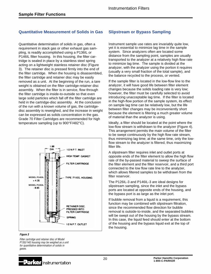
Figure 3
Filter cartridge and retainer disc of ModelP13G/14G housing may be weighed as a unitfor quantitative determination of solids ingases.
Quantitative Measurement of Solids in Gas
Quantitative determination of solids in gas, often arequirement in stack gas or other exhaust gas sam-pling, is readily accomplished using a P136IL orP146IL filter housing. In this housing, the filter car-tridge is sealed in place by a stainless steel springacting on a lightweight stainless retainer disc (Figure3). The retainer disc is pressed firmly into the end ofthe filter cartridge. When the housing is disassembled,the filter cartridge and retainer disc may be easilyremoved as a unit. At the beginning of the run, a tareweight is obtained on the filter cartridge-retainer discassembly. When the filter is in service, flow throughthe filter cartridge is inside-to-outside so that evenlarge solid particles which fall off the filter cartridge areheld in the cartridge-disc assembly. At the conclusionof the run with a known volume of gas, the cartridge-disc assembly is reweighed, and the increase in weightcan be expressed as solids concentration in the gas.Grade 70 Filter Cartridges are recommended for hightemperature sampling (up to 900°F/482°C).
Sample Filter Functions
MODEL P14GIL
MODEL P13GIL
Instrumentation Filters
21 Parker Hannifin Corporation1-800-C-PARKER
Quantitative determination of nonvolatile liquidssuspended in a gas may be accomplished by aprocedure similar to the solids determination. In thecase of liquids, the test is designed so that all the liquidentering the filter cartridge during the test periodremains trapped on the fibers; i.e., the sample periodis short enough that the filter cartridge does notbecome saturated and begin to drain liquid.
Any convenient filter housing may be used. The filtercartridge should be Grade 01, to assure quantitativeretention of aerosols, no matter what droplet size.With a known gas flow rate and test duration, theincrease in weight of the filter cartridge will be ameasure of the weight concentration of aerosol in thegas.
Considerable care must be taken to obtain a represen-tative sample of aerosol in gas. If sampling from alarge line, the sample probe should enter the pipe fromabove and if possible, extend into the pipe to avoidpicking up liquid clinging to the wall of the pipe. Thereshould be no valves, reducers, or sharp elbows in thesample line upstream from the filter.
Quantitative Measurement ofLiquids in Gas
Sample Filter Functions
The filtration requirement for ambient air samplers isusually to remove solid particles or liquid dropletswhich could deposit on analyzer optical surfaces orcause other calibration problems. Grade 70 filtercartridges are recommended. For low flow ratepersonal samplers, the compact and lightweight DIF isoften used.
Ambient air sampling systems are often under nega-tive pressure, induced by the sampling pump. If it isnecessary to drain coalesced liquid from the system,the external reservoir is often the most convenientmethod.
Sampling Ambient Air or OtherAtmospheric Pressure Gas

Instrumentation Filters
22 Parker Hannifin Corporation1-800-C-PARKER
Application Notes
Instrumentation Filters
23 Parker Hannifin Corporation1-800-C-PARKER
Application Notes

Instrumentation Filters
24 Parker Hannifin Corporation1-800-C-PARKER
Application Notes
Parker Hannifin CorporationInstrumentation Group Headquarters6035 Parkland Blvd.Cleveland, Ohio 44124-4141Telephone: (216) 896-3000Fax: (216) 896-4000www.parker.com
Bulletin IP-APrinted July 2002
Parker WorldwideSales OfficesContact Parker’s worldwide serviceand distribution network by calling:
Argentina ............................ +54 1 752 4129Australia ............................. +61 2 634 7777Austria ............................ +43 2622 23501 5Belgium .............................. +32 2 762 1800Brazil ................................ +55 11 847 1222Canada ............................. 1-800-272-7537Central & SouthAmerica/Caribbean ........... 1-305-470-8800China .............................. +86 21 6445 9339Chile .................................... +562 623-1216Czech Republic ............ (420) (2) 830 85 22Denmark ............................. +45 43 541133Finland ................................. +358 3 54 100France .............................. +33 4 50 258025Germany ........................... +49 3727 90991Hong Kong ........................ +852 2428 8008Hungary ............................ +36 1 25 22 539India ................................. +91 22 577 1671Italy ....................................... +39 2 451921Japan ............................... +81 45 861 3811Jordan .............................. (962) (6) 810679Korea Choongnam ......... +82 417 583 1410Korea Kyoungnam ......... +82 523 389 0100Korea ................................. +82 2 561 0414Mexico ............................... 1-800-272-7537Netherlands ......................... +31 541 58500New Zealand ...................... +64 9 573 1523Norway .............................. +47 64 86 77 60Poland ............................... +48 22 8634942Singapore .............................. +65 261 5233South Africa ...................... +27 11 3927280Spain ................................... +34 1 6757300Sweden .............................. +46 8 760 2960Switzerland ................... +41 (81) 2 526676Taiwan ........................... +886 2 8787 3780Thailand .............................. +662 693 3304United Arab Emirates ........... +971 2 788587United Kingdom .............. +44 1924 487000USA ................................... 1-800-272-7537
Venezuela .......................... +58 2 238 5422
Note: The (+) sign in front of the countrycode indicates that you may need todial an additional prefix.