instrument control toolbox 2 user's guide - ulisboa simevents, and xpc targetbox are registered...
TRANSCRIPT

Instrument Control Toolbox 2User’s Guide

How to Contact The MathWorks
www.mathworks.com Webcomp.soft-sys.matlab Newsgroupwww.mathworks.com/contact_TS.html Technical Support
[email protected] Product enhancement [email protected] Bug [email protected] Documentation error [email protected] Order status, license renewals, [email protected] Sales, pricing, and general information
508-647-7000 (Phone)
508-647-7001 (Fax)
The MathWorks, Inc.3 Apple Hill DriveNatick, MA 01760-2098For contact information about worldwide offices, see the MathWorks Web site.
Instrument Control Toolbox User’s Guide
© COPYRIGHT 2000–2007 The MathWorks, Inc.The software described in this document is furnished under a license agreement. The software may be usedor copied only under the terms of the license agreement. No part of this manual may be photocopied orreproduced in any form without prior written consent from The MathWorks, Inc.
FEDERAL ACQUISITION: This provision applies to all acquisitions of the Program and Documentationby, for, or through the federal government of the United States. By accepting delivery of the Program orDocumentation, the government hereby agrees that this software or documentation qualifies as commercialcomputer software or commercial computer software documentation as such terms are used or definedin FAR 12.212, DFARS Part 227.72, and DFARS 252.227-7014. Accordingly, the terms and conditions ofthis Agreement and only those rights specified in this Agreement, shall pertain to and govern the use,modification, reproduction, release, performance, display, and disclosure of the Program and Documentationby the federal government (or other entity acquiring for or through the federal government) and shallsupersede any conflicting contractual terms or conditions. If this License fails to meet the government’sneeds or is inconsistent in any respect with federal procurement law, the government agrees to return theProgram and Documentation, unused, to The MathWorks, Inc.
Trademarks
MATLAB, Simulink, Stateflow, Handle Graphics, Real-Time Workshop, SimBiology,SimHydraulics, SimEvents, and xPC TargetBox are registered trademarks and TheMathWorks, the L-shaped membrane logo, Embedded MATLAB, and PolySpace aretrademarks of The MathWorks, Inc.
Other product or brand names are trademarks or registered trademarks of their respectiveholders.
Patents
The MathWorks products are protected by one or more U.S. patents. Please seewww.mathworks.com/patents for more information.

Revision HistoryNovember 2000 First printing New for Version 1.0 (Release 12)June 2001 Second printing Revised for Version 1.1 (Release 12.1)July 2002 Online only Revised for Version 1.2 (Release 13)August 2002 Third printing Revised for Version 1.2June 2004 Online only Revised for Version 2.0 (Release 14)October 2004 Fourth printing Revised for Version 2.1 (Release 14SP1)March 2005 Online only Revised for Version 2.2 (Release 14SP2)June 2005 Fifth printing Minor revision for Version 2.2September 2005 Online only Revised for Version 2.3 (Release 14SP3)March 2006 Online only Revised for Version 2.4 (Release 2006a)September 2006 Online only Revised for Version 2.4.1 (Release 2006b)March 2007 Online only Revised for Version 2.4.2 (Release 2007a)September 2007 Sixth printing Revised for Version 2.5 (Release 2007b)


Contents
Getting Started
1What Is Instrument Control Toolbox? . . . . . . . . . . . . . . . . 1-2
Getting to Know the Instrument Control Toolbox . . . . . . . . 1-2Exploring Instrument Control Toolbox . . . . . . . . . . . . . . . . 1-3Learning About Instrument Control Toolbox . . . . . . . . . . . 1-3Using the Documentation Examples . . . . . . . . . . . . . . . . . . 1-4
Toolbox Components . . . . . . . . . . . . . . . . . . . . . . . . . . . . . . . 1-5Passing Information Between MATLAB and Your
Instrument . . . . . . . . . . . . . . . . . . . . . . . . . . . . . . . . . . . . 1-5M-File Functions . . . . . . . . . . . . . . . . . . . . . . . . . . . . . . . . . . 1-7Interface Driver Adaptor . . . . . . . . . . . . . . . . . . . . . . . . . . . 1-8
Understanding the Toolbox Capabilities . . . . . . . . . . . . . 1-9Overview Help . . . . . . . . . . . . . . . . . . . . . . . . . . . . . . . . . . . . 1-9Documentation Examples . . . . . . . . . . . . . . . . . . . . . . . . . . . 1-9Demos . . . . . . . . . . . . . . . . . . . . . . . . . . . . . . . . . . . . . . . . . . 1-9
Installation Information . . . . . . . . . . . . . . . . . . . . . . . . . . . 1-10Installation Requirements . . . . . . . . . . . . . . . . . . . . . . . . . . 1-10Toolbox Installation . . . . . . . . . . . . . . . . . . . . . . . . . . . . . . . . 1-10Hardware and Driver Installation . . . . . . . . . . . . . . . . . . . . 1-11
Examining Your Hardware Resources . . . . . . . . . . . . . . . 1-12instrhwinfo Function . . . . . . . . . . . . . . . . . . . . . . . . . . . . . . 1-12Test & Measurement Tool . . . . . . . . . . . . . . . . . . . . . . . . . . . 1-16Viewing the IVI Configuration Store . . . . . . . . . . . . . . . . . . 1-18
Communicating with Your Instrument . . . . . . . . . . . . . . 1-21Instrument Control Session Examples . . . . . . . . . . . . . . . . 1-21Example: Communicating with a GPIB Instrument . . . . . 1-21Example: Communicating with a GPIB-VXI Instrument . . 1-22Example: Communicating with a Serial Port
Instrument . . . . . . . . . . . . . . . . . . . . . . . . . . . . . . . . . . . . 1-24
v

Example: Communicating with a GPIB Instrument Using aDevice Object . . . . . . . . . . . . . . . . . . . . . . . . . . . . . . . . . . . 1-25
General Preferences for Instrument Control . . . . . . . . . 1-27Accessing General Preferences . . . . . . . . . . . . . . . . . . . . . . . 1-27MATLAB Instrument Driver Editor . . . . . . . . . . . . . . . . . . 1-28MATLAB Instrument Driver Testing Tool . . . . . . . . . . . . . . 1-28Device Objects . . . . . . . . . . . . . . . . . . . . . . . . . . . . . . . . . . . . 1-29IVI Configuration Store . . . . . . . . . . . . . . . . . . . . . . . . . . . . 1-30
Getting Help . . . . . . . . . . . . . . . . . . . . . . . . . . . . . . . . . . . . . . 1-31instrhelp Function . . . . . . . . . . . . . . . . . . . . . . . . . . . . . . . . . 1-31propinfo Function . . . . . . . . . . . . . . . . . . . . . . . . . . . . . . . . . 1-31Online Support . . . . . . . . . . . . . . . . . . . . . . . . . . . . . . . . . . . 1-33
The Instrument Control Session
2Creating Instrument Objects . . . . . . . . . . . . . . . . . . . . . . . 2-2
Overview . . . . . . . . . . . . . . . . . . . . . . . . . . . . . . . . . . . . . . . . 2-2Interface Objects . . . . . . . . . . . . . . . . . . . . . . . . . . . . . . . . . . 2-2Device Objects . . . . . . . . . . . . . . . . . . . . . . . . . . . . . . . . . . . . 2-3
Connecting to the Instrument . . . . . . . . . . . . . . . . . . . . . . 2-4
Configuring and Returning Properties . . . . . . . . . . . . . . 2-5Configuring Property Names and Property Values . . . . . . . 2-5Returning Property Names and Property Values . . . . . . . . 2-5Property Inspector . . . . . . . . . . . . . . . . . . . . . . . . . . . . . . . . . 2-6
Communicating with Your Instrument . . . . . . . . . . . . . . 2-7Interface Objects and Instrument Commands . . . . . . . . . . 2-7Device Objects and Instrument Drivers . . . . . . . . . . . . . . . 2-7
Disconnecting and Cleaning Up . . . . . . . . . . . . . . . . . . . . . 2-8Disconnecting an Instrument Object . . . . . . . . . . . . . . . . . . 2-8Cleaning Up the MATLAB Environment . . . . . . . . . . . . . . 2-8
vi Contents

Summary . . . . . . . . . . . . . . . . . . . . . . . . . . . . . . . . . . . . . . . . . 2-9Advantages of Using Device Objects . . . . . . . . . . . . . . . . . . 2-9When to Use Interface Objects . . . . . . . . . . . . . . . . . . . . . . . 2-9
Using Interface Objects
3Creating an Interface Object . . . . . . . . . . . . . . . . . . . . . . . 3-2
Object Creation Functions . . . . . . . . . . . . . . . . . . . . . . . . . . 3-2Configuring Properties During Object Creation . . . . . . . . . 3-3Creating an Array of Instrument Objects . . . . . . . . . . . . . . 3-3
Connecting to the Instrument . . . . . . . . . . . . . . . . . . . . . . 3-5
Configuring and Returning Properties . . . . . . . . . . . . . . 3-6Base and Interface-Specific Properties . . . . . . . . . . . . . . . . 3-6Returning Property Names and Property Values . . . . . . . . 3-6Configuring Property Values . . . . . . . . . . . . . . . . . . . . . . . . 3-9Specifying Property Names . . . . . . . . . . . . . . . . . . . . . . . . . 3-10Default Property Values . . . . . . . . . . . . . . . . . . . . . . . . . . . . 3-10Property Inspector . . . . . . . . . . . . . . . . . . . . . . . . . . . . . . . . . 3-11
Writing and Reading Data . . . . . . . . . . . . . . . . . . . . . . . . . . 3-12Before Performing Read/Write Operations . . . . . . . . . . . . . 3-12Writing Data . . . . . . . . . . . . . . . . . . . . . . . . . . . . . . . . . . . . . 3-13Reading Data . . . . . . . . . . . . . . . . . . . . . . . . . . . . . . . . . . . . . 3-19
Disconnecting and Cleaning Up . . . . . . . . . . . . . . . . . . . . . 3-25Disconnecting an Instrument Object . . . . . . . . . . . . . . . . . . 3-25Cleaning Up the MATLAB Environment . . . . . . . . . . . . . . 3-25
Controlling Instruments Using GPIB
4GPIB Overview . . . . . . . . . . . . . . . . . . . . . . . . . . . . . . . . . . . . 4-3
vii

What Is GPIB? . . . . . . . . . . . . . . . . . . . . . . . . . . . . . . . . . . . . 4-3Important GPIB Features . . . . . . . . . . . . . . . . . . . . . . . . . . . 4-4GPIB Lines . . . . . . . . . . . . . . . . . . . . . . . . . . . . . . . . . . . . . . 4-5Status and Event Reporting . . . . . . . . . . . . . . . . . . . . . . . . . 4-10
Creating a GPIB Object . . . . . . . . . . . . . . . . . . . . . . . . . . . . 4-15Using the gpib Function . . . . . . . . . . . . . . . . . . . . . . . . . . . . 4-15GPIB Object Display . . . . . . . . . . . . . . . . . . . . . . . . . . . . . . . 4-16
Configuring the GPIB Address . . . . . . . . . . . . . . . . . . . . . . 4-18
Writing and Reading Data . . . . . . . . . . . . . . . . . . . . . . . . . . 4-19Rules for Completing Write and Read Operations . . . . . . . 4-19Example: Writing and Reading Text Data . . . . . . . . . . . . . 4-20Example: Reading Binary Data . . . . . . . . . . . . . . . . . . . . . . 4-22Example: Parsing Input Data Using scanstr . . . . . . . . . . . 4-24Example: Understanding EOI and EOS . . . . . . . . . . . . . . . 4-25
Events and Callbacks . . . . . . . . . . . . . . . . . . . . . . . . . . . . . . 4-28Example: Introduction to Events and Callbacks . . . . . . . . . 4-28Event Types and Callback Properties . . . . . . . . . . . . . . . . . 4-29Storing Event Information . . . . . . . . . . . . . . . . . . . . . . . . . . 4-30Creating and Executing Callback Functions . . . . . . . . . . . . 4-32Enabling Callback Functions After They Error . . . . . . . . . 4-33Example: Using Events and Callbacks to Read Binary
Data . . . . . . . . . . . . . . . . . . . . . . . . . . . . . . . . . . . . . . . . . . 4-33
Triggers . . . . . . . . . . . . . . . . . . . . . . . . . . . . . . . . . . . . . . . . . . 4-36Using the trigger Function . . . . . . . . . . . . . . . . . . . . . . . . . . 4-36Example: Executing a Trigger . . . . . . . . . . . . . . . . . . . . . . . 4-36
Serial Polls . . . . . . . . . . . . . . . . . . . . . . . . . . . . . . . . . . . . . . . . 4-39Using the spoll Function . . . . . . . . . . . . . . . . . . . . . . . . . . . . 4-39Example: Executing a Serial Poll . . . . . . . . . . . . . . . . . . . . . 4-39
viii Contents

Controlling Instruments Using VISA
5VISA Overview . . . . . . . . . . . . . . . . . . . . . . . . . . . . . . . . . . . . 5-3
What Is VISA? . . . . . . . . . . . . . . . . . . . . . . . . . . . . . . . . . . . . 5-3Interfaces Used with VISA . . . . . . . . . . . . . . . . . . . . . . . . . . 5-3
Working with the GPIB Interface . . . . . . . . . . . . . . . . . . . 5-5Understanding VISA-GPIB . . . . . . . . . . . . . . . . . . . . . . . . . 5-5Creating a VISA-GPIB Object . . . . . . . . . . . . . . . . . . . . . . . 5-5The VISA-GPIB Address . . . . . . . . . . . . . . . . . . . . . . . . . . . . 5-7
Working with the VXI Interface . . . . . . . . . . . . . . . . . . . . . 5-9Understanding VISA-VXI . . . . . . . . . . . . . . . . . . . . . . . . . . 5-9Creating a VISA-VXI Object . . . . . . . . . . . . . . . . . . . . . . . . . 5-10The VISA-VXI Address . . . . . . . . . . . . . . . . . . . . . . . . . . . . . 5-12Register-Based Communication . . . . . . . . . . . . . . . . . . . . . . 5-12
Working with the GPIB-VXI Interface . . . . . . . . . . . . . . . 5-22Understanding VISA_GPIB_VXI . . . . . . . . . . . . . . . . . . . . . 5-22Creating a VISA-GPIB-VXI Object . . . . . . . . . . . . . . . . . . . 5-23The VISA-GPIB-VXI Address . . . . . . . . . . . . . . . . . . . . . . . . 5-25
Working with the Serial Port Interface . . . . . . . . . . . . . . 5-27Understanding the Serial Port . . . . . . . . . . . . . . . . . . . . . . . 5-27Creating a VISA-Serial Object . . . . . . . . . . . . . . . . . . . . . . . 5-27Configuring Communication Settings . . . . . . . . . . . . . . . . . 5-29
Working with the USB Interface . . . . . . . . . . . . . . . . . . . . 5-31Creating a VISA-USB Object . . . . . . . . . . . . . . . . . . . . . . . . 5-31The VISA-USB Address . . . . . . . . . . . . . . . . . . . . . . . . . . . . 5-33
Working with the TCP/IP Interface . . . . . . . . . . . . . . . . . . 5-35Understanding VISA-TCP/IP . . . . . . . . . . . . . . . . . . . . . . . . 5-35Creating a VISA-TCPIP Object . . . . . . . . . . . . . . . . . . . . . . 5-35The VISA-TCPIP Address . . . . . . . . . . . . . . . . . . . . . . . . . . . 5-37
Working with the RSIB Interface . . . . . . . . . . . . . . . . . . . . 5-39Creating a VISA-RSIB Object . . . . . . . . . . . . . . . . . . . . . . . 5-39The VISA-RSIB Address . . . . . . . . . . . . . . . . . . . . . . . . . . . . 5-41
ix

Controlling Instruments Using the Serial Port
6Serial Port Overview . . . . . . . . . . . . . . . . . . . . . . . . . . . . . . . 6-2
What Is Serial Communication? . . . . . . . . . . . . . . . . . . . . . . 6-2The Serial Port Interface Standard . . . . . . . . . . . . . . . . . . . 6-3Supported Platforms . . . . . . . . . . . . . . . . . . . . . . . . . . . . . . . 6-3Connecting Two Devices with a Serial Cable . . . . . . . . . . . 6-3Serial Port Signals and Pin Assignments . . . . . . . . . . . . . . 6-5Serial Data Format . . . . . . . . . . . . . . . . . . . . . . . . . . . . . . . . 6-9Finding Serial Port Information for Your Platform . . . . . . . 6-13
The Serial Port Object . . . . . . . . . . . . . . . . . . . . . . . . . . . . . 6-16Creating a Serial Port Object . . . . . . . . . . . . . . . . . . . . . . . . 6-16The Serial Port Object Display . . . . . . . . . . . . . . . . . . . . . . . 6-17
Configuring Communication Settings . . . . . . . . . . . . . . . 6-19
Writing and Reading Data . . . . . . . . . . . . . . . . . . . . . . . . . . 6-20Asynchronous Write and Read Operations . . . . . . . . . . . . . 6-20Rules for Completing Write and Read Operations . . . . . . . 6-21Example: Writing and Reading Text Data . . . . . . . . . . . . . 6-22
Events and Callbacks . . . . . . . . . . . . . . . . . . . . . . . . . . . . . . 6-25Event Types and Callback Properties . . . . . . . . . . . . . . . . . 6-25Storing Event Information . . . . . . . . . . . . . . . . . . . . . . . . . . 6-26Example: Using Events and Callbacks . . . . . . . . . . . . . . . . 6-28
Using Control Pins . . . . . . . . . . . . . . . . . . . . . . . . . . . . . . . . . 6-30Control Pins . . . . . . . . . . . . . . . . . . . . . . . . . . . . . . . . . . . . . . 6-30Signaling the Presence of Connected Devices . . . . . . . . . . . 6-30Controlling the Flow of Data: Handshaking . . . . . . . . . . . . 6-33
Controlling Instruments Using TCP/IP and UDP
7TCP/IP and UDP Overview . . . . . . . . . . . . . . . . . . . . . . . . . 7-2
x Contents

Creating a TCP/IP Object . . . . . . . . . . . . . . . . . . . . . . . . . . . 7-4TCP/IP Object . . . . . . . . . . . . . . . . . . . . . . . . . . . . . . . . . . . . 7-4TCP/IP Object Display . . . . . . . . . . . . . . . . . . . . . . . . . . . . . 7-5Example: Communicating with a Remote Host . . . . . . . . . 7-6Example: Server Drops the Connection . . . . . . . . . . . . . . . . 7-7
Creating an UDP Object . . . . . . . . . . . . . . . . . . . . . . . . . . . . 7-10UDP Object . . . . . . . . . . . . . . . . . . . . . . . . . . . . . . . . . . . . . . 7-10The UDP Object Display . . . . . . . . . . . . . . . . . . . . . . . . . . . . 7-11Example: Communicating Between Two Hosts . . . . . . . . . 7-12
Writing and Reading Data . . . . . . . . . . . . . . . . . . . . . . . . . . 7-14Rules for Completing Write and Read Operations . . . . . . . 7-14Example: Writing and Reading Data with a TCP/IP
Object . . . . . . . . . . . . . . . . . . . . . . . . . . . . . . . . . . . . . . . . . 7-15Example: Writing and Reading Data with a UDP Object . . 7-18
Events and Callbacks . . . . . . . . . . . . . . . . . . . . . . . . . . . . . . 7-21Event Types and Callback Properties . . . . . . . . . . . . . . . . . 7-21Storing Event Information . . . . . . . . . . . . . . . . . . . . . . . . . . 7-22Example: Using Events and Callbacks . . . . . . . . . . . . . . . . 7-24
Using Device Objects
8Device Objects . . . . . . . . . . . . . . . . . . . . . . . . . . . . . . . . . . . . 8-2
Device Objects: Overview . . . . . . . . . . . . . . . . . . . . . . . . . . . 8-2What Are Device Objects? . . . . . . . . . . . . . . . . . . . . . . . . . . . 8-2Device Objects for MATLAB Instrument Drivers . . . . . . . . 8-3
Creating and Connecting Device Objects . . . . . . . . . . . . 8-5Device Objects for MATLAB Interface Drivers . . . . . . . . . . 8-5Device Objects for VXIplug&play and IVI Drivers . . . . . . . 8-7Connecting the Device Object . . . . . . . . . . . . . . . . . . . . . . . . 8-7
Communicating with Instruments . . . . . . . . . . . . . . . . . . 8-9Configuring Instrument Settings . . . . . . . . . . . . . . . . . . . . . 8-9Calling Device Object Methods . . . . . . . . . . . . . . . . . . . . . . . 8-10
xi

Control Commands . . . . . . . . . . . . . . . . . . . . . . . . . . . . . . . . 8-12
Device Groups . . . . . . . . . . . . . . . . . . . . . . . . . . . . . . . . . . . . . 8-14Working with Group Objects . . . . . . . . . . . . . . . . . . . . . . . . 8-14Example: Using Device Groups to Access Instrument
Data . . . . . . . . . . . . . . . . . . . . . . . . . . . . . . . . . . . . . . . . . . 8-15
Using VXIplug&play Drivers
9Overview . . . . . . . . . . . . . . . . . . . . . . . . . . . . . . . . . . . . . . . . . 9-2
The Instrument Control Toolbox and VXIplug&play Drivers. . . . . . . . . . . . . . . . . . . . . . . . . . . . . . . . . . . . . . . . . . . . . . 9-2
VISA Setup . . . . . . . . . . . . . . . . . . . . . . . . . . . . . . . . . . . . . . 9-2Other Software Requirements . . . . . . . . . . . . . . . . . . . . . . . 9-3
VXIplug&play Drivers . . . . . . . . . . . . . . . . . . . . . . . . . . . . . 9-4Installing VXI plug&play Drivers . . . . . . . . . . . . . . . . . . . . 9-4Creating a MATLAB VXIplug&play Instrument Driver . . 9-5Constructing Device Objects Using a MATLAB
VXIplug&play Instrument Driver . . . . . . . . . . . . . . . . . . 9-8
Using IVI Drivers
10IVI Drivers Overview . . . . . . . . . . . . . . . . . . . . . . . . . . . . . . 10-2
Instrument Control Toolbox and IVI Drivers . . . . . . . . . . . 10-2VISA Setup . . . . . . . . . . . . . . . . . . . . . . . . . . . . . . . . . . . . . . 10-2IVI Shared Components . . . . . . . . . . . . . . . . . . . . . . . . . . . . 10-3IVI Configuration Store Overview . . . . . . . . . . . . . . . . . . . . 10-3
IVI Drivers . . . . . . . . . . . . . . . . . . . . . . . . . . . . . . . . . . . . . . . . 10-4MATLAB IVI Driver . . . . . . . . . . . . . . . . . . . . . . . . . . . . . . . 10-4IVI-C and IVI-COM . . . . . . . . . . . . . . . . . . . . . . . . . . . . . . . . 10-4Installing IVI Drivers . . . . . . . . . . . . . . . . . . . . . . . . . . . . . . 10-5MATLAB IVI Instrument Drivers . . . . . . . . . . . . . . . . . . . . 10-6
xii Contents

Constructing Device Objects Using a MATLAB IVIInstrument Driver . . . . . . . . . . . . . . . . . . . . . . . . . . . . . . 10-9
IVI Configuration Store . . . . . . . . . . . . . . . . . . . . . . . . . . . . 10-11Benefits of an IVI Configuration Store . . . . . . . . . . . . . . . . 10-11Components of an IVI Configuration Store . . . . . . . . . . . . . 10-11Configuring an IVI Configuration Store . . . . . . . . . . . . . . . 10-13
Using Generic Instrument Drivers
11Generic Drivers: Overview . . . . . . . . . . . . . . . . . . . . . . . . . 11-2
Example: Writing a Generic Driver . . . . . . . . . . . . . . . . . . 11-3Creating the Driver and Defining Its Initialization
Behavior . . . . . . . . . . . . . . . . . . . . . . . . . . . . . . . . . . . . . . 11-3Defining Properties . . . . . . . . . . . . . . . . . . . . . . . . . . . . . . . . 11-5Defining Functions . . . . . . . . . . . . . . . . . . . . . . . . . . . . . . . . 11-8
Example: Using a Generic Driver with the Test &Measurement Tool . . . . . . . . . . . . . . . . . . . . . . . . . . . . . . . 11-9Creating and Connecting the Device Object . . . . . . . . . . . . 11-9Accessing Properties . . . . . . . . . . . . . . . . . . . . . . . . . . . . . . . 11-11Using Functions . . . . . . . . . . . . . . . . . . . . . . . . . . . . . . . . . . 11-11
Example: Using a Generic Driver at the CommandLine . . . . . . . . . . . . . . . . . . . . . . . . . . . . . . . . . . . . . . . . . . . . 11-13Creating and Connecting the Device Object . . . . . . . . . . . . 11-13Accessing Properties . . . . . . . . . . . . . . . . . . . . . . . . . . . . . . . 11-14Using Functions . . . . . . . . . . . . . . . . . . . . . . . . . . . . . . . . . . 11-15
Saving and Loading the Session
12Saving and Loading Instrument Objects . . . . . . . . . . . . . 12-2
xiii

Saving Instrument Objects to an M-File . . . . . . . . . . . . . . . 12-2Saving Objects to a MAT-File . . . . . . . . . . . . . . . . . . . . . . . . 12-4
Debugging: Recording Information to Disk . . . . . . . . . . 12-6Using the record Function . . . . . . . . . . . . . . . . . . . . . . . . . . 12-6Example: Introduction to Recording Information . . . . . . . . 12-7Creating Multiple Record Files . . . . . . . . . . . . . . . . . . . . . . 12-7Specifying a File Name . . . . . . . . . . . . . . . . . . . . . . . . . . . . . 12-8Record File Format . . . . . . . . . . . . . . . . . . . . . . . . . . . . . . . . 12-8Example: Recording Information to Disk . . . . . . . . . . . . . . 12-10
Test & Measurement Tool
13Test & Measurement Tool: Overview . . . . . . . . . . . . . . . . 13-2
Instrument Control Toolbox Support . . . . . . . . . . . . . . . . . . 13-2Navigating the Tree . . . . . . . . . . . . . . . . . . . . . . . . . . . . . . . 13-3
Using the Test & Measurement Tool . . . . . . . . . . . . . . . . . 13-4Overview of the Examples . . . . . . . . . . . . . . . . . . . . . . . . . . 13-4Hardware . . . . . . . . . . . . . . . . . . . . . . . . . . . . . . . . . . . . . . . . 13-4Instrument Objects . . . . . . . . . . . . . . . . . . . . . . . . . . . . . . . . 13-12Instrument Drivers . . . . . . . . . . . . . . . . . . . . . . . . . . . . . . . . 13-16
Using the Instrument Driver Editor
14MATLAB Instrument Driver Editor: Overview . . . . . . . 14-2
What Is a MATLAB Instrument Driver? . . . . . . . . . . . . . . . 14-2How Does a MATLAB Instrument Driver Work? . . . . . . . . 14-3Why Use a MATLAB Instrument Driver? . . . . . . . . . . . . . . 14-3
Creating MATLAB Instrument Drivers . . . . . . . . . . . . . . 14-5Driver Components . . . . . . . . . . . . . . . . . . . . . . . . . . . . . . . . 14-5MATLAB Instrument Driver Editor Features . . . . . . . . . . . 14-6Saving MATLAB Instrument Drivers . . . . . . . . . . . . . . . . . 14-6
xiv Contents

Driver Summary and Control Commands . . . . . . . . . . . . . . 14-6Initialization and Cleanup . . . . . . . . . . . . . . . . . . . . . . . . . . 14-10
Properties . . . . . . . . . . . . . . . . . . . . . . . . . . . . . . . . . . . . . . . . 14-18Properties: Overview . . . . . . . . . . . . . . . . . . . . . . . . . . . . . . 14-18Property Components . . . . . . . . . . . . . . . . . . . . . . . . . . . . . . 14-18Examples of Properties . . . . . . . . . . . . . . . . . . . . . . . . . . . . . 14-21
Functions . . . . . . . . . . . . . . . . . . . . . . . . . . . . . . . . . . . . . . . . . 14-34Understanding Functions . . . . . . . . . . . . . . . . . . . . . . . . . . . 14-34Function Components . . . . . . . . . . . . . . . . . . . . . . . . . . . . . . 14-34Examples of Functions . . . . . . . . . . . . . . . . . . . . . . . . . . . . . 14-35
Groups . . . . . . . . . . . . . . . . . . . . . . . . . . . . . . . . . . . . . . . . . . . 14-46Group Components . . . . . . . . . . . . . . . . . . . . . . . . . . . . . . . . 14-46Examples of Groups . . . . . . . . . . . . . . . . . . . . . . . . . . . . . . . 14-47
Using Existing Drivers . . . . . . . . . . . . . . . . . . . . . . . . . . . . . 14-65Modifying MATLAB Instrument Drivers . . . . . . . . . . . . . . 14-65Importing VXIplug&play and IVI Drivers . . . . . . . . . . . . . 14-66
Using the Instrument Driver Testing Tool
15Instrument Driver Testing Tool: Overview . . . . . . . . . . . 15-2
Functionality . . . . . . . . . . . . . . . . . . . . . . . . . . . . . . . . . . . . . 15-2Drivers . . . . . . . . . . . . . . . . . . . . . . . . . . . . . . . . . . . . . . . . . . 15-2Test Structure . . . . . . . . . . . . . . . . . . . . . . . . . . . . . . . . . . . . 15-3Starting . . . . . . . . . . . . . . . . . . . . . . . . . . . . . . . . . . . . . . . . . 15-3Example . . . . . . . . . . . . . . . . . . . . . . . . . . . . . . . . . . . . . . . . . 15-4
Setting Up Your Test . . . . . . . . . . . . . . . . . . . . . . . . . . . . . . . 15-5Test File . . . . . . . . . . . . . . . . . . . . . . . . . . . . . . . . . . . . . . . . . 15-5Providing a Name and Description . . . . . . . . . . . . . . . . . . . 15-5Specifying the Driver . . . . . . . . . . . . . . . . . . . . . . . . . . . . . . 15-5Specifying an Interface . . . . . . . . . . . . . . . . . . . . . . . . . . . . . 15-5Setting Test Preferences . . . . . . . . . . . . . . . . . . . . . . . . . . . . 15-6Example: Setting Up a Driver Test . . . . . . . . . . . . . . . . . . . 15-7
xv

Defining Test Steps . . . . . . . . . . . . . . . . . . . . . . . . . . . . . . . . 15-11Test Step: Set Property . . . . . . . . . . . . . . . . . . . . . . . . . . . . . 15-11Test Step: Get Property . . . . . . . . . . . . . . . . . . . . . . . . . . . . 15-15Test Step: Properties Sweep . . . . . . . . . . . . . . . . . . . . . . . . . 15-17Test Step: Function . . . . . . . . . . . . . . . . . . . . . . . . . . . . . . . . 15-21
Saving Your Test . . . . . . . . . . . . . . . . . . . . . . . . . . . . . . . . . . . 15-25Saving the Test as M-Code . . . . . . . . . . . . . . . . . . . . . . . . . . 15-25Saving the Test as a Driver Function . . . . . . . . . . . . . . . . . 15-25
Testing and Results . . . . . . . . . . . . . . . . . . . . . . . . . . . . . . . . 15-28Running All Steps . . . . . . . . . . . . . . . . . . . . . . . . . . . . . . . . . 15-28Partial Testing . . . . . . . . . . . . . . . . . . . . . . . . . . . . . . . . . . . . 15-30Exporting Results . . . . . . . . . . . . . . . . . . . . . . . . . . . . . . . . . 15-30Saving Results . . . . . . . . . . . . . . . . . . . . . . . . . . . . . . . . . . . . 15-31
Using the Instrument Control Toolbox BlockLibrary
16Overview . . . . . . . . . . . . . . . . . . . . . . . . . . . . . . . . . . . . . . . . . 16-2
Opening the Instrument Control Block Library . . . . . . 16-3Using the instrumentlib Command from MATLAB . . . . . . 16-3Using the Simulink Library Browser . . . . . . . . . . . . . . . . . . 16-4
Building Simulink Models to Send and Receive Data . . 16-6Example: Sending and Receiving Data Through a Serial
Port Loopback . . . . . . . . . . . . . . . . . . . . . . . . . . . . . . . . . . 16-6Example: Sending and Receiving Data Via a TCP/IP
Network . . . . . . . . . . . . . . . . . . . . . . . . . . . . . . . . . . . . . . . 16-16
xvi Contents

Functions — By Category
17Instrument Object Creation . . . . . . . . . . . . . . . . . . . . . . . . 17-2
Interface Object . . . . . . . . . . . . . . . . . . . . . . . . . . . . . . . . . . . 17-2Device Object . . . . . . . . . . . . . . . . . . . . . . . . . . . . . . . . . . . . . 17-2
State Change . . . . . . . . . . . . . . . . . . . . . . . . . . . . . . . . . . . . . . 17-2Interface Object . . . . . . . . . . . . . . . . . . . . . . . . . . . . . . . . . . . 17-3Device Object . . . . . . . . . . . . . . . . . . . . . . . . . . . . . . . . . . . . . 17-3
Property Display and Configuration . . . . . . . . . . . . . . . . 17-3
Reading Data . . . . . . . . . . . . . . . . . . . . . . . . . . . . . . . . . . . . . . 17-3
Writing Data . . . . . . . . . . . . . . . . . . . . . . . . . . . . . . . . . . . . . . 17-4
Information and Help . . . . . . . . . . . . . . . . . . . . . . . . . . . . . . 17-5
Graphical Tools . . . . . . . . . . . . . . . . . . . . . . . . . . . . . . . . . . . . 17-5Interface Object . . . . . . . . . . . . . . . . . . . . . . . . . . . . . . . . . . . 17-5Device Object . . . . . . . . . . . . . . . . . . . . . . . . . . . . . . . . . . . . . 17-5
General Purpose . . . . . . . . . . . . . . . . . . . . . . . . . . . . . . . . . . . 17-6
Interface Objects . . . . . . . . . . . . . . . . . . . . . . . . . . . . . . . . . . 17-7GPIB . . . . . . . . . . . . . . . . . . . . . . . . . . . . . . . . . . . . . . . . . . . 17-7Serial Port . . . . . . . . . . . . . . . . . . . . . . . . . . . . . . . . . . . . . . . 17-8TCP/IP . . . . . . . . . . . . . . . . . . . . . . . . . . . . . . . . . . . . . . . . . . 17-8UDP . . . . . . . . . . . . . . . . . . . . . . . . . . . . . . . . . . . . . . . . . . . . 17-8VISA-GPIB . . . . . . . . . . . . . . . . . . . . . . . . . . . . . . . . . . . . . . 17-8VISA-GPIB-VXI . . . . . . . . . . . . . . . . . . . . . . . . . . . . . . . . . . . 17-8VISA-Serial . . . . . . . . . . . . . . . . . . . . . . . . . . . . . . . . . . . . . . 17-9VISA-VXI . . . . . . . . . . . . . . . . . . . . . . . . . . . . . . . . . . . . . . . . 17-9
Device Objects . . . . . . . . . . . . . . . . . . . . . . . . . . . . . . . . . . . . 17-10
IVI Configuration Store Objects . . . . . . . . . . . . . . . . . . . . . 17-10
xvii

Functions — Alphabetical List
18
Properties — By Category
19Interface Object Base Properties . . . . . . . . . . . . . . . . . . . . 19-2
Writing Data . . . . . . . . . . . . . . . . . . . . . . . . . . . . . . . . . . . . . 19-2Reading Data . . . . . . . . . . . . . . . . . . . . . . . . . . . . . . . . . . . . . 19-2Recording Data . . . . . . . . . . . . . . . . . . . . . . . . . . . . . . . . . . . 19-3Callbacks . . . . . . . . . . . . . . . . . . . . . . . . . . . . . . . . . . . . . . . . 19-3General Purpose . . . . . . . . . . . . . . . . . . . . . . . . . . . . . . . . . . 19-4
Interface-Specific Properties . . . . . . . . . . . . . . . . . . . . . . . 19-5GPIB . . . . . . . . . . . . . . . . . . . . . . . . . . . . . . . . . . . . . . . . . . . 19-5Serial Port . . . . . . . . . . . . . . . . . . . . . . . . . . . . . . . . . . . . . . . 19-6TCPIP . . . . . . . . . . . . . . . . . . . . . . . . . . . . . . . . . . . . . . . . . . 19-7UDP . . . . . . . . . . . . . . . . . . . . . . . . . . . . . . . . . . . . . . . . . . . . 19-7VISA-GPIB . . . . . . . . . . . . . . . . . . . . . . . . . . . . . . . . . . . . . . 19-8VISA-GPIB-VXI . . . . . . . . . . . . . . . . . . . . . . . . . . . . . . . . . . . 19-8VISA-RSIB . . . . . . . . . . . . . . . . . . . . . . . . . . . . . . . . . . . . . . . 19-9VISA-Serial . . . . . . . . . . . . . . . . . . . . . . . . . . . . . . . . . . . . . . 19-10VISA-TCPIP . . . . . . . . . . . . . . . . . . . . . . . . . . . . . . . . . . . . . 19-10VISA-USB . . . . . . . . . . . . . . . . . . . . . . . . . . . . . . . . . . . . . . . 19-11VISA-VXI . . . . . . . . . . . . . . . . . . . . . . . . . . . . . . . . . . . . . . . . 19-11
Device Object Base Properties . . . . . . . . . . . . . . . . . . . . . . 19-13
IVI Configuration Store Object Properties . . . . . . . . . . . 19-14
xviii Contents

Properties — Alphabetical List
20
Blocks — Alphabetical List
21
Vendor Driver Requirements and Limitations
ADriver Requirements . . . . . . . . . . . . . . . . . . . . . . . . . . . . . . A-2
GPIB Driver Limitations by Vendor . . . . . . . . . . . . . . . . . A-3Advantech . . . . . . . . . . . . . . . . . . . . . . . . . . . . . . . . . . . . . . . A-3Agilent Technologies . . . . . . . . . . . . . . . . . . . . . . . . . . . . . . . A-3Capital Equipment Corporation . . . . . . . . . . . . . . . . . . . . . . A-4ICS Electronics . . . . . . . . . . . . . . . . . . . . . . . . . . . . . . . . . . . A-4IOTech . . . . . . . . . . . . . . . . . . . . . . . . . . . . . . . . . . . . . . . . . . A-5Keithley . . . . . . . . . . . . . . . . . . . . . . . . . . . . . . . . . . . . . . . . . A-5Measurement Computing Corporation . . . . . . . . . . . . . . . . A-6
VISA Driver Limitations . . . . . . . . . . . . . . . . . . . . . . . . . . . A-7Agilent Technologies . . . . . . . . . . . . . . . . . . . . . . . . . . . . . . . A-7National Instruments . . . . . . . . . . . . . . . . . . . . . . . . . . . . . . A-7
Bibliography
B
Index
xix

xx Contents

1
Getting Started
What Is Instrument Control Toolbox?(p. 1-2)
The toolbox and the kinds of tasksit can perform
Toolbox Components (p. 1-5) The M-files and interface driveradaptors that compose the toolbox
Understanding the ToolboxCapabilities (p. 1-9)
Resources to help you understandthe toolbox capabilities includingdemos and documentation examples
Installation Information (p. 1-10) How to determine whether thetoolbox is installed on your system
Examining Your HardwareResources (p. 1-12)
Return hardware-relatedinformation visible to the toolboxincluding the installed adaptors andthe syntax for creating instrumentobjects.
Communicating with YourInstrument (p. 1-21)
Examples that show you how tocommunicate with instruments thatsupport the GPIB, GPIB-VXI, andserial port interfaces
General Preferences for InstrumentControl (p. 1-27)
MATLAB preferences related toInstrument Control Toolbox
Getting Help (p. 1-31) Getting help using the Help browser,M-file help, and other methods

1 Getting Started
What Is Instrument Control Toolbox?
In this section...
“Getting to Know the Instrument Control Toolbox” on page 1-2
“Exploring Instrument Control Toolbox” on page 1-3
“Learning About Instrument Control Toolbox” on page 1-3
“Using the Documentation Examples” on page 1-4
Getting to Know the Instrument Control ToolboxInstrument Control Toolbox is a collection of M-file functions built on theMATLAB® technical computing environment. The toolbox provides you withthese features:
• A framework for communicating with instruments that support the GPIBinterface (IEEE-488), the VISA standard, and the TCP/IP and UDPprotocols. Note that the toolbox extends the basic serial port featuresincluded with MATLAB.
• Support for IVI, VXIplug&play, and MATLAB instrument drivers.
• Functions for transferring data between MATLAB and your instrument:
- The data can be binary (numerical) or text.
- The transfer can be synchronous and block the MATLAB command line,or asynchronous and allow access to the MATLAB command line.
• Event-based communication.
• Functions for recording data and event information to a text file.
• Tools that facilitate instrument control in an easy-to-use graphicalenvironment.
The MathWorks provides several related products that are especially relevantto the kinds of tasks you can perform with Instrument Control Toolbox. Formore information about any of these products, see
http://www.mathworks.com/products/instrument/related.jsp.
1-2

What Is Instrument Control Toolbox?
Exploring Instrument Control ToolboxFor a list of the toolbox functions, type
help instrument
For the code of a function, type
type function_name
For help for any function, type
instrhelp function_name
You can change the way any toolbox function works by copying and renamingthe M-file, then modifying your copy. You can also extend the toolbox byadding your own M-files, or by using it in combination with other productssuch as MATLAB Report Generator or Data Acquisition Toolbox.
To use Instrument Control Toolbox, you should you should be familiar withthe:
• Basic features of MATLAB.
• Appropriate commands used to communicate with your instrument.These commands might use the SCPI language or they might be methodsassociated with an IVI, VXIplug&play, or MATLAB instrument driver.
• Features of the interface associated with your instrument.
Learning About Instrument Control ToolboxStart with this chapter, which describes how to examine your hardwareresources, how to communicate with your instrument, how to get onlinehelp, and so on. Then read Chapter 2, “The Instrument Control Session”,which provides a framework for constructing instrument control applications.Depending on the interface used by your instrument, you might then wantto read the appropriate interface-specific chapter.
If you want detailed information about a specific function, refer to Functions— Alphabetical List. If you want detailed information about a specificproperty, refer to Properties — Alphabetical List .
1-3

1 Getting Started
Using the Documentation ExamplesThe examples in this guide use specific instruments such as a TektronixTDS 210 two-channel oscilloscope or an Agilent 33120A function generator.Additionally, the GPIB examples use a National Instruments GPIB controllerand the serial port examples use the COM1 serial port. The string commandswritten to these instruments are often unique to the vendor, and the addressinformation such as the board index or primary address associated with thehardware reflects a specific configuration.
These documentation examples are collected in the example index, which isavailable through the Help browser. You should modify the examples to workwith your specific hardware configuration.
1-4

Toolbox Components
Toolbox Components
In this section...
“Passing Information Between MATLAB and Your Instrument” on page 1-5
“M-File Functions” on page 1-7
“Interface Driver Adaptor” on page 1-8
Passing Information Between MATLAB and YourInstrumentInstrument Control Toolbox consists of two distinct components: M-filefunctions and interface driver adaptors. These components allow you topass information between MATLAB and your instrument. For example,the following diagram shows how information passes from MATLAB to aninstrument via the GPIB driver and the GPIB controller.
1-5

1 Getting Started
This diagram illustrates how information flows from component to component.Information consists of
• Property values
You define the behavior of your instrument control application byconfiguring property values. In general, you can think of a property as a
1-6

Toolbox Components
characteristic of the toolbox or of the instrument that can be configured tosuit your needs.
• Data
You can write data to the instrument and read data from the instrument.Data can be binary (numerical) or formatted as text. Writing text ofteninvolves writing string commands that change hardware settings, orprepare the instrument to return data or status information, while writingbinary data involves writing numerical values such as calibration orwaveform data.
• Events
An event occurs after a condition is met and might result in one or morecallbacks. Events can be generated only after you configure the associatedproperties. For example, you can use events to analyze data after a certainnumber of bytes are read from the instrument, or display a message to theMATLAB command line after an error occurs.
M-File FunctionsTo perform any task within your instrument control application, you mustcall M-file functions from the MATLAB environment. Among other things,these functions allow you to
• Create instrument objects, which provide a gateway to your instrument’scapabilities and allow you to control the behavior of your application.
• Connect the object to the instrument.
• Configure property values.
• Write data to the instrument, and read data from the instrument.
• Examine your hardware resources and evaluate your application status.
For a listing of all Instrument Control Toolbox functions, refer to Functions —Alphabetical List . You can also display the toolbox functions by typing
help instrument
1-7

1 Getting Started
Interface Driver AdaptorThe interface driver adaptor (or just adaptor) is the link between the toolboxand the interface driver. The adaptor’s main purpose is to pass informationbetween MATLAB and the interface driver. Interface drivers are provided byyour instrument vendor. For example, if you are communicating with aninstrument using a National Instruments GPIB controller, then an interfacedriver such as NI-488.2 must be installed on your platform. Note thatinterface drivers are not installed as part of Instrument Control Toolbox.
Instrument Control Toolbox provides adaptors for the GPIB interface and theVISA standard. The serial port, TCP/IP, and UDP interfaces do not requirean adaptor.
Supported Interfaces and Adaptor Names
Interface Adaptor Name
GPIB advantech, agilent, cec, contec, ics, iotech,keithley, mcc, ni
Serial port N/A
TCP/IP N/A
UDP N/A
VISA standard agilent, ni, tek
As described in “Examining Your Hardware Resources” on page 1-12, youcan list the supported interfaces and adaptor names with the instrhwinfofunction. For a list of vendor driver requirements and limitations, refer toAppendix A, “Vendor Driver Requirements and Limitations”.
1-8

Understanding the Toolbox Capabilities
Understanding the Toolbox Capabilities
In this section...
“Overview Help” on page 1-9
“Documentation Examples” on page 1-9
“Demos” on page 1-9
Overview HelpThe overview help lists the toolbox functions grouped by usage. You candisplay this information by typing
help instrument
For the code for any function, type
type function_name
Documentation ExamplesThis guide provides detailed examples that show you how to communicatewith all supported interface types. These examples are collected in theexample index, which is available through the Help browser.
The examples use specific peripheral instruments, GPIB controllers, stringcommands, address information, and so on. If your instrument acceptsdifferent string commands, or if your hardware is configured to use differentaddress information, you should modify the examples accordingly.
DemosThe toolbox includes a large collection of tutorial demos, which you can accessthrough the Help browser Demos pane. Use the following command to openthe Help browser to the toolbox demos:
demo toolbox 'Instrument Control'
You do not need an instrument connected to your computer to use tutorials asthey use prerecorded data.
1-9

1 Getting Started
Installation Information
In this section...
“Installation Requirements” on page 1-10
“Toolbox Installation” on page 1-10
“Hardware and Driver Installation” on page 1-11
Installation RequirementsTo communicate with your instrument from the MATLAB environment, youmust install these components:
• MATLAB 7
• Instrument Control Toolbox
Additionally, you might need to install hardware such as a GPIB controllerand vendor-specific software such as drivers, support libraries, and so on. Fora complete list of all supported vendors, refer to “Interface Driver Adaptor”on page 1-8.
Toolbox InstallationTo determine if Instrument Control Toolbox is installed on your system, type
ver
at the MATLAB prompt. MATLAB displays information about the version ofMATLAB you are running, including a list of installed add-on products andtheir version numbers. Check the list to see if Instrument Control Toolboxappears.
For information about installing the toolbox, refer to the installationdocumentation for your platform. If you experience installation difficulties,look for the installation and license information at the MathWorks Web site(http://www.mathworks.com/support).
1-10

Installation Information
Hardware and Driver InstallationInstallation of hardware devices such as GPIB controllers, instrument drivers,support libraries, and so on is described in the documentation provided by theinstrument vendor. Many vendors provide the latest drivers through theirWeb site. For a list of vendor driver requirements and limitations, refer toAppendix A, “Vendor Driver Requirements and Limitations”.
Note You must install all necessary device-specific software provided by theinstrument vendor in addition to Instrument Control Toolbox.
1-11

1 Getting Started
Examining Your Hardware Resources
In this section...
“instrhwinfo Function” on page 1-12
“Test & Measurement Tool” on page 1-16
“Viewing the IVI Configuration Store” on page 1-18
instrhwinfo FunctionYou can examine the hardware-related resources visible to the toolbox withthe instrhwinfo function. The specific information returned by instrhwinfodepends on the supplied arguments, and is divided into these categories:
• “General Toolbox Information” on page 1-12
• “Interface Information” on page 1-13
• “Adaptor Information” on page 1-13
• “Instrument Object Information” on page 1-15
• “Installed Driver Information” on page 1-16
General Toolbox InformationFor general information about Instrument Control Toolbox, type:
instrhwinfo
MATLABVersion: '7.0 (R14)'SupportedInterfaces: {'gpib' 'serial' 'visa' 'tcpip' 'udp'}
SupportedDrivers: {'matlab' 'vxipnp' 'ivi'}ToolboxName: 'Instrument Control Toolbox'
ToolboxVersion: '2.0 (R14)'
The SupportedInterfaces and SupportedDrivers fields list the interfacesand drivers supported by the toolbox, and not necessarily those installedon your computer.
1-12
Examining Your Hardware Resources
Interface InformationTo display information about a specific interface, you supply the interfacename as an argument to instrhwinfo. The interface name can be gpib,serial, tcpip, udp, or visa.
For the GPIB and VISA interfaces, the information includes installedadaptors. For the serial port interface, the information includes the availableports. For the TCP/IP and UDP interfaces, the information includes the localhost address. For example, to display the GPIB interface information:
out = instrhwinfo('gpib')out =
InstalledAdaptors: {'mcc' 'ni'}JarFileVersion: 'Version 2.0 (R14)'
The InstalledAdaptors field indicates that the Measurement ComputingCorporation and National Instruments drivers are installed. Therefore,you can communicate with instruments using GPIB controllers from thesevendors.
Adaptor InformationTo display information about a specific installed adaptor, you supply theinterface name and the adaptor name as arguments to instrhwinfo.
InterfaceName
Adaptor Name
gpib advantech, agilent, cec, contec, ics, iotech, keithley,mcc, ni
visa agilent, ni, tek
The returned information describes the adaptor, the vendor driver, and theobject constructors. For example, to display information for the NationalInstruments GPIB adaptor,
ghwinfo = instrhwinfo('gpib','ni')
ghwinfo =
1-13

1 Getting Started
AdaptorDllName: [1x82 char]AdaptorDllVersion: 'Version 2.0 (R14)'
AdaptorName: 'NI'InstalledBoardIds: 0
ObjectConstructorName: {'gpib('ni', 0, 2);'}VendorDllName: 'gpib-32.dll'
VendorDriverDescription: 'NI-488'
The ObjectConstructorName field provides the syntax for creating a GPIBobject for the National Instruments adaptor. In this example, the GPIBcontroller has board index 0 and the instrument has primary address 2.
g = gpib('ni',0,2);
To display information for the Tektronix VISA adaptor,
vhwinfo = instrhwinfo('visa','tek')vhwinfo =
AdaptorDllName: [1x83 char]AdaptorDllVersion: 'Version 2.0 (R14 Beta 1)'
AdaptorName: 'TEK'AvailableChassis: []
AvailableSerialPorts: {2x1 cell}InstalledBoardIds: 0
ObjectConstructorName: {3x1 cell}SerialPorts: {2x1 cell}
VendorDllName: 'visa32.dll'VendorDriverDescription: 'Tektronix VISA Driver'
VendorDriverVersion: 2.0500
The available VISA object constructor names are shown below.
vhwinfo.ObjectConstructorNameans =
'visa('tek', 'ASRL1::INSTR');''visa('tek', 'ASRL2::INSTR');''visa('tek', 'GPIB0::1::INSTR');'
1-14

Examining Your Hardware Resources
The ObjectConstructorName field provides the syntax for creating a VISAobject for the GPIB and serial port interfaces. In this example, the GPIBcontroller has board index 0 and the instrument has primary address 1.
vg = visa('tek','GPIB0::1::INSTR');
Instrument Object InformationTo display information about a specific instrument object, you supply theobject as an argument to instrhwinfo. For example, to display informationfor the GPIB object created in the (“Adaptor Information” on page 1-13), type:
ghwinfo = instrhwinfo(g)ghwinfo =
AdaptorDllName: [1x82 char]AdaptorDllVersion: 'Version 2.0 (R14)'
AdaptorName: 'NI'VendorDllName: 'gpib-32.dll'
VendorDriverDescription: 'NI-488'
To display information for the VISA-GPIB object created in the (“AdaptorInformation” on page 1-13), type:
vghwinfo = instrhwinfo(vg)vghwinfo =
AdaptorDllName: [1x83 char]AdaptorDllVersion: 'Version 2.0 (R14)'
AdaptorName: 'TEK'VendorDllName: 'visa32.dll'
VendorDriverDescription: 'Tektronix VISA Driver'VendorDriverVersion: 2.0500
Alternatively, you can return hardware information via the Workspacebrowser by right-clicking an instrument object, and selecting DisplayHardware Info from the context menu.
1-15

1 Getting Started
Installed Driver InformationTo display information about a supported driver type, you supply the drivertype as an argument to instrhwinfo. For example, to display information forthe IVI configuration, type:
instrhwinfo('ivi')
ans =
LogicalNames: {'MyIviCLogical' 'MyScope' 'TekScope'}
ProgramIDs: {'TekScope.TekScope'}
Modules: {'ag3325b'}
ConfigurationServerVersion: '1.3.1.0'
MasterConfigurationStore: 'D:\Apps\IVI\Data\IviConfigurationStore.xml'
IVIRootPath: 'D:\Apps\IVI\'
To display information about a specific driver or resource, you supply thedriver name in addition to the type as an argument to instrhwinfo. Forexample, to display information about the ag3325b VXIplug&play driver:
instrhwinfo('vxipnp', 'ag3325b')ans =
Manufacturer: 'Agilent Technologies'Model: 'Agilent 3325B Synthesizer/Func. Gen.'
DriverVersion: '4.1'DriverDllName: 'C:\VXIPNP\WINNT\bin\ag3325b_32.dll'
Test & Measurement ToolYou can use the Test & Measurement Tool (tmtool) to manage the resourcesof your instrument control session. You can use this tool to:
• Search for installed adaptors.
• Examine available hardware.
• Examine installed drivers.
• Examine instrument objects.
To open the Test & Measurement Tool, type:
tmtool
1-16
Examining Your Hardware Resources
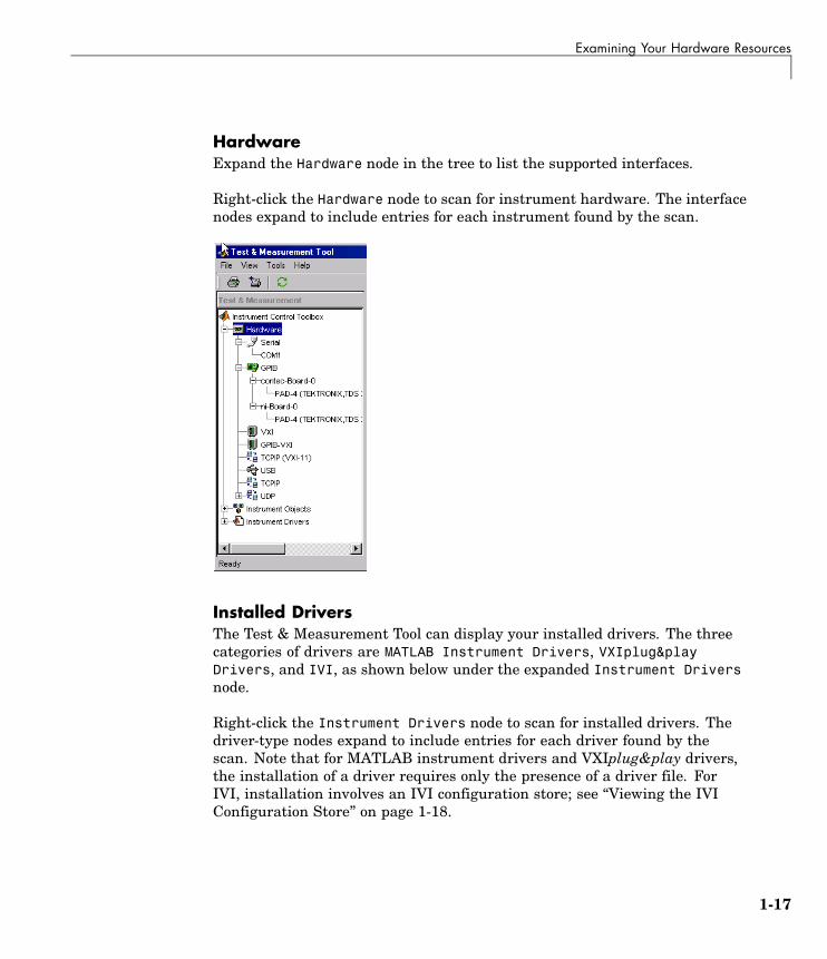
HardwareExpand the Hardware node in the tree to list the supported interfaces.
Right-click the Hardware node to scan for instrument hardware. The interfacenodes expand to include entries for each instrument found by the scan.
Installed DriversThe Test & Measurement Tool can display your installed drivers. The threecategories of drivers are MATLAB Instrument Drivers, VXIplug&playDrivers, and IVI, as shown below under the expanded Instrument Driversnode.
Right-click the Instrument Drivers node to scan for installed drivers. Thedriver-type nodes expand to include entries for each driver found by thescan. Note that for MATLAB instrument drivers and VXIplug&play drivers,the installation of a driver requires only the presence of a driver file. ForIVI, installation involves an IVI configuration store; see “Viewing the IVIConfiguration Store” on page 1-18.
1-17

1 Getting Started
The Test & Measurement Tool GUI includes embedded help. For furtherdetails about the Test & Measurement Tool and its capabilities, see Chapter13, “Test & Measurement Tool”.
Viewing the IVI Configuration StoreAn IVI configuration store greatly enhances instrument interchangeability byproviding the means to configure the relationship between drivers and I/Ointerface references outside of the application. For details of the componentsof an IVI configuration store, see “IVI Configuration Store” on page 10-11.
Command-Line ConfigurationYou can use command-line functions to examine and configure your IVIconfiguration store. To see what IVI configuration store elements areavailable, use instrhwinfo to identify the existing logical names.
instrhwinfo('ivi')ans =
LogicalNames: {'MainScope', 'FuncGen'}ProgramIDs: {'TekScope.TekScope','Agilent33250'}
Modules: {'ag3325b', 'hpe363xa'}ConfigurationServerVersion: '1.3.1.0'
1-18

Examining Your Hardware Resources
MasterConfigurationStore: 'C:\Program Files\IVI\Data\IviConfigurationStore.xml'
IVIRootPath: 'C:\Program Files\IVI\'
Use instrhwinfo with a logical name as an argument to see the details ofthat logical name’s configuration.
instrhwinfo('ivi','MainScope')ans =
DriverSession: 'TekScope.DriverSession'HardwareAsset: 'TekScope.Hardware'
SoftwareModule: 'TekScope.Software'IOResourceDescriptor: 'GPIB0::13::INSTR'
SupportedInstrumentModels: 'TekScope 5000, 6000 and 7000 series'ModuleDescription: 'TekScope software module desc'
ModuleLocation: ''
You create and configure elements in the IVI configuration store by using theIVI configuration store object functions add, commit, remove, and update. Forfurther details, see the reference pages for these functions.
Using the Test & Measurement ToolYou can use the Test & Measurement Tool to examine or configure your IVIconfiguration store. To open the tool, type:
tmtool
Expand the Instrument Drivers node and click IVI.
1-19
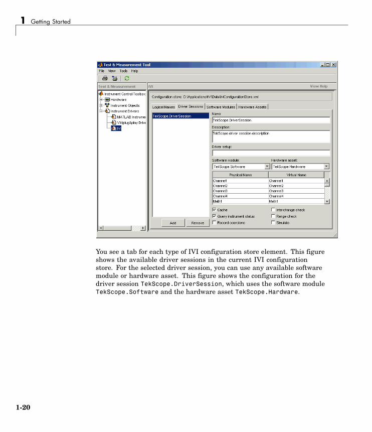
1 Getting Started
You see a tab for each type of IVI configuration store element. This figureshows the available driver sessions in the current IVI configurationstore. For the selected driver session, you can use any available softwaremodule or hardware asset. This figure shows the configuration for thedriver session TekScope.DriverSession, which uses the software moduleTekScope.Software and the hardware asset TekScope.Hardware.
1-20
Communicating with Your Instrument
Communicating with Your Instrument
In this section...
“Instrument Control Session Examples” on page 1-21
“Example: Communicating with a GPIB Instrument” on page 1-21
“Example: Communicating with a GPIB-VXI Instrument” on page 1-22
“Example: Communicating with a Serial Port Instrument” on page 1-24
“Example: Communicating with a GPIB Instrument Using a Device Object”on page 1-25
Instrument Control Session ExamplesEach example illustrates a typical instrument control session. Theinstrument control session comprises all the steps you are likely to take whencommunicating with a supported instrument. You should keep these steps inmind when constructing your own instrument control applications.
The examples also use specific instrument addresses, SCPI commands, and soon. If your instrument requires different parameters, or if it does not supportthe SCPI language, you should modify the examples accordingly.
If you want detailed information about any functions that are used, referto Functions — By Category. If you want detailed information about anyproperties that are used, refer to Properties — By Category.
Example: Communicating with a GPIB InstrumentThis example illustrates how to communicate with a GPIB instrument. TheGPIB controller is a National Instruments AT-GPIB card. The instrumentis an Agilent 33120A Function Generator, which is generating a 2 voltpeak-to-peak signal.
You should modify this example to suit your specific instrument controlapplication needs. If you want detailed information about communicatingwith an instrument via GPIB, refer to Chapter 4, “Controlling InstrumentsUsing GPIB”.
1-21

1 Getting Started
1 Create an interface object — Create the GPIB object g associated with aNational Instruments GPIB board with board index 0, and an instrumentwith primary address 1.
g = gpib('ni',0,1);
2 Connect to the instrument — Connect g to the instrument.
fopen(g)
3 Configure property values — Configure g to assert the EOI line whenthe line feed character is written to the instrument, and to complete readoperations when the line feed character is read from the instrument.
set(g,'EOSMode','read&write')set(g,'EOSCharCode','LF')
4 Write and read data — Change the instrument’s peak-to-peak voltageto three volts by writing the Volt 3 command, query the peak-to-peakvoltage value, and then read the voltage value.
fprintf(g,'Volt 3')fprintf(g,'Volt?')data = fscanf(g)data =+3.00000E+00
5 Disconnect and clean up — When you no longer need g, you shoulddisconnect it from the instrument, remove it from memory, and remove itfrom the MATLAB workspace.
fclose(g)delete(g)clear g
Example: Communicating with a GPIB-VXIInstrumentThis example illustrates how to communicate with a VXI instrument via aGPIB controller using the VISA standard provided by Agilent Technologies.
1-22

Communicating with Your Instrument
The GPIB controller is an Agilent E1406A command module in VXI slot0. The instrument is an Agilent E1441A Function/Arbitrary WaveformGenerator in VXI slot 1, which is outputting a 2 volt peak-to-peak signal. TheGPIB controller communicates with the instrument over the VXI backplane.
You should modify this example to suit your specific instrument controlapplication needs. If you want detailed information about communicatingwith an instrument using VISA, refer to Chapter 5, “Controlling InstrumentsUsing VISA”.
1 Create an instrument object — Create the VISA-GPIB-VXI object vassociated with the E1441A instrument located in chassis 0 with logicaladdress 80.
v = visa('agilent','GPIB-VXI0::80::INSTR');
2 Connect to the instrument — Connect v to the instrument.
fopen(v)
3 Configure property values — Configure v to complete a read operationwhen the line feed character is read from the instrument.
set(v,'EOSMode','read')set(v,'EOSCharCode','LF')
4 Write and read data — Change the instrument’s peak-to-peak voltageto three volts by writing the Volt 3 command, query the peak-to-peakvoltage value, and then read the voltage value.
fprintf(v,'Volt 3')fprintf(v,'Volt?')data = fscanf(v)data =+3.00000E+00
5 Disconnect and clean up — When you no longer need v, you shoulddisconnect it from the instrument, remove it from memory, and remove itfrom the MATLAB workspace.
fclose(v)delete(v)
1-23

1 Getting Started
clear v
Example: Communicating with a Serial PortInstrumentThis example illustrates how to communicate with an instrument via theserial port. The instrument is a Tektronix TDS 210 two-channel digitaloscilloscope connected to the COM1 port of a PC, and configured for a baudrate of 4800 and a carriage return (CR) terminator.
You should modify this example to suit your specific instrument controlapplication needs. If you want detailed information about communicating withan instrument connected to the serial port, refer to Chapter 6, “ControllingInstruments Using the Serial Port”.
1 Create an instrument object — Create the serial port object s associatedwith the COM1 serial port.
s = serial('COM1');
2 Configure property values — Configure s to match the instrument’sbaud rate and terminator.
set(s,'BaudRate',4800)set(s,'Terminator','CR')
3 Connect to the instrument — Connect s to the instrument. This stepoccurs after property values are configured because serial port instrumentscan transfer data immediately after the connection is established.
fopen(s)
4 Write and read data — Write the *IDN? command to the instrument andthen read back the result of the command. *IDN? queries the instrumentfor identification information.
fprintf(s,'*IDN?')out = fscanf(s)out =TEKTRONIX,TDS 210,0,CF:91.1CT FV:v1.16 TDS2CM:CMV:v1.04
1-24

Communicating with Your Instrument
5 Disconnect and clean up — When you no longer need s, you shoulddisconnect it from the instrument, remove it from memory, and remove itfrom the MATLAB workspace.
fclose(s)delete(s)clear s
Example: Communicating with a GPIB InstrumentUsing a Device ObjectThis example illustrates how to communicate with a GPIB instrumentthrough a device object. The GPIB controller is a Keithley card, and theinstrument is an Agilent 33120A Function Generator, which you set toproduce a 1 volt peak-to-peak sine wave at 1,000 Hz. Device objects useinstrument drivers; this example uses the driver agilent_33120a.mdd.
You should modify this example to suit your specific instrument controlapplication needs. If you want detailed information about communicatingthrough device objects, see Chapter 8, “Using Device Objects”.
1 Create instrument objects — Create the GPIB object g associated with aKeithley GPIB board with board index 0, and an instrument with primaryaddress 4. Then create the device object d associated with the interfaceobject g, and with the instrument driver agilent_33120a.mdd.
g = gpib('keithley',0,4);d = icdevice('agilent_33120a.mdd',g);
2 Connect to the instrument — Connect d to the instrument.
connect(d)
3 Call device object method — Use the devicereset method to set thegenerator to a known configuration. The behavior of the generator for thismethod is defined in the instrument driver.
devicereset(d)
4 Configure property values — Configure d to set the amplitude andfrequency for the signal from the function generator.
1-25

1 Getting Started
set(d,'Amplitude',1.00,'AmplitudeUnits','vpp')set(d,'Frequency',1000)
5 Disconnect and clean up — When you no longer need d and g, youshould disconnect from the instrument, remove the objects from memory,and remove them from the MATLAB workspace.
disconnect(d)delete([d g])clear d g
1-26

General Preferences for Instrument Control
General Preferences for Instrument Control
In this section...
“Accessing General Preferences” on page 1-27
“MATLAB Instrument Driver Editor” on page 1-28
“MATLAB Instrument Driver Testing Tool” on page 1-28
“Device Objects” on page 1-29
“IVI Configuration Store” on page 1-30
Accessing General PreferencesYou access the general preferences from your MATLAB desktop environmentby selecting File > Preferences. The Preferences dialog box opens. Thereare two options listed for Instrument Control. Under the General node, selectConfirmation Dialogs in the tree.
1-27
1 Getting Started
MATLAB Instrument Driver EditorThe first option for Instrument Control is related to the MATLAB InstrumentDriver Editor (midedit).
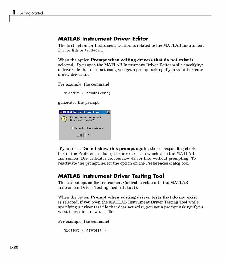
When the option Prompt when editing drivers that do not exist isselected, if you open the MATLAB Instrument Driver Editor while specifyinga driver file that does not exist, you get a prompt asking if you want to createa new driver file.
For example, the command
midedit ('newdriver')
generates the prompt
If you select Do not show this prompt again, the corresponding checkbox in the Preferences dialog box is cleared, in which case the MATLABInstrument Driver Editor creates new driver files without prompting. Toreactivate the prompt, select the option on the Preferences dialog box.
MATLAB Instrument Driver Testing ToolThe second option for Instrument Control is related to the MATLABInstrument Driver Testing Tool (midtest).
When the option Prompt when editing driver tests that do not existis selected, if you open the MATLAB Instrument Driver Testing Tool whilespecifying a driver test file that does not exist, you get a prompt asking if youwant to create a new test file.
For example, the command
midtest ('newtest')
1-28

General Preferences for Instrument Control
generates the prompt
If you select Do not show this prompt again, the corresponding check box inthe Preferences dialog box is cleared, in which case the MATLAB InstrumentDriver Testing Tool creates new driver test files without prompting. Toreactivate the prompt, check the option on the Preferences dialog box.
Device ObjectsYou access other Instrument Control Preferences by selecting theInstrument Control node in the tree.
The Device Objects section of the dialog box contains preferences related tothe construction and use of device objects for VXIplug&play and IVI-C drivers.
1-29

1 Getting Started
Here you set the minimum number of properties and functions required tocreate a device object group, and the default size of character arrays passed asoutput arguments to device object functions.
Set the default size for these character arrays in the Preferences dialog boxto ensure that they are large enough to accommodate any string returned tothem by any device object functions. You can reduce the default characterarray size to avoid unnecessary memory usage, as long as they are still largeenough to accommodate any expected strings.
IVI Configuration StoreThe IVI Configuration Store section of the dialog box contains preferencesrelated to the construction and use of IVI configuration store objects whenyou are working in the Command Window or in the Test & MeasurementTool (tmtool).
You can select either a master configuration store or a user-definedconfiguration store. If you choose a user-defined configuration store, you mustprovide its file name.
1-30

Getting Help
Getting Help
In this section...
“instrhelp Function” on page 1-31
“propinfo Function” on page 1-31
“Online Support” on page 1-33
instrhelp FunctionYou can use the instrhelp function to:
• Display command-line help for functions and properties.
• List all the functions and properties associated with a specific instrumentobject.
An instrument object is not only for you to obtain this information. Forexample, to display all functions and properties associated with a GPIBobject, as well as the constructor M-file help, type:
instrhelp gpib
To display help for the EOIMode property, type:
instrhelp EOIMode
You can also display help for an existing instrument object. For example, todisplay help for the MemorySpace property associated with a VISA-GPIB-VXIobject, type:
v = visa('agilent','GPIB-VXI0::80::INSTR');out = instrhelp(v,'MemorySpace');
Alternatively, you can display help via the Workspace browser by right-clickingan instrument object and selecting Instrument Help from the context menu.
propinfo FunctionYou can use the propinfo function to return the characteristics of InstrumentControl Toolbox properties. For example, you can find the default value for
1-31

1 Getting Started
any property using this function. propinfo returns a structure containing thefollowing fields:
Field Name Description
Type The property data type. Possible values are any,ASCII value, callback, double, string, and struct.
Constraint The type of constraint on the property value. Possiblevalues are ASCII value, bounded, callback, enum,and none.
ConstraintValue The property value constraint. The constraint can bea range of values or a list of string values.
DefaultValue The property default value.
ReadOnly The condition under which a property is read only.Possible values are always, never, whileOpen, andwhileRecording.
InterfaceSpecific If the property is interface-specific, a 1 is returned.If the property is supported for all interfaces, a 0 isreturned.
For example, to display the property characteristics for the EOIMode propertyassociated with the GPIB object g,
g = gpib('ni',0,2);EOIinfo = propinfo(g,'EOIMode')
EOIinfo =Type: 'string'
Constraint: 'enum'ConstraintValue: {2x1 cell}
DefaultValue: 'on'ReadOnly: 'never'
InterfaceSpecific: 1
This information tells you the following:
• The property value data type is a string.
• The property value is constrained as an enumerated list of values.
1-32

Getting Help
• There are two possible property values.
• The default value is on.
• The property can be configured at any time (it is never read-only).
• The property is not supported for all interfaces.
To display the property value constraints,
EOIinfo.ConstraintValueans =
'on''off'
Online SupportFor online support of Instrument Control Toolbox, visit the Web sitehttp://www.mathworks.com/support/product/IC/. This site includesdocumentation, examples, solutions, downloads, system requirements, andcontact information.
1-33

1 Getting Started
1-34
2
The Instrument ControlSession
The instrument control session consists of the steps you are likely to takewhen communicating with your instrument. This chapter highlights some ofthe differences between interface objects and device objects for each of thesesteps, to help you decide which to use in communicating with your instrument.Whether you use interface objects or device objects, the basic steps of theinstrument control session remain the same, as outlined in this chapter.
Creating Instrument Objects (p. 2-2) Create a MATLAB object thatrepresents the interface or theinstrument.
Connecting to the Instrument (p. 2-4) Establish a connection betweenthe object and the interface orinstrument.
Configuring and ReturningProperties (p. 2-5)
Read and write property valuesto configure the interface andinstrument settings.
Communicating with YourInstrument (p. 2-7)
Write commands to the instrument,read data from the instrument, orcall instrument driver functions.
Disconnecting and Cleaning Up(p. 2-8)
Disconnect the object, and removethe object from memory and fromthe workspace.
Summary (p. 2-9) Choose whether to use interfaceobjects or device objects for yourapplication.

2 The Instrument Control Session
Creating Instrument Objects
In this section...
“Overview” on page 2-2
“Interface Objects” on page 2-2
“Device Objects” on page 2-3
OverviewInstrument objects are the toolbox components you use to access yourinstrument. They provide a gateway to the functionality of your instrumentand allow you to control the behavior of your application. The toolbox supportstwo types of instrument objects:
• Interface objects — Interface objects are associated with a specific interfacestandard such as GPIB or VISA. They allow you to communicate with anyinstrument connected to the interface.
• Device objects — Device objects are associated with a MATLAB instrumentdriver. They allow you to communicate with your instrument usingproperties and functions defined in the driver for a specific instrumentmodel.
Interface ObjectsAn interface object represents a channel of communication. For example, aninterface object might represent a device at address 4 on the GPIB, eventhough there is nothing specific about what kind of instrument this may be.
To create an instrument object, you call the constructor for the type ofinterface (gpib, serial, tcpip, udp, or visa), and provide appropriateinterface information, such as address for GPIB, remote host for TCP/IP, orport number for serial.
For detailed information on interface objects and how to create and use them,see Chapter 3, “Using Interface Objects”.
2-2

Creating Instrument Objects
Device ObjectsA device object represents an instrument rather than an interface. As partof that representation, a device object must also be aware of the instrumentdriver.
You create a device object with the icdevice function. A device object requiresa MATLAB instrument driver and some form of instrument interface, whichcan be an interface object, a VISA resource name, or an interface implied inan IVI configuration.
For detailed information on device objects and how to create and use them,see Chapter 8, “Using Device Objects”.
2-3

2 The Instrument Control Session
Connecting to the InstrumentBefore you can use an instrument object to write or read data, you mustconnect it to the instrument. You connect an interface object to the instrumentwith the fopen function; you connect a device object to the instrument withthe connect function.
You can examine the Status property to verify that the instrument object isconnected to the instrument.
obj.Statusans =open
Some properties of the object are read-only while the object is connected andmust be configured before connecting. Examples of interface object propertiesthat are read-only when the object is connected include InputBufferSize andOutputBufferSize. You can determine when a property is configurable withthe propinfo function or by referring to Properties — Alphabetical List .
2-4

Configuring and Returning Properties
Configuring and Returning Properties
In this section...
“Configuring Property Names and Property Values” on page 2-5
“Returning Property Names and Property Values” on page 2-5
“Property Inspector” on page 2-6
Configuring Property Names and Property ValuesYou establish the desired instrument object behavior by configuring propertyvalues. You can configure property values using the set function or the dotnotation, or by specifying property name/property value pairs during objectcreation. You can return property values using the get function or the dotnotation.
Interface objects possess two types of properties: base properties andinterface-specific properties. (These properties pertain only to the interfaceobject itself and to the interface, not to the instrument.) Base properties aresupported for all interface objects (serial port, GPIB, VISA-VXI, and so on),while interface-specific properties are supported only for objects of a giveninterface type. For example, the BaudRate property is supported only forserial port and VISA-serial objects.
Device objects also possess two types of properties: base properties anddevice-specific properties. While device objects possess base propertiespertaining to the object and interface, they also possess any number ofdevice-specific properties as defined in the instrument driver for configuringthe instrument. For example, a device object representing an oscilloscopemight posses such properties as DisplayContrast, InputRange, andMeasurementMode. When you set these properties you are directly configuringthe oscilloscope settings.
Returning Property Names and Property ValuesOnce the instrument object is created, you can use the set function toreturn all its configurable properties to a variable or to the command line.Additionally, if a property has a finite set of string values, set returns thesevalues.
2-5

2 The Instrument Control Session
Property InspectorThe Property Inspector enables you to inspect and set properties for one ormore instrument objects. It provides a list of all properties and displaystheir current values.
Settable properties in the list are associated with an editing device thatis appropriate for the values accepted by the particular property. Forexample, a callback configuration GUI to set ErrorFcn, a pop-up menu toset RecordMode, and a text field to specify the TimerPeriod. The values forread-only properties are grayed out.
You open the Property Inspector with the inspect function. Alternatively, youcan open the Property Inspector via the Workspace browser by right-clickingan instrument object and selecting Call Property Inspector from thecontext menu, or by double-clicking the object.
2-6

Communicating with Your Instrument
Communicating with Your Instrument
In this section...
“Interface Objects and Instrument Commands” on page 2-7
“Device Objects and Instrument Drivers” on page 2-7
Interface Objects and Instrument CommandsCommunicating with your instrument involves sending and receivingcommands, settings, responses, and data. The level of communication dependson the type of instrument object you use.
To communicate through the interface object, you need to send instrumentcommands, and you receive information as the instrument sends it. Therefore,you have to know the syntax specific to the instrument itself. For example, ifthe instrument requires the command '*RST' to initiate its action, then thatis exactly the command that must be sent to the interface object.
Text commands and binary data are sent directly to the instrument andreceived from the instrument with such functions as fprintf, fwrite, fgets,fread, and others.
Device Objects and Instrument DriversTo communicate through a device object, you access object properties with theset and get commands, and you execute driver functions with the invokecommand. The invoke command for a device object employs methods andarguments defined by the instrument driver. So using device objects does notrequire you to use instrument-specific commands and syntax.
For information on creating, editing, and importing instrument drivers, seeChapter 14, “Using the Instrument Driver Editor”.
2-7

2 The Instrument Control Session
Disconnecting and Cleaning Up
In this section...
“Disconnecting an Instrument Object” on page 2-8
“Cleaning Up the MATLAB Environment” on page 2-8
Disconnecting an Instrument ObjectWhen you no longer need to communicate with the instrument, you shoulddisconnect the object. Interface objects are disconnected with the fclosefunction; device objects are disconnected with the disconnect function.
You can examine the Status property to verify that the object is disconnectedfrom the instrument.
obj.Statusans =closed
Cleaning Up the MATLAB EnvironmentWhen you no longer need the instrument object, you should remove it frommemory with the delete function.
delete(obj)
A deleted instrument object is invalid, which means that you cannot connectit to the instrument. In this case, you should remove the object from theMATLAB workspace. To remove instrument objects and other variables fromthe MATLAB workspace, use the clear command.
clear obj
If you use clear on an object that is connected to an instrument, the objectis removed from the workspace but remains connected to the instrument.You can restore cleared instrument objects to MATLAB with the instrfindfunction.
2-8

Summary
Summary
In this section...
“Advantages of Using Device Objects” on page 2-9
“When to Use Interface Objects” on page 2-9
Advantages of Using Device ObjectsShould you use interface objects or device objects to communicate with yourinstrument? Generally, device objects make instrument control easier andthey offer greater flexibility to the user compared to using interface objects.
Because of the advantages offered by using device objects for communicatingwith your instrument, you should use device objects whenever possible. Someof these advantages are
• You do not need to know instrument-specific commands
• You can use standard VXIplug&play or IVI instrument drivers provided byyour instrument vendor or other party
• You can use a MATLAB instrument driver to control your instrument. Toget a MATLAB instrument driver, you can
- Convert a VXIplug&play or IVI driver
- Use a MATLAB driver that is shipped with the toolbox
- Create it yourself or modify a similar driver
- Install it from a third party, such as MATLAB Central
You can create, convert, or customize a MATLAB instrument driver withthe MATLAB Instrument Driver Editor tool (midedit).
When to Use Interface ObjectsIn some circumstances, using device objects to communicate with yourinstrument would be impossible or impractical. You might need to useinterface objects if
2-9

2 The Instrument Control Session
• Your instrument does not have a standard instrument driver supported byInstrument Control Toolbox.
• You are using a streaming application (typically serial, UDP, or TCP/IPinterface) to notify you of some occurrence.
• Your application requires frequent changes to communication channelsettings.
2-10

3
Using Interface Objects
The instrument control session using interface objects consists of all the stepsdescribed in the following sections.
Creating an Interface Object (p. 3-2) Create a MATLAB object thatrepresents the instrument.
Connecting to the Instrument (p. 3-5) Establish a connection between theobject and the instrument.
Configuring and ReturningProperties (p. 3-6)
Define the instrument objectbehavior by assigning values toproperties.
Writing and Reading Data (p. 3-12) Write data to the instrument andread data from the instrument.
Disconnecting and Cleaning Up(p. 3-25)
Disconnect the object from theinstrument, and remove theobject from memory and from theworkspace.

3 Using Interface Objects
Creating an Interface Object
In this section...
“Object Creation Functions” on page 3-2
“Configuring Properties During Object Creation” on page 3-3
“Creating an Array of Instrument Objects” on page 3-3
Object Creation FunctionsTo create an interface object, you call M-file functions called object creationfunctions (or object constructors). These M-files are implemented using theMATLAB object-oriented programming capabilities, which are described in“Classes and Objects” in the MATLAB documentation.
Interface Object Creation Functions
Constructor Description
gpib Create a GPIB object.
serial Create a serial port object.
tcpip Create a TCPIP object.
udp Create a UDP object.
visa Create a VISA-GPIB, VISA-VXI, VISA-GPIB-VXI, orVISA-serial object.
You can find out how to create an interface object for a particular interfaceand adaptor with the ObjectConstructorName field of the instrhwinfofunction. For example, to find out how to create a GPIB object for a NationalInstruments GPIB controller,
out = instrhwinfo('gpib','ni');out.ObjectConstructorNameans =
'gpib('ni', 0, 1);'
3-2
Creating an Interface Object
Configuring Properties During Object CreationInstrument objects contain properties that reflect the functionality of yourinstrument. You control the behavior of your instrument control applicationby configuring values for these properties.
As described in “Configuring and Returning Properties” on page 3-6, youconfigure properties using the set function or the dot notation. You canalso configure properties during object creation by specifying propertyname/property value pairs. For example, the following command configuresthe EOSMode and EOSCharCode properties for the GPIB object g:
g = gpib('ni',0,1,'EOSMode','read','EOSCharCode','CR');
If you specify an invalid property name or property value, the object is notcreated. For detailed property descriptions, refer to Properties — AlphabeticalList .
Creating an Array of Instrument ObjectsIn MATLAB, you can create an array from existing variables by concatenatingthose variables. The same is true for instrument objects. For example,suppose you create the GPIB objects g1 and g2:
g1 = gpib('ni',0,1);g2 = gpib('ni',0,2);
You can now create an instrument object array consisting of g1 and g2 usingthe usual MATLAB syntax. To create the row array x:
x = [g1 g2]Instrument Object Array
Index: Type: Status: Name:1 gpib closed GPIB0-12 gpib closed GPIB0-2
To create the column array y:
y = [g1;g2];
3-3

3 Using Interface Objects
Note that you cannot create a matrix of instrument objects. For example,you cannot create the matrix
z = [g1 g2;g1 g2];??? Error using ==> gpib/vertcatOnly a row or column vector of instrument objects can be created.
Depending on your application, you might want to pass an array of instrumentobjects to a function. For example, using one call to the set function, you canconfigure both g1 and g2 to the same property value.
set(x,'EOSMode','read')
Refer to Functions — Alphabetical List to see which functions accept aninstrument object array as an input argument.
3-4

Connecting to the Instrument
Connecting to the InstrumentBefore you can use the instrument object to write or read data, you mustconnect it to the instrument whose address or port is specified in the creationfunction. You connect an interface object to the instrument with the fopenfunction.
fopen(g)
Some properties are read-only while the object is connected and must beconfigured before using fopen. Examples include the InputBufferSize andthe OutputBufferSize properties. You can determine when a property isconfigurable with the propinfo function, or by referring to Properties —Alphabetical List .
Note You can create any number of instrument objects. However, at anytime, you can connect only one instrument object to an instrument with agiven address or port.
You can examine the Status property to verify that the instrument object isconnected to the instrument.
g.Statusans =open
As illustrated below, the connection between the instrument object and theinstrument is complete, and you can write and read data.
3-5

3 Using Interface Objects
Configuring and Returning Properties
In this section...
“Base and Interface-Specific Properties” on page 3-6
“Returning Property Names and Property Values” on page 3-6
“Configuring Property Values” on page 3-9
“Specifying Property Names” on page 3-10
“Default Property Values” on page 3-10
“Property Inspector” on page 3-11
Base and Interface-Specific PropertiesYou establish the desired instrument object behavior by configuring propertyvalues. You can configure property values using the set function or the dotnotation, or by specifying property name/property value pairs during objectcreation. You can return property values using the get function or the dotnotation.
Interface objects possess two types of properties:
• Base Properties: These are supported for all interface objects (serial port,GPIB, VISA-VXI, and so on). For example, the BytesToOutput property issupported for all interface objects.
• Interface-Specific Properties: These are supported only for objects of a giveninterface type. For example, the BaudRate property is supported only forserial port and VISA-serial objects.
Returning Property Names and Property ValuesOnce the instrument object is created, you can use the set function to returnall configurable properties to a variable or to the command line. Additionally,if a property has a finite set of string values, then set also returns thesevalues.
3-6

Configuring and Returning Properties
For example, the configurable properties for the GPIB object g are shownbelow. The base properties are listed first, followed by the GPIB-specificproperties.
g = gpib('ni',0,1);set(g)
ByteOrder: [ {littleEndian} | bigEndian ]BytesAvailableFcnBytesAvailableFcnCountBytesAvailableFcnMode: [ {eosCharCode} | byte ]ErrorFcnInputBufferSizeNameOutputBufferSizeOutputEmptyFcnRecordDetail: [ {compact} | verbose ]RecordMode: [ {overwrite} | append | index ]RecordNameTagTimeoutTimerFcnTimerPeriodUserData
GPIB specific properties:BoardIndexCompareBitsEOIMode: [ {on} | off ]EOSCharCodeEOSMode: [ {none} | read | write | read&write ]PrimaryAddressSecondaryAddress
You can use the get function to return one or more properties and theircurrent values to a variable or to the command line.
For example, all the properties and their current values for the GPIB objectg are shown below. The base properties are listed first, followed by theGPIB-specific properties.
get(g)
3-7

3 Using Interface Objects
ByteOrder = littleEndianBytesAvailable = 0BytesAvailableFcn =BytesAvailableFcnCount = 48BytesAvailableFcnMode = eosCharCodeBytesToOutput = 0ErrorFcn =InputBufferSize = 512Name = GPIB0-1OutputBufferSize = 512OutputEmptyFcn =RecordDetail = compactRecordMode = overwriteRecordName = record.txtRecordStatus = offStatus = closedTag =Timeout = 10TimerFcn =TimerPeriod = 1TransferStatus = idleType = gpibUserData = []ValuesReceived = 0ValuesSent = 0
GPIB specific properties:BoardIndex = 0BusManagementStatus = [1x1 struct]CompareBits = 8EOIMode = onEOSCharCode = LFEOSMode = noneHandshakeStatus = [1x1 struct]PrimaryAddress = 1SecondaryAddress = 0
To display the current value for one property, you supply the property name toget.
3-8

Configuring and Returning Properties
get(g,'OutputBufferSize')ans =
512
To display the current values for multiple properties, you include the propertynames as elements of a cell array.
get(g,{'BoardIndex','TransferStatus'})ans =
[0] 'idle'
You can also use the dot notation to display a single property value.
g.PrimaryAddressans =
1
Configuring Property ValuesYou can configure property values using the set function
set(g,'EOSMode','read')
or the dot notation.
g.EOSMode = 'read';
To configure values for multiple properties, you can supply multiple propertyname/property value pairs to set.
set(g,'EOSCharCode','CR','Name','Test1-gpib')
Note that you can configure only one property value at a time using the dotnotation.
In practice, you can configure many of the properties at any time while theinstrument object exists — including during object creation. However, someproperties are not configurable while the object is connected to the instrumentor when recording information to disk. Use the propinfo function, or referto Properties — Alphabetical List to understand when you can configure aproperty.
3-9

3 Using Interface Objects
Specifying Property NamesInstrument object property names are presented using mixed case. While thismakes property names easier to read, you can use any case you want whenspecifying property names. Additionally, you need use only enough letters toidentify the property name uniquely, so you can abbreviate most propertynames. For example, you can configure the EOSMode property in any of theseways.
set(g,'EOSMode','read')set(g,'eosmode','read')set(g,'EOSM','read')
However, when you include property names in an M-file, you should use thefull property name. This practice can prevent problems with future releases ofInstrument Control Toolbox if a shortened name is no longer unique becauseof the addition of new properties.
Default Property ValuesIf you do not explicitly define a value for a property, then the default value isused. All configurable properties have default values.
Note Default values are provided for all instrument object properties. Forserial port objects, the default values are provided by your operating system.For GPIB and VISA instrument objects, the default values are providedby vendor-supplied tools. However, these settings are overridden by yourMATLAB code, and will have no effect on your instrument control application.
If a property has a finite set of string values, then the default value isenclosed by {} (curly braces). For example, the default value for the EOSModeproperty is none.
set(g,'EOSMode')[ {none} | read | write | read&write ]
You can also use the propinfo function, or refer to Functions — AlphabeticalList to find the default value for any property.
3-10

Configuring and Returning Properties
Property InspectorThe Property Inspector enables you to inspect and set properties for one ormore instrument objects. It provides a list of all properties and displaystheir current values.
Settable properties in the list are associated with an editing device thatis appropriate for the values accepted by the particular property. Forexample, a callback configuration GUI to set ErrorFcn, a pop-up menu toset RecordMode, and a text field to specify the TimerPeriod. The values forread-only properties are grayed out.
You open the Property Inspector with the inspect function. Alternatively, youcan open the Property Inspector via the Workspace browser by right-clickingan instrument object and selecting Call Property Inspector from thecontext menu, or by double-clicking the object.
3-11

3 Using Interface Objects
Writing and Reading Data
In this section...
“Before Performing Read/Write Operations” on page 3-12
“Writing Data” on page 3-13
“Reading Data” on page 3-19
Before Performing Read/Write OperationsCommunicating with your instrument involves writing and reading data.For example, you might write a text command to a function generator thatqueries its peak-to-peak voltage, and then read back the voltage value as adouble-precision array.
Before performing a write or read operation, you should consider these threequestions:
• What is the process by which data flows from MATLAB to the instrument,and from the instrument to MATLAB?
Instrument Control Toolbox automatically manages the data transferredbetween MATLAB and the instrument. For many common applications,you can ignore the buffering and data flow process. However, if you aretransferring a large number of values, executing an asynchronous read orwrite operation, or debugging your application, you might need to be awareof how this process works.
• Is the data to be transferred binary (numerical) or text (ASCII)?
For many instruments, writing text data means writing string commandsthat change instrument settings, prepare the instrument to return dataor status information, and so on. Writing binary data means writingnumerical values to the instrument such as calibration or waveform data.
• Will the write or read function block access to the MATLAB command line?
You control access to the MATLAB command line by specifying whethera read or write operation is synchronous or asynchronous. A synchronousoperation blocks access to the command line until the read or write functioncompletes execution. An asynchronous operation does not block access to
3-12

Writing and Reading Data
the command, and you can issue additional commands while the read orwrite function executes in the background.
There are other issues to consider when you read and write data, like theconditions under which a read or write operation completes. These issues varydepending upon the supported interface and are described in the respectiveinterface-specific chapters.
Writing Data
Functions Associated with Writing Data
Function Name Description
binblockwrite Write binblock data to the instrument.
fprintf Write text to the instrument.
fwrite Write binary data to the instrument.
stopasync Stop asynchronous read and write operations.
Properties Associated with Writing Data
Property Name Description
BytesToOutput Indicate the number of bytes currently in the outputbuffer.
OutputBufferSize Specify the size of the output buffer in bytes.
Timeout Specify the waiting time to complete a read or writeoperation.
3-13

3 Using Interface Objects
Properties Associated with Writing Data (Continued)
Property Name Description
TransferStatus Indicate if an asynchronous read or write operation isin progress.
ValuesSent Indicate the total number of values written to theinstrument.
Output Buffer and Data FlowThe output buffer is computer memory allocated by the instrument objectto store data that is to be written to the instrument. The flow of data fromMATLAB to your instrument follows these steps:
1 The data specified by the write function is sent to the output buffer.
2 The data in the output buffer is sent to the instrument.
The OutputBufferSize property specifies the maximum number of bytes thatyou can store in the output buffer. The BytesToOutput property indicatesthe number of bytes currently in the output buffer. The default values forthese properties are:
g = gpib('ni',0,1);get(g,{'OutputBufferSize','BytesToOutput'})ans =
[512] [0]
If you attempt to write more data than can fit in the output buffer, an erroris returned and no data is written.
Note When writing data, you might need to specify a value, which can consistof one or more bytes. This is because some write functions allow you to controlthe number of bits written for each value and the interpretation of those bitsas character, integer or floating-point values. For example, if you write onevalue from an instrument using the int32 format, then that value consistsof four bytes.
3-14

Writing and Reading Data
For example, suppose you write the string command *IDN? to an instrumentusing the fprintf function. As shown below, the string is first written to theoutput buffer as six values.
The *IDN? command consists of six values because the End-Of-Stringcharacter is written to the instrument, as specified by the EOSMode andEOSCharCode properties. Moreover, the default data format for the fprintffunction specifies that one value corresponds to one byte.
As shown below, after the string is stored in the output buffer, it is thenwritten to the instrument.
Example: Writing Text Data Versus Writing Binary DataFor many instruments, writing text data means writing string commands thatchange instrument settings, prepare the instrument to return data or status
3-15

3 Using Interface Objects
information, and so on. Writing binary data means writing numerical valuesto the instrument such as calibration or waveform data.
You can write text data with the fprintf function. By default, fprintfuses the %s\n format, which formats the data as a string and includes theterminator. You can write binary data with the fwrite function. By default,fwrite writes data using the uchar precision, which translates the dataas unsigned 8-bit characters. Both of these functions support many otherformats and precisions, as described in their reference pages.
The following example illustrates writing text data and binary data to aTektronix TDS 210 oscilloscope. The text data consists of string commands,while the binary data is a waveform that is to be downloaded to the scope andstored in its memory:
1 Create an instrument object — Create the GPIB object g associatedwith a National Instruments GPIB controller with board index 0, andan instrument with primary address 1. The size of the output buffer isincreased to accommodate the waveform data. You must configure theOutputBufferSize property while the GPIB object is disconnected fromthe instrument.
g = gpib('ni',0,1);g.OutputBufferSize = 3000;
2 Connect to the instrument — Connect g to the instrument.
fopen(g)
3 Write and read data — Write string commands that configure the scopeto store binary waveform data in memory location A.
fprintf(g,'DATA:DESTINATION REFA');fprintf(g,'DATA:ENCDG SRPbinary');fprintf(g,'DATA:WIDTH 1');fprintf(g,'DATA:START 1');
Create the waveform data.
t = linspace(0,25,2500);data = round(sin(t)*90 + 127);
3-16

Writing and Reading Data
Write the binary waveform data to the scope.
cmd = double('CURVE #42500');fwrite(g,[cmd data]);
The ValuesSent property indicates the total number of values that werewritten to the instrument.
g.ValuesSentans =
2577
4 Disconnect and clean up — When you no longer need g, you shoulddisconnect it from the instrument, remove it from memory, and remove itfrom the MATLAB workspace.
fclose(g)delete(g)clear g
Synchronous Versus Asynchronous Write OperationsBy default, all write functions operate synchronously and block the MATLABcommand line until the operation completes. To perform an asynchronouswrite operation, you supply the async input argument to the fprintf orfwrite function.
For example, you use the following syntax to modify the fprintf commandsused in the preceding example to write text data asynchronously.
fprintf(g,'DATA:DESTINATION REFA','async');
Similarly, you use the following syntax to modify the fwrite command usedin the preceding example to write binary data asynchronously.
fwrite(g,[cmd data],'async');
You can monitor the status of the asynchronous write operation with theTransferStatus property. A value of idle indicates that no asynchronousoperations are in progress.
g.TransferStatus
3-17

3 Using Interface Objects
ans =write
You can use the BytesToOutput property to indicate the numbers of bytesthat exist in the output buffer waiting to be written to the instrument.
g.BytesToOutputans =
2512
3-18

Writing and Reading Data
Reading Data
Functions Associated with Reading Data
Function Name Description
binblockread Read binblock data from the instrument.
fgetl Read one line of text from the instrument anddiscard the terminator.
fgets Read one line of text from the instrument andinclude the terminator.
fread Read binary data from the instrument.
fscanf Read data from the instrument, and format as text.
readasync Read data asynchronously from the instrument.
scanstr Read data from the instrument, format as text,and parse
stopasync Stop asynchronous read and write operations.
Properties Associated with Reading Data
Property Name Description
BytesAvailable Indicate the number of bytes available in the inputbuffer.
InputBufferSize Specify the size of the input buffer in bytes.
ReadAsyncMode Specify whether an asynchronous read iscontinuous or manual (serial port, TCPIP, UDP,and VISA-serial objects only).
Timeout Specify the waiting time to complete a read or writeoperation.
3-19

3 Using Interface Objects
Properties Associated with Reading Data (Continued)
Property Name Description
TransferStatus Indicate if an asynchronous read or write operationis in progress.
ValuesReceived Indicate the total number of values read from theinstrument.
Input Buffer and Data FlowThe input buffer is computer memory allocated by the instrument object tostore data that is to be read from the instrument. The flow of data from yourinstrument to MATLAB follows these steps:
1 The data read from the instrument is stored in the input buffer.
2 The data in the input buffer is returned to the MATLAB variable specifiedby the read function.
The InputBufferSize property specifies the maximum number of bytes thatyou can store in the input buffer. The BytesAvailable property indicates thenumber of bytes currently available to be read from the input buffer. Thedefault values for these properties are:
g = gpib('ni',0,1);get(g,{'InputBufferSize','BytesAvailable'})ans =
[512] [0]
If you attempt to read more data than can fit in the input buffer, an error isreturned and no data is read.
For example, suppose you use the fscanf function to read the text-basedresponse of the *IDN? command previously written to the instrument. Thedata is first read into the input buffer.
3-20
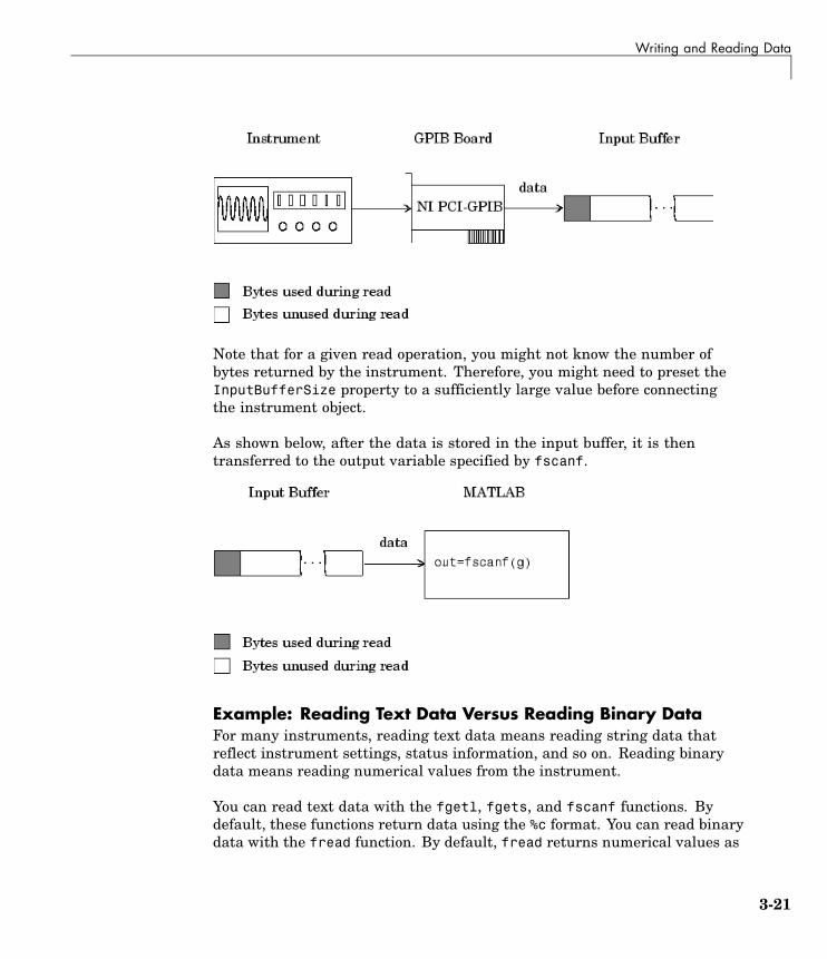
Writing and Reading Data
Note that for a given read operation, you might not know the number ofbytes returned by the instrument. Therefore, you might need to preset theInputBufferSize property to a sufficiently large value before connectingthe instrument object.
As shown below, after the data is stored in the input buffer, it is thentransferred to the output variable specified by fscanf.
Example: Reading Text Data Versus Reading Binary DataFor many instruments, reading text data means reading string data thatreflect instrument settings, status information, and so on. Reading binarydata means reading numerical values from the instrument.
You can read text data with the fgetl, fgets, and fscanf functions. Bydefault, these functions return data using the %c format. You can read binarydata with the fread function. By default, fread returns numerical values as
3-21

3 Using Interface Objects
double-precision arrays. Both the fscanf and fread functions support manyother formats and precisions, as described in their reference pages.
The following example illustrates reading text data and binary data from aTektronix TDS 210 oscilloscope, which is displaying a periodic input signalwith a nominal frequency of 1.0 kHz.
1 Create an instrument object — Create the GPIB object g associatedwith a National Instruments GPIB controller with board index 0, and aninstrument with primary address 1.
g = gpib('ni',0,1);
2 Connect to the instrument — Connect g to the instrument.
fopen(g)
3 Write and read data — Write the *IDN? command to the scope, and readback the identification information as text.
fprintf(g,'*IDN?')idn = fscanf(g)idn =TEKTRONIX,TDS 210,0,CF:91.1CT FV:v1.16 TDS2CM:CMV:v1.04
Configure the scope to return the period of the input signal, and then readthe period as a binary value. The output display format is configured to useshort exponential notation for doubles.
fprintf(g,'MEASUREMENT:MEAS1:TYPE PERIOD')fprintf(g,'MEASUREMENT:MEAS1:VALUE?')format short eperiod = fread(g,9)'period =
49 46 48 48 54 69 45 51 10
period consists of positive integers representing character codes, where 10is a line feed. To convert the voltage value to a string, use the char function.
char(period)ans =1.006E-3
3-22

Writing and Reading Data
The ValuesReceived property indicates the total number of values thatwere read from the instrument.
g.ValuesReceivedans =
65
4 Disconnect and clean up — When you no longer need g, you shoulddisconnect it from the instrument, remove it from memory, and remove itfrom the MATLAB workspace.
fclose(g)delete(g)clear g
Synchronous Versus Asynchronous Read OperationsThe fgetl, fgets, fscanf, and fread functions operate synchronously andblock the MATLAB command line until the operation completes. To performan asynchronous read operation, you use the readasync function. readasyncasynchronously reads data from the instrument and stores it in the inputbuffer. To transfer the data from the input buffer to a MATLAB variable, youuse one of the synchronous read functions.
Note For serial port, TCPIP, UDP, and VISA-serial objects, you can alsoperform an asynchronous read operation by configuring the ReadAsyncModeproperty to continuous.
For example, to modify the preceding example to asynchronously read thescope’s identification information, you would issue the readasync functionafter the *IDN? command is written.
fprintf(g,'*IDN?')readasync(g)
You can monitor the status of the asynchronous read operation with theTransferStatus property. A value of idle indicates that no asynchronousoperations are in progress.
3-23

3 Using Interface Objects
g.TransferStatusans =read
You can use the BytesAvailable property to indicate the number of bytesthat exist in the input buffer waiting to be transferred to MATLAB.
g.BytesAvailableans =
56
When the read completes, you can transfer the data as text to a MATLABvariable using the fscanf function.
idn = fscanf(g);
3-24

Disconnecting and Cleaning Up
Disconnecting and Cleaning Up
In this section...
“Disconnecting an Instrument Object” on page 3-25
“Cleaning Up the MATLAB Environment” on page 3-25
Disconnecting an Instrument ObjectWhen you no longer need an instrument object, you should disconnect it fromthe instrument, and clean up the MATLAB environment by removing theobject from memory and from the workspace.
To disconnect your communication with the instrument, use the fclosefunction.
fclose(g)
You can examine the Status property to verify that the object and theinstrument are disconnected.
g.Statusans =closed
After fclose is issued, the resources associated with g are made available,and you can once again connect an instrument object to the instrument withfopen.
Cleaning Up the MATLAB EnvironmentTo remove the instrument object from memory, use the delete function.
delete(g)
A deleted instrument object is invalid, which means that you cannot connectit to the instrument. In this case, you should remove the object from theMATLAB workspace. To remove instrument objects and other variables fromthe MATLAB workspace, use the clear command.
clear g
3-25

3 Using Interface Objects
If you use clear on an object that is connected to an instrument, the objectis removed from the workspace but remains connected to the instrument.You can restore cleared instrument objects to MATLAB with the instrfindfunction.
3-26

4
Controlling InstrumentsUsing GPIB
This chapter describes specific issues related to controlling instruments thatuse the GPIB interface.
GPIB Overview (p. 4-3) Basic features of the GeneralPurpose Interface Bus (GPIB).
Creating a GPIB Object (p. 4-15) The GPIB object establishes aconnection between MATLABand the instrument via its GPIBinterface.
Configuring the GPIB Address(p. 4-18)
The GPIB address consists of theboard index of the GPIB controller,and the primary address and(optionally) the secondary address ofthe instrument.
Writing and Reading Data (p. 4-19) Interface-specific issues related towriting and reading data with aGPIB object.
Events and Callbacks (p. 4-28) Enhance your instrument controlapplication using events andcallbacks.

4 Controlling Instruments Using GPIB
Triggers (p. 4-36) Send the GET (Group ExecuteTrigger) GPIB command to theinstrument. This command instructsall addressed Listeners to performa specified action.
Serial Polls (p. 4-39) Execute a serial poll wherethe Controller asks (polls) eachaddressed Listener to send back astatus byte that indicates whether ithas asserted the SRQ line and needsservicing.
4-2

GPIB Overview
GPIB Overview
In this section...
“What Is GPIB?” on page 4-3
“Important GPIB Features” on page 4-4
“GPIB Lines” on page 4-5
“Status and Event Reporting” on page 4-10
What Is GPIB?GPIB is a standardized interface that allows you to connect and controlmultiple devices from various vendors. GPIB is also referred to by its originalname HP-IB, or by its IEEE designation IEEE-488. The GPIB functionalityhas evolved over time, and is described in several specifications:
• The IEEE 488.1-1975 specification defines the electrical and mechanicalcharacteristics of the interface and its basic functional characteristics.
• The IEEE-488.2-1987 specification builds on the IEEE 488.1 specification todefine an acceptable minimum configuration and a basic set of instrumentcommands and common data formats.
• The Standard Commands for Programmable Instrumentation (SCPI)specification builds on the commands given by the IEEE 488.2 specificationto define a standard instrument command set that can be used by GPIB orother interfaces.
For many GPIB applications, you can communicate with your instrumentwithout detailed knowledge of how GPIB works. Communication isestablished through a GPIB object, which you create in the MATLABworkspace.
If your application is straightforward, or if you are already familiar withthe topics mentioned above, you might want to begin with “Creating a GPIBObject” on page 4-15. If you want a high-level description of all the stepsyou are likely to take when communicating with your instrument, refer toChapter 2, “The Instrument Control Session”.
4-3

4 Controlling Instruments Using GPIB
Some of the GPIB functionality is required for all GPIB devices, whileother GPIB functionality is optional. Additionally, many devices supportonly a subset of the SCPI command set, or use a different vendor-specificcommand set. Refer to your device documentation for a complete list of itsGPIB capabilities and its command set.
Important GPIB FeaturesThe important GPIB features are described below. For detailed informationabout GPIB functionality, see the appropriate references in the AppendixB, “Bibliography”.
Bus and ConnectorThe GPIB bus is a cable with two 24-pin connectors that allow you to connectmultiple devices to each other. The bus and connector have these featuresand limitations:
• You can connect up to 15 devices to a bus.
• You can connect devices in a star configuration, a linear configuration,or a combination of configurations.
• To achieve maximum data transfer rates, the cable length should notexceed 20 meters total or an average of 2 meters per device. You caneliminate these restrictions by using a bus extender.
GPIB DevicesEach GPIB device must be some combination of a Talker, a Listener, or aController. A Controller is typically a board that you install in your computer.Talkers and Listeners are typically instruments such as oscilloscopes,function generators, multimeters, and so on. Most modern instruments areboth Talkers and Listeners.
• Talkers — A Talker transmits data over the interface when addressed totalk by the Controller. There can be only one Talker at a given time.
• Listeners — A Listener receives data over the interface when addressed tolisten by the Controller. There can be up to 14 Listeners at a given time.Typically, the Controller is a Talker while one or more instruments on theGPIB are Listeners.
4-4

GPIB Overview
• Controllers — The Controller specifies which devices are Talkers orListeners. A GPIB system can contain multiple Controllers. One ofthem is designated the System Controller. However, only one Controllercan be active at a given time. The current active controller is theController-In-Charge (CIC). The CIC can pass control to an idle Controller,but only the System Controller can make itself the CIC.
When the Controller is not sending messages, then a Talker can sendmessages. Typically, the CIC is a Listener while another device is enabledas a Talker.
Each Controller is identified by a unique board index number. EachTalker/Listener is identified by a unique primary address ranging from 0to 30, and by an optional secondary address, which can be 0 or can rangefrom 96 to 126.
GPIB DataThere are two types of data that can be transferred over GPIB: instrumentdata and interface messages:
• Instrument data — Instrument data consists of vendor-specific commandsthat configure your instrument, return measurement results, and so on.For a complete list of commands supported by your instrument, refer to itsdocumentation.
• Interface messages — Interface messages are defined by the GPIB standardand consist of commands that clear the GPIB bus, address devices, returnself-test results, and so on.
Data transfer consists of one byte (8 bits) sent in parallel. The data transferrate across the interface is limited to 1 megabyte per second. However, thisdata rate is usually not achieved in practice, and is limited by the slowestdevice on the bus.
GPIB LinesGPIB consists of 24 lines, which are shared by all instruments connected tothe bus. 16 lines are used for signals, while eight lines are for ground. Thesignal lines are divided into these groups:
4-5

4 Controlling Instruments Using GPIB
• Eight data lines
• Five interface management lines
• Three handshake lines
The signal lines use a low-true (negative) logic convention with TTL levels.This means that a line is low (true or asserted) when it is a TTL low level,and a line is high (false or unasserted) when it is a TTL high level. The pinassignment scheme for a GPIB connector is shown below.
GPIB Pin and Signal Assignments
Pin Label Signal Name Pin Label Signal Name
1 DIO1 Data transfer 13 DIO5 Data transfer
2 DIO2 Data transfer 14 DIO6 Data transfer
3 DIO3 Data transfer 15 DIO7 Data transfer
4 DIO4 Data transfer 16 DIO8 Data transfer
5 EOI End Or Identify 17 REN Remote Enable
6 DAV Data Valid 18 GND DAV ground
7 NRFD Not Ready For Data 19 GND NRFD ground
8 NDAC Not Data Accepted 20 GND NDAC ground
9 IFC Interface Clear 21 GND IFC ground
10 SRQ Service Request 22 GND SRQ ground
4-6

GPIB Overview
GPIB Pin and Signal Assignments (Continued)
Pin Label Signal Name Pin Label Signal Name
11 ATN Attention 23 GND ATN ground
12 Shield Chassis ground 24 GND Signal ground
Data LinesThe eight data lines, DIO1 through DIO8, are used for transferring dataone byte at a time. DIO1 is the least significant bit, while DIO8 is the mostsignificant bit. The transferred data can be an instrument command or aGPIB interface command.
Data formats are vendor-specific and can be text-based (ASCII) or binary.GPIB interface commands are defined by the IEEE 488 standard.
Interface Management LinesThe interface management lines control the flow of data across the GPIBinterface.
GPIB Interface Management Lines
Line Description
ATN Used by the Controller to inform all devices on the GPIB thatbytes are being sent. If the ATN line is high, the bytes areinterpreted as an instrument command. If the ATN line is low,the bytes are interpreted as an interface message.
IFC Used by the Controller to initialize the bus. If the IFC line islow, the Talker and Listeners are unaddressed, and the SystemController becomes the Controller-In-Charge.
REN Used by the Controller to place instruments in remote or localprogram mode. If REN is low, all Listeners are placed in remotemode, and you cannot change their settings from the front panel.If REN is high, all Listeners are placed in local mode.
4-7

4 Controlling Instruments Using GPIB
GPIB Interface Management Lines (Continued)
Line Description
SRQ Used by Talkers to asynchronously request service from theController. If SRQ is low, then one or more Talkers requireservice (for example, an error such as invalid command wasreceived). You issue a serial poll to determine which Talkerrequested service. The poll automatically sets the SRQ line high.
EOI If the ATN line is high, the EOI line is used by Talkers to identifythe end of a byte stream such as an instrument command. If theATN line is low, the EOI line is used by the Controller to performa parallel poll (not supported by the toolbox).
You can examine the state of the interface management lines with theBusManagementStatus property.
Handshake LinesThe three handshake lines, DAV, NRFD, and NDAC, are used to transferbytes over the data lines from the Talker to one or more addressed Listeners.
Before data is transferred, all three lines must be in the proper state. Theactive Talker controls the DAV line and the Listener(s) control the NRFD andNDAC lines. The handshake process allows for error-free data transmission.
GPIB Handshake Lines
Line Description
DAV Used by the Talker to indicate that a byte can be read by theListeners.
NRFD Indicates whether the Listener is ready to receive the byte.
NDAC Indicates whether the Listener has accepted the byte.
The handshaking process follows these steps:
4-8

GPIB Overview
1 Initially, the Talker holds the DAV line high indicating no data is available,while the Listeners hold the NRFD line high and the NDAC line lowindicating they are ready for data and no data is accepted, respectively.
2 When the Talker puts data on the bus, it sets the DAV line low, whichindicates that the data is valid.
3 The Listeners set the NRFD line low, which indicates that they are notready to accept new data.
4 The Listeners set the NDAC line high, which indicates that the data isaccepted.
5 When all Listeners indicate that they have accepted the data, the Talkerasserts the DAV line indicating that the data is no longer valid. The nextbyte of data can now be transmitted.
6 The Listeners hold the NRFD line high indicating they are ready to receivedata again, and the NDAC line is held low indicating no data is accepted.
Note If the ATN line is high during the handshaking process, the informationis considered data such as an instrument command. If the ATN line is low,the information is considered a GPIB interface message.
The handshaking steps are shown below.
4-9

4 Controlling Instruments Using GPIB
You can examine the state of the handshake lines with the HandshakeStatusproperty.
Status and Event ReportingGPIB provides a system for reporting status and event information. Withthis system, you can find out if your instrument has data to return, whethera command error occurred, and so on. For many instruments, the reportingsystem consists of four 8-bit registers and two queues (output and event). Thefour registers are grouped into these two functional categories:
• Status Registers — The Status Byte Register (SBR) and Standard EventStatus Register (SESR) contain information about the state of theinstrument.
• Enable Registers — The Event Status Enable Register (ESER) and theService Request Enable Register (SRER) determine which types of events
4-10

GPIB Overview
are reported to the status registers and the event queue. ESER enablesSESR, while SRER enables SBR.
The status registers, enable registers, and output queue are shown below.
4-11

4 Controlling Instruments Using GPIB
Status Byte RegisterEach bit in the Status Byte Register (SBR) is associated with a specific type ofevent. When an event occurs, the instrument sets the appropriate bit to 1.You can enable or disable the SBR bits with the Service Request EnableRegister (SRER). You can determine which events occurred by reading theenabled SBR bits.
Status Byte Register Bits
Bit Label Description
0-3 – Instrument-specific summary messages.
4 MAV The Message Available bit indicates if data is available inthe Output Queue. MAV is 1 if the Output Queue containsdata. MAV is 0 if the Output Queue is empty.
5 ESB The Event Status bit indicates if one or more enabledevents have occurred. ESB is 1 if an enabled event occurs.ESB is 0 if no enabled events occur. You enable eventswith the Standard Event Status Enable Register.
MSS The Master Summary Status summarizes the ESB andMAV bits. MSS is 1 if either MAV or ESB is 1. MSS is0 if both MAV and ESB are 0. This bit is obtained fromthe *STB? command.
6
RQS The Request Service bit indicates that the instrumentrequests service from the GPIB controller. This bit isobtained from a serial poll.
7 – Instrument-specific summary message.
For example, if you want to know when a specific type of instrument erroroccurs, you would enable bit 5 of the SRER. Additionally, you would enable theappropriate bit of the Standard Event Status Enable Register (see “StandardEvent Status Register” on page 4-13) so that the error event of interest isreported by the ESB bit of the SBR.
4-12

GPIB Overview
Standard Event Status RegisterEach bit in the Standard Event Status Register (SESR) is associated with aspecific state of the instrument. When the state changes, the instrumentsets the appropriate bits to 1. You can enable or disable the SESR bits withthe Standard Event Status Enable Register (ESER). You can determine thestate of the instrument by reading the enabled SESR bits. The SESR bitsare described below.
Standard Event Status Register Bits
Bit Label Description
0 OPC The Operation Complete bit indicates that all commandshave completed.
1 RQC The Request Control bit is not used by most instruments.
2 QYE The Query Error bit indicates that the instrumentattempted to read an empty output buffer, or that datain the output buffer was lost.
3 DDE The Device Dependent Error bit indicates that a deviceerror occurred (such as a self-test error).
4 EXE The Execution Error bit indicates that an error occurredwhen the device was executing a command or query.
5 CME The Command Error bit indicates that a commandsyntax error occurred.
6 URQ The User Request bit is not used by most instruments.
7 PON The Power On bit indicates that the device is powered on.
For example, if you want to know when an execution error occurs, you wouldenable bit 4 of the ESER. Additionally, you would enable bit 5 of the SRER(see “Status Byte Register” on page 4-12) so that the error event of interest isreported by the ESB bit of the SBR.
4-13

4 Controlling Instruments Using GPIB
Reading and Writing Register InformationThis section describes the common GPIB commands used to read and writestatus and event register information.
GPIB Commands for Reading and Writing Register Information
Register Operation Command Description
Read *ESR? Return a decimal value that corresponds to theweighted sum of all the bits set in the SESRregister.
SESR
Write N/A You cannot write to the SESR register.
Read *ESE? Return a decimal value that corresponds to theweighted sum of all the bits enabled by the *ESEcommand.
ESER
Write *ESE Write a decimal value that corresponds to theweighted sum of all the bits you want to enable inthe SESR register.
Read *STB? Return a decimal value that corresponds to theweighted sum of all the bits set in the SBR register.This command returns the same result as a serialpoll except that the MSS bit is not cleared.
SBR
Write N/A You cannot write to the SBR register.
Read *SRE? Return a decimal value that corresponds to theweighted sum of all the bits enabled by the *SREcommand.
SRER
Write *SRE Write a decimal value that corresponds to theweighted sum of all the bits you want to enable inthe SBR register.
For example, to enable bit 4 of the SESR, you write the command *ESE 16.To enable bit 4 and bit 5 of the SESR, you write the command *ESE 48. Toenable bit 5 of the SBR, you write the command *SRE 32.
To see how to use many of these commands in the context of an instrumentcontrol session, refer to “Example: Executing a Serial Poll” on page 4-39.
4-14

Creating a GPIB Object
Creating a GPIB Object
In this section...
“Using the gpib Function” on page 4-15
“GPIB Object Display” on page 4-16
Using the gpib FunctionYou create a GPIB object with the gpib function. gpib requires the adaptorname, the GPIB board index, and the primary address of the instrument.As described in “Connecting to the Instrument” on page 2-4, you can alsoconfigure property values during object creation. For a list of supportedadaptors, refer to “Interface Driver Adaptor” on page 1-8.
Each GPIB object is associated with one controller and one instrument. Forexample, to create a GPIB object associated with a National Instrumentscontroller with board index 0, and an instrument with primary address 1,
g = gpib('ni',0,1);
Note You do not use the GPIB board primary address in the GPIB objectconstructor syntax. You use the board index and the instrument address.
The GPIB object g now exists in the MATLAB workspace. You can display theclass of g with the whos command.
whos gName Size Bytes Class
g 1x1 636 gpib object
Grand total is 14 elements using 636 bytes
Once the GPIB object is created, the following properties are automaticallyassigned values. These general-purpose properties describe the object basedon its class type and address information.
4-15

4 Controlling Instruments Using GPIB
GPIB Descriptive Properties
PropertyName
Description
Name Specify a descriptive name for the GPIB object.
Type Indicate the object type.
You can display the values of these properties for g with the get function.
get(g,{'Name','Type'})ans =
'GPIB0-1' 'gpib'
GPIB Object DisplayThe GPIB object provides you with a convenient display that summarizesimportant address and state information. You can invoke the displaysummary as follows:
• Type the GPIB object at the command line.
• Exclude the semicolon when creating a GPIB object.
• Exclude the semicolon when configuring properties using dot notation.
You can also display summary information via the Workspace browser byright-clicking an instrument object and selecting Display Summary fromthe context menu.
The display summary for the GPIB object g is:
GPIB Object Using NI Adaptor : GPIB0-1
Communication AddressBoardIndex: 0PrimaryAddress: 1SecondaryAddress: 0
Communication StateStatus: closedRecordStatus: off
4-16

Creating a GPIB Object
Read/Write StateTransferStatus: idleBytesAvailable: 0ValuesReceived: 0ValuesSent: 0
4-17

4 Controlling Instruments Using GPIB
Configuring the GPIB AddressEach GPIB object is associated with one controller and one instrument. TheGPIB address consists of the board index of the GPIB controller, and theprimary address and (optionally) the secondary address of the instrument.The term “board index” is equivalent to the term “logical unit” as used byAgilent Technologies.
Note that some vendors place limits on the allowed board index values. Referto Appendix A, “Vendor Driver Requirements and Limitations” for a list ofthese limitations. You can usually find the instrument addresses througha front panel display or by examining dip switch settings. Valid primaryaddresses range from 0 to 30. Valid secondary addresses range from 96 to 126,or can be 0, indicating that no secondary address is used.
The properties associated with the GPIB address are given below.
GPIB Address Properties
Property Name Description
BoardIndex Specify the index number of the GPIB board.
PrimaryAddress Specify the primary address of the GPIB instrument.
SecondaryAddress Specify the secondary address of the GPIB instrument.
You must specify the board index and instrument primary address valuesduring GPIB object creation. The BoardIndex and PrimaryAddress propertiesare automatically updated with these values. If the instrument has asecondary address, you can specify its value during or after object creation byconfiguring the SecondaryAddress property.
You can display the address property values for the GPIB object g created in“Creating a GPIB Object” on page 4-15 with the get function.
get(g,{'BoardIndex','PrimaryAddress','SecondaryAddress'})ans =
[0] [1] [0]
4-18

Writing and Reading Data
Writing and Reading Data
In this section...
“Rules for Completing Write and Read Operations” on page 4-19
“Example: Writing and Reading Text Data” on page 4-20
“Example: Reading Binary Data” on page 4-22
“Example: Parsing Input Data Using scanstr” on page 4-24
“Example: Understanding EOI and EOS” on page 4-25
Rules for Completing Write and Read Operations
Completing Write OperationsA write operation using fprintf or fwrite completes when one of theseconditions is satisfied:
• The specified data is written.
• The time specified by the Timeout property passes.
Additionally, you can stop an asynchronous write operation at any time withthe stopasync function.
An instrument determines if a write operation is complete based on theEOSMode, EOIMode, and EOSCharCode property values. If EOSMode isconfigured to either write or read&write, each occurrence of \n in a textcommand is replaced with the End-Of-String (EOS) character specified by theEOSCharCode value. Therefore, when you use the default fprintf format of%s\n, all text commands written to the instrument will end with that value.The default EOSCharCode value is LF, which corresponds to the line feedcharacter. The EOS character required by your instrument will be describedin its documentation.
If EOIMode is on, then the End Or Identify (EOI) line is asserted when the lastbyte is written to the instrument. The last byte can be part of a binary datastream or a text data stream. If EOSMode is configured to either write or
4-19

4 Controlling Instruments Using GPIB
read&write, then the last byte written is the EOSCharCode value and the EOIline is asserted when the instrument receives this byte.
Completing Read OperationsA read operation with fgetl, fgets, fread, fscanf, or readasync completeswhen one of these conditions is satisfied:
• The EOI line is asserted.
• The terminator specified by the EOSCharCode property is read. This canoccur only when the EOSMode property is configured to either read orread&write.
• The time specified by the Timeout property passes.
• The specified number of values is read (fread, fscanf, and readasynconly).
• The input buffer is filled (if the number of values is not specified).
In addition to these rules, you can stop an asynchronous read operation atany time with the stopasync function.
Example: Writing and Reading Text DataThis example illustrates how to communicate with a GPIB instrument bywriting and reading text data.
The instrument is a Tektronix TDS 210 two-channel oscilloscope. Therefore,many of the commands used are specific to this instrument. A sine waveis input into channel 2 of the oscilloscope, and your job is to measure thepeak-to-peak voltage of the input signal:
1 Create an instrument object — Create the GPIB object g associatedwith a National Instruments GPIB controller with board index 0, and aninstrument with primary address 1.
g = gpib('ni',0,1);
2 Connect to the instrument — Connect g to the oscilloscope, and returnthe default values for the EOSMode and EOIMode properties.
4-20

Writing and Reading Data
fopen(g)get(g,{'EOSMode','EOIMode'})ans =
'none' 'on'
Using these property values, write operations complete when the last byteis written to the instrument, and read operations complete when the EOIline is asserted by the instrument.
3 Write and read data — Write the *IDN? command to the instrumentusing fprintf, and then read back the result of the command using fscanf.
fprintf(g,'*IDN?')idn = fscanf(g)idn =TEKTRONIX,TDS 210,0,CF:91.1CT FV:v1.16 TDS2CM:CMV:v1.04
Determine the measurement source. Possible measurement sources includechannel 1 and channel 2 of the oscilloscope.
fprintf(g,'MEASUREMENT:IMMED:SOURCE?')source = fscanf(g)source =CH1
The scope is configured to return a measurement from channel 1. Becausethe input signal is connected to channel 2, you must configure theinstrument to return a measurement from this channel.
fprintf(g,'MEASUREMENT:IMMED:SOURCE CH2')fprintf(g,'MEASUREMENT:IMMED:SOURCE?')source = fscanf(g)source =CH2
You can now configure the scope to return the peak-to-peak voltage,request the value of this measurement, and then return the voltage valueto MATLAB using fscanf.
fprintf(g,'MEASUREMENT:MEAS1:TYPE PK2PK')fprintf(g,'MEASUREMENT:MEAS1:VALUE?')ptop = fscanf(g)
4-21
4 Controlling Instruments Using GPIB
ptop =2.0199999809E0
4 Disconnect and clean up — When you no longer need g, you shoulddisconnect it from the instrument, and remove it from memory and fromthe MATLAB workspace.
fclose(g)delete(g)clear g
Example: Reading Binary DataThis example illustrates how you can download the TDS 210 oscilloscopescreen display to MATLAB. The screen display data is transferred to MATLABand saved to disk using the Windows bitmap format. This data provides apermanent record of your work, and is an easy way to document importantsignal and scope parameters:
1 Create an instrument object — Create the GPIB object g associatedwith a National Instruments GPIB controller with board index 0, and aninstrument with primary address 1.
g = gpib('ni',0,1);
2 Configure property values — Configure the input buffer to accept areasonably large number of bytes, and configure the timeout value to twominutes to account for slow data transfer.
g.InputBufferSize = 50000;g.Timeout = 120;
3 Connect to the instrument — Connect g to the oscilloscope.
fopen(g)
4 Write and read data — Configure the scope to transfer the screen displayas a bitmap.
fprintf(g,'HARDCOPY:PORT GPIB')fprintf(g,'HARDCOPY:FORMAT BMP')fprintf(g,'HARDCOPY START')
4-22

Writing and Reading Data
Asynchronously transfer the data from the instrument to the input buffer.
readasync(g)
Wait until the read operation completes, and then transfer the data to theMATLAB workspace as unsigned 8-bit integers.
g.TransferStatusans =idleout = fread(g,g.BytesAvailable,'uint8');
5 Disconnect and clean up — When you no longer need g, you shoulddisconnect it from the instrument, and remove it from memory and fromthe MATLAB workspace.
fclose(g)delete(g)clear g
Viewing the Bitmap DataTo view the bitmap data, you should follow these steps:
1 Open a disk file.
2 Write the data to the disk file.
3 Close the disk file.
4 Read the data using the imread function.
5 Scale and display the data using the imagesc function.
Note that the MATLAB file I/O versions of the fopen, fwrite, and fclosefunctions are used.
fid = fopen('test1.bmp','w');fwrite(fid,out,'uint8');fclose(fid)a = imread('test1.bmp','bmp');imagesc(fliplr(a'))
4-23

4 Controlling Instruments Using GPIB
Because the scope returns the screen display data using only two colors, anappropriate colormap is selected.
mymap = [0 0 0; 1 1 1];colormap(mymap)
The resulting bitmap image is shown below.
Example: Parsing Input Data Using scanstrThis example illustrates how to use the scanstr function to parse data thatyou read from a Tektronix TDS 210 oscilloscope. scanstr is particularlyuseful when you want to parse a string into one or more cell array elements,where each element is determined to be either a double or a string:
1 Create an instrument object — Create the GPIB object g associatedwith a National Instruments GPIB controller with board index 0, and aninstrument with primary address 1.
g = gpib('ni',0,1);
2 Connect to the instrument — Connect g to the oscilloscope.
4-24

Writing and Reading Data
fopen(g)
3 Write and read data — Return identification information to separateelements of a cell array using the default delimiters.
fprintf(g,'*IDN?');idn = scanstr(g)idn =
'TEKTRONIX''TDS 210'[ 0]'CF:91.1CT FV:v1.16 TDS2CM:CMV:v1.04'
4 Disconnect and clean up — When you no longer need g, you shoulddisconnect it from the instrument, and remove it from memory and fromthe MATLAB workspace.
fclose(g)delete(g)clear g
Example: Understanding EOI and EOSThis example illustrates how the EOI line and the EOS character are usedto complete read and write operations, and how the EOIMode, EOSMode, andEOSCharCode properties are related to each other. In most cases, you cansuccessfully communicate with your instrument by accepting the defaultvalues for these properties.
The default value for EOIMode is on, which means that the EOI line isasserted when the last byte is written to the instrument. The default value forEOSMode is none, which means that the EOSCharCode value is not written tothe instrument, and read operations will not complete when the EOSCharCodevalue is read. Therefore, when you use the default values for EOIMode andEOSMode,
• Write operations complete when the last byte is written to the instrument.
• Read operations complete when the EOI line is asserted by the instrument.
4-25

4 Controlling Instruments Using GPIB
1 Create an instrument object — Create the GPIB object g associatedwith a National Instruments GPIB controller with board index 0, and aninstrument with primary address 1.
g = gpib('ni',0,1);
2 Connect to the instrument — Connect g to the oscilloscope.
fopen(g)
3 Write and read data — Configure g so that the EOI line is not assertedafter the last byte is written to the instrument, and the EOS character isused to complete write operations. The default format for fprintf is %s\n,where \n is replaced by the EOS character as given by EOSCharCode.
g.EOIMode = 'off';g.EOSMode = 'write';fprintf(g,'*IDN?')out = fscanf(g)out =
TEKTRONIX,TDS 210,0,CF:91.1CT FV:v1.16 TDS2CM:CMV:v1.04
Although EOSMode is configured so that read operations will not completeafter receiving the EOS character, the preceding read operation succeededbecause the EOI line was asserted.
Now configure g so that the EOS character is not used to complete reador write operations. Because the EOI line is not asserted and the EOScharacter is not written, the instrument cannot interpret the *IDN?command and a timeout occurs.
g.EOSMode = 'none';fprintf(g,'*IDN?')out = fscanf(g)
Warning: GPIB: NI: An I/O operation has been canceled mostlylikely due to a timeout.
Now configure g so that the read operation terminates after the “X”character is read. The EOIMode property is configured to on so that theEOI line is asserted after the last byte is written. The EOSMode property
4-26

Writing and Reading Data
is configured to read so that the read operation completes when theEOSCharCode value is read.
g.EOIMode = 'on';g.EOSMode = 'read';g.EOSCharCode = 'X';fprintf(g,'*IDN?')out = fscanf(g)out =
TEKTRONIX
Note that the rest of the identification string remains in the instrument’shardware buffer. If you do not want to return this data during the nextread operation, you should clear it from the instrument buffer with theclrdevice function.
clrdevice(g)
4 Disconnect and clean up — When you no longer need g, you shoulddisconnect it from the instrument, and remove it from memory and fromthe MATLAB workspace.
fclose(g)delete(g)clear g
4-27

4 Controlling Instruments Using GPIB
Events and Callbacks
In this section...
“Example: Introduction to Events and Callbacks” on page 4-28
“Event Types and Callback Properties” on page 4-29
“Storing Event Information” on page 4-30
“Creating and Executing Callback Functions” on page 4-32
“Enabling Callback Functions After They Error” on page 4-33
“Example: Using Events and Callbacks to Read Binary Data” on page 4-33
Example: Introduction to Events and CallbacksYou can enhance the power and flexibility of your instrument controlapplication by using events. An event occurs after a condition is met, andmight result in one or more callbacks.
While the instrument object is connected to the instrument, you can useevents to display a message, display data, analyze data, and so on. Callbacksare controlled through callback properties and callback functions. All eventtypes have an associated callback property. Callback functions are M-filefunctions that you construct to suit your specific application needs.
You execute a callback when a particular event occurs by specifying the nameof the M-file callback function as the value for the associated callback property.
This example uses the M-file callback function instrcallback to display amessage to the command line when a bytes-available event occurs. The eventis generated when the EOSCharCode property value is read.
g = gpib('ni',0,1);g.BytesAvailableFcnMode = 'eosCharCode';g.BytesAvailableFcn = @instrcallback;fopen(g)fprintf(g,'*IDN?')readasync(g)
The resulting display from instrcallback is shown below.
4-28

Events and Callbacks
BytesAvailable event occurred at 17:30:11 for the object: GPIB0-1.
End the GPIB session.
fclose(g)delete(g)clear g
You can use the type command to display instrcallback at the commandline.
Event Types and Callback PropertiesThe GPIB event types and associated callback properties are described below.
GPIB Event Types and Callback Properties
Event Type Associated Property Name
BytesAvailableFcn
BytesAvailableFcnCount
Bytes-available
BytesAvailableFcnMode
Error ErrorFcn
Output-empty OutputEmptyFcn
TimerFcnTimer
TimerPeriod
Bytes-Available EventA bytes-available event is generated immediately after a predeterminednumber of bytes are available in the input buffer or the End-Of-Stringcharacter is read, as determined by the BytesAvailableFcnMode property.
If BytesAvailableFcnMode is byte, the bytes-available event executes thecallback function specified for the BytesAvailableFcn property every timethe number of bytes specified by BytesAvailableFcnCount is stored in theinput buffer. If BytesAvailableFcnMode is eosCharCode, then the callback
4-29
4 Controlling Instruments Using GPIB
function executes every time the character specified by the EOSCharCodeproperty is read.
This event can be generated only during an asynchronous read operation.
Error EventAn error event is generated immediately after an error, such as a timeout,occurs. A timeout occurs if a read or write operation does not successfullycomplete within the time specified by the Timeout property. An error eventis not generated for configuration errors such as setting an invalid propertyvalue.
This event executes the callback function specified for the ErrorFcn property.It can be generated only during an asynchronous read or write operation.
Output-Empty EventAn output-empty event is generated immediately after the output buffer isempty.
This event executes the callback function specified for the OutputEmptyFcnproperty. It can be generated only during an asynchronous write operation.
Timer EventA timer event is generated when the time specified by the TimerPeriodproperty passes. Time is measured relative to when the object is connected tothe instrument.
This event executes the callback function specified for the TimerFcn property.Note that some timer events might not be processed if your system issignificantly slowed or if the TimerPeriod value is too small.
Storing Event InformationYou can store event information in a callback function or in a record file. Eventinformation stored in a callback function uses two fields: Type and Data. TheType field contains the event type, while the Data field contains event-specificinformation. As described in “Creating and Executing Callback Functions” onpage 4-32, these two fields are associated with a structure that you define in
4-30

Events and Callbacks
the callback function header. Refer to “Debugging: Recording Information toDisk” on page 12-6 to learn about storing event information in a record file.
The event types and the values for the Type and Data fields are given below.
GPIB Event Information
Event Type Field Field Value
Type BytesAvailableBytes available
Data.AbsTime day-month-yearhour:minute:second
Type Error
Data.AbsTime day-month-yearhour:minute:second
Error
Data.Message An error string
Type OutputEmptyOutput empty
Data.AbsTime day-month-yearhour:minute:second
Type TimerTimer
Data.AbsTime day-month-yearhour:minute:second
The Data field values are described below.
AbsTime FieldAbsTime is defined for all events, and indicates the absolute time the eventoccurred. The absolute time is returned using the MATLAB clock format:
day-month-year hour:minute:second
Message FieldMessage is used by the error event to store the descriptive message that isgenerated when an error occurs.
4-31

4 Controlling Instruments Using GPIB
Creating and Executing Callback FunctionsYou specify the callback function to be executed when a specific event typeoccurs by including the name of the M-file as the value for the associatedcallback property. You can specify the callback function as a function handleor as a string cell array element. Function handles are described in theMATLAB function_handle reference page. Note that if you are executinga local callback function from within an M-file, then you must specify thecallback as a function handle.
For example, to execute the callback function mycallback every time theEOSCharCode property value is read from your instrument,
g.BytesAvailableFcnMode = 'eosCharCode';g.BytesAvailableFcn = @mycallback;
Alternatively, you can specify the callback function as a cell array.
g.BytesAvailableFcn = {'mycallback'};
M-file callback functions require at least two input arguments. The firstargument is the instrument object. The second argument is a variable thatcaptures the event information given in the preceding table, GPIB EventInformation on page 4-31. This event information pertains only to theevent that caused the callback function to execute. The function header formycallback is shown below.
function mycallback(obj,event)
You pass additional parameters to the callback function by including both thecallback function and the parameters as elements of a cell array. For example,to pass the MATLAB variable time to mycallback,
time = datestr(now,0);g.BytesAvailableFcnMode = 'eosCharCode';g.BytesAvailableFcn = {@mycallback,time};
Alternatively, you can specify mycallback as a string in the cell array.
g.BytesAvailableFcn = {'mycallback',time};
The corresponding function header is
4-32

Events and Callbacks
function mycallback(obj,event,time)
If you pass additional parameters to the callback function, then they must beincluded in the function header after the two required arguments.
Note You can also specify the callback function as a string. In this case, thecallback is evaluated in the MATLAB workspace and no requirements aremade on the input arguments of the callback function.
Enabling Callback Functions After They ErrorIf an error occurs while a callback function is executing, then
• The callback function is automatically disabled.
• A warning is displayed at the command line, indicating that the callbackfunction is disabled.
If you want to enable the same callback function, you can set the callbackproperty to the same value or you can disconnect the object with the fclosefunction. If you want to use a different callback function, the callback will beenabled when you configure the callback property to the new value.
Example: Using Events and Callbacks to Read BinaryDataThis example extends “Example: Reading Binary Data” on page 4-22 byusing the M-file callback function instrcallback to display event-relatedinformation to the command line when a bytes-available event occurs duringa binary read operation:
1 Create an instrument object — Create the GPIB object g associatedwith a National Instruments GPIB controller with board index 0, and aninstrument with primary address 1.
g = gpib('ni',0,1);
4-33

4 Controlling Instruments Using GPIB
2 Configure properties — Configure the input buffer to accept a reasonablylarge number of bytes, and configure the timeout value to two minutesto account for slow data transfer.
g.InputBufferSize = 50000;g.Timeout = 120;
Configure g to execute the callback function instrcallback everytime 5000 bytes is stored in the input buffer. Because instrcallbackrequires an instrument object and event information to be passed as inputarguments, the callback function is specified as a function handle.
g.BytesAvailableFcnMode = 'byte';g.BytesAvailableFcnCount = 5000;g.BytesAvailableFcn = @instrcallback;
3 Connect to the instrument — Connect g to the oscilloscope.
fopen(g)
4 Write and read data — Configure the scope to transfer the screen displayas a bitmap.
fprintf(g,'HARDCOPY:PORT GPIB')fprintf(g,'HARDCOPY:FORMAT BMP')fprintf(g,'HARDCOPY START')
Initiate the asynchronous read operation, and begin generating events.
readasync(g)
instrcallback is called every time 5000 bytes is stored in the input buffer.The resulting displays are shown below.
BytesAvailable event occurred at 09:41:42 for the object: GPIB0-1.BytesAvailable event occurred at 09:41:50 for the object: GPIB0-1.BytesAvailable event occurred at 09:41:58 for the object: GPIB0-1.BytesAvailable event occurred at 09:42:06 for the object: GPIB0-1.BytesAvailable event occurred at 09:42:14 for the object: GPIB0-1.BytesAvailable event occurred at 09:42:22 for the object: GPIB0-1.BytesAvailable event occurred at 09:42:30 for the object: GPIB0-1.
4-34
Events and Callbacks
Wait until all the data is sent to the input buffer, and then transfer the datato MATLAB as unsigned 8-bit integers.
g.TransferStatusans =idleout = fread(g,g.BytesAvailable,'uint8');
5 Disconnect and clean up — When you no longer need g, you shoulddisconnect it from the instrument, and remove it from memory and fromthe MATLAB workspace.
fclose(g)delete(g)clear g
4-35

4 Controlling Instruments Using GPIB
Triggers
In this section...
“Using the trigger Function” on page 4-36
“Example: Executing a Trigger” on page 4-36
Using the trigger FunctionYou can execute a trigger with the trigger function. This function isequivalent to writing the GET (Group Execute Trigger) GPIB command tothe instrument.
trigger instructs all the addressed Listeners to perform someinstrument-specific function such as taking a measurement. Refer to yourinstrument documentation to learn how to use its triggering capabilities.
Example: Executing a TriggerThis example illustrates GPIB triggering using an Agilent 33120A functiongenerator. The output of the function generator is displayed with anoscilloscope so that you can observe the trigger.
1 Create an instrument object — Create the GPIB object g associatedwith a National Instruments GPIB controller with board index 0, and aninstrument with primary address 1.
g = gpib('ni',0,1);
2 Connect to the instrument — Connect g to the function generator.
fopen(g)
3 Write and read data — Configure the function generator to produce a5000 Hz sine wave, with 6 volts peak-to-peak.
fprintf(g,'Func:Shape Sin')fprintf(g,'Volt 3')fprintf(g,'Freq 5000')
4-36

Triggers
Configure the burst of the trigger to display the sine wave for five seconds,configure the function generator to expect the trigger from the GPIB board,and enable the burst mode.
fprintf(g,'BM:NCycles 25000')fprintf(g,'Trigger:Source Bus')fprintf(g,'BM:State On')
Trigger the instrument.
trigger(g)
Disable the burst mode.
fprintf(g,'BM:State Off')
While the function generator is triggered, the sine wave is saved to the RefA memory location of the oscilloscope. The saved waveform is shown below.
4-37

4 Controlling Instruments Using GPIB
4 Disconnect and clean up — When you no longer need g, you shoulddisconnect it from the instrument, and remove it from memory and fromthe MATLAB workspace.
fclose(g)delete(g)clear g
4-38

Serial Polls
Serial Polls
In this section...
“Using the spoll Function” on page 4-39
“Example: Executing a Serial Poll” on page 4-39
Using the spoll FunctionYou can execute a serial poll with the spoll function. In a serial poll, theController asks (polls) each addressed Listener to send back a status byte thatindicates whether it has asserted the SRQ line and needs servicing. Theseventh bit of this byte (the RQS bit) is set if the instrument is requestingservice.
The Controller performs the following steps for every addressed Listener:
1 The Listener is addressed to talk and the Serial Poll Enable (SPE)command byte is sent.
2 The ATN line is set high and the Listener returns the status byte.
3 The ATN line is set low and the Serial Poll Disable (SPD) command byte issent to end the poll sequence.
Refer to “Status and Event Reporting” on page 4-10 for more information onthe GPIB bus lines and the RQS bit.
Example: Executing a Serial PollThis example shows you how to execute a serial poll for an Agilent 33120Afunction generator and a Tektronix TDS 210 oscilloscope. In doing so, theexample shows you how to configure many of the status bits described in“Standard Event Status Register” on page 4-13:
1 Create instrument objects — Create a GPIB object associated with anAgilent 33120A function generator at primary address 1.
g1 = gpib('ni',0,1);
4-39

4 Controlling Instruments Using GPIB
Create a GPIB object associated with a Tektronix TDS 210 oscilloscopeat primary address 2.
g2 = gpib('ni',0,2);
2 Connect to the instrument — Connect g1 to the function generator andconnect g2 to the oscilloscope.
fopen([g1 g2])
3 Configure property values — Configure both objects to time out after 1second.
set([g1 g2],'Timeout',1)
4 Write and read data — Configure the function generator to requestservice when a command error occurs.
fprintf(g1,'*CLS');fprintf(g1,'*ESE 32');fprintf(g1,'*SRE 32');
Configure the oscilloscope to request service when a command error occurs.
fprintf(g2,'*CLS')fprintf(g2,'*PSC 0')fprintf(g2,'*ESE 32')fprintf(g2,'DESE 32')fprintf(g2,'*SRE 32')
Determine if any instrument needs servicing.
spoll([g1 g2])ans =[]
Query the voltage value for each instrument.
fprintf(g1,'Volt?')fprintf(g2,'Volt?')
4-40

Serial Polls
Determine if either instrument produced an error due to the precedingquery.
out = spoll([g1 g2]);
Because Volt? is an invalid command for the oscilloscope, it is requestingservice.
out == [g1 g2]ans =0 1
Because Volt? is a valid command for the function generator, the value isread back successfully.
volt1 = fscanf(g1)volt1 =+1.00000E-01
However, the oscilloscope read operation times out after 1 second.
volt2 = fscanf(g2)Warning: GPIB: NI: An I/O operation has been canceled, most likelydue to a timeout.
volt2 =''
5 Disconnect and clean up — When you no longer need g1 and g2, youshould disconnect them from the instruments, and remove them frommemory and from the MATLAB workspace.
fclose([g1 g2])delete([g1 g2])clear g1 g2
4-41

4 Controlling Instruments Using GPIB
4-42

5
Controlling InstrumentsUsing VISA
This chapter describes specific issues related to controlling instruments thatuse the VISA standard.
VISA Overview (p. 5-3) Brief description of the VirtualInstrument Standard Architecture(VISA) standard.
Working with the GPIB Interface(p. 5-5)
The VISA-GPIB object establishesa connection between MATLABand the instrument via its GPIBinterface.
Working with the VXI Interface(p. 5-9)
The VISA-VXI object establishes aconnection between MATLAB andthe instrument via its VXI interface.
Working with the GPIB-VXIInterface (p. 5-22)
The VISA-GPIB-VXI objectestablishes a connection betweenMATLAB and the instrument via itsGPIB-VXI interface.
Working with the Serial PortInterface (p. 5-27)
The VISA serial object establishes aconnection between MATLAB andthe instrument via the serial port.
Working with the USB Interface(p. 5-31)
The VISA-USB object establishes aconnection between MATLAB andthe instrument via its USB interface.
5 Controlling Instruments Using VISA
Working with the TCP/IP Interface(p. 5-35)
The VISA-TCPIP object establishesa connection between MATLABand the instrument using theinstrument’s IP configuration.
Working with the RSIB Interface(p. 5-39)
The VISA-RSIB object establishes aconnection between MATLAB andthe instrument via the Rohde &Schwarz VISA passport.
5-2

VISA Overview
VISA Overview
In this section...
“What Is VISA?” on page 5-3
“Interfaces Used with VISA” on page 5-3
What Is VISA?Virtual Instrument Standard Architecture (VISA) is a standard defined byAgilent Technologies and National Instruments for communicating withinstruments regardless of the interface.
Instrument Control Toolbox supports the GPIB, VXI, GPIB-VXI, and serialport interfaces using the VISA standard. Communication is establishedthrough a VISA instrument object, which you create in the MATLABworkspace. For example, a VISA-GPIB object allows you to use the VISAstandard to communicate with an instrument that possesses a GPIB interface.
Note Most features associated with VISA instrument objects are identicalto the features associated with GPIB and serial port objects. Therefore,this chapter presents only interface-specific functions and properties. Forexample, register-based communication is discussed for VISA-VXI objects,but message-based communication is not discussed as this topic is coveredelsewhere in this guide.
Interfaces Used with VISAFor many VISA applications, you can communicate with your instrumentwithout detailed knowledge of how the interface works. In this case, youmight want to begin with one of these topics:
• “Working with the GPIB Interface” on page 5-5
• “Working with the VXI Interface” on page 5-9
• “Working with the GPIB-VXI Interface” on page 5-22
• “Working with the Serial Port Interface” on page 5-27
5-3

5 Controlling Instruments Using VISA
• “Working with the USB Interface” on page 5-31
• “Working with the TCP/IP Interface” on page 5-35
• “Working with the RSIB Interface” on page 5-39
If you want a high-level description of all the steps you are likely to take whencommunicating with your instrument, refer to Chapter 2, “The InstrumentControl Session”.
Caution Instrument Control Toolbox does not support secondary VISAinstallations. The vendor that you specify when creating a VISA object shouldrefer to the primary VISA installation only. Referring to a secondary VISAinstallation could generate unpredictable results.
5-4

Working with the GPIB Interface
Working with the GPIB Interface
In this section...
“Understanding VISA-GPIB” on page 5-5
“Creating a VISA-GPIB Object” on page 5-5
“The VISA-GPIB Address” on page 5-7
Understanding VISA-GPIBThe GPIB interface is supported through a VISA-GPIB object. The featuresassociated with a VISA-GPIB object are similar to the features associatedwith a GPIB object. Therefore, only functions and properties that are uniqueto VISA’s GPIB interface are discussed in this section.
Refer to Chapter 4, “Controlling Instruments Using GPIB”, to learn about theGPIB interface, writing and reading text and binary data, using events andcallbacks, using triggers, and so on.
Note The VISA-GPIB object does not support the spoll function, or theBusManagementStatus, CompareBits, and HandshakeStatus properties.
Creating a VISA-GPIB ObjectYou create a VISA-GPIB object with the visa function. Each VISA-GPIBobject is associated with
• A GPIB controller installed in your computer
• An instrument with a GPIB interface
visa requires the vendor name and the resource name as input arguments.The vendor name can be agilent, ni, or tek. The resource name consists ofthe GPIB board index, the instrument primary address, and the instrumentsecondary address. You can find the VISA-GPIB resource name for a giveninstrument with the configuration tool provided by your vendor, or withthe instrhwinfo function. (In place of the resource name, you can use analias as defined with your VISA vendor configuration tool.) As described in
5-5

5 Controlling Instruments Using VISA
“Connecting to the Instrument” on page 2-4, you can also configure propertiesduring object creation.
For example, to create a VISA-GPIB object associated with a NationalInstruments controller with board index 0, and a Tektronix TDS 210 digitaloscilloscope with primary address 1 and secondary address 0,
vg = visa('ni','GPIB0::1::0::INSTR');
The VISA-GPIB object vg now exists in the MATLAB workspace. You candisplay the class of vg with the whos command.
whos vgName Size Bytes Class
vg 1x1 884 visa object
Grand total is 16 elements using 884 bytes
After you create the VISA-GPIB object, the following properties areautomatically assigned values. These properties provideinformation aboutthe object based on its class type and address information.
VISA-GPIB Descriptive Properties
Property Name Description
Name Specify a descriptive name for the VISA-GPIB object.
RsrcName Indicate the resource name for a VISA instrument.
Type Indicate the object type.
You can display the values of these properties for vg with the get function.
get(vg,{'Name','RsrcName','Type'})ans ='VISA-GPIB0-1' 'GPIB0::1::0::INSTR' 'visa-gpib'
5-6

Working with the GPIB Interface
VISA-GPIB Object DisplayThe VISA-GPIB object provides a convenient display that summarizesimportant address and state information. You can invoke the displaysummary as follows:
• Type the VISA-GPIB object at the command line.
• Exclude the semicolon when creating a VISA-GPIB object.
• Exclude the semicolon when configuring properties using dot notation.
You can also display summary information via the Workspace browser byright-clicking an instrument object and selecting Display Summary fromthe context menu.
The display summary for the VISA-GPIB object vg is given below.
VISA-GPIB Object Using NI Adaptor : VISA-GPIB0-1
Communication AddressBoardIndex: 0PrimaryAddress: 1SecondaryAddress: 0
Communication StateStatus: closedRecordStatus: off
Read/Write StateTransferStatus: idleBytesAvailable: 0ValuesReceived: 0ValuesSent: 0
The VISA-GPIB AddressThe VISA-GPIB address consists of
• The board index of the GPIB controller installed in your computer.
• The primary address and secondary address of the instrument. Validprimary addresses range from 0 to 30. Valid secondary addresses range
5-7

5 Controlling Instruments Using VISA
from 0 to 30, where the value 0 indicates that the secondary address isnot used.
You must specify the primary address value via the resource name duringVISA-GPIB object creation. Additionally, you must include the board indexand secondary address values as part of the resource name if they differ fromthe default value of 0.
The properties associated with the GPIB address are given below.
VISA-GPIB Address Properties
Property Name Description
BoardIndex Specify the index number of the GPIB board.
PrimaryAddress Specify the primary address of the GPIB instrument.
SecondaryAddress Specify the secondary address of the GPIB instrument.
The BoardIndex, PrimaryAddress, and SecondaryAddress properties areautomatically updated with the specified resource name values when youcreate the VISA-GPIB object.
You can display the address property values for the VISA-GPIB object vgcreated in “Creating a VISA-GPIB Object” on page 5-5 with the get function.
get(vg,{'BoardIndex','PrimaryAddress','SecondaryAddress'})ans =
[0] [1] [0]
5-8

Working with the VXI Interface
Working with the VXI Interface
In this section...
“Understanding VISA-VXI ” on page 5-9
“Creating a VISA-VXI Object” on page 5-10
“The VISA-VXI Address” on page 5-12
“Register-Based Communication” on page 5-12
Understanding VISA-VXIThe VXI interface is associated with a VXI controller that you install in slot0 of a VXI chassis. This interface, along with the other relevant hardware,is shown below.
The VXI interface is supported through a VISA-VXI object. Many of thefeatures associated with a VISA-VXI object are similar to the featuresassociated with other instrument objects. Therefore, only functions andproperties that are unique to VISA’s VXI interface are discussed in thissection.
5-9

5 Controlling Instruments Using VISA
Refer to Chapter 4, “Controlling Instruments Using GPIB”, to learn aboutgeneral toolbox capabilities such as writing and reading text and binary data,using events and callbacks, and so on.
Creating a VISA-VXI ObjectYou create a VISA-VXI object with the visa function. Each object is associatedwith
• A VXI chassis
• A VXI controller in slot 0 of the VXI chassis
• An instrument installed in the VXI chassis
visa requires the vendor name and the resource name as input arguments.The vendor name is either agilent or ni. The resource name consists ofthe VXI chassis index and the instrument logical address. You can find theVISA-VXI resource name for a given instrument with the configuration toolprovided by your vendor, or with the instrhwinfo function. (In place ofthe resource name, you can use an alias as defined with your VISA vendorconfiguration tool.) As described in “Connecting to the Instrument” on page2-4, you can also configure property values during object creation.
For example, to create a VISA-VXI object associated with a VXI chassis withindex 0 and an Agilent E1432A 16-channel digitizer with logical address 32,
vv = visa('agilent','VXI0::32::INSTR');
The VISA-VXI object vv now exists in the MATLAB workspace. You candisplay the class of vv with the whos command.
whos vvName Size Bytes Class
vv 1x1 882 visa object
Grand total is 15 elements using 882 bytes
After you create the VISA-VXI object, the following properties areautomatically assigned values. These properties provide information aboutthe object based on its class type and address information.
5-10

Working with the VXI Interface
VISA-VXI Descriptive Properties
Property Name Description
Name Specify a descriptive name for the VISA-VXI object.
RsrcName Indicate the resource name for a VISA instrument.
Type Indicate the object type.
You can display the values of these properties for vv with the get function.
get(vv,{'Name','RsrcName','Type'})ans =
'VISA-VXI0-32' 'VXI0::32::INSTR' 'visa-vxi'
The VISA-VXI Object DisplayThe VISA-VXI object provides you with a convenient display that summarizesimportant address and state information. You can invoke the displaysummary these three ways:
• Type the VISA-VXI object at the command line.
• Exclude the semicolon when creating a VISA-VXI object.
• Exclude the semicolon when configuring properties using the dot notation.
The display summary for the VISA-VXI object vv is given below.
VISA-VXI Object Using AGILENT Adaptor : VISA-VXI0-32
Communication AddressChassisIndex: 0LogicalAddress: 32
Communication StateStatus: closedRecordStatus: off
Read/Write StateTransferStatus: idleBytesAvailable: 0
5-11

5 Controlling Instruments Using VISA
ValuesReceived: 0ValuesSent: 0
The VISA-VXI AddressThe VISA-VXI address consists of
• The chassis index of the VXI chassis
• The logical address of the instrument installed in the VXI chassis
You must specify the logical address value via the resource name duringVISA-VXI object creation. Additionally, you must include the chassis indexvalue as part of the resource name if it differs from the default value of 0. Theproperties associated with the chassis and instrument address are as follows:
VISA-VXI Address Properties
Property Name Description
ChassisIndex Indicate the index number of the VXI chassis.
LogicalAddress Specify the logical address of the VXI instrument.
Slot Indicate the slot location of the VXI instrument.
The ChassisIndex and LogicalAddress properties are automatically updatedwith the specified resource name values when you create the VISA-VXI object.The Slot property is automatically updated after the object is connected tothe instrument with the fopen function.
You can display the address property values for the VISA-VXI object vvcreated in “Creating a VISA-VXI Object” on page 5-10 with the get function.
fopen(vv)get(vv,{'ChassisIndex','LogicalAddress','Slot'})ans =
[0] [32] [2]
Register-Based CommunicationVXI instruments are either message-based or register-based. Generally,it is assumed that message-based instruments are easier to use, while
5-12

Working with the VXI Interface
register-based instruments are faster. A message-based instrument has itsown processor that allows it to interpret high-level commands such as a SCPIcommand. Therefore, to communicate with a message-based instrument, youcan use the read and write functions fscanf, fread, fprintf, and fwrite.For detailed information about these functions, refer to “Communicating withYour Instrument” on page 2-7.
If the message-based instrument also contains shared memory, then you canaccess the shared memory through register-based read and write operations. Aregister-based instrument usually does not have its own processor to interprethigh-level commands. Therefore, to communicate with a register-basedinstrument, you need to use read and write functions that access the register.
There are two types of register-based write and read functions: low-level andhigh-level. The main advantage of the high-level functions is ease of use.Refer to “Example: Using High-Level Memory Functions” on page 5-16 formore information. The main advantage of the low-level functions is speed.Refer to “Example: Using Low-Level Memory Functions” on page 5-19 formore information.
The functions associated with register-based write and read operations are asfollows:
5-13

5 Controlling Instruments Using VISA
VISA-VXI Register-Based Write and Read Functions
FunctionName Description
memmap Map memory for low-level memory read and writeoperations.
mempeek Low-level memory read from VXI register.
mempoke Low-level memory write to VXI register.
memread High-level memory read from VXI register.
memunmap Unmap memory for low-level memory read and writeoperations.
memwrite High-level memory write to VXI register.
The properties associated with register-based write and read operations aregiven below.
5-14

Working with the VXI Interface
VISA-VXI Register-Based Write and Read Properties
Property Name Description
MappedMemoryBase Indicate the base memory address of the mappedmemory.
MappedMemorySize Indicate the size of the mapped memory forlow-level read and write operations.
MemoryBase Indicate the base address of the A24 or A32 space.
MemoryIncrement Specify if the VXI register offset increments afterdata is transferred.
MemorySize Indicate the size of the memory requested in theA24 or A32 address space.
MemorySpace Define the address space used by the instrument.
Example: Understanding Your Instrument’s RegisterCharacteristicsThis example explores the register characteristics for an Agilent E1432A16-channel 51.2 kSa/s digitizer with a DSP module.
All VXI instruments have an A16 memory space consisting of 64 bytes. It isknown as an A16 space because the addresses are 16 bits wide. Register-basedinstruments provide a memory map of the address space that describes theinformation contained within the A16 space. Some VXI instruments alsohave an A24 or A32 space if the 64 bytes provided by the A16 space are notenough to perform the necessary tasks. A VXI instrument cannot use boththe A24 and A32 space:
1 Create an instrument object — Create the VISA-VXI object vvassociated with a VXI chassis with index 0, and an Agilent E1432Adigitizer with logical address 130.
vv = visa('agilent','VXI0::130::INSTR');
2 Connect to the instrument — Connect vv to the instrument.
fopen(vv)
5-15

5 Controlling Instruments Using VISA
The MemorySpace property indicates the type of memory space theinstrument supports. By default, all instruments support A16 memoryspace. However, this property can be A16/A24 or A16/A32 if the instrumentalso supports A24 or A32 memory space, respectively.
get(vv,'MemorySpace')ans =A16/A24
If the VISA-VXI object is not connected to the instrument, MemorySpacealways returns the default value of A16.
The MemoryBase property indicates the base address of the A24 or A32space, and is defined as a hexadecimal string. The MemorySize propertyindicates the size of the A24 or A32 space. If the VXI instrument supportsonly the A16 memory space, MemoryBase defaults to 0H and MemorySizedefaults to 0.
get(vv,{'MemoryBase','MemorySize'})ans =
'200000H' [262144]
3 Disconnect and clean up — When you no longer need vv, you shoulddisconnect it from the instrument, and remove it from memory and fromthe MATLAB workspace.
fclose(vv)delete(vv)clear vv
Example: Using High-Level Memory FunctionsThis example uses the high-level memory functions, memread and memwrite,to access register information for an Agilent E1432A 16-channel 51.2 kSa/sdigitizer with a DSP module. The main advantage of these high-levelfunctions is ease of use — you can access multiple registers with one functioncall, and the memory that is to be accessed is automatically mapped foryou. The main disadvantage is the lack of speed — they are slower than thelow-level memory functions.
5-16

Working with the VXI Interface
Each register contains 16 bits, and is associated with an offset value that yousupply to memread or memwrite. The first four registers of the digitizer areaccessed in this example, and are described below.
Agilent E1432A Register Information
Register Offset Description
ID 0 This register provides instrument configurationinformation and is always defined as CFFF. Bits15 and 14 are 1, indicating that the instrument isregister-based. Bits 13 and 12 are 0, indicating thatthe instrument supports the A24 memory space. Theremaining bits are all 1, indicating the device ID.
DeviceType
2 This register provides instrument configurationinformation. Bits 15-12 indicate the memory requiredby the A24 space. The remaining bits indicate themodel code for the instrument.
Status 4 This register provides instrument status information.For example, bit 15 indicates whether you can accessthe A24 registers, and bit 6 indicates whether a DSPcommunication error occurred.
Offset 6 This register defines the base address of theinstrument’s A24 registers. Bits 15-12 map the VMEBus address lines A23-A20 for A24 register access.The remaining bits are all 0.
For more detailed information about these registers, refer to the HP E1432AUser’s Guide.
1 Create an instrument object — Create the VISA-VXI object vvassociated with a VXI chassis with index 0, and an Agilent E1432A digitizerwith logical address is 130.
vv = visa('agilent','VXI0::130::INSTR');
2 Connect to the instrument — Connect vv to the instrument.
fopen(vv)
5-17

5 Controlling Instruments Using VISA
3 Write and read data — The following command performs a high-levelread of the ID Register, which has an offset of 0.
reg1 = memread(vv,0,'uint16','A16')reg1 =
53247
Convert reg1 to a hexadecimal value and a binary string. Note that thehex value is CFFF and the least significant 12 bits are all 1, as expected.
dec2hex(reg1)ans =CFFFdec2bin(reg1)ans =1100111111111111
You can read multiple registers with memread. The following commandreads the next three registers. An offset of 2 indicates that the readoperation begins with the Device Type Register.
reg24 = memread(vv,2,'uint16','A16',3)reg24 =
209935001240960
The following commands write to the Offset Register and then read thevalue back. Note that if you change the value of this register, you willnot be able to access the A24 space.
memwrite(vv,45056,6,'uint16','A16');reg4 = memread(vv,6,'uint16','A16')reg4 =
45056
Note that the least significant 12 bits are all 0, as expected.
dec2bin(reg4,16)ans =1011000000000000
5-18
Working with the VXI Interface
Restore the original register value, which is stored in the reg24 variable.
memwrite(vv,reg24(3),6,'uint16','A16');
4 Disconnect and clean up — When you no longer need vv, you shoulddisconnect it from the instrument, and remove it from memory and fromthe MATLAB workspace.
fclose(vv)delete(vv)clear vv
Example: Using Low-Level Memory FunctionsThis example uses the low-level memory functions mempeek and mempoke toaccess register information for an Agilent E1432A 16-channel 51.2 kSa/sdigitizer with a DSP module. The main advantage of these low-level functionsis speed — they are faster than the high-level memory functions. The maindisadvantages include the inability to access multiple registers with onefunction call, errors are not reported, and you must map the memory thatis to be accessed.
For information about the digitizer registers accessed in this example, refer to“Example: Using High-Level Memory Functions” on page 5-16:
1 Create an instrument object — Create the VISA-VXI object vvassociated with a VXI chassis with index 0, and an Agilent E1432Adigitizer with logical address 130.
vv = visa('agilent','VXI0::130::INSTR');
2 Connect to the instrument — Connect vv to the instrument.
fopen(vv)
3 Write and read data — Before you can use the low-level memoryfunctions, you must first map the memory space with the memmap function.If the memory requested by memmap does not exist, an error is returned. Thefollowing command maps the first 16 registers of the A16 memory space.
memmap(vv,'A16',0,16);
5-19

5 Controlling Instruments Using VISA
The MappedMemoryBase and MappedMemorySize properties indicate ifmemory has been mapped. MappedMemoryBase is the base address of themapped memory and is defined as a hexadecimal string. MappedMemorySizeis the size of the mapped memory. These properties are similar to theMemoryBase and MemorySize properties that describe the A24 or A32memory space.
get(vv,{'MappedMemoryBase','MappedMemorySize'})ans =
'16737610H' [16]
The following command performs a low-level read of the ID Register, whichhas an offset of 0.
reg1 = mempeek(vv,0,'uint16')reg1 =
53247
The following command performs a low-level read of the Offset Register,which has an offset of 6.
reg4 = mempeek(vv,6,'uint16')reg4 =
40960
The following commands write to the Offset Register and then read thevalue back. Note that if you change the value of this register, you willnot be able to access the A24 space.
mempoke(vv,45056,6,'uint16');mempeek(vv,6,'uint16')ans =
45056
Restore the original register value.
mempoke(vv,reg4,6,'uint16');
When you have finished accessing the registers, you should unmap thememory with the memunmap function.
memunmap(vv)
5-20

Working with the VXI Interface
get(vv,{'MappedMemoryBase','MappedMemorySize'})ans =
'0H' [0]
If memory is still mapped when the object is disconnected from theinstrument, the memory is automatically unmapped for you.
4 Disconnect and clean up — When you no longer need vv, you shoulddisconnect it from the instrument, and remove it from memory and fromthe MATLAB workspace.
fclose(vv)delete(vv)clear vv
5-21
5 Controlling Instruments Using VISA
Working with the GPIB-VXI Interface
In this section...
“Understanding VISA_GPIB_VXI” on page 5-22
“Creating a VISA-GPIB-VXI Object” on page 5-23
“The VISA-GPIB-VXI Address” on page 5-25
Understanding VISA_GPIB_VXIThe GPIB-VXI interface is associated with a GPIB-VXI command module thatyou install in slot 0 of a VXI chassis. This interface, along with the otherrelevant hardware, is shown below.
The GPIB-VXI interface is supported through a VISA-GPIB-VXI object. Thefeatures associated with a VISA-GPIB-VXI object are similar to the featuresassociated with GPIB and VISA-VXI objects. Therefore, only functions andproperties that are unique to VISA’s GPIB-VXI interface are discussed inthis section.
5-22

Working with the GPIB-VXI Interface
Refer to Chapter 4, “Controlling Instruments Using GPIB”, to learn aboutwriting and reading text and binary data, using events and callbacks, usingtriggers, and so on. Refer to “Register-Based Communication” on page 5-12, tolearn about accessing VXI registers.
Note The VISA-GPIB-VXI object does not support the spoll and triggerfunctions, or the BusManagementStatus, HandshakeStatus, InterruptFcn,TriggerFcn, TriggerLine, and TriggerType properties.
Creating a VISA-GPIB-VXI ObjectYou create a VISA-GPIB-VXI object with the visa function. As shown in thepreceding figure, each object is associated with the following:
• A GPIB controller installed in your computer
• A VXI chassis
• A GPIB-VXI command module in slot 0 of the VXI chassis
• An instrument installed in the VXI chassis
visa requires the vendor name and the resource name as input arguments.The vendor name is either agilent or ni. The resource name consists ofthe VXI chassis index and the instrument logical address. You can find theVISA-GPIB-VXI resource name for a given instrument with the configurationtool provided by your vendor, or with the instrhwinfo function. (In place ofthe resource name, you can use an alias as defined with your VISA vendorconfiguration tool.) As described in “Connecting to the Instrument” on page2-4, you can also configure property values during object creation.
For example, to create a VISA-GPIB-VXI object associated with a VXI chassiswith index 0, an Agilent E1406A Command Module in slot 0, and an AgilentE1441A Arbitrary Waveform Generator in slot 2 with logical address 80,
vgv = visa('agilent','GPIB-VXI0::80::INSTR');
The VISA-GPIB-VXI object vgv now exists in the MATLAB workspace. Youcan display the class of vgv with the whos command.
whos vgv
5-23

5 Controlling Instruments Using VISA
Name Size Bytes Class
vgv 1x1 892 visa object
Grand total is 20 elements using 892 bytes
After you create the VISA-GPIB-VXI object, the properties listed beloware automatically assigned values. These properties provide descriptiveinformation about the object based on its class type and address information.
VISA-GPIB-VXI Descriptive Properties
PropertyName Description
Name Specify a descriptive name for the VISA-GPIB-VXI object.
RsrcName Indicate the resource name for a VISA instrument.
Type Indicate the object type.
You can display the values of these properties for vgv with the get function.
get(vgv,{'Name','RsrcName','Type'})ans ='VISA-GPIB-VXI0-80' 'GPIB-VXI0::80::INSTR' 'visa-gpib-vxi'
Note The GPIB-VXI communication interface is a combination of theGPIB and VXI interfaces. Therefore, you can also use a VISA-GPIB objectto communicate with instruments installed in the VXI chassis, or tocommunicate with non-VXI instruments connected to the slot 0 controller.
The VISA-GPIB-VXI Object DisplayThe VISA-GPIB-VXI object provides you with a convenient display thatsummarizes important address and state information. You can invoke thedisplay summary these three ways:
• Type the VISA-GPIB-VXI object at the command line.
5-24

Working with the GPIB-VXI Interface
• Exclude the semicolon when creating a VISA-GPIB-VXI object.
• Exclude the semicolon when configuring properties using the dot notation.
The display summary for the VISA-GPIB-VXI object vgv is given below.
VISA-GPIB-VXI Object Using AGILENT Adaptor : VISA-GPIB-VXI0-80
Communication AddressChassisIndex: 0LogicalAddress: 80
Communication StateStatus: closedRecordStatus: off
Read/Write StateTransferStatus: idleBytesAvailable: 0ValuesReceived: 0ValuesSent: 0
The VISA-GPIB-VXI AddressThe VISA-GPIB-VXI address consists of a VXI component and a GPIBcomponent. The VXI component includes the following:
• The chassis index of the VXI chassis
• The logical address of the VXI instrument; the logical address must be 0,or it must be divisible by 8
• The slot of the VXI instrument
The GPIB component includes
• The board index of the GPIB controller installed in your computer
• The primary address of the GPIB-VXI command module in slot 0
• The secondary address of the VXI instrument
5-25

5 Controlling Instruments Using VISA
You must specify the logical address value via the resource name duringVISA-GPIB-VXI object creation. Additionally, you must include the chassisindex value as part of the resource name if it differs from the default value of 0.The properties associated with the VISA-GPIB-VXI address are given below.
VISA-GPIB-VXI Address Properties
Property Name Description
BoardIndex Indicate the index number of the GPIB board.
ChassisIndex Specify the index number of the VXI chassis.
LogicalAddress Specify the logical address of the VXI instrument.
PrimaryAddress Indicate the primary address of the GPIB-VXIcommand module.
SecondaryAddress Indicate the secondary address of the VXI instrument.
Slot Indicate the slot location of the VXI instrument.
The ChassisIndex and LogicalAddress properties are automatically updatedwith the specified resource name values when you create the VISA-GPIB-VXIobject. The BoardIndex, PrimaryAddress, SecondaryAddress, and Slotproperties are automatically updated after the object is connected to theinstrument with the fopen function.
You can display the address property values for the VISA-GPIB-VXI objectvgv created in “Creating a VISA-GPIB-VXI Object” on page 5-23 with theget function.
fopen(vgv)get(vgv,{'BoardIndex','ChassisIndex','LogicalAddress',...'PrimaryAddress','SecondaryAddress','Slot'})ans =
[0] [0] [80] [9] [10] [2]
5-26

Working with the Serial Port Interface
Working with the Serial Port Interface
In this section...
“Understanding the Serial Port” on page 5-27
“Creating a VISA-Serial Object” on page 5-27
“Configuring Communication Settings” on page 5-29
Understanding the Serial PortThe serial port interface is supported through a VISA-serial object. Thefeatures associated with a VISA-serial object are similar to the featuresassociated with a serial port object. Therefore, only functions and propertiesthat are unique to VISA’s serial port interface are discussed in this section.
Refer to Chapter 6, “Controlling Instruments Using the Serial Port”, to learnabout writing and reading text and binary data, using events and callbacks,using serial port control lines, and so on.
Note The VISA-serial object does not support the serialbreak function, theBreakInterruptFcn property, and the PinStatusFcn property.
Creating a VISA-Serial ObjectYou create a VISA-serial object with the visa function. Each VISA-serialobject is associated with an instrument connected to a serial port on yourcomputer.
visa requires the vendor name and the resource name as input arguments.The vendor name can be agilent, ni, or tek. The resource name consists ofthe name of the serial port connected to your instrument. You can find theVISA-serial resource name for a given instrument with the configurationtool provided by your vendor, or with the instrhwinfo function. (In place ofthe resource name, you can use an alias as defined with your VISA vendorconfiguration tool.) As described in “Connecting to the Instrument” on page2-4, you can also configure property values during object creation.
5-27

5 Controlling Instruments Using VISA
For example, to create a VISA-serial object that is associated with the COM1port, and that uses National Instruments VISA,
vs = visa('ni','ASRL1::INSTR');
The VISA-serial object vs now exists in the MATLAB workspace. You candisplay the class of vs with the whos command.
whos vsName Size Bytes Class
vs 1x1 888 visa object
Grand total is 18 elements using 888 bytes
After you create the VISA-serial object, the properties listed below areautomatically assigned values. These properties provide descriptiveinformation about the object based on its class type and address information.
VISA-Serial Descriptive Properties
Property Name Description
Name Specify a descriptive name for the VISA-serial object.
Port Indicate the serial port name.
RsrcName Indicate the resource name for a VISA instrument.
Type Indicate the object type.
You can display the values of these properties for vs with the get function.
get(vs,{'Name','Port','RsrcName','Type'})ans ='VISA-Serial-ASRL1' 'ASRL1' 'ASRL1::INSTR' 'visa-serial'
The VISA-Serial Object DisplayThe VISA-serial object provides you with a convenient display thatsummarizes important address and state information. You can invoke thedisplay summary these three ways:
5-28

Working with the Serial Port Interface
• Type the VISA-serial object at the command line.
• Exclude the semicolon when creating a VISA-serial object.
• Exclude the semicolon when configuring properties using the dot notation.
The display summary for the VISA-serial object vs is given below.
VISA-Serial Object Using NI Adaptor : VISA-Serial-ASRL1
Communication SettingsPort: ASRL1BaudRate: 9600Terminator: 'LF'
Communication StateStatus: closedRecordStatus: off
Read/Write StateTransferStatus: idleBytesAvailable: 0ValuesReceived: 0ValuesSent: 0
Configuring Communication SettingsBefore you can write or read data, both the VISA-serial object and theinstrument must have identical communication settings. Configuring serialport communications involves specifying values for properties that controlthe baud rate and the “Serial Data Format” on page 6-9. These propertiesare given below.
5-29

5 Controlling Instruments Using VISA
VISA-Serial Communication Properties
PropertyName Description
BaudRate Specify the rate at which bits are transmitted.
DataBits Specify the number of data bits to transmit.
Parity Specify the type of parity checking.
StopBits Specify the number of bits used to indicate the end of a byte.
Terminator Specify the character used to terminate commands writtento the instrument.
Refer to your instrument documentation for an explanation of its supportedcommunication settings. Note that the valid values for StopBits are 1 and 2and the valid values for Terminator do not include CR/LF and LF/CR. Theseproperty values differ from the values supported for the serial port object.
You can display the default communication property values for the VISA-serialobject vs created in “Creating a VISA-Serial Object” on page 5-27 with theget function.
get(vs,{'BaudRate','DataBits','Parity','StopBits','Terminator'})ans =
[9600] [8] 'none' [1] 'LF'
5-30
Working with the USB Interface
Working with the USB Interface
In this section...
“Creating a VISA-USB Object” on page 5-31
“The VISA-USB Address” on page 5-33
Creating a VISA-USB ObjectYou create a VISA-USB object with the visa function. Each VISA-USB objectis associated with an instrument connected to a USB port on your computer.
visa requires the vendor name and the resource name as input arguments.The vendor name can be agilent, ni, or tek. The resource name consistsof the USB board index, manufacturer ID, model code, serial number, andinterface number of the connected instrument. You can find the VISA-USBresource name for a given instrument with the configuration tool providedby your vendor, or with the instrhwinfo function. (In place of the resourcename, you can use an alias as defined with your VISA vendor configurationtool.) As described in “Connecting to the Instrument” on page 2-4, you canalso configure property values during object creation.
For example, to create a VISA-USB object that uses National InstrumentsVISA,
vu = visa('ni','USB::0x1234::125::A22-5::INSTR');
The VISA-USB object vu now exists in the MATLAB workspace. You candisplay the class of vu with the whos command.
whos vuName Size Bytes Class
vu 1x1 882 visa object
Grand total is 15 elements using 882 bytes
After you create the VISA-USB object, the properties listed below areautomatically assigned values. These properties provide descriptiveinformation about the object based on its class type and address information.
5-31

5 Controlling Instruments Using VISA
VISA-USB Descriptive Properties
PropertyName Description
Name Specify a descriptive name for the VISA-USB object.
RsrcName Indicate the resource name for a VISA instrument.
Type Indicate the object type.
You can display the values of these properties for vs with the get function.
get(vu,{'Name','RsrcName','Type'})ans ='VISA-USB-0-0x1234-125-A22-5-0' 'USB::0x1234::125::A22-5::INSTR''visa-usb'
The VISA-USB Object DisplayThe VISA-USB object provides you with a convenient display that summarizesimportant address and state information. You can invoke the displaysummary these three ways:
• Type the VISA-USB object at the command line.
• Exclude the semicolon when creating a VISA-USB object.
• Exclude the semicolon when configuring properties using the dot notation.
The display summary for the VISA-USB object vs is given below.
VISA-USB Object Using NI Adaptor : VISA-USB-0-0x1234-125-A22-5-0
Communication AddressManufacturerID: 0x1234ModelCode: 125SerialNumber: A22-5
Communication StateStatus: closedRecordStatus: off
5-32

Working with the USB Interface
Read/Write StateTransferStatus: idleBytesAvailable: 0ValuesReceived: 0ValuesSent: 0
The VISA-USB AddressThe VISA-USB address consists of
• Board index (optional, from the VISA configuration)
• Manufacturer ID of the instrument
• Model code of the instrument
• Serial number of the instrument
• Interface number (optional, from the VISA configuration)
You specify these address property values via the resource name duringVISA-USB object creation. The instrument address properties are given below.
VISA-USB Address Properties
Property Name Description
BoardIndex Specify the index number of the USB board in VISAconfiguration (optional — defaults to 0).
InterfaceIndex Specify the USB interface number (optional).
ManufacturerID Specify the manufacturer ID of the USB instrument.
ModelCode Specify the model code of the USB instrument.
SerialNumber Specify the index of the USB instrument on the USBhub.
The properties are automatically updated with the specified resource namevalues when you create the VISA-USB object.
With the get function, you can display the address property values for theVISA-USB object vu, created in “Creating a VISA-USB Object” on page 5-31.
5-33

5 Controlling Instruments Using VISA
fopen(vu)get(vu,{'ManufacturerID','ModelCode','SerialNumber'})ans =
[0x1234] [125] [A22-5]
5-34

Working with the TCP/IP Interface
Working with the TCP/IP Interface
In this section...
“Understanding VISA-TCP/IP” on page 5-35
“Creating a VISA-TCPIP Object” on page 5-35
“The VISA-TCPIP Address” on page 5-37
Understanding VISA-TCP/IPThe TCP/IP interface is supported through a VISA-TCP/IP object. Thefeatures associated with a VISA-TCP/IP object are similar to the featuresassociated with a tcpip object. Therefore, only functions and properties thatare unique to VISA’s TCP/IP interface are discussed in this section.
Refer to Chapter 7, “Controlling Instruments Using TCP/IP and UDP”, tolearn about writing and reading text and binary data, using events andcallbacks, and so on.
Creating a VISA-TCPIP ObjectYou create a VISA-TCPIP object with the visa function. Each VISA-TCPIPobject is associated with an instrument connected to your computer.
visa requires the vendor name and the resource name as input arguments.The vendor name can be agilent, ni, or tek. The resource name consists ofthe TPC/IP board index, IP address or host name, and LAN device name ofyour instrument. You can find the VISA-TCPIP resource name for a giveninstrument with the configuration tool provided by your vendor, or withthe instrhwinfo function. (In place of the resource name, you can use analias as defined with your VISA vendor configuration tool.) As described in“Connecting to the Instrument” on page 2-4, you can also configure propertyvalues during object creation.
For example, to create a VISA-TCPIP object that uses National InstrumentsVISA associated with an instrument at IP address 216.148.60.170,
vt = visa('ni','TCPIP::216.148.60.170::INSTR');
5-35

5 Controlling Instruments Using VISA
The VISA-TCPIP object vs now exists in the MATLAB workspace. You candisplay the class of vs with the whos command.
whos vtName Size Bytes Class
vt 1x1 886 visa object
Grand total is 17 elements using 886 bytes
After you create the VISA-TCPIP object, the properties listed below areautomatically assigned values. These properties provide descriptiveinformation about the object based on its class type and address information.
VISA-TCPIP Descriptive Properties
PropertyName Description
Name Specify a descriptive name for the VISA-TCPIP object.
RsrcName Indicate the resource name for a VISA instrument.
Type Indicate the object type.
You can display the values of these properties for vs with the get function.
get(vt,{'Name','RsrcName','Type'})ans ='VISA-TCPIP-216.148.60.170' 'TCPIP::216.148.60.170::INSTR''visa-tcpip'
The VISA-TCPIP Object DisplayThe VISA-TCPIP object provides you with a convenient display thatsummarizes important address and state information. You can invoke thedisplay summary these three ways:
• Type the VISA-TCPIP object at the command line.
• Exclude the semicolon when creating a VISA-TCPIP object.
• Exclude the semicolon when configuring properties using the dot notation.
5-36

Working with the TCP/IP Interface
The display summary for the VISA-TCPIP object vs is given below.
VISA-TCPIP Object Using NI Adaptor : VISA-TCPIP-216.148.60.170
Communication AddressRemoteHost: 216.148.60.170
Communication StateStatus: closedRecordStatus: off
Read/Write StateTransferStatus: idleBytesAvailable: 0ValuesReceived: 0ValuesSent: 0
The VISA-TCPIP AddressThe VISA-TCPIP address consists of
• Board index (optional, from the VISA configuration)
• Remote host of the instrument
• LAN device name of the instrument (optional)
You specify these address property values via the resource name duringVISA-TCPIP object creation. The instrument address properties are givenbelow.
VISA-TCPIP Address Properties
Property Name Description
BoardIndex Specify the index number of the TCP/IP board inVISA configuration (optional — defaults to 0).
5-37

5 Controlling Instruments Using VISA
VISA-TCPIP Address Properties (Continued)
Property Name Description
RemoteHost Specify the remote host name or IP address of theinstrument.
LANName Specify the LAN device name of the instrument.
The properties are automatically updated with the specified resource namevalues when you create the VISA-TCPIP object.
With the get function, you can display the address property values for theVISA-TCPIP object vt, created in “Creating a VISA-TCPIP Object” on page5-35.
fopen(vt)get(vt,{'RemoteHost'})ans =
[216.148.60.170]
5-38

Working with the RSIB Interface
Working with the RSIB Interface
In this section...
“Creating a VISA-RSIB Object” on page 5-39
“The VISA-RSIB Address” on page 5-41
Creating a VISA-RSIB ObjectYou create a VISA-RSIB object with the visa function. Each VISA-RSIBobject is associated with an instrument connected to your computer.
visa requires the vendor name and the resource name as input arguments.The only supported vendor name is ni. The resource name consists of theIP address or host name of the instrument. You can find the VISA-RSIBresource name for a given instrument with the configuration tool providedby your vendor, or with the instrhwinfo function. (In place of the resourcename, you can use an alias as defined with your VISA vendor configurationtool.) As described in “Connecting to the Instrument” on page 2-4, you canalso configure properties during object creation.
For example, to create a VISA-RSIB object that uses National InstrumentsVISA and associated with an instrument with IP address 192.168.1.33,
vr = visa('ni','RSIB::192.168.1.33::INSTR');
The VISA-RSIB object vr now exists in the MATLAB workspace. You candisplay the class of vr with the whos command.
whos vrName Size Bytes Class
vr 1x1 884 visa object
Grand total is 16 elements using 884 bytes
After you create the VISA-RSIB object, the properties listed below areautomatically assigned values. These properties provide descriptiveinformation about the object based on its class type and address information.
5-39

5 Controlling Instruments Using VISA
VISA-RSIB Descriptive Properties
Property Name Description
Name Specify a descriptive name for the VISA-RSIB object.
RsrcName Indicate the resource name for a VISA instrument.
Type Indicate the object type.
You can display the values of these properties for vr with the get function.
get(vr,{'Name','RsrcName','Type'})ans =
'VISA-RSIB0-192.168.1.33' 'RSIB0::192.168.1.33::INSTR''visa-RSIB'
The VISA-RSIB Object DisplayThe VISA-RSIB object provides you with a convenient display thatsummarizes important address and state information. You can invoke thedisplay summary these three ways:
• Type the VISA-RSIB object at the command line.
• Exclude the semicolon when creating a VISA-RSIB object.
• Exclude the semicolon when configuring properties using the dot notation.
You can also display summary information via the Workspace browser byright-clicking an instrument object and selecting Display Summary fromthe context menu.
The display summary for the VISA-RSIB object vr is given below.
VISA-RSIB Object Using NI Adaptor : VISA-RSIB-192.168.1.33
Communication AddressRemoteHost: 192.168.1.33
Communication StateStatus: closedRecordStatus: off
5-40

Working with the RSIB Interface
Read/Write StateTransferStatus: idleBytesAvailable: 0ValuesReceived: 0ValuesSent: 0
The VISA-RSIB AddressThe VISA-RSIB address consists of
• Remote host of the instrument
You specify the address property value via the resource name duringVISA-RSIB object creation. The instrument address property is given below.
VISA-RSIB Address Property
PropertyName Description
RemoteHost Specify the remote host name or IP address of theinstrument
The property is automatically updated with the specified resource name valuewhen you create the VISA-RSIB object.
With the get function, you can display the address property value for theVISA-RSIB object vr, created in “Creating a VISA-RSIB Object” on page 5-39.
fopen(vr)get(vr,{'RemoteHost'})ans =
[192.168.1.33]
5-41

5 Controlling Instruments Using VISA
5-42

6
Controlling InstrumentsUsing the Serial Port
This chapter describes specific issues related to controlling instruments thatuse the serial port. The sections are as follows.
Serial Port Overview (p. 6-2) Basic features of the serial port.
The Serial Port Object (p. 6-16) The serial port object establishes aconnection between MATLAB andthe instrument via serial port.
Configuring CommunicationSettings (p. 6-19)
Communication settings areassociated with the baud rate andserial data format.
Writing and Reading Data (p. 6-20) Port-specific issues related to writingand reading data with a serial portobject.
Events and Callbacks (p. 6-25) Enhance your instrument controlapplication using events andcallbacks.
Using Control Pins (p. 6-30) The control pins allow you to signalthe presence of connected devicesand to control the flow of data.

6 Controlling Instruments Using the Serial Port
Serial Port Overview
In this section...
“What Is Serial Communication?” on page 6-2
“The Serial Port Interface Standard” on page 6-3
“Supported Platforms” on page 6-3
“Connecting Two Devices with a Serial Cable” on page 6-3
“Serial Port Signals and Pin Assignments” on page 6-5
“Serial Data Format” on page 6-9
“Finding Serial Port Information for Your Platform” on page 6-13
What Is Serial Communication?Serial communication is the most common low-level protocol forcommunicating between two or more devices. Normally, one device is acomputer, while the other device can be a modem, a printer, another computer,or a scientific instrument such as an oscilloscope or a function generator.
As the name suggests, the serial port sends and receives bytes of informationin a serial fashion — one bit at a time. These bytes are transmitted usingeither a binary format or a text (ASCII) format.
For many serial port applications, you can communicate with your instrumentwithout detailed knowledge of how the serial port works. Communication isestablished through a serial port object, which you create in the MATLABworkspace.
If your application is straightforward, or if you are already familiar with thetopics mentioned above, you might want to begin with “The Serial Port Object”on page 6-16. If you want a high-level description of all the steps you arelikely to take when communicating with your instrument, refer to Chapter 2,“The Instrument Control Session”.
6-2
Serial Port Overview
The Serial Port Interface StandardOver the years, several serial port interface standards for connectingcomputers to peripheral devices have been developed. These standardsinclude RS-232, RS-422, and RS-485 — all of which are supported by theserial port object. Of these, the most widely used standard is RS-232, whichstands for Recommended Standard number 232.
The current version of this standard is designated as TIA/EIA-232C, whichis published by the Telecommunications Industry Association. However, theterm “RS-23” is still in popular use, and is used in this guide when referring toa serial communication port that follows the TIA/EIA-232 standard. RS-232defines these serial port characteristics:
• The maximum bit transfer rate and cable length
• The names, electrical characteristics, and functions of signals
• The mechanical connections and pin assignments
Primary communication is accomplished using three pins: the Transmit Datapin, the Receive Data pin, and the Ground pin. Other pins are available fordata flow control, but are not required.
Note In this guide, it is assumed you are using the RS-232 standard. Refer toyour device documentation to see which interface standard you can use.
Supported PlatformsThe MATLAB serial port interface is supported on Microsoft Windows 32-bit,Linux 32-bit, and Sun Solaris 64-bit platforms.
Connecting Two Devices with a Serial CableThe RS-232 standard defines the two devices connected with a serial cableas the Data Terminal Equipment (DTE) and Data Circuit-TerminatingEquipment (DCE). This terminology reflects the RS-232 origin as a standardfor communication between a computer terminal and a modem.
6-3

6 Controlling Instruments Using the Serial Port
Throughout this guide, your computer is considered a DTE, while peripheraldevices such as modems and printers are considered DCEs. Note that manyscientific instruments function as DTEs.
Because RS-232 mainly involves connecting a DTE to a DCE, the pinassignments are defined such that straight-through cabling is used, wherepin 1 is connected to pin 1, pin 2 is connected to pin 2, and so on. A DTE toDCE serial connection using the transmit data (TD) pin and the receive data(RD) pin is shown below. Refer to “Serial Port Signals and Pin Assignments”on page 6-5 for more information about serial port pins.
If you connect two DTEs or two DCEs using a straight serial cable, then theTD pin on each device is connected to the other, and the RD pin on each deviceis connected to the other. Therefore, to connect two like devices, you must usea null modem cable. As shown below, null modem cables cross the transmitand receive lines in the cable.
Note You can connect multiple RS-422 or RS-485 devices to a serial port. Ifyou have an RS-232/RS-485 adaptor, then you can use the serial port objectwith these devices.
6-4

Serial Port Overview
Serial Port Signals and Pin AssignmentsSerial ports consist of two signal types: data signals and control signals. Tosupport these signal types, as well as the signal ground, the RS-232 standarddefines a 25-pin connection. However, most PCs and UNIX platforms usea 9-pin connection. In fact, only three pins are required for serial portcommunications: one for receiving data, one for transmitting data, and onefor the signal ground.
The pin assignment scheme for a 9-pin male connector on a DTE is givenbelow.
The pins and signals associated with the 9-pin connector are describedbelow. Refer to the RS-232 standard for a description of the signals and pinassignments used for a 25-pin connector.
Serial Port Pin and Signal Assignments
Pin Label Signal Name Signal Type
1 CD Carrier Detect Control
2 RD Received Data Data
3 TD Transmitted Data Data
4 DTR Data Terminal Ready Control
5 GND Signal Ground Ground
6 DSR Data Set Ready Control
7 RTS Request to Send Control
8 CTS Clear to Send Control
9 RI Ring Indicator Control
The term “data set” is synonymous with “modem” or “device,” while the term“data terminal” is synonymous with “computer.”
6-5

6 Controlling Instruments Using the Serial Port
Note The serial port pin and signal assignments are with respect to the DTE.For example, data is transmitted from the TD pin of the DTE to the RD pinof the DCE.
Signal StatesSignals can be in either an active state or an inactive state. An active statecorresponds to the binary value 1, while an inactive state corresponds to thebinary value 0. An active signal state is often described as logic 1, on, true,or a mark. An inactive signal state is often described as logic 0, off, false, ora space.
For data signals, the “on” state occurs when the received signal voltage is morenegative than -3 volts, while the “off” state occurs for voltages more positivethan 3 volts. For control signals, the “on” state occurs when the receivedsignal voltage is more positive than 3 volts, while the “off” state occurs forvoltages more negative than -3 volts. The voltage between -3 volts and +3volts is considered a transition region, and the signal state is undefined.
To bring the signal to the “on” state, the controlling device unasserts (orlowers) the value for data pins and asserts (or raises) the value for controlpins. Conversely, to bring the signal to the “off” state, the controlling deviceasserts the value for data pins and unasserts the value for control pins.
The “on” and “off” states for a data signal and for a control signal are shownbelow.
6-6

Serial Port Overview
The Data PinsMost serial port devices support full-duplex communication meaning thatthey can send and receive data at the same time. Therefore, separate pinsare used for transmitting and receiving data. For these devices, the TD, RD,and GND pins are used. However, some types of serial port devices supportonly one-way or half-duplex communications. For these devices, only theTD and GND pins are used. In this guide, it is assumed that a full-duplexserial port is connected to your device.
The TD pin carries data transmitted by a DTE to a DCE. The RD pin carriesdata that is received by a DTE from a DCE.
The Control PinsThe control pins of a 9-pin serial port are used to determine the presence ofconnected devices and control the flow of data. The control pins include
• “The RTS and CTS Pins” on page 6-8
• “The DTR and DSR Pins” on page 6-8
• “The CD and RI Pins” on page 6-8
6-7
6 Controlling Instruments Using the Serial Port
The RTS and CTS Pins. The RTS and CTS pins are used to signal whetherthe devices are ready to send or receive data. This type of data flowcontrol — called hardware handshaking — is used to prevent data lossduring transmission. When enabled for both the DTE and DCE, hardwarehandshaking using RTS and CTS follows these steps:
1 The DTE asserts the RTS pin to instruct the DCE that it is ready to receivedata.
2 The DCE asserts the CTS pin indicating that it is clear to send data overthe TD pin. If data can no longer be sent, the CTS pin is unasserted.
3 The data is transmitted to the DTE over the TD pin. If data can nolonger be accepted, the RTS pin is unasserted by the DTE and the datatransmission is stopped.
To enable hardware handshaking, refer to “Controlling the Flow of Data:Handshaking” on page 6-33.
The DTR and DSR Pins. Many devices use the DSR and DTR pins to signal ifthey are connected and powered. Signaling the presence of connected devicesusing DTR and DSR follows these steps:
1 The DTE asserts the DTR pin to request that the DCE connect to thecommunication line.
2 The DCE asserts the DSR pin to indicate that it is connected.
3 DCE unasserts the DSR pin when it is disconnected from thecommunication line.
The DTR and DSR pins were originally designed to provide an alternativemethod of hardware handshaking. However, the RTS and CTS pins areusually used in this way, and not the DSR and DTR pins. However, you shouldrefer to your device documentation to determine its specific pin behavior.
The CD and RI Pins. The CD and RI pins are typically used to indicate thepresence of certain signals during modem-modem connections.
CD is used by a modem to signal that it has made a connection with anothermodem, or has detected a carrier tone. CD is asserted when the DCE is
6-8

Serial Port Overview
receiving a signal of a suitable frequency. CD is unasserted if the DCE is notreceiving a suitable signal.
RI is used to indicate the presence of an audible ringing signal. RI is assertedwhen the DCE is receiving a ringing signal. RI is unasserted when the DCE isnot receiving a ringing signal (for example, it’s between rings).
Serial Data FormatThe serial data format includes one start bit, between five and eight data bits,and one stop bit. A parity bit and an additional stop bit might be included inthe format as well. The diagram below illustrates the serial data format.
The format for serial port data is often expressed using the following notation:
number of data bits - parity type - number of stop bits
For example, 8-N-1 is interpreted as eight data bits, no parity bit, and one stopbit, while 7-E-2 is interpreted as seven data bits, even parity, and two stop bits.
The data bits are often referred to as a character because these bits usuallyrepresent an ASCII character. The remaining bits are called framing bitsbecause they frame the data bits.
Bytes Versus ValuesThe collection of bits that compose the serial data format is called a byte. Atfirst, this term might seem inaccurate because a byte is 8 bits and the serialdata format can range between 7 bits and 12 bits. However, when serial datais stored on your computer, the framing bits are stripped away, and only thedata bits are retained. Moreover, eight data bits are always used regardlessof the number of data bits specified for transmission, with the unused bitsassigned a value of 0.
6-9

6 Controlling Instruments Using the Serial Port
When reading or writing data, you might need to specify a value, whichcan consist of one or more bytes. For example, if you read one value from adevice using the int32 format, then that value consists of four bytes. Formore information about reading and writing values, refer to “Writing andReading Data” on page 6-20.
Synchronous and Asynchronous CommunicationThe RS-232 standard supports two types of communication protocols:synchronous and asynchronous.
Using the synchronous protocol, all transmitted bits are synchronized to acommon clock signal. The two devices initially synchronize themselves to eachother, and then continually send characters to stay synchronized. Even whenactual data is not really being sent, a constant flow of bits allows each deviceto know where the other is at any given time. That is, each bit that is sent iseither actual data or an idle character. Synchronous communications allowsfaster data transfer rates than asynchronous methods, because additional bitsto mark the beginning and end of each data byte are not required.
Using the asynchronous protocol, each device uses its own internal clockresulting in bytes that are transferred at arbitrary times. So, instead of usingtime as a way to synchronize the bits, the data format is used.
In particular, the data transmission is synchronized using the start bitof the word, while one or more stop bits indicate the end of the word.The requirement to send these additional bits causes asynchronouscommunications to be slightly slower than synchronous. However, it has theadvantage that the processor does not have to deal with the additional idlecharacters. Most serial ports operate asynchronously.
Note When used in this guide, the terms “synchronous” and “asynchronous”refer to whether read or write operations block access to the MATLABcommand line.
6-10

Serial Port Overview
How Are the Bits Transmitted?By definition, serial data is transmitted one bit at a time. The order in whichthe bits are transmitted follows these steps:
1 The start bit is transmitted with a value of 0.
2 The data bits are transmitted. The first data bit corresponds to the leastsignificant bit (LSB), while the last data bit corresponds to the mostsignificant bit (MSB).
3 The parity bit (if defined) is transmitted.
4 One or two stop bits are transmitted, each with a value of 1.
The number of bits transferred per second is given by the baud rate. Thetransferred bits include the start bit, the data bits, the parity bit (if defined),and the stop bits.
Start and Stop BitsAs described in “Synchronous and Asynchronous Communication” onpage 6-10, most serial ports operate asynchronously. This means that thetransmitted byte must be identified by start and stop bits. The start bitindicates when the data byte is about to begin and the stop bit(s) indicateswhen the data byte has been transferred. The process of identifying byteswith the serial data format follows these steps:
1 When a serial port pin is idle (not transmitting data), then it is in an “on”state.
2 When data is about to be transmitted, the serial port pin switches to an“off” state due to the start bit.
3 The serial port pin switches back to an “on” state due to the stop bit(s).This indicates the end of the byte.
Data BitsThe data bits transferred through a serial port might represent devicecommands, sensor readings, error messages, and so on. The data can betransferred as either binary data or as text (ASCII) data.
6-11

6 Controlling Instruments Using the Serial Port
Most serial ports use between five and eight data bits. Binary data is typicallytransmitted as eight bits. Text-based data is transmitted as either seven bitsor eight bits. If the data is based on the ASCII character set, then a minimumof seven bits is required because there are 27 or 128 distinct characters. Ifan eighth bit is used, it must have a value of 0. If the data is based on theextended ASCII character set, then eight bits must be used because there are28 or 256 distinct characters.
The Parity BitThe parity bit provides simple error (parity) checking for the transmitteddata. The types of parity checking are given below.
Parity Types
Parity Type Description
Even The data bits plus the parity bit produce an evennumber of 1s.
Mark The parity bit is always 1.
Odd The data bits plus the parity bit produce an oddnumber of 1s.
Space The parity bit is always 0.
Mark and space parity checking are seldom used because they offer minimalerror detection. You might choose not to use parity checking at all.
The parity checking process follows these steps:
1 The transmitting device sets the parity bit to 0 or to 1 depending on thedata bit values and the type of parity checking selected.
2 The receiving device checks if the parity bit is consistent with thetransmitted data. If it is, then the data bits are accepted. If it is not, thenan error is returned.
6-12

Serial Port Overview
Note Parity checking can detect only 1 bit errors. Multiple-bit errors canappear as valid data.
For example, suppose the data bits 01110001 are transmitted to yourcomputer. If even parity is selected, then the parity bit is set to 0 by thetransmitting device to produce an even number of 1s. If odd parity is selected,then the parity bit is set to 1 by the transmitting device to produce an oddnumber of 1s.
Finding Serial Port Information for Your PlatformThis section describes how to find serial port information using the resourcesprovided by Windows and UNIX platforms.
Note Your operating system provides default values for all serial portsettings. However, these settings are overridden by your MATLAB code, andwill have no effect on your serial port application.
You can also use the instrhwinfo function to return the available serialports programmatically.
Windows PlatformYou can access serial port information through the System Properties dialogbox. To access this in Window XP,
1 Right-click My Computer on the desktop, and select Properties.
2 In the System Properties dialog box, click the Hardware tab.
3 Click Device Manager.
4 In the Device Manager dialog box, expand the Ports node.
5 Double-click the Communications Port (COM1) node.
6 Select the Port Settings tab.
6-13

6 Controlling Instruments Using the Serial Port
The resulting Ports dialog box is shown below.
UNIX PlatformTo find serial port information for UNIX platforms, you need to know the serialport names. These names might vary between different operating systems.
On Linux, serial port devices are typically named ttyS0, ttyS1, and so on.You can use the setserial command to display or configure serial portinformation. For example, to display which serial ports are available,
setserial -bg /dev/ttyS*/dev/ttyS0 at 0x03f8 (irq = 4) is a 16550A/dev/ttyS1 at 0x02f8 (irq = 3) is a 16550A
To display detailed information about ttyS0,
setserial -ag /dev/ttyS0/dev/ttyS0, Line 0, UART: 16550A, Port: 0x03f8, IRQ: 4
Baud_base: 115200, close_delay: 50, divisor: 0closing_wait: 3000, closing_wait2: infinteFlags: spd_normal skip_test session_lockout
6-14

Serial Port Overview
Note If the setserial -ag command does not work, make sure that youhave read and write permission for the port.
For all supported UNIX platforms, you can use the stty command to displayor configure serial port information. For example, to display serial portproperties for ttyS0,
stty -a < /dev/ttyS0
To configure the baud rate to 4800 bits per second,
stty speed 4800 < /dev/ttyS0 > /dev/ttyS0
6-15

6 Controlling Instruments Using the Serial Port
The Serial Port Object
In this section...
“Creating a Serial Port Object” on page 6-16
“The Serial Port Object Display” on page 6-17
Creating a Serial Port ObjectYou create a serial port object with the serial function. serial requires thename of the serial port connected to your device as an input argument. Asdescribed in “Configuring Properties During Object Creation” on page 3-3, youcan also configure property values during object creation.
Each serial port object is associated with one serial port. For example, tocreate a serial port object associated with the COM1 port,
s = serial('COM1');
The serial port object s now exists in the MATLAB workspace. You candisplay the class of s with the whos command.
whos sName Size Bytes Class
s 1x1 512 serial object
Grand total is 11 elements using 512 bytes
Once the serial port object is created, the following properties areautomatically assigned values. These general purpose properties provideinformation about the serial port object based on the object type and the serialport.
6-16

The Serial Port Object
Serial Port Descriptive Properties
PropertyName
Description
Name Specify a descriptive name for the serial port object.
Port Indicate the platform-specific serial port name.
Type Indicate the object type.
You can display the values of these properties for s with the get function.
get(s,{'Name','Port','Type'})ans =
'Serial-COM1' 'COM1' 'serial'
Note The serial port is not locked by MATLAB, so other applications or otherinstances of MATLAB can access the same serial port. This might result in aconflict, with unpredictable results.
The Serial Port Object DisplayThe serial port object provides you with a convenient display that summarizesimportant configuration and state information. You can invoke the displaysummary these three ways:
• Type the serial port object variable name at the command line.
• Exclude the semicolon when creating a serial port object.
• Exclude the semicolon when configuring properties using the dot notation.
You can also display summary information via the Workspace browser byright-clicking an instrument object and selecting Display Summary fromthe context menu.
The display summary for the serial port object s is given below.
Serial Port Object : Serial-COM1
6-17

6 Controlling Instruments Using the Serial Port
Communication SettingsPort: COM1BaudRate: 9600Terminator: 'LF'
Communication StateStatus: closedRecordStatus: off
Read/Write StateTransferStatus: idleBytesAvailable: 0ValuesReceived: 0ValuesSent: 0
6-18

Configuring Communication Settings
Configuring Communication SettingsBefore you can write or read data, both the serial port object and theinstrument must have identical communication settings. Configuring serialport communications involves specifying values for properties that control thebaud rate and the “Serial Data Format” on page 6-9. These properties are asfollows:
Serial Port Communication Properties
PropertyName Description
BaudRate Specify the rate at which bits are transmitted.
DataBits Specify the number of data bits to transmit.
Parity Specify the type of parity checking.
StopBits Specify the number of bits used to indicate the end of abyte.
Terminator Specify the terminator character.
Note If the serial port object and the instrument communication settings arenot identical, you cannot successfully read or write data.
Refer to your instrument documentation for an explanation of its supportedcommunication settings.
You can display the communication property values for the serial port object screated in “The Serial Port Object” on page 6-16 with the get function.
get(s,{'BaudRate','DataBits','Parity','StopBits','Terminator'})ans =[9600] [8] 'none' [1] 'LF'
6-19
6 Controlling Instruments Using the Serial Port
Writing and Reading Data
In this section...
“Asynchronous Write and Read Operations” on page 6-20
“Rules for Completing Write and Read Operations” on page 6-21
“Example: Writing and Reading Text Data” on page 6-22
Asynchronous Write and Read OperationsAsynchronous write and read operations do not block access to the MATLABcommand line. Additionally, while an asynchronous operation is in progressyou can
• Execute a read (write) operation while an asynchronous write (read)operation is in progress. This is because serial ports have separate pins forreading and writing.
• Make use of all supported callback properties. Refer to “Events andCallbacks” on page 6-25 for more information about the callback propertiessupported by serial port objects.
The process of writing data asynchronously is given in “Synchronous VersusAsynchronous Write Operations” on page 3-17.
For a general overview about writing and reading data, as well as a list ofall associated functions and properties, refer to “Communicating with YourInstrument” on page 2-7.
Asynchronous Read OperationsFor serial port objects, you specify whether read operations are synchronousor asynchronous with the ReadAsyncMode property. You can configureReadAsyncMode to continuous or manual.
If ReadAsyncMode is continuous (the default value), the serial port objectcontinuously queries the instrument to determine if data is available to beread. If data is available, it is asynchronously stored in the input buffer.To transfer the data from the input buffer to MATLAB, you use one of the
6-20

Writing and Reading Data
synchronous (blocking) read functions such as fgetl, fgets, fscanf, or fread.If data is available in the input buffer, these functions will return quickly.
s = serial('COM1');fopen(s)s.ReadAsyncMode = 'continuous';fprintf(s,'*IDN?')s.BytesAvailableans =
56out = fscanf(s);
If ReadAsyncMode is manual, the serial port object does not continuously querythe instrument to determine if data is available to be read. To read dataasynchronously, you use the readasync function. You then use one of thesynchronous read functions to transfer data from the input buffer to MATLAB.
s.ReadAsyncMode = 'manual';fprintf(s,'*IDN?')s.BytesAvailableans =
0readasync(s)s.BytesAvailableans =
56out = fscanf(s);
Rules for Completing Write and Read OperationsThe rules for completing synchronous and asynchronous read and writeoperations are described below.
Completing Write OperationsA write operation using fprintf or fwrite completes when one of theseconditions is satisfied:
• The specified data is written.
• The time specified by the Timeout property passes.
6-21

6 Controlling Instruments Using the Serial Port
In addition to these rules, you can stop an asynchronous write operation atany time with the stopasync function.
A text command is processed by the instrument only when it receives therequired terminator. For serial port objects, each occurrence of \n in theASCII command is replaced with the Terminator property value. Because thedefault format for fprintf is %s\n, all commands written to the instrumentwill end with the Terminator value. The default value of Terminator isthe line feed character. The terminator required by your instrument willbe described in its documentation.
Completing Read OperationsA read operation with fgetl, fgets, fscanf, or readasync completes whenone of these conditions is satisfied:
• The terminator specified by the Terminator property is read.
• The time specified by the Timeout property passes.
• The input buffer is filled.
• The specified number of values is read (fscanf and readasync only).
A read operation with fread completes when one of these conditions issatisfied:
• The time specified by the Timeout property passes.
• The specified number of values is read.
In addition to these rules, you can stop an asynchronous read operation atany time with the stopasync function.
Example: Writing and Reading Text DataThis example illustrates how to communicate with a serial port instrument bywriting and reading text data.
The instrument is a Tektronix TDS 210 two-channel oscilloscope connectedto the serial port COM1. Therefore, many of the commands given beloware specific to this instrument. A sine wave is input into channel 2 of the
6-22
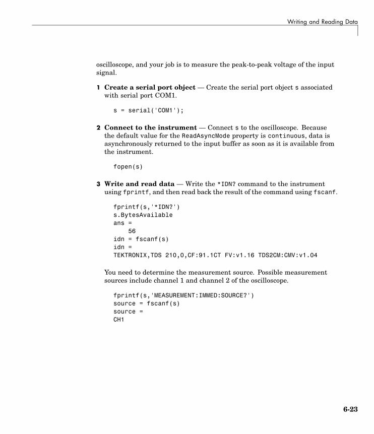
Writing and Reading Data
oscilloscope, and your job is to measure the peak-to-peak voltage of the inputsignal.
1 Create a serial port object — Create the serial port object s associatedwith serial port COM1.
s = serial('COM1');
2 Connect to the instrument — Connect s to the oscilloscope. Becausethe default value for the ReadAsyncMode property is continuous, data isasynchronously returned to the input buffer as soon as it is available fromthe instrument.
fopen(s)
3 Write and read data — Write the *IDN? command to the instrumentusing fprintf, and then read back the result of the command using fscanf.
fprintf(s,'*IDN?')s.BytesAvailableans =
56idn = fscanf(s)idn =TEKTRONIX,TDS 210,0,CF:91.1CT FV:v1.16 TDS2CM:CMV:v1.04
You need to determine the measurement source. Possible measurementsources include channel 1 and channel 2 of the oscilloscope.
fprintf(s,'MEASUREMENT:IMMED:SOURCE?')source = fscanf(s)source =CH1
6-23

6 Controlling Instruments Using the Serial Port
The scope is configured to return a measurement from channel 1. Becausethe input signal is connected to channel 2, you must configure theinstrument to return a measurement from this channel.
fprintf(s,'MEASUREMENT:IMMED:SOURCE CH2')fprintf(s,'MEASUREMENT:IMMED:SOURCE?')source = fscanf(s)source =CH2
You can now configure the scope to return the peak-to-peak voltage, andthen request the value of this measurement.
fprintf(s,'MEASUREMENT:MEAS1:TYPE PK2PK')fprintf(s,'MEASUREMENT:MEAS1:VALUE?')
Transfer data from the input buffer to MATLAB using fscanf.
ptop = fscanf(s)ptop =2.0199999809E0
4 Disconnect and clean up — When you no longer need s, you shoulddisconnect it from the instrument, and remove it from memory and fromthe MATLAB workspace.
fclose(s)delete(s)clear s
6-24

Events and Callbacks
Events and Callbacks
In this section...
“Event Types and Callback Properties” on page 6-25
“Storing Event Information” on page 6-26
“Example: Using Events and Callbacks” on page 6-28
Event Types and Callback PropertiesThe event types and associated callback properties supported by serial portobjects are listed below.
Serial Port Event Types and Callback Properties
Event Type Associated Properties
Break interrupt BreakInterruptFcn
BytesAvailableFcn
BytesAvailableFcnCount
Bytes available
BytesAvailableFcnMode
Error ErrorFcn
Output empty OutputEmptyFcn
Pin status PinStatusFcn
TimerFcnTimer
TimerPeriod
The break-interrupt and pin-status events are described below. For adescription of the other event types, refer to “Event Types and CallbackProperties” on page 4-29.
Break-Interrupt EventA break-interrupt event is generated immediately after a break interrupt isgenerated by the serial port. The serial port generates a break interrupt when
6-25

6 Controlling Instruments Using the Serial Port
the received data has been in an inactive state longer than the transmissiontime for one character.
This event executes the callback function specified for the BreakInterruptFcnproperty. It can be generated for both synchronous and asynchronous readand write operations.
Pin-Status EventA pin-status event is generated immediately after the state (pin value)changes for the CD, CTS, DSR, or RI pins. Refer to “Serial Port Signals andPin Assignments” on page 6-5 for a description of these pins.
This event executes the callback function specified for the PinStatusFcnproperty. It can be generated for both synchronous and asynchronous readand write operations.
Storing Event InformationYou can store event information in a callback function or in a record file. Eventinformation stored in a callback function uses two fields: Type and Data. TheType field contains the event type, while the Data field contains event-specificinformation. As described in “Creating and Executing Callback Functions” onpage 4-32, these two fields are associated with a structure that you define inthe callback function header. Refer to “Debugging: Recording Information toDisk” on page 12-6 to learn about storing event information in a record file.
The event types and the values for the Type and Data fields are given below.
Serial Port Event Information
Event Type Field Field Value
Type BreakInterruptBreak interrupt
Data.AbsTime day-month-yearhour:minute:second
Type BytesAvailableBytes available
Data.AbsTime day-month-yearhour:minute:second
6-26

Events and Callbacks
Serial Port Event Information (Continued)
Event Type Field Field Value
Type Error
Data.AbsTime day-month-yearhour:minute:second
Error
Data.Message An error string
Type OutputEmptyOutput empty
Data.AbsTime day-month-yearhour:minute:second
Type PinStatus
Data.AbsTime day-month-yearhour:minute:second
Data.Pin CarrierDetect,ClearToSend,DataSetReady, orRingIndicator
Pin status
Data.PinValue on or off
Type TimerTimer
Data.AbsTime day-month-yearhour:minute:second
The Data field values are as follows:
Field Name Value
AbsTime AbsTime is defined for all events, and indicates theabsolute time the event occurred. The absolute time isreturned using the MATLAB clock format.
Pin Pin is used by the pin status event to indicate if the CD,CTS, DSR, or RI pins changed state. Refer to “SerialPort Signals and Pin Assignments” on page 6-5 for adescription of these pins.
6-27

6 Controlling Instruments Using the Serial Port
Field Name Value
PinValue PinValue is used by the pin status event to indicate thestate of the CD, CTS, DSR, or RI pins. Possible valuesare on or off.
Message Message is used by the error event to store the descriptivemessage that is generated when an error occurs.
Example: Using Events and CallbacksThis example uses the M-file callback function instrcallback to displayevent-related information to the command line when a bytes-available eventor an output-empty event occurs:
1 Create an instrument object — Create the serial port object s associatedwith serial port COM1.
s = serial('COM1');
2 Connect to the instrument — Connect s to the Tektronix TDS 210oscilloscope. Because the default value for the ReadAsyncMode property iscontinuous, data is asynchronously returned to the input buffer as soon asit is available from the instrument.
fopen(s)
3 Configure properties — Configure s to execute the callback functioninstrcallback when a bytes-available event or an output-empty eventoccurs.
s.BytesAvailableFcnMode = 'terminator';s.BytesAvailableFcn = @instrcallback;s.OutputEmptyFcn = @instrcallback;
4 Write and read data — Write the RS232? command asynchronously tothe oscilloscope. This command queries the RS-232 settings and returns
6-28

Events and Callbacks
the baud rate, the software flow control setting, the hardware flow controlsetting, the parity type, and the terminator.
fprintf(s,'RS232?','async')
instrcallback is called after the RS232? command is sent, and when theterminator is read. The resulting displays are shown below.
OutputEmpty event occurred at 17:37:21 for the object:Serial-COM1.
BytesAvailable event occurred at 17:37:21 for the object:Serial-COM1.
Read the data from the input buffer.
out = fscanf(s)out =9600;0;0;NONE;LF
5 Disconnect and clean up — When you no longer need s, you shoulddisconnect it from the instrument, and remove it from memory and fromthe MATLAB workspace.
fclose(s)delete(s)clear s
For a general overview of events and callbacks, including how to create andexecute callback functions, refer to “Events and Callbacks” on page 4-28.
6-29

6 Controlling Instruments Using the Serial Port
Using Control Pins
In this section...
“Control Pins” on page 6-30
“Signaling the Presence of Connected Devices” on page 6-30
“Controlling the Flow of Data: Handshaking” on page 6-33
Control PinsAs described in “Serial Port Signals and Pin Assignments” on page 6-5, 9-pinserial ports include six control pins. The properties associated with the serialport control pins are as follows:
Serial Port Control Pin Properties
Property Name Description
DataTerminalReady Specify the state of the DTR pin.
FlowControl Specify the data flow control method to use.
PinStatus Indicate the state of the CD, CTS, DSR, and RI pins.
RequestToSend Specify the state of the RTS pin.
Signaling the Presence of Connected DevicesDTEs and DCEs often use the CD, DSR, RI, and DTR pins to indicate whethera connection is established between serial port devices. Once the connection isestablished, you can begin to write or read data.
You can monitor the state of the CD, DSR, and RI pins with the PinStatusproperty. You can specify or monitor the state of the DTR pin with theDataTerminalReady property.
The following example illustrates how these pins are used when two modemsare connected to each other.
6-30
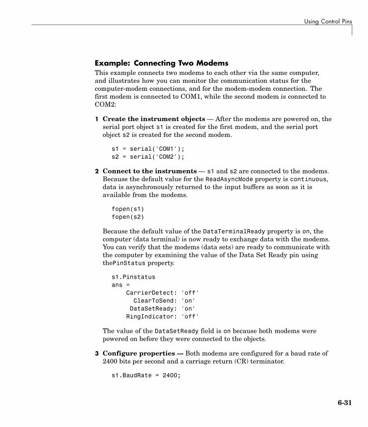
Using Control Pins
Example: Connecting Two ModemsThis example connects two modems to each other via the same computer,and illustrates how you can monitor the communication status for thecomputer-modem connections, and for the modem-modem connection. Thefirst modem is connected to COM1, while the second modem is connected toCOM2:
1 Create the instrument objects — After the modems are powered on, theserial port object s1 is created for the first modem, and the serial portobject s2 is created for the second modem.
s1 = serial('COM1');s2 = serial('COM2');
2 Connect to the instruments — s1 and s2 are connected to the modems.Because the default value for the ReadAsyncMode property is continuous,data is asynchronously returned to the input buffers as soon as it isavailable from the modems.
fopen(s1)fopen(s2)
Because the default value of the DataTerminalReady property is on, thecomputer (data terminal) is now ready to exchange data with the modems.You can verify that the modems (data sets) are ready to communicate withthe computer by examining the value of the Data Set Ready pin usingthePinStatus property.
s1.Pinstatusans =
CarrierDetect: 'off'ClearToSend: 'on'
DataSetReady: 'on'RingIndicator: 'off'
The value of the DataSetReady field is on because both modems werepowered on before they were connected to the objects.
3 Configure properties — Both modems are configured for a baud rate of2400 bits per second and a carriage return (CR) terminator.
s1.BaudRate = 2400;
6-31

6 Controlling Instruments Using the Serial Port
s1.Terminator = 'CR';s2.BaudRate = 2400;s2.Terminator = 'CR';
4 Write and read data — Write the atd command to the first modem. Thiscommand puts the modem “off the hook,” which is equivalent to manuallylifting a phone receiver.
fprintf(s1,'atd')
Write the ata command to the second modem. This command puts themodem in “answer mode,” which forces it to connect to the first modem.
fprintf(s2,'ata')
After the two modems negotiate their connection, you can verify theconnection status by examining the value of the Carrier Detect pin usingthe PinStatus property.
s1.PinStatusans =
CarrierDetect: 'on'ClearToSend: 'on'
DataSetReady: 'on'RingIndicator: 'off'
You can also verify the modem-modem connection by reading thedescriptive message returned by the second modem.
s2.BytesAvailableans =
25out = fread(s2,25);char(out)'ans =ataCONNECT 2400/NONE
Now break the connection between the two modems by configuring theDataTerminalReady property to off. You can verify that the modems aredisconnected by examining the Carrier Detect pin value.
6-32

Using Control Pins
s1.DataTerminalReady = 'off';s1.PinStatusans =
CarrierDetect: 'off'ClearToSend: 'on'
DataSetReady: 'on'RingIndicator: 'off'
5 Disconnect and clean up — Disconnect the objects from the modems,and remove the objects from memory and from the MATLAB workspace.
fclose([s1 s2])delete([s1 s2])clear s1 s2
Controlling the Flow of Data: HandshakingData flow control or handshaking is a method used for communicatingbetween a DCE and a DTE to prevent data loss during transmission. Forexample, suppose your computer can receive only a limited amount of databefore it must be processed. As this limit is reached, a handshaking signalis transmitted to the DCE to stop sending data. When the computer canaccept more data, another handshaking signal is transmitted to the DCE toresume sending data.
If supported by your device, you can control data flow using one of thesemethods:
• “Hardware Handshaking” on page 6-34
• “Software Handshaking” on page 6-34
Note Although you might be able to configure your device for both hardwarehandshaking and software handshaking at the same time, Instrument ControlToolbox does not support this behavior.
You can specify the data flow control method with the FlowControl property.If FlowControl is hardware, then hardware handshaking is used to control
6-33

6 Controlling Instruments Using the Serial Port
data flow. If FlowControl is software, then software handshaking is used tocontrol data flow. If FlowControl is none, then no handshaking is used.
Hardware HandshakingHardware handshaking uses specific serial port pins to control data flow. Inmost cases, these are the RTS and CTS pins. Hardware handshaking usingthese pins is described in “The RTS and CTS Pins” on page 6-8.
If FlowControl is hardware, then the RTS and CTS pins are automaticallymanaged by the DTE and DCE. You can return the CTS pin value with thePinStatus property. You can configure or return the RTS pin value withthe RequestToSend property.
Note Some devices also use the DTR and DSR pins for handshaking.However, these pins are typically used to indicate that the system is ready forcommunication, and are not used to control data transmission. For InstrumentControl Toolbox, hardware handshaking always uses the RTS and CTS pins.
If your device does not use hardware handshaking in the standard way, thenyou might need to manually configure the RequestToSend property. In thiscase, you should configure FlowControl to none. If FlowControl is hardware,then the RequestToSend value that you specify might not be honored. Referto the device documentation to determine its specific pin behavior.
Software HandshakingSoftware handshaking uses specific ASCII characters to control data flow.These characters, known as Xon and Xoff (or XON and XOFF), are describedbelow.
6-34

Using Control Pins
Software Handshaking Characters
Character Integer Value Description
Xon 17 Resume data transmission.
Xoff 19 Pause data transmission.
When using software handshaking, the control characters are sent over thetransmission line the same way as regular data. Therefore you need onlythe TD, RD, and GND pins.
The main disadvantage of software handshaking is that you cannot writethe Xon or Xoff characters while numerical data is being written to theinstrument. This is because numerical data might contain a 17 or 19, whichmakes it impossible to distinguish between the control characters and thedata. However, you can write Xon or Xoff while data is being asynchronouslyread from the instrument because you are using both the TD and RD pins.
Example: Using Software Handshaking. Suppose you want to usesoftware flow control in conjunction with your serial port application. To dothis, you must configure the instrument and the serial port object for softwareflow control. For a serial port object s connected to a Tektronix TDS 210oscilloscope, this configuration is accomplished with the following commands.
fprintf(s,'RS232:SOFTF ON')s.FlowControl = 'software';
To pause data transfer, you write the numerical value 19 (Xoff) to theinstrument.
fwrite(s,19)
To resume data transfer, you write the numerical value 17 (Xon) to theinstrument.
fwrite(s,17)
6-35

6 Controlling Instruments Using the Serial Port
6-36

7
Controlling InstrumentsUsing TCP/IP and UDP
This chapter describes specific features related to controlling instrumentsthat use the TCP/IP or UDP protocols.
TCP/IP and UDP Overview (p. 7-2) A comparison between the TCP/IPand UDP protocols.
Creating a TCP/IP Object (p. 7-4) The TCP/IP object establishes aconnection between MATLAB andthe remote host.
Creating an UDP Object (p. 7-10) The UDP object establishes aconnection between MATLAB andthe remote host.
Writing and Reading Data (p. 7-14) Interface-specific issues related towriting and reading data with aTCP/IP or UDP object.
Events and Callbacks (p. 7-21) Enhance your instrument controlapplication using events andcallbacks.

7 Controlling Instruments Using TCP/IP and UDP
TCP/IP and UDP OverviewTransmission Control Protocol (TCP or TCP/IP) and User Datagram Protocol(UDP or UDP/IP) are both transport protocols layered on top of the InternetProtocol (IP). TCP/IP and UDP are compared below:
• Connection Versus Connectionless — TCP/IP is a connection-basedprotocol, while UDP is a connectionless protocol. In TCP/IP, the two endsof the communication link must be connected at all times during thecommunication. An application using UDP prepares a packet and sendsit to the receiver’s address without first checking to see if the receiver isready to receive a packet. If the receiving end is not ready to receive apacket, the packet is lost.
• Stream Versus Packet — TCP/IP is a stream-oriented protocol, whileUDP is a packet-oriented protocol. This means that TCP/IP is consideredto be a long stream of data that is transmitted from one end of theconnection to the other end, and another long stream of data flowing inthe opposite direction. The TCP/IP stack is responsible for breaking thestream of data into packets and sending those packets while the stackat the other end is responsible for reassembling the packets into a datastream using information in the packet headers. UDP, on the other hand, isa packet-oriented protocol where the application itself divides the data intopackets and sends them to the other end. The other end does not have toreassemble the data into a stream. Note, some applications might presentthe data as a stream when the underlying protocol is UDP. However, this isthe layering of an additional protocol on top of UDP, and it is not somethinginherent in the UDP protocol itself.
• TCP/IP Is a Reliable Protocol, While UDP Is Unreliable — Thepackets that are sent by TCP/IP contain a unique sequence number.The starting sequence number is communicated to the other side at thebeginning of communication. The receiver acknowledges each packet, andthe acknowledgment contains the sequence number so that the senderknows which packet was acknowledged. This implies that any packets loston the way can be retransmitted (the sender would know that they did notreach their destination because it had not received an acknowledgment).Also, packets that arrive out of sequence can be reassembled in the properorder by the receiver.
7-2

TCP/IP and UDP Overview
Further, timeouts can be established because the sender knows (from thefirst few packets) how long it takes on average for a packet to be sent andits acknowledgment received. UDP, on the other hand, sends the packetsand does not keep track of them. Thus, if packets arrive out of sequence,or are lost in transmission, the receiving end (or the sending end) has noway of knowing.
Note that “unreliable” is used in the sense of “not guaranteed to succeed” asopposed to “will fail a lot of the time.” In practice, UDP is quite reliable as longas the receiving socket is active and is processing data as quickly as it arrives.
7-3

7 Controlling Instruments Using TCP/IP and UDP
Creating a TCP/IP Object
In this section...
“TCP/IP Object” on page 7-4
“TCP/IP Object Display” on page 7-5
“Example: Communicating with a Remote Host” on page 7-6
“Example: Server Drops the Connection” on page 7-7
TCP/IP ObjectYou create a TCP/IP object with the tcpip function. tcpip requires the nameof the remote host as an input argument. In most cases, you need to specifythe remote port value. If you do not specify the remote port, then 80 is used.As described in “Configuring Properties During Object Creation” on page 3-3,you can also configure property values during object creation.
Each TCP/IP object is associated with one instrument. For example, to createa TCP/IP object for a Sony/Tektronix AWG520 Arbitrary Waveform Generator,
t = tcpip('sonytekawg.mathworks.com',4000);
Note that the port number is fixed and is found in the instrument’sdocumentation.
The TCP/IP object t now exists in the MATLAB workspace. You can displaythe class of t with the whos command.
whos tName Size Bytes Class
t 1x1 640 tcpip object
Grand total is 16 elements using 640 bytes
Once the TCP/IP object is created, the following properties are automaticallyassigned values. These general-purpose properties provide information aboutthe TCP/IP object based on the object type, the remote host, and the remoteport.
7-4

Creating a TCP/IP Object
TCP/IP Descriptive Properties
Property Name Description
Name Specify a descriptive name for the TCP/IP object.
RemoteHost Specify the remote host.
RemotePort Specify the remote host port for the connection.
Type Indicate the object type.
You can display the values of these properties for t with the get function.
get(t,{'Name','RemoteHost','RemotePort','Type'})ans =
[1x31 char] [1x24 char] [4000] 'tcpip'
TCP/IP Object DisplayThe TCP/IP object provides you with a convenient display that summarizesimportant configuration and state information. You can invoke the displaysummary these three ways:
• Type the TCP/IP object variable name at the command line.
• Exclude the semicolon when creating a TCP/IP object.
• Exclude the semicolon when configuring properties using the dot notation.
You can also display summary information via the Workspace browser byright-clicking an instrument object and selecting Display Summary fromthe context menu.
The display summary for the TCP/IP object t is given below.
TCP/IP Object : TCP/IP-sonytekawg.mathworks.com
Communication SettingsRemotePort: 4000RemoteHost: sonytekawg.mathworks.comTerminator: 'LF'
Communication State
7-5
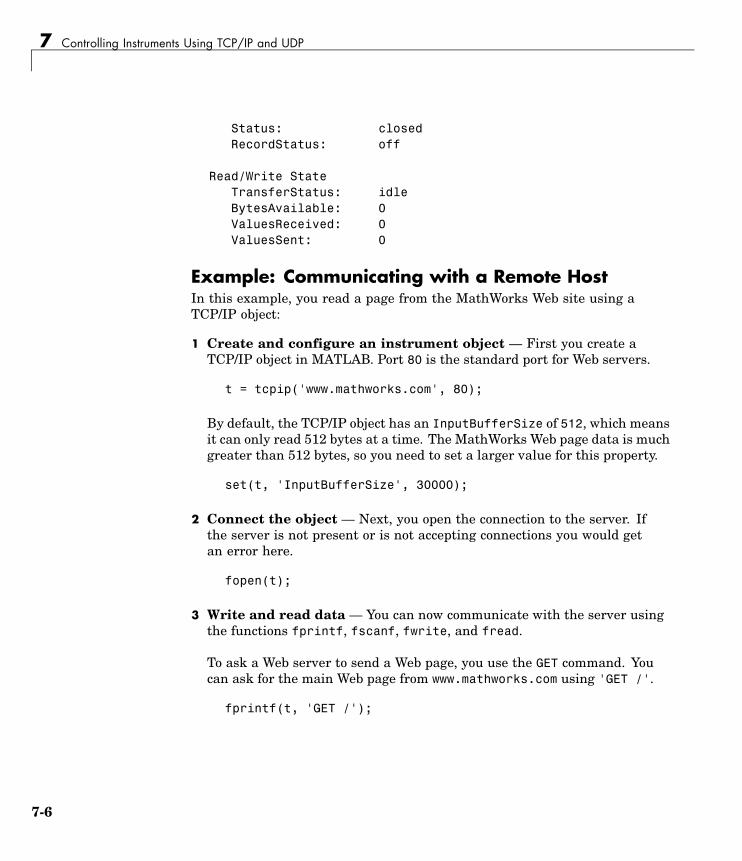
7 Controlling Instruments Using TCP/IP and UDP
Status: closedRecordStatus: off
Read/Write StateTransferStatus: idleBytesAvailable: 0ValuesReceived: 0ValuesSent: 0
Example: Communicating with a Remote HostIn this example, you read a page from the MathWorks Web site using aTCP/IP object:
1 Create and configure an instrument object — First you create aTCP/IP object in MATLAB. Port 80 is the standard port for Web servers.
t = tcpip('www.mathworks.com', 80);
By default, the TCP/IP object has an InputBufferSize of 512, which meansit can only read 512 bytes at a time. The MathWorks Web page data is muchgreater than 512 bytes, so you need to set a larger value for this property.
set(t, 'InputBufferSize', 30000);
2 Connect the object — Next, you open the connection to the server. Ifthe server is not present or is not accepting connections you would getan error here.
fopen(t);
3 Write and read data — You can now communicate with the server usingthe functions fprintf, fscanf, fwrite, and fread.
To ask a Web server to send a Web page, you use the GET command. Youcan ask for the main Web page from www.mathworks.com using 'GET /'.
fprintf(t, 'GET /');
7-6

Creating a TCP/IP Object
The server receives the command and sends back the Web page. You cansee if any data was sent back by looking at the BytesAvailable propertyof the object.
get(t, 'BytesAvailable')
Now you can start to read the Web page data. By default, fscanf reads oneline at a time. You can read lines of data until the BytesAvailable valueis 0. Note that you will not see a rendered web page; the HTML file datawill scroll by on the screen.
while (get(t, 'BytesAvailable') > 0)A = fscanf(t),
end
4 Disconnect and clean up — If you want to do more communication, youcan continue to read and write data here. If you are done with the object,close it and delete it.
fclose(t);delete(t);clear t
Example: Server Drops the ConnectionThis example shows what happens when a TCP/IP object loses its connectionwith a remote server. The server is a Sony/Tektronix AWG520 ArbitraryWaveform Generator (AWG). Its address is sonytekawg.mathworks.comand its port is 4000. The AWG’s host IP address is 192.168.1.10 and isuser configurable in the instrument. The associated host name is given byyour network administrator. The port number is fixed and is found in theinstrument’s documentation.
The AWG can drop the connection because it is taken off line, it is powereddown, and so on:
1 Create an instrument object — Create a TCP/IP object for the AWG.
t = tcpip('sonytekawg.mathworks.com', 4000);
2 Connect to the instrument — Connect to the remote instrument.
7-7

7 Controlling Instruments Using TCP/IP and UDP
fopen(t)
3 Write and read data — Write a command to the instrument and readback the result.
fprintf(t,'*IDN?')fscanf(t)ans =SONY/TEK,AWG520,0,SCPI:95.0 OS:2.0 USR:2.0
Assume that the server drops the connection. If you attempt to read fromthe instrument, a timeout occurs and a warning is displayed.
fprintf(t,'*IDN?')fscanf(t)
Warning: A timeout occurred before the Terminator was reached.(Type "warning off instrument:fscanf:unsuccessfulRead" tosuppress this warning.)ans =
''
At this point, the object and the instrument are still connected.
get(t,'Status')ans =open
If you attempt to write to the instrument again, an error message isreturned and the connection is automatically closed.
fprintf(t,'*IDN?')??? Error using ==> fprintfConnection closed by RemoteHost. Use FOPEN to connect toRemoteHost.
Note that if the TCP/IP object is connected to the local host, the warningmessage is not displayed. Instead, the error message is displayed followingthe next read operation after the connection is dropped.
7-8

Creating a TCP/IP Object
4 Disconnect and clean up — When you no longer need t, you shoulddisconnect it from the host, and remove it from memory and from theMATLAB workspace.
fclose(t)delete(t)clear t
7-9

7 Controlling Instruments Using TCP/IP and UDP
Creating an UDP Object
In this section...
“UDP Object” on page 7-10
“The UDP Object Display” on page 7-11
“Example: Communicating Between Two Hosts” on page 7-12
UDP ObjectYou create a UDP object with the udp function. udp does not require the nameof the remote host as an input argument. However, if you are using the objectto communicate with a specific instrument, you should specify the remotehost and the port number. As described in “Configuring Properties DuringObject Creation” on page 3-3, you can also configure property values duringobject creation, such as the LocalPort property if you will use the object toread data from the instrument.
For example, to create a UDP object associated with the remote host 127.0.0.1,remote port 4012, and local port 3533,
u = udp('127.0.0.1', 4012, 'LocalPort', 3533);
The UDP object u now exists in the MATLAB workspace. You can display theclass of u with the whos command.
whos uName Size Bytes Class
u 1x1 632 udp object
Grand total is 12 elements using 632 bytes
When the UDP object is created, the following properties are assigned valuesbased on the values provided to the upd function. These general purposeproperties provide information about the UDP object.
7-10

Creating an UDP Object
UDP Descriptive Properties
Property Name Description
Name Specify a descriptive name for the UDP object.
RemoteHost Specify the remote host.
RemotePort Specify the remote host port for the connection.
Type Indicate the object type.
LocalPort Specify the local host port, if you are expecting toreceive data from the instrument.
You can display the values of these properties for u with the get function.
get(u,{'Name','RemoteHost','RemotePort','Type','LocalPort'})ans =
'UDP-127.0.0.1' '127.0.0.1' [4012] 'udp' [3533]
The UDP Object DisplayThe UDP object provides you with a convenient display that summarizesimportant configuration and state information. You can invoke the displaysummary these three ways:
• Type the UDP object variable name at the command line.
• Exclude the semicolon when creating a UDP object.
• Exclude the semicolon when configuring properties using the dot notation.
You can also display summary information via the Workspace browser byright-clicking an instrument object and selecting Display Summary fromthe context menu.
The display summary for the UDP object u is given below.
UDP Object : UDP-127.0.0.1
Communication SettingsRemotePort: 4012RemoteHost: 127.0.0.1
7-11
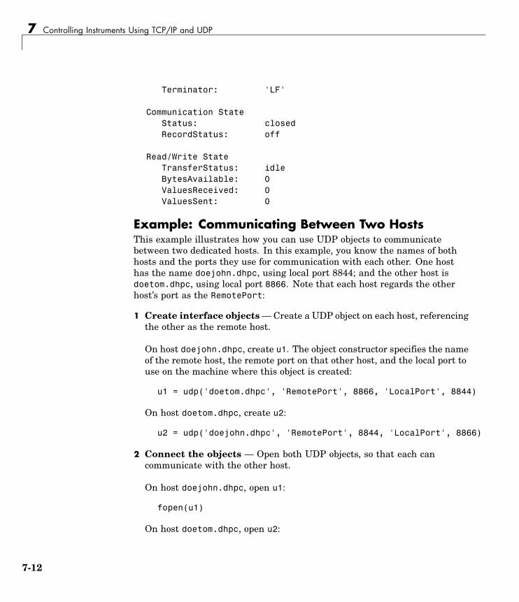
7 Controlling Instruments Using TCP/IP and UDP
Terminator: 'LF'
Communication StateStatus: closedRecordStatus: off
Read/Write StateTransferStatus: idleBytesAvailable: 0ValuesReceived: 0ValuesSent: 0
Example: Communicating Between Two HostsThis example illustrates how you can use UDP objects to communicatebetween two dedicated hosts. In this example, you know the names of bothhosts and the ports they use for communication with each other. One hosthas the name doejohn.dhpc, using local port 8844; and the other host isdoetom.dhpc, using local port 8866. Note that each host regards the otherhost’s port as the RemotePort:
1 Create interface objects — Create a UDP object on each host, referencingthe other as the remote host.
On host doejohn.dhpc, create u1. The object constructor specifies the nameof the remote host, the remote port on that other host, and the local port touse on the machine where this object is created:
u1 = udp('doetom.dhpc', 'RemotePort', 8866, 'LocalPort', 8844)
On host doetom.dhpc, create u2:
u2 = udp('doejohn.dhpc', 'RemotePort', 8844, 'LocalPort', 8866)
2 Connect the objects — Open both UDP objects, so that each cancommunicate with the other host.
On host doejohn.dhpc, open u1:
fopen(u1)
On host doetom.dhpc, open u2:
7-12

Creating an UDP Object
fopen(u2)
3 Write and read data — Communication between the two hosts is now amatter of sending and receiving data. Write a message from doejohn.dhpcto doetom.dhpc.
On host doejohn.dhpc, write data to the remote host via u1:
fprintf(u1, 'Ready for data transfer.')
On host doetom.dhpc, read data coming in from the remote host via u2:
fscanf(u2)ans =Ready for data transfer.
4 Disconnect and clean up — When you no longer need u1 on hostdoejohn.dhpc, you should disconnect it and remove it from memory andfrom the MATLAB workspace.
fclose(u1)delete(u1)clear u1
When you no longer need u2, perform a similar cleanup on the hostdoetom.dhpc.
fclose(u2)delete(u2)clear u2
7-13

7 Controlling Instruments Using TCP/IP and UDP
Writing and Reading Data
In this section...
“Rules for Completing Write and Read Operations” on page 7-14
“Example: Writing and Reading Data with a TCP/IP Object” on page 7-15
“Example: Writing and Reading Data with a UDP Object” on page 7-18
Rules for Completing Write and Read OperationsThe rules for completing synchronous and asynchronous read and writeoperations are described below.
For a general overview about writing and reading data, as well as a list ofall associated functions and properties, refer to “Communicating with YourInstrument” on page 2-7.
Completing Write OperationsA write operation using fprintf or fwrite completes when one of theseconditions is satisfied:
• The specified data is written.
• The time specified by the Timeout property passes.
In addition to these rules, you can stop an asynchronous write operation atany time with the stopasync function.
A text command is processed by the instrument only when it receives therequired terminator. For TCP/IP and UDP objects, each occurrence of \nin the ASCII command is replaced with the Terminator property value.Because the default format for fprintf is %s\n, all commands written tothe instrument will end with the Terminator value. The default value ofTerminator is the line feed character. The terminator required by yourinstrument will be described in its documentation.
7-14

Writing and Reading Data
Completing Read OperationsA read operation with fgetl, fgets, fscanf, or readasync completes whenone of these conditions is satisfied:
• The terminator specified by the Terminator property is read. For UDPobjects, DatagramTerminateMode must be off.
• The time specified by the Timeout property passes.
• The input buffer is filled.
• The specified number of values is read (fscanf and readasync only). ForUDP objects, DatagramTerminateMode must be off.
• A datagram is received (for UDP objects, only whenDatagramTerminateMode is on).
A read operation with fread completes when one of these conditions issatisfied:
• The time specified by the Timeout property passes.
• The input buffer is filled.
• The specified number of values is read. For UDP objects,DatagramTerminateMode must be off.
• A datagram is received (for UDP objects, only whenDatagramTerminateMode is on).
In addition to these rules, you can stop an asynchronous read operation atany time with the stopasync function.
Example: Writing and Reading Data with a TCP/IPObjectThis example illustrates how to use text and binary read and write operationswith a TCP/IP object connected to a remote instrument. In this example,you create a vector of waveform data in MATLAB, upload the data to theinstrument, and then read back the waveform.
The instrument is a Sony/Tektronix AWG520 Arbitrary Waveform Generator(AWG). Its address is sonytekawg.mathworks.com and its port is 4000.
7-15

7 Controlling Instruments Using TCP/IP and UDP
The AWG’s host IP address is 192.168.1.10 and is user configurable in theinstrument. The associated host name is given by your network administrator.The port number is fixed and is found in the instrument’s documentation:
1 Create an instrument object — Create a TCP/IP object associated withthe AWG.
t = tcpip('sonytekawg.mathworks.com',4000);
2 Connect to the instrument — Before establishing a connection, theOutputBufferSize must be large enough to hold the data being written.In this example, 2577 bytes are written to the instrument. Therefore, theOutputBufferSize is set to 3000.
set(t,'OutputBufferSize',3000)
You can now connect t to the instrument.
fopen(t)
3 Write and read data — Since the instrument’s byte order is little-endian,configure the ByteOrder property to littleEndian.
set(t,'ByteOrder','littleEndian')
Create the sine wave data.
x = (0:499).*8*pi/500;data = sin(x);marker = zeros(length(data),1);marker(1) = 3;
Instruct the instrument to write the file sin.wfm with Waveform Fileformat, a total length of 2544 bytes, and a combined data and markerlength of 2500 bytes.
fprintf(t,'%s',['MMEMORY:DATA "sin.wfm",#42544MAGIC 1000' 13 10])fprintf(t,'%s','#42500')
7-16

Writing and Reading Data
Write the sine wave to the instrument.
for (i = 1:length(data)),fwrite(t,data(i),'float32');fwrite(t,marker(i));
end
Instruct the instrument to use a clock frequency of 100 MS/s for thewaveform.
fprintf(t,'%s',['CLOCK 1.0000000000e+008' 13 10 10])
Read the waveform stored in the function generator’s hard drive. Thewaveform contains 2000 bytes plus markers, header, and clock information.To store this data, close the connection and configure the input buffer tohold 3000 bytes.
fclose(t)set(t,'InputBufferSize',3000)
Reopen the connection to the instrument.
fopen(t)
Read the file sin.wfm from the function generator.
fprintf(t,'MMEMORY:DATA? "sin.wfm" ')data = fread(t,t.BytesAvailable);
The next set of commands reads the same waveform as a float32 array. Tobegin, write the waveform to the AWG.
fprintf(t,'MMEMORY:DATA? "sin.wfm" ')
Read the file header as ASCII characters.
header1 = fscanf(t)header1 =#42544MAGIC 1000
7-17
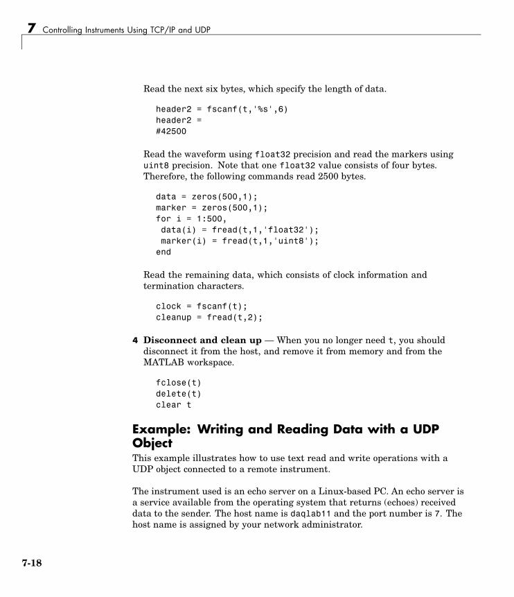
7 Controlling Instruments Using TCP/IP and UDP
Read the next six bytes, which specify the length of data.
header2 = fscanf(t,'%s',6)header2 =#42500
Read the waveform using float32 precision and read the markers usinguint8 precision. Note that one float32 value consists of four bytes.Therefore, the following commands read 2500 bytes.
data = zeros(500,1);marker = zeros(500,1);for i = 1:500,data(i) = fread(t,1,'float32');marker(i) = fread(t,1,'uint8');
end
Read the remaining data, which consists of clock information andtermination characters.
clock = fscanf(t);cleanup = fread(t,2);
4 Disconnect and clean up — When you no longer need t, you shoulddisconnect it from the host, and remove it from memory and from theMATLAB workspace.
fclose(t)delete(t)clear t
Example: Writing and Reading Data with a UDPObjectThis example illustrates how to use text read and write operations with aUDP object connected to a remote instrument.
The instrument used is an echo server on a Linux-based PC. An echo server isa service available from the operating system that returns (echoes) receiveddata to the sender. The host name is daqlab11 and the port number is 7. Thehost name is assigned by your network administrator.
7-18

Writing and Reading Data
1 Create an instrument object — Create a UDP object associated withdaqlab11.
u = udp('daqlab11',7);
2 Connect to the instrument — Connect u to the echo server.
fopen(u)
3 Write and read data — You use the fprintf function to write text data tothe instrument. For example, write the following string to the echo server.
fprintf(u,'Request Time')
UDP sends and receives data in blocks that are called datagrams. Eachtime you write or read data with a UDP object, you are writing or readinga datagram. For example, the string sent to the echo server constitutes adatagram with 13 bytes — 12 ASCII bytes plus the line feed terminator.
You use the fscanf function to read text data from the echo server.
fscanf(u)ans =Request Time
The DatagramTerminateMode property indicates whether a readoperation terminates when a datagram is received. By default,DatagramTerminateMode is on and a read operation terminates when adatagram is received. To return multiple datagrams in one read operation,set DatagramTerminateMode to off.
The following commands write two datagrams. Note that only the seconddatagram sends the terminator character.
fprintf(u,'%s','Request Time')fprintf(u,'%s\n','Request Time')
7-19

7 Controlling Instruments Using TCP/IP and UDP
Since DatagramTerminateMode is off, fscanf reads across datagramboundaries until the terminator character is received.
set(u,'DatagramTerminateMode','off')data = fscanf(u)data =Request TimeRequest Time
4 Disconnect and clean up — When you no longer need u, you shoulddisconnect it from the host, and remove it from memory and from theMATLAB workspace.
fclose(u)delete(u)clear u
7-20
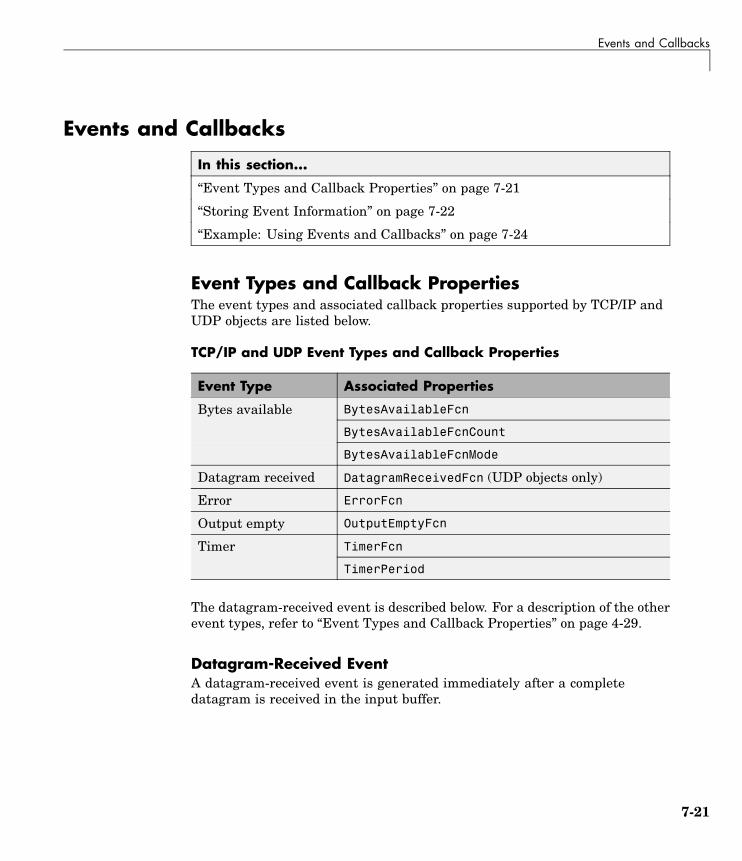
Events and Callbacks
Events and Callbacks
In this section...
“Event Types and Callback Properties” on page 7-21
“Storing Event Information” on page 7-22
“Example: Using Events and Callbacks” on page 7-24
Event Types and Callback PropertiesThe event types and associated callback properties supported by TCP/IP andUDP objects are listed below.
TCP/IP and UDP Event Types and Callback Properties
Event Type Associated Properties
BytesAvailableFcn
BytesAvailableFcnCount
Bytes available
BytesAvailableFcnMode
Datagram received DatagramReceivedFcn (UDP objects only)
Error ErrorFcn
Output empty OutputEmptyFcn
TimerFcnTimer
TimerPeriod
The datagram-received event is described below. For a description of the otherevent types, refer to “Event Types and Callback Properties” on page 4-29.
Datagram-Received EventA datagram-received event is generated immediately after a completedatagram is received in the input buffer.
7-21

7 Controlling Instruments Using TCP/IP and UDP
This event executes the callback function specified for theDatagramReceivedFcn property. It can be generated for both synchronousand asynchronous read operations.
Storing Event InformationYou can store event information in a callback function or in a record file. Eventinformation stored in a callback function uses two fields: Type and Data. TheType field contains the event type, while the Data field contains event-specificinformation. As described in “Creating and Executing Callback Functions” onpage 4-32, these two fields are associated with a structure that you define inthe callback function header. Refer to “Debugging: Recording Information toDisk” on page 12-6 to learn about storing event information in a record file.
The event types and the values for the Type and Data fields are given below.
TCP/IP and UDP Event Information
Event Type Field Field Value
Type BytesAvailableBytes available
Data.AbsTime day-month-yearhour:minute:second
Type DatagramReceived
Data.AbsTime day-month-yearhour:minute:second
Data.DatagramAddress IP address string
Data.DatagramLength Number of bytes received asdouble
Datagram received
Data.DatagramPort Port number of sender as double
Type Error
Data.AbsTime day-month-yearhour:minute:second
Error
Data.Message An error string
7-22

Events and Callbacks
TCP/IP and UDP Event Information (Continued)
Event Type Field Field Value
Type OutputEmptyOutput empty
Data.AbsTime day-month-yearhour:minute:second
Type TimerTimer
Data.AbsTime day-month-yearhour:minute:second
The Data field values are described below.
The AbsTime FieldAbsTime is defined for all events, and indicates the absolute time the eventoccurred. The absolute time is returned using the MATLAB clock format.
day-month-year hour:minute:second
The DatagramAddress FieldDatagramAddress is the IP address of the datagram sender.
The DatagramLength FieldDatagramLength is the length of the datagram in bytes.
The DatagramPort FieldDatagramPort is the sender’s port number from which the datagramoriginated.
The Message FieldMessage is used by the error event to store the descriptive message that isgenerated when an error occurs.
7-23

7 Controlling Instruments Using TCP/IP and UDP
Example: Using Events and CallbacksThis example extends “Example: Communicating Between Two Hosts” onpage 7-12 to include a datagram received callback. The callback function isinstrcallback, which displays information to the command line indicatingthat a datagram has been received.
The following command configures the callback for the UDP object u2.
u2.DatagramReceivedFcn = @instrcallback;
When a datagram is received, the following message is displayed.
DatagramReceived event occurred at 10:26:20 for the object:UDP-doetom.dhpc.25 bytes were received from address 192.168.1.12, port 8844.
7-24

8
Using Device Objects
This chapter describes specific features and actions related to using deviceobjects. The sections are as follows.
Device Objects (p. 8-2) Basic features of device objects
Creating and Connecting DeviceObjects (p. 8-5)
General procedure for the creationand use of device objects
Communicating with Instruments(p. 8-9)
Object-specific issues related toconfiguring and exchanging datathrough device objects
Device Groups (p. 8-14) Obtaining and using group deviceproperties
8 Using Device Objects
Device Objects
In this section...
“Device Objects: Overview” on page 8-2
“What Are Device Objects?” on page 8-2
“Device Objects for MATLAB Instrument Drivers” on page 8-3
Device Objects: OverviewAll instruments attached to your computer must communicate throughan interface. Popular interface protocols include GPIB, VISA, and RS-232(serial). While Instrument Control interface objects allow you to communicatewith your equipment at a low (instrument command) level, InstrumentControl Toolbox also allows you to communicate with your equipment withoutdetailed knowledge of how the hardware interface operates.
Programmable devices understand a specific language, sometimes referred toas its command set. One common set is called SCPI (Standard Commands forProgrammable Instruments).
Device objects allow you to configure and query an instrument withoutknowledge of its command set. This chapter covers the basic functionality ofdevice objects that use MATLAB instrument drivers.
If your application is straightforward, or if you are already familiar withthe topics mentioned above, you might want to begin with “Creating andConnecting Device Objects” on page 8-5. If you want a high-level descriptionof all the steps you are likely to take when communicating with yourinstrument, refer to Chapter 2, “The Instrument Control Session”.
What Are Device Objects?Device objects are used to represent instruments in MATLAB. Properties andmethods specific to an instrument are encapsulated within device objects.Device objects also free you from the specific underlying commands requiredto communicate with your hardware.
8-2

Device Objects
You can use device objects at the MATLAB command prompt, insideM-Functions, M-Scripts, and graphical user interface callbacks. The low-levelcommunication is performed through a MATLAB instrument driver.
����
������� �
� ��������
������������
��������������
������
���������
������������������
���������������
���
!��
�"��
�
#����$
�%�
��%��%
��%
!���"�������������
����
Device Objects for MATLAB Instrument DriversThere are three types of MATLAB instrument drivers:
• MATLAB interface instrument driver
• MATLAB IVI instrument driver
• MATLAB VXIplug&play instrument driver
• Generic instrument driver
Instrument Control Toolbox device objects support all these types of MATLABdrivers, so that by using a device object, you can interface with any of thesedrivers in the same way. However, each of these drivers interfaces differentlywith the hardware. While MATLAB IVI and MATLAB VXIplug&playdrivers interface directly through standard drivers and the hardware portto the instrument, the MATLAB interface driver requires an interfaceobject to communicate with the instrument. You can use generic drivers tocommunicate with devices or software. For more information on genericdrivers, see Chapter 11, “Using Generic Instrument Drivers”.
8-3

8 Using Device Objects
Instrument Control Toolbox supports the following interface objects:
• gpib
• serial
• tcpip
• udp
• visa
To learn how to create and use interface objects, see Chapter 3, “UsingInterface Objects”.
Note If you are using an interface object with a device object and a MATLABinterface driver, you do not need to connect the interface object to the interfaceusing the fopen command. You need to connect the device object only.
Available MATLAB Instrument DriversSeveral drivers ship with Instrument Control Toolbox. You can find thesedrivers by looking in the directory
matlabroot\toolbox\instrument\instrument\drivers
where matlabroot is the MATLAB installation directory, as seen when youtype
matlabroot
at the MATLAB command prompt.
Many other drivers are available on the MathWorks Web site at
http://www.mathworks.com/matlabcentral/fileexchange
including drivers specifically for Instrument Control Toolbox.
8-4

Creating and Connecting Device Objects
Creating and Connecting Device Objects
In this section...
“Device Objects for MATLAB Interface Drivers” on page 8-5
“Device Objects for VXIplug&play and IVI Drivers” on page 8-7
“Connecting the Device Object” on page 8-7
Device Objects for MATLAB Interface DriversCreate a MATLAB device object to communicate with a Tektronix TDS210 Oscilloscope. To communicate with the scope you will use a NationalInstruments GBIB controller.
1 First create an interface object for the GPIB hardware. The followingcommand creates a GPIB object for a National Instruments GPIB board atindex 0 with an instrument at primary address 1.
g = gpib('ni',0,1);
2 Now that you have created the interface object, you can construct a deviceobject that uses it. The command to use is icdevice. You need to supplythe name of the instrument driver, tektronix_tds210, and the interfaceobject created for the GPIB controller, g.
d = icdevice('tektronix_tds210', g);
You can use the whos command to display the size and class of d.
whos dName Size Bytes Class
d 1x1 652 icdevice object
Grand total is 22 elements using 652 bytes
Device Object PropertiesA device object has a set of base properties and a set of properties defined bythe driver. All device objects have the same base properties, regardless of the
8-5

8 Using Device Objects
driver being used. The driver properties are defined by the driver specifiedin the icdevice constructor.
You can display the current values of all properties for d with the getcommand.
get(d)
The Device Object DisplayDevice objects provide you with a convenient display that summarizesimportant object information. You can invoke the display in these ways:
• Type the name of the device object at the command line.
• Exclude the semicolon when creating the device object.
• Exclude the semicolon when configuring properties using dot notation.
• Pass the object to the disp or display function.
The display summary for device object d is given below.
Instrument Device Object Using Driver : tektronix_tds210.mdd
Instrument InformationType: OscilloscopeManufacturer: TektronixModel: TDS210
Driver InformationDriverType: MATLAB interface objectDriverName: tektronix_tds210.mddDriverVersion: 1.0
Communication StateStatus: open
You can also display summary information via the Workspace browser byright-clicking a device object and selecting Display Summary from thecontext menu.
8-6

Creating and Connecting Device Objects
Device Objects for VXIplug&play and IVI Drivers
Creating the MATLAB Instrument DriverThe command-line function makemid creates a MATLAB instrument driverfrom a VXIplug&play, IVI-C, or IVI-COM driver, saving the new driver ina file on disk. The syntax is
makemid('driver','filename')
where driver is the original VXIplug&play, IVI-C, or IVI-COM driver name(identified by instrhwinfo or the Test & Measurement Tool), and filenameis the file containing the newly created MATLAB instrument driver. See themakemid reference page for a full description of the function and all its options.
You can open the new driver in the MATLAB Instrument Driver Editor, andthen modify and save it as required.
Creating the Device ObjectAfter you create the MATLAB instrument driver by conversion, you create thedevice object with the filename of the new driver as an argument for icdevice.
For example, if the driver is created from a VXIplug&play, IVI-C, or directlyfrom an IVI-COM driver,
obj = icdevice('ConvertedDriver.mdd','GPIB0::2::INSTR')
If the driver is created from an IVI-COM logical name,
obj = icdevice('ConvertedDriver.mdd')
Connecting the Device ObjectNow that you have created the device object, you can connect it to theinstrument with the connect function. To connect the device object, d, createdin the last example, use the following command:
connect(d);
By default, the property settings are updated to reflect the current state ofthe instrument. You can modify the instrument settings to reflect the device
8-7

8 Using Device Objects
object’s property values by passing an optional update parameter to connect.The update parameter can be either object or instrument. To have theinstrument updated to the object’s property values, the connect functionfrom the previous example would be
connect(d, 'instrument');
If connect is successful, the device object’s status property is set to open;otherwise it remains as closed. You can check the status of this property withthe get function or by looking at the object display.
get(d, 'status')
ans =
open
8-8

Communicating with Instruments
Communicating with Instruments
In this section...
“Configuring Instrument Settings” on page 8-9
“Calling Device Object Methods” on page 8-10
“Control Commands” on page 8-12
Configuring Instrument SettingsOnce a device object has been created and connected, it can be used as theinterface to an instrument. This chapter shows you how to access andconfigure your instrument’s settings, as well as how to read and write data tothe instrument.
Every device object contains properties specific to the instrument it represents.These properties are defined by the instrument driver used during deviceobject creation. For example, there may be properties for an oscilloscope thatallow you to adjust trigger parameters, or the contrast of the screen display.
Properties are assigned default values at device object creation. On executionof connect the object is updated to reflect the state of the instrument or viceversa, depending on the second argument given to connect.
You can obtain a full listing of configurable properties by calling the setcommand and passing the device object.
Example: Configuring Settings on an OscilloscopeThis example illustrates how to configure an instrument using a device object.
The instrument used is a Tektronix TDS 210 two-channel oscilloscope. Asquare wave is input into channel 1 of the oscilloscope. The task is to adjustthe scope’s settings so that triggering occurs on the falling edge of the signal:
1 Create the device object — Create a GPIB interface object, and then adevice object for a TDS 210 oscilloscope.
g = gpib('ni',0,1);
8-9

8 Using Device Objects
d = icdevice('tektronix_tds210', g);
2 Connect the device object — Use the connect function to connect thedevice object to the instrument.
connect(d);
3 Check the current TriggerSlope settings — Use the get function toobtain the current value for the oscilloscope TriggerSlope property.
get(d, 'TriggerSlope')
ans =
rising
The TriggerSlope is currently set to rising.
4 Change the TriggerSlope setting — If you want triggering to occur onthe falling edge, you need to modify that setting in the device object. Thiscan be accomplished with the set command.
set(d, 'TriggerSlope', 'falling');
This changes TriggerSlope to falling.
5 Disconnect and clean up — When you no longer need the device object,disconnect it from the instrument and remove it from memory. Remove thedevice object and interface object from the MATLAB workspace.
disconnect(d);delete(d);clear d g;
Calling Device Object MethodsDevice objects contain methods specific to the instruments theyrepresent. Implementation details are hidden behind a single function.Instrument-specific functions are defined in the MATLAB instrument driver.
The methods function displays all available driver-defined functions for thedevice object. The display is divided into two sections:
8-10

Communicating with Instruments
• Generic object functions
• Driver-specific object functions
To view the available methods, type
methods(obj)
Use the instrhelp function to get help on the device object functions.
instrhelp(obj, methodname);
To call instrument-specific methods you use the invoke function. invokerequires the device object and the name of the function. You must also provideinput arguments, when appropriate. The following example demonstrateshow to use invoke to obtain measurement data from an oscilloscope.
Example: Using Device Object FunctionsThis example illustrates how to call an instrument-specific device objectfunction. Your task is to obtain the frequency measurement of a waveform.The instrument is a Tektronix TDS 210 two-channel oscilloscope.
The scope has been preconfigured with a square wave input into channel 1of the oscilloscope. The hardware supports four different measurements:frequency, mean, period, and peak-to-peak. The requested measurement issignified with the use of an index variable from 1 to 4.
For demonstration purposes, the oscilloscope in this example has beenpreconfigured with the correct measurement settings:
1 Create the device object — Create a GPIB interface object and a deviceobject for the oscilloscope.
g = gpib('ni',0,1);d = icdevice('tektronix_tds210', g);
2 Connect the device object — Use the connect command to open theGPIB object and update the settings in the device object.
connect(d);
8-11

8 Using Device Objects
3 Obtain the frequency measurement — Use the invoke command andcall measure. The measure function requires that an index parameterbe specified. The value of the index specifies which measurement theoscilloscope should return. For the current setup of the Tektronix TDS 210oscilloscope, an index of 1 indicates that frequency is to be measured.
invoke(d, 'measure', 1)
ans =
999.9609
The frequency returned is 999.96 Hz, or nearly 1 kHz.
4 Disconnect and clean up — You no longer need the device object so youcan disconnect it from the instrument. You should also delete it frommemory and remove it from the MATLAB workspace.
disconnect(d);delete(d);clear d g;
Control CommandsControl commands are special functions and properties that exist for all deviceobjects. You use control commands to identify an instrument, reset hardwaresettings, perform diagnostic routines, and retrieve instrument errors. Theset of control commands consists of
• “InstrumentModel” on page 8-13
• “devicereset” on page 8-13
• “selftest” on page 8-13
• “geterror” on page 8-13
All control commands are defined within the MATLAB instrument driverfor your device.
8-12

Communicating with Instruments
InstrumentModelInstrumentModel is a device object property. When queried, the instrumentidentification command is sent to the instrument.
For example, for a Tektronix TDS 210 oscilloscope,
get(d, 'InstrumentModel')
ans =
TEKTRONIX,TDS 210,0,CF:91.1CT FV:v2.03 TDS2MM:MMV:v1.04
deviceresetTo restore the factory settings on your instrument, use the deviceresetfunction. When devicereset is called, the appropriate reset instruction issent to your instrument.
The command accepts a connected device object and has no output arguments.
devicereset(obj);
selftestThis command requests that your instrument perform a self-diagnostic.The actual operations performed and output arguments are specific to theinstrument your device object is connected to. selftest accepts a connecteddevice object as an input argument.
result = selftest(obj);
geterrorYou can retrieve error messages generated by your instrument with thegeterror function. The returned messages are instrument specific. geterroraccepts a connected device object as an input argument.
msg = geterror(obj);
8-13
8 Using Device Objects
Device Groups
In this section...
“Working with Group Objects” on page 8-14
“Example: Using Device Groups to Access Instrument Data” on page 8-15
Working with Group ObjectsDevice groups are used to group several related properties. For example, achannel group might contain the input channels of an oscilloscope, and theproperties and methods specific to the input channels on the instrument.
MATLAB instrument drivers specify the type and quantity of device groupsfor device objects.
Group objects can be accessed via the get command. For the Tektronix TDS210 oscilloscope, there is a channel group that contains two group objects. Thedevice property to access a group is always the group name.
chans = get(d, 'Channel')
HwIndex: HwName: Type: Name:1 CH1 scope-channel Channel12 CH2 scope-channel Channel2
To display the functions that a device group object supports, use the methodsfunction.
methods(chans(1))
You can also display a list of the group object’s properties and their currentsettings with the get function.
get(chans(2))
To get help on a driver-specific property or function, use the instrhelpfunction, with the name of the function or property.
instrhelp(chans(1),'Coupling')
8-14

Device Groups
Example: Using Device Groups to Access InstrumentDataThis example shows how to obtain waveform data from a Tektronix TDS 210oscilloscope with a square wave signal input on channel 1, on a Windowsmachine. The methods used are specific to this instrument:
1 Create and connect — First, create the device object for the oscilloscopeand then connect to the instrument.
s = serial('com1');d = icdevice('tektronix_tds210', s);connect(d);
2 Get the device group — To retrieve waveform data, first gain access tothe Waveform group for the device object.
w = get(d, 'waveform');
This group is specific for the hardware you are using. The TDS 210oscilloscope has one Waveform; therefore the group contains one groupobject.
HwIndex: HwName: Type: Name:1 Waveform1 scope-waveform Waveform1
3 Obtain the waveform — Now that you have access to the Waveformgroup objects, you can call the readwaveform function to acquire the data.For this example, channel 1 of the oscilloscope is reading the signal. Toaccess this channel, call readwaveform on the first channel.
wave = invoke(w, 'readwaveform', 'channel1');
4 View the data — The wave variable now contains the waveform data fromthe oscilloscope. Use the plot command to view the data.
plot(wave);
5 Disconnect and clean up — Once the task is done, disconnect thehardware and free the memory used by the objects.
disconnect(d)delete([d s])
8-15

8 Using Device Objects
clear d, s, w, wave;
8-16

9
Using VXIplug&playDrivers
This chapter describes the use of VXIplug&play drivers for instrumentcontrol. The sections are as follows.
Overview (p. 9-2) Standard VXIplug&play drivers andthe configurations required for them.
VXIplug&play Drivers (p. 9-4) Determining whether your systemis configured to use VXIplug&playdrivers, creating MATLABVXIplug&play instrument drivers,and creating device objects.

9 Using VXIplug&play Drivers
Overview
In this section...
“The Instrument Control Toolbox and VXIplug&play Drivers ” on page 9-2
“VISA Setup” on page 9-2
“Other Software Requirements” on page 9-3
The Instrument Control Toolbox and VXIplug&playDriversInstrument Control Toolbox can communicate with hardware usingVXIplug&play drivers. Most often, the instrument manufacturers supplythese drivers.
For definitions and specifications of VXIplug&play drivers, see the Web site ofthe VXIplug&play Systems Alliance at http://www.vxipnp.org.
VISA SetupA system must have VISA installed in order for VXIplug&play drivers towork. The driver installer software might specify certain VISA or otherconnectivity requirements.
To determine whether your system is properly configured with the necessaryversion of VISA, at the MATLAB prompt, type:
instrhwinfo visaans =
InstalledAdaptors: {'agilent'}JarFileVersion: 'Version 2.0 (R14)'
The cell array returned for InstalledAdaptors indicates which VISAsoftware is installed. A 1x0 cell array indicates that no VISA is installed.Possible InstalledAdaptors values are agilent, tek, and ni.
If you do not have VISA installed, you need to install it. The softwareinstallation disk provided with your instrument might include VISA along
9-2

Overview
with the instrument’s VXIplug&play driver, or you might be able to downloadVISA from the instrument manufacturer’s Web site.
Other Software RequirementsAn instrument driver can have other software requirements in addition to orinstead of VISA. Consult the driver documentation. The installer softwareitself might specify these requirements.
9-3
9 Using VXIplug&play Drivers
VXIplug&play Drivers
In this section...
“Installing VXI plug&play Drivers” on page 9-4
“Creating a MATLAB VXIplug&play Instrument Driver” on page 9-5
“Constructing Device Objects Using a MATLAB VXIplug&play InstrumentDriver” on page 9-8
Installing VXI plug&play DriversThe VXIplug&play driver particular to a piece of equipment is usuallyprovided by the equipment manufacturer as either an installation disk or as aWeb download. Once the driver is installed, you can determine whether theconfiguration is visible to MATLAB by using the Test & Measurement Tool toview the current driver installations. Open the tool by typing:
tmtool
Expand the Instrument Drivers node and click VXIplug&play Drivers.Click the Scan button to update the display. All installed VXIplug&playdrivers will be listed.
Alternatively, you can use the MATLAB command-line function instrhwinfoto find out which drivers are installed.
9-4

VXIplug&play Drivers
instrhwinfo ('vxipnp')ans =
InstalledDrivers: {'tktds5k', 'ag3325b', 'hpe363xa'}VXIPnPRootPath: 'C:\VXIPNP\WINNT'
The cell array returned for InstalledDrivers contains the names of all theinstalled VXIplug&play drivers. The string returned for VXIPnPRootPathindicates where the drivers are installed.
Creating a MATLAB VXIplug&play Instrument DriverTo use a VXIplug&play driver with a device object, you must have a MATLABVXIplug&play instrument driver based upon the information in the originalVXIplug&play driver. The MATLAB VXIplug&play instrument driver,whether modified or not, acts as a wrapper to the VXIplug&play driver. Youcan download or create the MATLAB instrument driver.
Downloading a Driver from the MathWorks Web SiteYou might find an appropriate MATLAB driver wrapper for your instrumenton the MathWorks Web site, on the Supported Hardware page for InstrumentControl Toolbox, at
http://www.mathworks.com/products/supportedio.html?prodCode=IC
On this page, click the Instrument Drivers link. You then have a choice togo to the MATLAB Central File Exchange, where you can look for thedriver you need, or you can submit a request to the MathWorks for yourparticular driver with the Instrument Driver Request Form.
To use the downloaded MATLAB VXIplug&play driver, you must also havethe instrument’s VXIplug&play driver installed. This driver is probablyavailable from the instrument manufacturer’s Web site.
Creating a Driver with makemidThe command-line function makemid creates a MATLAB VXIplug&playinstrument driver from a VXIplug&play driver, saving the new driver in a fileon disk. The syntax is
makemid('driver','filename')
9-5

9 Using VXIplug&play Drivers
where driver is the original VXIplug&play instrument driver name(identified by instrhwinfo), and filename is the file containing the resultingMATLAB instrument driver. See the makemid reference page for details onthis function.
If you need to customize the driver, open the new driver in the MATLABInstrument Driver Editor, modify it as required, and save it.
Note When you create a MATLAB instrument driver based on aVXIplug&play driver, the original driver must remain installed on yoursystem for you to use the new MATLAB instrument driver.
Importing with the MATLAB Instrument Driver Editor (midedit)The MATLAB Instrument Driver Editor can import a VXIplug&play driver,thereby creating a MATLAB VXIplug&play instrument driver. You canevaluate or set the driver’s functions and properties, and you can save themodified MATLAB instrument driver for further use:
1 Open the MATLAB Instrument Driver Editor with midedit.
2 Select File > Import.
3 In the Import Driver dialog box, select the VXIplug&play driver that youwant to import and click Import.
The MATLAB Instrument Driver Editor loads the driver and displays thecomponents of the driver, as shown in the following figures.
9-6

VXIplug&play Drivers
MATLAB Instrument Driver Editor Showing tktds5k MATLAB InstrumentDriver Summary
tktds5k MATLAB Instrument Driver Display Group Functions
With the MATLAB Instrument Driver Editor, you can:
• Create, delete, modify, and rename properties, functions, or groups.
9-7

9 Using VXIplug&play Drivers
• Add M-code around instrument commands for analysis.
• Add create, connect, and disconnect code.
• Save the driver as a MATLAB VXIplug&play instrument driver.
For more information, see Chapter 14, “Using the Instrument Driver Editor”.
Note When you create a MATLAB instrument driver based on aVXIplug&play driver, the original driver must remain installed on yoursystem for you to use the new MATLAB instrument driver.
Constructing Device Objects Using a MATLABVXIplug&play Instrument DriverOnce you have the MATLAB VXIplug&play instrument driver, you create thedevice object with the file name of the driver and a VISA resource name asarguments for icdevice. For example:
obj = icdevice('MATLABVXIpnpDriver.mdd','GPIB0::2::INSTR')connect(obj)
See the icdevice reference page for full details about this function.
9-8

10
Using IVI Drivers
This chapter describes the use of IVI drivers for instrument control. Thesections are as follows.
IVI Drivers Overview (p. 10-2) VISA or other requirements for yoursystem to use IVI drivers.
IVI Drivers (p. 10-4) Examine your IVI driver installation.Create MATLAB IVI instrumentdrivers. Create device objects forMATLAB IVI instrument drivers.
IVI Configuration Store (p. 10-11) Examine and configure your IVIconfiguration store.

10 Using IVI Drivers
IVI Drivers Overview
In this section...
“Instrument Control Toolbox and IVI Drivers” on page 10-2
“VISA Setup” on page 10-2
“IVI Shared Components” on page 10-3
“IVI Configuration Store Overview” on page 10-3
Instrument Control Toolbox and IVI DriversInstrument Control Toolbox can communicate with instruments usingInterchangeable Virtual Instrument (IVI) drivers. The toolbox supports bothIVI-C and IVI-COM drivers, provided by various instrument manufacturers.
For definitions and specifications of IVI drivers and their components, see theWeb site of the IVI Foundation at http://www.ivifoundation.org.
VISA SetupMost IVI drivers require that VISA be installed on your system. Thedriver installer software might specify certain VISA or other connectivityrequirements.
To determine whether your system is properly configured with the necessaryversion of VISA, at the MATLAB prompt, type:
instrhwinfo visaans =
InstalledAdaptors: {'agilent'}JarFileVersion: 'Version 2.0 (R14)'
The cell array returned for InstalledAdaptors indicates which VISAsoftware is installed. A 1x0 cell array indicates that no VISA is installed.Possible InstalledAdaptors values are agilent, tek, and ni.
If you need to install VISA, the software installation disk provided with yourinstrument might include VISA along with the instrument’s IVI driver, or youmight be able to download VISA from the instrument manufacturer’s Web site.
10-2

IVI Drivers Overview
An instrument driver can have other software requirements in addition to orinstead of VISA. Consult the driver documentation. The installer softwareitself might specify these requirements.
IVI Shared ComponentsMany driver elements are common to a wide variety of instruments, so are notcontained in the driver itself. Instead, these elements are delivered as sharedcomponents. Sharing components keeps the drivers themselves as small andinterchangeable as possible. You can use instrhwinfo to determine whethershared components are installed on your system; see “Installing IVI Drivers”on page 10-5.
IVI Configuration Store OverviewAn IVI configuration store is a configured arrangement of instrument driversand I/O port references. For an overview of IVI configuration stores and theircomponents, see “IVI Configuration Store” on page 10-11.
10-3

10 Using IVI Drivers
IVI Drivers
In this section...
“MATLAB IVI Driver” on page 10-4
“IVI-C and IVI-COM” on page 10-4
“Installing IVI Drivers” on page 10-5
“MATLAB IVI Instrument Drivers” on page 10-6
“Constructing Device Objects Using a MATLAB IVI Instrument Driver”on page 10-9
MATLAB IVI DriverAfter your IVI driver is installed, you create a MATLAB IVI driver based onthe IVI driver. With the MATLAB IVI driver, you construct a device object,which you use to communicate with your instrument.
IVI-C and IVI-COMInstrument Control Toolbox supports both IVI-C and IVI-COM drivers, withclass-compliant and instrument-specific functionality. IVI class-compliantdrivers are those that support common functionality across a family of relatedinstruments. Class-compliant drivers might be appropriate if you want to usethe basic functionality of an instrument, with the ability to swap instrumentswithout changing the code in your application. An IVI instrument-specificdriver or interface provides access to the instrument’s unique functionality,and therefore generally does not accommodate instrument substitution.
In the case of IVI-C drivers, you can use IVI-C class drivers and IVI-C specificdrivers. Device objects that are constructed to call IVI-C class drivers offerinterchangeability between similar instruments, and will work with allinstruments consistent with that class driver. Device objects constructed todirectly call IVI-C specific drivers generally offer less interchangeability, butprovide access to the unique methods and properties of a specific instrument.
Device objects that are constructed to use IVI-COM drivers might have accessto both class-compliant and instrument-specific functionality. Most IVI-COMdrivers contain instrument-specific properties and methods. Many also
10-4

IVI Drivers
contain properties and methods that comply with IVI class specifications.This allows you to choose between interchangeability and instrument-specificfunctionality with the same driver. An application that uses only theclass-compliant functionality of a driver works with all drivers that complywith the same IVI class. Applications that employ instrument-specificfunctionality might work only with that driver on that instrument.
Installing IVI DriversThe IVI driver particular to a piece of equipment is usually provided by theequipment manufacturer, either on an installation disk or as a Web download.Required VISA software and IVI shared components might also come withthe driver.
You can use the MATLAB command-line function instrhwinfo to findinformation on installed IVI drivers and shared components.
instrhwinfo ('ivi')ans =
LogicalNames: {'MainScope', 'FuncGen'}ProgramIDs: {'TekScope.TekScope','Agilent33250'}
Modules: {'ag3325b', 'hpe363xa'}ConfigurationServerVersion: '1.3.1.0'
MasterConfigurationStore: 'C:\Program Files\IVI\Data\IviConfigurationStore.xml'
IVIRootPath: 'C:\Program Files\IVI\'
LogicalNames are associated with particular IVI drivers, but they do notnecessarily imply that the drivers are currently installed. Drivers can beinstalled that do not have a LogicalName property set yet, or drivers that hadLogicalName set might have been removed.
ConfigurationServerVersion, MasterConfigurationStore, andIVIRootPath all convey information related to installed shared components.The ConfigurationServerVersion indicates whether IVI shared componentsare installed. If its value is an empty string, then no shared componentswere found.
10-5

10 Using IVI Drivers
Alternatively, you can use the Test & Measurement Tool to view theinstallation of IVI drivers and the setup of the IVI configuration store. Openthe tool by typing
tmtool
Expand the Instrument Drivers node and click IVI. Click the SoftwareModules tab. (For information on the other IVI driver tabs and settings inthe Test & Measurement Tool, see “IVI Configuration Store” on page 10-11.)
MATLAB IVI Instrument DriversTo use an IVI driver with a device object, you must have a MATLAB IVIinstrument driver based upon the information in the original IVI driver. TheMATLAB IVI instrument driver, whether modified or not, acts as a wrapperto the IVI driver. You can download or create the MATLAB instrument driver.
10-6

IVI Drivers
Downloading a Driver from the MathWorks Web SiteYou might find an appropriate MATLAB driver wrapper for your instrumenton the MathWorks Web site, on the Supported Hardware page for InstrumentControl Toolbox, at
http://www.mathworks.com/products/supportedio.html?prodCode=IC
On this page, click the Instrument Drivers link. You then have a choice togo to the MATLAB Central File Exchange, where you can look for thedriver you need, or you can submit a request to the MathWorks for yourparticular driver with the Instrument Driver Request Form.
To use the downloaded MATLAB IVI driver, you must also have theinstrument’s IVI driver installed. This driver might be available from theinstrument manufacturer’s Web site.
Creating a Driver with makemidThe command-line function makemid creates a MATLAB IVI instrumentdriver from an IVI driver, saving the new driver in a file on disk. The syntax is
makemid('driver','filename')
where driver is the original IVI driver name (identified by instrhwinfoor the Test & Measurement Tool), and filename is the file containing theconversion result. For driver you can use a Module (for IVI-C), a ProgramID(for IVI-COM), or a LogicalName (for either IVI-C or IVI-COM). See themakemid reference page for full details on this function.
If you need to customize the driver, open the new driver in the MATLABInstrument Driver Editor, modify it as required, and save it.
Note When you create a MATLAB instrument driver based on an IVI driver,the original driver must remain installed on your system for you to use thenew MATLAB instrument driver.
10-7

10 Using IVI Drivers
Importing with the MATLAB Instrument Driver Editor (midedit)The MATLAB Instrument Driver Editor can import an IVI driver, therebycreating a MATLAB IVI instrument driver. You can evaluate or set thedriver’s functions and properties, and you can save the modified MATLABinstrument driver for further use:
1 Open the MATLAB Instrument Driver Editor by typing midedit.
2 Select File > Import.
3 In the Import Driver dialog box, select the IVI driver that you want toimport, and click Import.
The MATLAB Instrument Driver Editor loads the driver and displays itscomponents, as shown in the following figure.
MATLAB Instrument Driver Editor Showing TekScope MATLAB InstrumentDriver Display Group Functions
With the MATLAB Instrument Driver Editor, you can do the following:
• Create, delete, modify, and rename properties, functions, or groups.
• Add M-code around instrument commands for analysis.
10-8

IVI Drivers
• Add create, connect, and disconnect code.
• Save the driver as a MATLAB IVI instrument driver.
For more information, see Chapter 14, “Using the Instrument Driver Editor”.
Note When you create a MATLAB instrument driver based on an IVI driver,the original driver must remain installed on your system for you to use thenew MATLAB instrument driver.
Constructing Device Objects Using a MATLAB IVIInstrument DriverOnce you have the MATLAB IVI instrument driver, you create the deviceobject with the filename of the MATLAB instrument driver as an argumentfor icdevice. The following examples show the creation of MATLAB IVIinstrument drivers (all with .mdd extensions) and the construction of deviceobjects to use them.
See the icdevice and makemid reference pages for full details on thesefunctions.
In the following example, makemid uses a LogicalName to identify an IVIdriver, then creates a MATLAB IVI driver. Because LogicalName is associatedwith a driver session and hardware asset, you do not need to pass a RsrcNameto icdevice when constructing the device object.
makemid('MainScope','MainScope.mdd')obj = icdevice('MainScope.mdd')
In the next example, makemid uses a ProgramID to reference an IVI-COMdriver, then creates a MATLAB IVI instrument driver. The device objectrequires a RsrcName in addition to the filename of the MATLAB IVIinstrument driver.
makemid('TekScope.TekScope','TekScopeML.mdd')obj = icdevice('TekScopeML.mdd','GPIB0::13::INSTR')
10-9
10 Using IVI Drivers
In the next example, makemid uses a software Module to reference anIVI-C driver, then creates a MATLAB IVI instrument driver. The deviceobject requires a RsrcName in addition to the filename of the MATLAB IVIinstrument driver.
makemid('ag3325b','Ag3325bML.mdd')obj = icdevice('Ag3325bML.mdd','ASRL1::INSTR')
In the next example, makemid creates a MATLAB IVI instrument driver basedon the IVI-C class driver ivifgen. The device object uses the MATLAB IVIinstrument driver filename and the logical name of the driver from the IVIconfiguration store.
makemid('ivifgen','FgenML.mdd')obj = icdevice('FgenML.mdd','FuncGen')
10-10

IVI Configuration Store
IVI Configuration Store
In this section...
“Benefits of an IVI Configuration Store” on page 10-11
“Components of an IVI Configuration Store” on page 10-11
“Configuring an IVI Configuration Store” on page 10-13
Benefits of an IVI Configuration StoreBy providing a way outside of the application to configure the relationshipbetween drivers and I/O interface references, an IVI configuration storegreatly enhances instrument interchangeability.
Suppose your application uses only a specified driver to communicate with onetype of instrument at a fixed location. If you change the instrument model,instrument location, or driver, you would have to modify the application toaccommodate that change.
An IVI configuration store offers the ability to accommodate differentinstrument models, drivers, or ports, without having to modify yourapplication. This is especially useful when using a compiled application thatyou cannot easily modify.
Components of an IVI Configuration StoreThe components of the IVI configuration store identify the locations of theinstruments to communicate with, the software modules used to control theinstruments, and the associations of which software modules are used withinstruments at which locations.
����������
�����������
������������
������ ���
����������������������
���� �������
���������
Components of an IVI Configuration Store
10-11

10 Using IVI Drivers
Component Description
SoftwareModule
A software module is instrument-specific, and containsthe commands and functions necessary to communicatewith the instrument. Software modules are commonlyprovided by the instrument vendor, and they are noteditable from within MATLAB.
HardwareAsset
A hardware asset is an identification of a communicationport to which the instrument is connected. Thiscomponent is configured with an IOResourceDescriptor.Usually you have one hardware asset per connectionlocation (protocol type, bus address, etc.).
Driver Session A driver session makes the association between a softwaremodule and a hardware asset. Generally, you have adriver session for each instrument at each of its possiblelocations.
Identical instruments connected at different locations canuse the same software module, but because they havedifferent hardware assets, they require different driversessions.
Different kinds of instruments that are connected tothe same location (at different times) can use the samehardware asset, but because they have different softwaremodules, they require different driver sessions.
Logical Name A logical name is a configuration store component thatprovides access to a driver session. A logical name can bethought of as a configurable pointer to a driver session.In a typical setup, the application communicates with aninstrument via a logical name. If the application needsto communicate with a different instrument (for example,the same kind of scope at a different location), only thelogical name within the IVI configuration store needs tobe updated to point to the new driver session; there is noneed to rewrite any code in the application, because ituses the same logical name.
10-12

IVI Configuration Store
Configuring an IVI Configuration StoreYou can use the Test & Measurement Tool to examine or configure your IVIconfiguration store. Open the tool by typing
tmtool
Expand the Instrument Drivers node and click IVI.
You see a tab for each type of IVI configuration store element. This figureshows the available driver sessions in the current IVI configurationstore. For the selected driver session, you can use any available softwaremodule or hardware asset. This figure shows the configuration for thedriver session TekScope.DriverSession, which uses the software moduleTekScope.Software and the hardware asset TekScope.Hardware.
10-13

10 Using IVI Drivers
Alternatively, you can use command-line functions to examine and configureyour IVI configuration store. To see what IVI configuration store elements areavailable, use instrhwinfo to identify the existing logical names.
instrhwinfo('ivi')ans =
LogicalNames: {'MainScope', 'FuncGen'}ProgramIDs: {'TekScope.TekScope','Agilent33250'}
Modules: {'ag3325b', 'hpe363xa'}ConfigurationServerVersion: '1.3.1.0'
MasterConfigurationStore: 'C:\Program Files\IVI\Data\IviConfigurationStore.xml'
IVIRootPath: 'C:\Program Files\IVI\'
Use instrhwinfo with a logical name as an argument to see the details ofthat logical name’s configuration.
instrhwinfo('ivi','MainScope')ans =
DriverSession: 'TekScope.DriverSession'HardwareAsset: 'TekScope.Hardware'
SoftwareModule: 'TekScope.Software'IOResourceDescriptor: 'GPIB0::13::INSTR'
SupportedInstrumentModels: 'TekScope 5000, 6000 and 7000 series'ModuleDescription: 'TekScope software module desc'
ModuleLocation: ''
The configuration of this example is shown below, used by the applicationdata_analyzer.m.
You create and configure elements in the IVI configuration store by using theIVI configuration store object methods add, commit, remove, and update. Forfurther details, see the reference pages for these methods.
10-14

IVI Configuration Store
�������
����������������������
�� �������� ������������������
������ ��!��""���
��������#�$��
������%���$��
!"�����#$%%%��������� ����
Example: Basic IVI Configuration Store
The following figure shows an example of an IVI configuration store withseveral interchangeable components. Application 1 requires access to theoscilloscopes at two different locations (hardware asset X and hardwareasset Y). The scopes are similar, so they use the same software module S.Because the scopes are at different locations (or perhaps it is the same scopeconnected to two different locations at different times), each configurationrequires its own driver session, in this example, driver session A and driversession B.
The code of application 1 is written to access logical name 1, which isconfigured in the IVI configuration store to access driver session A or driversession B (but not both at the same time). Because the selection of driversession is performed in the IVI configuration store, there is no need to alterthe code of the application to change access from one scope to the other.
10-15

10 Using IVI Drivers
���������� ��
������������&
���������� ��
������������'
���������� �(
������������)
��������������
�������������*
��������������
������ ����+
������ ����,
����������������������
���
���
���
� ��������+
� ��������,�����
IVI Configuration Store with Several Interchangeable Elements
10-16

11
Using Generic InstrumentDrivers
This chapter describes the use of generic drivers for controlling instrumentsfrom MATLAB with Instrument Control Toolbox. The sections are as follows.
Generic Drivers: Overview (p. 11-2) Introduces generic instrumentdrivers.
Example: Writing a Generic Driver(p. 11-3)
Illustrates how to write a genericinstrument driver with the MATLABInstrument Driver Editor.
Example: Using a Generic Driverwith the Test & Measurement Tool(p. 11-9)
Illustrates how to use a genericdriver with the Test & MeasurementTool GUI.
Example: Using a Generic Driver atthe Command Line (p. 11-13)
Illustrates how to use a genericdriver with MATLAB commandsthat work at the command line or inM-code.

11 Using Generic Instrument Drivers
Generic Drivers: OverviewGeneric drivers allow Instrument Control Toolbox to communicate withdevices or software that do not use industry-standard drivers or protocols.
Typical cases, but not the only possibilities, are instruments that offer accessthrough a COM interface (where the instrument can be accessed as anActiveX object from MATLAB), that use proprietary libraries, or that usecustom MEX-files.
Because the generic nature of this feature does not lend itself to detaileddiscussion of specific instructions that work in all cases, the following sectionsof this chapter use an example to illustrate how to create and use a MATLABgeneric instrument driver:
• “Example: Writing a Generic Driver” on page 11-3
• “Example: Using a Generic Driver with the Test & Measurement Tool”on page 11-9
• “Example: Using a Generic Driver at the Command Line” on page 11-13
11-2

Example: Writing a Generic Driver
Example: Writing a Generic Driver
In this section...
“Creating the Driver and Defining Its Initialization Behavior” on page 11-3
“Defining Properties” on page 11-5
“Defining Functions” on page 11-8
Creating the Driver and Defining Its InitializationBehaviorIn this example, the generic “instrument” that you control is MicrosoftInternet Explorer (IE), which is represented by a COM object. (This exampleworks only on Windows systems.) Working through the example, you write asimple MATLAB instrument generic driver that allows Instrument ControlToolbox to communicate with a COM object. Using both a graphical interfaceand command-line code, with your driver you create an IE browser window,control its size, and specify what Web page it displays. The principlesdemonstrated in this example can be applied when writing a generic driverfor any kind of instrument.
In this section, you create a new driver and specify what happens when anobject is created for this driver.
1 Open the MATLAB Instrument Driver Editor from the MATLAB commandline.
midedit
2 To make it known that this driver is a generic driver, in the MATLABInstrument Driver Editor, select File > New > Generic driver, as shown.
11-3

11 Using Generic Instrument Drivers
3 Select File > Save as.
Navigate to the directory where you want to save your driver, and giveit any name you want. This example uses the name ie_drv. Rememberwhere you have saved your driver.
4 Select the Summary node in the driver editor window. Set the fields of thispane with any values you want. This example uses the following settings:
Manufacturer Microsoft
Supported models IE
Instrument type Browser
Driver version 1.0
5 Select the node Initialization and Cleanup.
6 Click the Create tab.
This is where you define the M-code to execute when this driver is used tocreate a device object. This example identifies the COM object for InternetExplorer, and assigns the handle to that object as the Interface propertyof the device object being created.
7 Add the following lines of code to the Create tab:
ie = actxserver('internetexplorer.application');set(obj, 'Interface', ie);
8 Click the Connect tab.
This is where you define the M-code to execute when you connect yourdevice object to your instrument or software.
9 Add the following lines of code to the Connect tab:
ie = get(obj, 'Interface');set(ie, 'Visible', 1);set(ie, 'FullScreen', 0);
11-4

Example: Writing a Generic Driver
The first line gets ie as a handle to the COM object, based on the assignmentin the Create code. The two lines after that set the window visibility and size.
Defining PropertiesWriting properties for generic drivers in the MATLAB Instrument DriverEditor is a matter of writing straight M-code.
In this example, you define two properties. The first property uses the samename as the corresponding property of the COM object; the second propertyuses a different name from its corresponding COM object property.
Using the Same Name for a PropertyThe position of the IE browser window is determined by the Top and Leftproperties of its COM object. In the following steps, you make the Topproperty available to your device object through your generic driver. For thisproperty, the name of the property is the same in both the COM object andin your device object.
1 Select the Properties node in the driver editor tree.
2 In the Add property field, enter the text Top, and click Add.
3 Expand the Properties node in the tree, and select the new node Top.
4 Click the Property Values tab. Your property can have a numeric valuecorresponding to screen pixels. For this example, you can limit the value ofthe property from 0 to 200.
5 Make sure the Data Type field indicates Double. In the Constraint field,click the pull-down menu and select Bounded.
6 Keep the Minimum value of 0.0, and enter a Maximum value of 200.
Your driver editor window should look like the following figure.
11-5

11 Using Generic Instrument Drivers
Now that you have defined the data type and acceptable values of theproperty, you can write the code to be executed whenever the device objectproperty is accessed by get or set.
7 Click the Code tab.
The concept of reading the property is rather straightforward. When youget the Top property of the device object, the driver merely gets the value ofthe COM object’s corresponding Top property. So all you need in the Getcode function is to identify the COM object to get the information from.
8 Add the following code at the bottom of the function in the Get code pane:
ie = get(obj, 'Interface');propertyValue = get(ie, PropertyName);
The first line gets ie as a handle to the COM object. Remember that theInterface property of the device object is set to this value back in thedriver’s Create code. The second line retrieves the value of the COMobject’s Top property, and assigns it to propertyValue, which is returned tothe get function for the device object.
11-6

Example: Writing a Generic Driver
9 Add the following code at the bottom of the function in the Set code pane:
ie = get(obj, 'Interface');set(ie, propertyName, propertyValue);
Using a Different Name for a PropertyIn the preceding steps, you created in your driver a device object propertythat has the same name as the property of the COM object representingyour instrument. You can also create properties with names that do notmatch those of the COM object properties. In the following steps, you create aproperty called Vsize that corresponds to the IE COM object property Height.
1 Select the Properties node in the driver editor tree.
2 In the Add property field, enter the text Vsize, and click Add.
3 Expand the Properties node in the tree, and select the new node Vsize.
4 Click the Property Values tab. This property can have a numeric valuecorresponding to screen pixels, whose range you define as 200 to 800.
5 Make sure the Data Type field indicates Double. In the Constraint field,click the pull-down menu and select Bounded.
6 Enter a Minimum value of 200, and enter a Maximum value of 800.
7 Click the Code tab.
8 Add the following code at the bottom of the function in the Get code pane:
ie = get(obj,'Interface');propertyValue = get(ie,'Height');
9 Add the following code at the bottom of the function in the Set code pane:
ie = get(obj, 'Interface');set(ie, 'Height', propertyValue);
10 Save your driver.
11-7

11 Using Generic Instrument Drivers
Defining FunctionsA common function for Internet Explorer is to download a Web page. In thefollowing steps, you create a function called goTo that allows you to navigatethe Web with the browser.
1 Select the Functions node in the driver editor tree.
2 In the Add property field, enter the text goTo, and click Add.
3 Expand the Functions node in the tree, and select the new node goTo.
Writing functions for generic drivers in the MATLAB Instrument DriverEditor is a matter of writing straight M-code.
Your goTo function requires only one input argument: the URL of the Webpage to navigate to. You can call that argument site.
4 Change the first line of the MATLAB code pane to read
function goTo(obj, site)
The variable obj is the device object using this driver. The value of siteis a string passed into this function when you are using this driver. Yourfunction then must pass the value of site on to the IE COM object. So yourfunction must create a handle to the COM object, then call the IE COMmethod Navigate2, passing to it the value of site.
5 Add the following code at the bottom of the function in the MATLAB codepane:
ie = get(obj, 'Interface');invoke(ie, 'Navigate2', site);
6 Save your driver, and close the MATLAB Instrument Driver Editor.
Now that your generic driver is ready, you can use it with the Test &Measurement Tool (tmtool) or at the MATLAB command line.
11-8

Example: Using a Generic Driver with the Test & Measurement Tool
Example: Using a Generic Driver with the Test &Measurement Tool
In this section...
“Creating and Connecting the Device Object” on page 11-9
“Accessing Properties” on page 11-11
“Using Functions” on page 11-11
Creating and Connecting the Device ObjectWith the Test & Measurement Tool you can scan for your driver, create adevice object that uses that driver, set and get properties of the object, andexecute functions.
This example illustrates how to use the generic driver you created in“Example: Writing a Generic Driver” on page 11-3.
1 If your driver is not in thematlabroot\toolbox\instrument\instrument\drivers directory, in theMATLAB Command Window, make sure that the directory containing yourdriver is on the MATLAB path.
path
If you do not see the directory in the path listing, and the driver is not inthe matlabroot\toolbox\instrument\instrument\drivers directory,add the directory to the path with the command
addpath directory
where directory is the pathname to the directory containing your driver.
2 Open the Test & Measurement Tool.
tmtool
3 In the Test & Measurement Tool tree, expand the Instrument Driversnode.
11-9
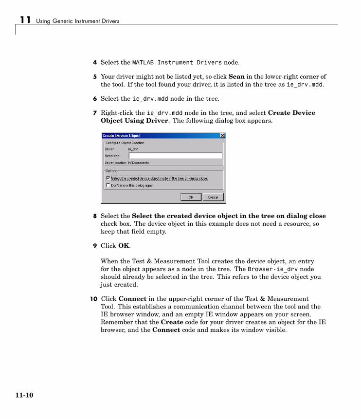
11 Using Generic Instrument Drivers
4 Select the MATLAB Instrument Drivers node.
5 Your driver might not be listed yet, so click Scan in the lower-right corner ofthe tool. If the tool found your driver, it is listed in the tree as ie_drv.mdd.
6 Select the ie_drv.mdd node in the tree.
7 Right-click the ie_drv.mdd node in the tree, and select Create DeviceObject Using Driver. The following dialog box appears.
8 Select the Select the created device object in the tree on dialog closecheck box. The device object in this example does not need a resource, sokeep that field empty.
9 Click OK.
When the Test & Measurement Tool creates the device object, an entryfor the object appears as a node in the tree. The Browser-ie_drv nodeshould already be selected in the tree. This refers to the device object youjust created.
10 Click Connect in the upper-right corner of the Test & MeasurementTool. This establishes a communication channel between the tool and theIE browser window, and an empty IE window appears on your screen.Remember that the Create code for your driver creates an object for the IEbrowser, and the Connect code and makes its window visible.
11-10

Example: Using a Generic Driver with the Test & Measurement Tool
Accessing PropertiesThe driver you created allows you to specify where the browser windowappears on your screen and how large it is.
1 Click the Properties tab, and then select Top in the Device objectproperties list.
The first value displayed for setting this property is 0.0.
2 Click Set. The IE browser window shifts upward to the top edge of yourscreen.
3 With the mouse, grab the IE window, and drag it down some distance fromthe top of the screen.
4 Now return to the Test & Measurement Tool window, and click Get forthe Top property. Notice in the Response pane how many pixels downyou have moved the window.
Use your driver Vsize property to change the size of the browser window.
1 Select Vsize in the Device object properties list.
2 Enter a property value of 200, and click Set. Notice the IE window size.
3 Enter a property value of 400 and click Set. Notice the IE window size.
4 Try resizing the IE browser window directly with the mouse. Then in theTest & Measurement Tool, click Get for the Vsize property. Notice thevalue returned to the Response pane.
Using FunctionsUse the goTo function of your generic driver to control the Web page thatthe browser displays.
1 In the Test & Measurement Tool, click the Functions tab for your deviceobject.
2 Select goTo in the list of Device object functions.
11-11

11 Using Generic Instrument Drivers
3 In the Input argument(s) field, enter 'www.mathworks.com'. Be sureto include the single quotes.
4 Click Execute. Observe the IE browser and see that it displays theMathWorks Web site.
5 Experiment freely. When you are finished, right-click the Browser-ie_drvnode in the tree and select Delete Object. Close the Test & MeasurementTool, and close the IE browser window you created in this example.
11-12

Example: Using a Generic Driver at the Command Line
Example: Using a Generic Driver at the Command Line
In this section...
“Creating and Connecting the Device Object” on page 11-13
“Accessing Properties” on page 11-14
“Using Functions” on page 11-15
Creating and Connecting the Device ObjectInstrument Control Toolbox provides MATLAB commands you can use in theCommand Window or in M-files to create a device object that uses a driver, setand get properties of the object, and execute functions.
This example illustrates how to use the generic driver you created in“Example: Writing a Generic Driver” on page 11-3.
1 If your driver is not in thematlabroot\toolbox\instrument\instrument\drivers directory, in theMATLAB Command Window, make sure that the directory containing yourdriver is on the MATLAB path.
path
If you do not see the directory in the path listing, and the driver is not inthe matlabroot\toolbox\instrument\instrument\drivers directory,add the directory to the path with the command
addpath directory
where directory is the pathname to the directory containing your driver.
2 Create a device object using your driver. For the driver used in thisexample, the icdevice function does not require an argument for aresource when using a generic driver. What the object connects to and howit makes that connection are defined in the Create code of your driver.
ie_obj = icdevice('ie_drv');
11-13

11 Using Generic Instrument Drivers
3 Connect the object.
connect(ie_obj);
When the device object is connected, an empty IE window appears onyour screen. Now you can communicate directly with the IE browser fromMATLAB.
Accessing PropertiesThe driver you created allows you to specify where the browser windowappears on your screen and how large it is. You read and write the propertiesof your device object with the get and set functions, respectively.
1 View all of the properties of your device object.
get(ie_obj)ConfirmationFcn =DriverName = ie_drv.mddDriverType = MATLAB genericInstrumentModel =Interface = [1x1 COM.internetexplorer_application]LogicalName =Name = Browser-ie_drvObjectVisibility = onRsrcName =Status = openTag =Timeout = 10Type = BrowserUserData = []
BROWSER specific properties:Top = 47Vsize = 593
11-14
Example: Using a Generic Driver at the Command Line
2 Most of the properties listed belong to all device objects. For thisexample, the properties of interest are those listed as BROWSER specificproperties, that is, Top and Vsize.
The Top property defines the IE browser window position in pixels from thetop of the screen. Vsize defines the vertical size of the window in pixels.
3 Shift the IE browser window to the top of the screen.
set(ie_obj, 'Top', 0);
4 With the mouse, grab and drag the IE browser window down away fromthe top of the screen.
5 Find the window’s new position by examining the Top property.
get(ie_obj, 'Top')ans =
120
Adjust the size of the window by setting the Vsize property.
set(ie_obj, 'Vsize', 200);
6 Make the window larger by increasing the property value.
set(ie_obj, 'Vsize', 600);
Using FunctionsBy using the goTo function of your generic driver, you can control the Webpage displayed in the IE browser window.
11-15

11 Using Generic Instrument Drivers
1 View all of the functions (methods) of your device object.
methods(ie_obj)
Methods for class icdevice:
Contents disp icdevice instrnotify methods size
class display igetfield instrument ne subsasgn
close end inspect invoke obj2mfile subsref
connect eq instrcallback isa open vertcat
ctranspose fieldnames instrfind isequal openvar
delete get instrfindall isetfield propinfo
devicereset geterror instrhelp isvalid selftest
disconnect horzcat instrhwinfo length set
Driver specific methods for class icdevice:
goTo
Most of the methods listed apply to all device objects. For this example,the method of interest is the one listed under Driver specific methods,that is, goTo.
2 Use the goTo function to specify the page for the IE browser to display.
invoke(ie_obj, 'goTo', 'www.mathworks.com');
If you have access to the Internet, the IE window should display theMathWorks Web site.
3 When you are finished with your example, clean up the MATLABworkspace by removing the object.
disconnect(ie_obj);delete(ie_obj);clear ie_obj;
4 Close the IE browser window you created in this example.
11-16

12
Saving and Loading theSession
This chapter describes how to save and load information associated with aninstrument control session. The sections are as follows.
Saving and Loading InstrumentObjects (p. 12-2)
Save instrument objects and theirassociated property values to disk asan M-file or as a MAT-file.
Debugging: Recording Informationto Disk (p. 12-6)
Save information to disk as a textfile. The saved information includesthe data transferred to and from theinstrument, and event information.
12 Saving and Loading the Session
Saving and Loading Instrument Objects
In this section...
“Saving Instrument Objects to an M-File” on page 12-2
“Saving Objects to a MAT-File” on page 12-4
Saving Instrument Objects to an M-FileYou can save an instrument object to an M-file using the obj2mfile function.obj2mfile provides you with these options:
• Save all property values or save only those property values that differ fromtheir default values.
Read-only property values are not saved. Therefore, read-only propertiesuse their default values when you load the instrument object into theMATLAB workspace. To determine if a property is read-only, use thepropinfo function or examine the property reference pages.
• Save property values using the set syntax or the dot notation.
If the UserData property is not empty, or if a callback property is set to acell array of values or a function handle, then the data stored in theseproperties is written to a MAT-file when the instrument object is saved.The MAT-file has the same name as the M-file containing the instrumentobject code.
For example, suppose you create the GPIB object g, return instrumentidentification information to the variable out, and store out in the UserDataproperty.
g = gpib('ni',0,1);g.Tag = 'My GPIB object';fopen(g)cmd = '*IDN?';fprintf(g,cmd)out = fscanf(g);g.UserData = out;
12-2

Saving and Loading Instrument Objects
The following command saves g and the modified property values to theM-file mygpib.m. Because the UserData property is not empty, its value isautomatically written to the MAT-file mygpib.mat.
obj2mfile(g,'mygpib.m');
Use the type command to display mygpib.m at the command line.
Loading the Instrument ObjectTo load an instrument object that was saved as an M-file into the MATLABworkspace, type the name of the M-file at the command line. For example,to load g from the M-file mygpib.m,
g = mygpib
The display summary for g is shown below. Note that the read-only propertiessuch as Status, BytesAvailable, ValuesReceived, and ValuesSent arerestored to their default values.
GPIB Object Using NI Adaptor : GPIB0-1
Communication AddressBoardIndex: 0PrimaryAddress: 1SecondaryAddress: 0
Communication StateStatus: closedRecordStatus: off
Read/Write StateTransferStatus: idleBytesAvailable: 0ValuesReceived: 0ValuesSent: 0
When loading g into the workspace, the MAT-file mygpib.mat is automaticallyloaded and the UserData property value is restored.
g.UserDataans =
12-3

12 Saving and Loading the Session
TEKTRONIX,TDS 210,0,CF:91.1CT FV:v1.16 TDS2CM:CMV:v1.04
Saving Objects to a MAT-FileYou can save an instrument object to a MAT-file just as you would anyworkspace variable — using the save command. For example, to save theGPIB object g and the variables cmd and out, defined in “Saving InstrumentObjects to an M-File” on page 12-2, to the MAT-file mygpib1.mat,
save mygpib1 g cmd out
Read-only property values are not saved. Therefore, read-only properties usetheir default values when you load the instrument object into the MATLABworkspace. To determine if a property is read-only, use the propinfo functionor examine the property reference pages.
Loading the Instrument ObjectTo load an instrument object that was saved to a MAT-file into the MATLABworkspace, use the load command. For example, to load g, cmd, and outfrom MAT-file mygpib1.mat,
load mygpib1
The display summary for g is shown below. Note that the read-only propertiessuch as Status, BytesAvailable, ValuesReceived, and ValuesSent arerestored to their default values.
GPIB Object Using NI Adaptor : GPIB0-1
Communication AddressBoardIndex: 0PrimaryAddress: 1SecondaryAddress: 0
Communication StateStatus: closedRecordStatus: off
12-4

Saving and Loading Instrument Objects
Read/Write StateTransferStatus: idleBytesAvailable: 0ValuesReceived: 0ValuesSent: 0
12-5

12 Saving and Loading the Session
Debugging: Recording Information to Disk
In this section...
“Using the record Function” on page 12-6
“Example: Introduction to Recording Information” on page 12-7
“Creating Multiple Record Files” on page 12-7
“Specifying a File Name” on page 12-8
“Record File Format” on page 12-8
“Example: Recording Information to Disk” on page 12-10
Using the record FunctionRecording information to disk provides a permanent record of your instrumentcontrol session, and is an easy way to debug your application. While theinstrument object is connected to the instrument, you can record thisinformation to a disk file:
• The number of values written to the instrument, the number of values readfrom the instrument, and the data type of the values
• Data written to the instrument, and data read from the instrument
• Event information
You record information to a disk file with the record function. The propertiesassociated with recording information to disk are given below.
Recording Properties
Property Name Description
RecordDetail Specify the amount of information saved to arecord file.
RecordMode Specify whether data and event information aresaved to one record file or to multiple record files.
12-6

Debugging: Recording Information to Disk
Recording Properties (Continued)
Property Name Description
RecordName Specify the name of the record file.
RecordStatus Indicate if data and event information are savedto a record file.
Example: Introduction to Recording InformationThis example creates the GPIB object g, records the number of valuestransferred between g and the instrument, and stores the information to thefile text myfile.txt.
g = gpib('ni',0,1);g.RecordName = 'myfile.txt';fopen(g)record(g)fprintf(g,'*IDN?')out = fscanf(g);
End the instrument control session.
fclose(g)delete(g)clear g
Use the type command to display myfile.txt at the command line.
Creating Multiple Record FilesWhen you initiate recording with the record function, the RecordModeproperty determines if a new record file is created or if new information isappended to an existing record file.
You can configure RecordMode to overwrite, append, or index. If RecordModeis overwrite, then the record file is overwritten each time recording isinitiated. If RecordMode is append, then the new information is appended tothe file specified by RecordName. If RecordMode is index, a different disk file
12-7

12 Saving and Loading the Session
is created each time recording is initiated. The rules for specifying a recordfile name are discussed in “Specifying a File Name” on page 12-8.
Specifying a File NameYou specify the name of the record file with the RecordName property. You canspecify any value for RecordName, including a directory path, provided thefile name is supported by your operating system. Additionally, if RecordModeis index, then the file name follows these rules:
• Indexed file names are identified by a number. This number precedes thefile name extension and is increased by 1 for successive record files.
• If no number is specified as part of the initial file name, then the firstrecord file does not have a number associated with it. For example, ifRecordName is myfile.txt, then myfile.txt is the name of the first recordfile, myfile01.txt is the name of the second record file, and so on.
• RecordName is updated after the record file is closed.
• If the specified file name already exists, then the existing file is overwritten.
Record File FormatThe record file is an ASCII file that contains a record of one or moreinstrument control sessions. You specify the amount of information saved to arecord file with the RecordDetail property.
RecordDetail can be compact or verbose. A compact record file contains thenumber of values written to the instrument, the number of values read fromthe instrument, the data type of the values, and event information. A verboserecord file contains the preceding information as well as the data transferredto and from the instrument.
Binary data with precision given by uchar, schar, (u)int8, (u)int16, or(u)int32 is recorded as hexadecimal values. For example, if the integer value255 is read from the instrument as a 16-bit integer, the hexadecimal value00FF is saved in the record file. Single- and double-precision floating-pointnumbers are recorded as decimal values using the %g format, and ashexadecimal values using the format specified by the IEEE Standard754-1985 for Binary Floating-Point Arithmetic.
12-8

Debugging: Recording Information to Disk
The IEEE floating-point format includes three components — the sign bit,the exponent field, and the significant field. Single-precision floating-pointvalues consist of 32 bits, and the value is given by
value = (-1)sign(2exp-127)(1.significand)
Double-precision floating-point values consist of 64 bits, and the value isgiven by
value = (-1)sign(2exp-1023)(1.significand)
The floating-point format component and the associated single-precision anddouble-precision bits are given below.
Format Component Single-Precision Bits Double-Precision Bits
sign 1 1
exp 2-9 2-12
significand 10-32 13-64
For example, suppose you record the decimal value 4.25 using thesingle-precision format. The record file stores 4.25 as the hex value 40880000,which is calculated from the IEEE single-precision floating-point format.To reconstruct the original value, convert the hex value to a decimal valueusing hex2dec:
dval = hex2dec('40880000')dval =
1.082654720000000e+009
Convert the decimal value to a binary value using dec2bin:
bval = dec2bin(dval,32)bval =01000000100010000000000000000000
The interpretation of bval is given by the preceding table. The leftmost bitindicates the value is positive because (-1)0 = 1. The next 8 bits correspondto the exponent, which is given by
exp = bval(2:9)
12-9

12 Saving and Loading the Session
exp =10000001
The decimal value of exp is 27+20 = 129. The remaining bits correspond to thesignificand, which is given by
significand = bval(10:32)significand =00010000000000000000000
The decimal value of significand is 2-4 = 0.0625. You reconstruct theoriginal value by plugging the decimal values of exp and significand intothe formula for IEEE singles:
value = (-1)0(2129 - 127)(1.0625)value = 4.25
Example: Recording Information to DiskThis example extends “Example: Reading Binary Data” on page 4-22 byrecording the associated information to a record file. Additionally, thestructure of the resulting record file is presented:
1 Create an instrument object — Create the GPIB object g associatedwith a National Instruments GPIB controller with board index 0, and aninstrument with primary address 1.
g = gpib('ni',0,1);
2 Configure properties — Configure the input buffer to accept a reasonablylarge number of bytes, and configure the timeout value to two minutesto account for slow data transfer.
g.InputBufferSize = 50000;g.Timeout = 120;
Configure g to execute the callback function instrcallback every time5000 bytes are stored in the input buffer.
g.BytesAvailableFcnMode = 'byte';g.BytesAvailableFcnCount = 5000;g.BytesAvailableFcn = @instrcallback;
12-10

Debugging: Recording Information to Disk
Configure g to record information to multiple disk files using the verboseformat. The first disk file is defined as WaveForm1.txt.
g.RecordMode = 'index';g.RecordDetail = 'verbose';g.RecordName = 'WaveForm1.txt';
3 Connect to the instrument — Connect g to the oscilloscope.
fopen(g)
4 Write and read data — Initiate recording.
record(g)
Configure the scope to transfer the screen display as a bitmap.
fprintf(g,'HARDCOPY:PORT GPIB')fprintf(g,'HARDCOPY:FORMAT BMP')fprintf(g,'HARDCOPY START')
Initiate the asynchronous read operation, and begin generating events.
readasync(g)
instrcallback is called every time 5000 bytes are stored in the inputbuffer. The resulting displays are shown below.
BytesAvailable event occurred at 09:04:33 for the object: GPIB0-1.BytesAvailable event occurred at 09:04:42 for the object: GPIB0-1.BytesAvailable event occurred at 09:04:51 for the object: GPIB0-1.BytesAvailable event occurred at 09:05:00 for the object: GPIB0-1.BytesAvailable event occurred at 09:05:10 for the object: GPIB0-1.BytesAvailable event occurred at 09:05:19 for the object: GPIB0-1.BytesAvailable event occurred at 09:05:28 for the object: GPIB0-1.
Wait until all the data is stored in the input buffer, and then transfer thedata to MATLAB as unsigned 8-bit integers.
out = fread(g,g.BytesAvailable,'uint8');
Toggle the recording state from on to off. Because the RecordMode value isindex, the record file name is automatically updated.
12-11
12 Saving and Loading the Session
record(g)g.RecordStatusans =offg.RecordNameans =WaveForm2.txt
5 Disconnect and clean up — When you no longer need g, you shoulddisconnect it from the instrument, and remove it from memory and fromthe MATLAB workspace.
fclose(g)delete(g)clear g
The Record File ContentsTo display the contents of the WaveForm1.txt record file,
type WaveForm1.txt
The record file contents are shown below. Note that data returned by thefread function is in hex format (most of the bitmap data is not shown).
Legend:* - An event occurred.> - A write operation occurred.< - A read operation occurred.
1 Recording on 18-Jun-2000 at 09:03:53.529. Binary data inlittle endian format.
2 > 18 ascii values.HARDCOPY:PORT GPIB
3 > 19 ascii values.HARDCOPY:FORMAT BMP
4 > 14 ascii values.HARDCOPY START
5 * BytesAvailable event occurred at 18-Jun-2000 at 09:04:33.3346 * BytesAvailable event occurred at 18-Jun-2000 at 09:04:41.7757 * BytesAvailable event occurred at 18-Jun-2000 at 09:04:50.805
12-12

Debugging: Recording Information to Disk
8 * BytesAvailable event occurred at 18-Jun-2000 at 09:04:00.2669 * BytesAvailable event occurred at 18-Jun-2000 at 09:05:10.30610 * BytesAvailable event occurred at 18-Jun-2000 at 09:05:18.77711 * BytesAvailable event occurred at 18-Jun-2000 at 09:05:27.77812 < 38462 uint8 values.
42 4d cf 03 00 00 00 00 00 00 3e 00 00 00 28 0000 00 80 02 00 00 e0 01 00 00 01 00 01 00 00 0000 00 00 96 00 00 00 00 00 00 00 00 00 00 00 00...ff ff ff ff ff ff ff ff ff ff ff ff ff ff ff ffff ff ff ff ff ff ff ff ff ff ff ff ff ff ff ffff ff ff ff ff ff ff ff ff ff ff ff ff ff
13 Recording off.
12-13

12 Saving and Loading the Session
12-14

13
Test & Measurement Tool
This chapter describes how to use the Test & Measurement Tool to accessyour hardware interfaces and instrument drivers.
Test & Measurement Tool: Overview(p. 13-2)
Describes the capabilities of theTest & Measurement Tool, itsappearance, and how to start it up.
Using the Test & Measurement Tool(p. 13-4)
Describes through examples how touse the Test & Measurement Tool tocommunicate with an instrument.
13 Test & Measurement Tool
Test & Measurement Tool: Overview
In this section...
“Instrument Control Toolbox Support” on page 13-2
“Navigating the Tree” on page 13-3
Instrument Control Toolbox SupportThe Test & Measurement Tool (tmtool) enables you to configure and controlresources (instruments, serial devices, drivers, interfaces, etc.) accessiblethrough the toolbox without having to write MATLAB script.
You can use the Test & Measurement Tool to manage your session with thetoolbox. This tool enables you to do the following:
• Detect available hardware and drivers.
• Connect to an instrument or device.
• Configure instrument or device settings.
• Read and write data.
• Automatically generate MATLAB script.
• Visualize acquired data.
• Export acquired data to the MATLAB environment.
13-2

Test & Measurement Tool: Overview
Navigating the TreeYou start the Test & Measurement Tool by typing
tmtool
You navigate to the various hardware control panes using the tool’s tree.Start by selecting the toolbox you want to work with, which displays a set ofinstructions in the right pane. These instructions explain the basic steps toestablishing communication with an instrument.
For example, the following figure shows the pane displayed when you selectInstrument Control Toolbox.
13-3

13 Test & Measurement Tool
Using the Test & Measurement Tool
In this section...
“Overview of the Examples” on page 13-4
“Hardware” on page 13-4
“Instrument Objects” on page 13-12
“Instrument Drivers” on page 13-16
Overview of the ExamplesThese examples illustrates a typical session using the Test & MeasurementTool for instrument control. The session entails communicating with aTektronix TDS 210 oscilloscope via a GPIB interface.
To start the tool, on the MATLAB command line, type:
tmtool
HardwareWhen the tool displays, expand (click the +) the Instrument ControlToolbox node in the tree. Next, expand the Hardware node. The tree nowlooks like this.
13-4

Using the Test & Measurement Tool
Selecting the Interface and Scanning for GPIB BoardsNext, scan for installed GPIB boards by selecting the GPIB node. The rightpane changes to the Installed GPIB Board list. Click Scan to see whatboards are installed. The following figure shows the scan result from a systemwith one Capital Equipment Corp and one Keithley GPIB board.
13-5

13 Test & Measurement Tool
Scanning for Instruments Connected to GPIB BoardsAfter determining what GPIB boards are installed, you must determine whatinstruments are connected to those boards. Expand the GPIB node and selecta board.
The right pane changes to the GPIB Instruments list. Click Scan to seewhat instruments are connected to this board. The following figure shows thescan result from a system with a Tektronix TDS 210 connected at primaryaddress 4.
13-6

Using the Test & Measurement Tool
Configuring the InterfaceYou can change the configuration of the interface by clicking the Configuretab. This pane displays properties you can set to configure the instrumentcommunication settings. In the following view of the Configure pane, theTimeout property value has been set to 15 seconds.
13-7

13 Test & Measurement Tool
Establishing the ConnectionExpand the keithley-Board-0 node and select the instrument at primaryaddress 4: PAD-4 (TEKTRONIX,TDS 210.... The right pane changes to thecontrol pane you use for writing and reading data to and from that instrument.
Click Connect to establish communication with the instrument. The toolcreates an interface object representing the communication channel to theinstrument.
13-8

Using the Test & Measurement Tool
Writing and Reading DataSelecting the Communicate tab displays the pane you use to write andread data. You can write and read data separately using the Write andRead buttons, or you can use the Query button to write and read in a singleoperation.
The following figure shows the pane after a brief session involving thefollowing steps:
1 Open communication with the instrument.
2 Enter *IDN? as Data to Write, and click Query (write/read). This executesthe identify command.
3 Enter CURVE? as Data to Write, and click Query. This retrieves thewaveform data from the scope.
13-9

13 Test & Measurement Tool
Exporting Instrument DataYou can export the data acquired from instruments to any of the following:
• MATLAB workspace as a variable
• Figure window as a plot
• MAT-file for storage in a file
• MATLAB array editor for modification
To export data, select File > Export > Instrument Response(s) from themenu bar. When the Data Exporter dialog box opens, choose the variables toexport. The following figure shows the Data Exporter set to export the curvedata to the MATLAB workspace as the variable data2.
Exporting the GPIB ObjectWhen you open a connection to an instrument, the Test & MeasurementTool creates an instrument object automatically. You can export the GPIBinstrument object created in this example as any of the following:
• MATLAB workspace object that you can use as an argument in instrumentcontrol commands
• M-file containing the call to the GPIB constructor and the commands toset object properties
• MAT-file for storage in a file
To export the object, select File > Export > Instrument Object from themenu bar. When the Object Exporter dialog box opens, choose the object to
13-10

Using the Test & Measurement Tool
export. The following figure shows the Object Exporter set to export the objectto an M-file. (When you run that M-file, it creates a new object with theequivalent settings.)
Saving Your Instrument Control Session. The Session Log tabdisplays the M-code equivalent of your instrument control session. You cansave this code to an M-file so that you can execute the same commandsprogrammatically.
Select File > Save Session Log from the menu bar or click Save Sessionon the Session Log pane. This opens the Export to M-File dialog box, whichenables you to specify a file name and directory location for the M-file.
13-11

13 Test & Measurement Tool
Instrument Objects
Interface ObjectsThe Test & Measurement Tool creates interface objects automaticallywhen you open a communication channel to an instrument by clicking theCommunication Status button. To explicitly create and configure aninterface object:
1 Expand the Instrument Objects node in the tree, and select InterfaceObjects. The Interface Objects pane appears on the right.
2 Click New Object to open the New Object Creation dialog box.
3 Specify the object parameters and click OK to create the new object.
Device ObjectsTo create and configure a device object:
1 Expand the Instrument Objects node in the tree, and select DeviceObjects. The Device Objects pane appears on the right.
2 Click New Object to open the New Object Creation dialog box. In thiscase, the Instrument object type is already set for device.
13-12

Using the Test & Measurement Tool
3 Specify or browse for the instrument driver you want to use; then choosefrom among the available interface objects, or create one if necessary.
4 Click OK to create the new device object.
Setting Instrument Object PropertiesWhether the instrument objects are created automatically, created throughthe New Object Creation dialog box, or created on the MATLAB commandline, the Test & Measurement Tool enables you to set the properties of theseobjects. To change object properties in the Test & Measurement Tool:
1 Expand the Instrument Objects node in the tree, then either InterfaceObjects or Device Objects, and select the object whose properties youwant to set.
2 Click the Configure tab in the right pane.
3 Set properties displayed in this pane, as shown in the following figures.
13-13

13 Test & Measurement Tool
Configuring Interface Object Properties
Configuring Device Object Properties
13-14

Using the Test & Measurement Tool
Communicating with Your Instrument
Using an Interface Object. When communicating with your instrumentusing an interface object, you send data to instrument in the form of rawinstrument commands. In the following figure, the Test & Measurement Toolsends the *RST string to the TDS 210 oscilloscope via an interface object. *RSTis the oscilloscope’s reset command.
Communicating via an Interface Object
13-15

13 Test & Measurement Tool
Using a Device Object. When communicating with your instrument using adevice object, instead of employing instrument commands, you invoke deviceobject methods (functions) or you set device object properties as provided bythe MATLAB instrument driver for that instrument.
In the following figure, the Test & Measurement Tool resets a TDS 210oscilloscope by issuing a call to the devicereset function of the instrumentdriver. Communicating this way, you don’t need to know what the actualoscilloscope reset command is.
Communicating via a Device Object
Instrument DriversThe Test & Measurement Tool enables you to scan for installed drivers, andto use those drivers when creating device objects.
13-16

Using the Test & Measurement Tool
MATLAB Instrument DriversMATLAB instrument drivers include
• MATLAB interface drivers
• MATLAB VXIplug&play drivers
• MATLAB IVI drivers
Select the MATLAB Instrument Drivers node in the tree. Then click Scanto get an updated display of all the installed MATLAB instrument driversfound on the MATLAB path.
13-17

13 Test & Measurement Tool
When the Test & Measurement Tool scans for drivers, it makes them availableas nodes under the driver type node. Expand the MATLAB InstrumentDrivers node to reveal the installed drivers. Select one of them to see thedriver’s details.
You can choose to see the driver’s properties or functions. When you select theparticular property or function, the tool displays that item’s description.
VXIplug&play DriversFor an example of scanning for installed XVIplug&play drivers with the Test& Measurement Tool, see “VXIplug&play Drivers” on page 9-4.
IVI DriversFor an example of scanning for installed IVI-C or IVI-COM drivers with theTest & Measurement Tool, see “IVI Drivers” on page 10-4. For using the Test& Measurement Tool to examine or configure an IVI configuration store, see“Configuring an IVI Configuration Store” on page 10-13.
13-18

14
Using the InstrumentDriver Editor
This chapter describes how to use the Instrument Driver Editor to create,import, or modify instrument drivers. The sections are as follows.
MATLAB Instrument Driver Editor:Overview (p. 14-2)
An explanation of MATLABinstrument drivers, their features,capabilities, and usage.
Creating MATLAB InstrumentDrivers (p. 14-5)
How to create, modify, save, andverify instrument drivers using theMATLAB Instrument Driver Editor.
Properties (p. 14-18) Defining instrument functionalityas properties of the device objectto ease communications with yourinstrument.
Functions (p. 14-34) Defining instrument functionalityas functions of the device objectto ease communications with yourinstrument.
Groups (p. 14-46) Combining common capabilities ofthe device object.
Using Existing Drivers (p. 14-65) Adapting existing drivers for yourinstrument.

14 Using the Instrument Driver Editor
MATLAB Instrument Driver Editor: Overview
In this section...
“What Is a MATLAB Instrument Driver?” on page 14-2
“How Does a MATLAB Instrument Driver Work?” on page 14-3
“Why Use a MATLAB Instrument Driver?” on page 14-3
What Is a MATLAB Instrument Driver?Instrument Control Toolbox provides the means of communicating directlywith a hardware instrument through an interface object. If you areprogramming directly through an interface object, you need to programwith the command language of the instrument itself. Any substitution ofinstrument, such as make or model, may require a change to the appropriateMATLAB code.
� ��������
��&'�$�
���������������
!���"������������
!���"�������������
���������-�� ��������
A MATLAB instrument driver offers a layer of interpretation between you andthe instrument. The instrument driver contains all the necessary commandsfor programming the instrument, so that you do not need to be aware of thespecific instrument commands. Instead, you can program the instrument withfamiliar or consistent device object properties and functions.
The following figure shows how a device object and instrument driver offera layer between the command line and the interface object. The instrumentdriver handles the instrument-level commands, so that as you program fromthe command line, you need only manipulate device object properties andfunctions, rather than instrument commands.
14-2

MATLAB Instrument Driver Editor: Overview
� ��������
��&'�$�
������������
��������������
������
���������������
!���"������������
!���"�������������
���������-�� ��������
������./��0�� ���������1��������
In addition to containing instrument commands, the instrument driver canalso contain MATLAB code to provide analysis based upon instrument setupor data.
Note For many instruments, a MATLAB instrument driver already existsand you will not need to create a MATLAB instrument driver for yourinstrument. For other instruments, there may be a similar MATLABinstrument driver and you will need to edit it. If you would like moreinformation on how to edit a MATLAB instrument driver, you may want tobegin with “Modifying MATLAB Instrument Drivers” on page 14-65.
How Does a MATLAB Instrument Driver Work?A MATLAB instrument driver contains information on the functionalitysupported by an instrument. You access this functionality through a deviceobject’s properties and functions.
When you query or configure a property of the device object using the getor set function, or when you call (invoke) a function on the device object,the MATLAB instrument driver provides a translation to determine whatinstrument commands are written to the instrument or what MATLAB codeis executed.
Why Use a MATLAB Instrument Driver?Using a MATLAB instrument driver isolates you from the instrumentcommands. Therefore, you do not need to be aware of the instrument syntax,but can use the same code for a variety of related instruments, ignoring thedifferences in syntax from one instrument to the next.
14-3

14 Using the Instrument Driver Editor
For example, suppose you have two different oscilloscopes in your shop, eachwith its own set of commands. If you want to perform the same tasks withthe two different instruments, you can create an instrument driver for eachscope so that you can control each with the same code. Then substitution ofone instrument for another does not require a change in the MATLAB codebeing used to control it, but only a substitution of the instrument driver.
14-4

Creating MATLAB Instrument Drivers
Creating MATLAB Instrument Drivers
In this section...
“Driver Components” on page 14-5
“MATLAB Instrument Driver Editor Features” on page 14-6
“Saving MATLAB Instrument Drivers” on page 14-6
“Driver Summary and Control Commands” on page 14-6
“Initialization and Cleanup” on page 14-10
Driver ComponentsA MATLAB instrument driver contains information about an instrument anddefines the functionality supported by the instrument.
Driver Component Description
Driver Summary andControl Commands
Basic information about the instrument, e.g.,manufacturer or model number.
Initialization andCleanup
Code that is executed at various stages in theinstrument control session, e.g., code that isexecuted upon connecting to the instrument.
Properties A property is generally used to configure or queryan instrument’s state information.
Functions A function is generally used to control or configurean instrument.
Groups A group combines common functionality of theinstrument into one component.
Depending on the instrument and the application for which the driver is beingused, all components of the driver may not be defined. You can define thenecessary driver components needed for your application with the MATLABInstrument Driver Editor.
14-5
14 Using the Instrument Driver Editor
MATLAB Instrument Driver Editor FeaturesThe MATLAB Instrument Driver Editor is a tool that creates or edits aMATLAB instrument driver. Specifically, it allows you to do the following:
• Add/remove/modify properties.
• Add/remove/modify functions .
• Define MATLAB code to wrap around commands sent to instrument.
You can open the MATLAB Instrument Driver Editor with the mideditcommand.
In the rest of this section, each driver component will be described andexamples will be shown on how to add the driver component informationto a new MATLAB instrument driver called tektronix_tds210_ex.mdd.The tektronix_tds210_ex.mdd driver will define basic information andinstrument functionality for a Tektronix TDS 210 oscilloscope.
Saving MATLAB Instrument DriversYou can save an instrument driver to any directory with anyname. It is recommended that the instrument driver be saved to adirectory in the MATLAB path and that the name follows the formatmanufacturer_model.mdd. For example, an instrument that is usedwith a Tektronix TDS 210 oscilloscope should be saved with the nametektronix_tds210.mdd.
Driver Summary and Control CommandsYou can assign basic information about the instrument to the MATLABinstrument driver. Summary information can be used to identify the MATLABinstrument driver and the instrument that it represents. Control commandscan be used to reset, test, and read error messages from the instrument.Together, this information can be used to initialize and verify the instrument.
Topics in this section include
• “Driver Summary” on page 14-7
• “Control Commands” on page 14-7
14-6

Creating MATLAB Instrument Drivers
• “Example: Defining Driver Summary and Control Commands” on page 14-7
• “Verifying Driver Summary and Control Commands” on page 14-9
Driver SummaryYou can assign basic information that describes your instrument in theinstrument driver. This information includes the manufacturer of theinstrument, the model number of the instrument and the type of theinstrument. A version can also be assigned to the driver to assist in revisioncontrol.
Control CommandsYou can define basic control commands supported by the instrument. Thecontrol commands can be accessed through device object properties andfunctions.
ControlCommand
Accessed withDevice Object’s
Example InstrumentCommand
Description
Identify InstrumentModelproperty
*IDN? Returns the identificationstring of the instrument
Reset deviceresetfunction
*RST Returns the instrument to aknown state
Self test selftest function *TST? Tests the instrument’sinterface
Error geterror function ErrLog:Next? Retrieves the nextinstrument error message
The MATLAB Instrument Driver Editor assigns default values for the controlcommands. The control commands should be modified appropriately to matchthe instrument’s command set.
Example: Defining Driver Summary and Control CommandsThis example defines the basic driver information and control commands for aTektronix TDS 210 oscilloscope using the MATLAB Instrument Driver Edito.,
1 Select the Summary node in the tree.
14-7

14 Using the Instrument Driver Editor
2 In the Driver summary pane:
a Enter Tektronix in the Manufacturer field.
b Enter TDS 210 in the Model field.
c Select Oscilloscope in the Instrument type field.
d Enter 1.0 in the Driver version field.
3 In the Control commands pane:
a Leave the Identify field with *IDN?.
b Leave the Reset field with *RST.
c Leave the Self test field with *TST?
d Update the Error field with ErrLog:Next?
4 Click the Save button. Specify the name of the instrument driver astektronix_tds210_ex.mdd.
14-8

Creating MATLAB Instrument Drivers
Note For additional information on instrument driver nomenclature, refer to“Saving MATLAB Instrument Drivers” on page 14-6.
Verifying Driver Summary and Control CommandsThis procedure verifies the summary information defined in the DriverSummary and Control Commands panes. In this example, the driver nameis tektronix_tds210_ex.mdd. Communication with the Tektronix TDS 210oscilloscope at primary address 2 is done via a Keithley GPIB board at boardindex 0. From the MATLAB command line,
1 Create the device object, obj, using the icdevice function.
g = gpib('keithley', 0, 2);obj = icdevice('tektronix_tds210_ex.mdd', g);
2 View the defined driver information.
obj
Instrument Device Object Using Driver : tektronix_tds210_ex.mdd
Instrument InformationType OscilloscopeManufacturer TektronixModel TDS 210
Driver InformationDriverType MATLAB Instrument DriverDriverName tekronix_tds210_ex.mddDriverVersion 1.0
Communication StateStatus closed
instrhwinfo(obj)ans =
Manufacturer: 'Tektronix'Model: 'TDS 210'
14-9

14 Using the Instrument Driver Editor
Type: 'Oscilloscope'DriverName: 'h:\documents\tektronix_tds210_ex.mdd'
3 Connect to the instrument.
connect(obj)
4 Verify the control commands.
get(obj, 'InstrumentModel')ans =
TEKTRONIX,TDS 210,0,CF:91.1CT FV:v2.03 TDS2MM:MMV:v1.04
devicereset(obj)selftest(obj)ans =
0
geterror(obj)ans =
''
5 Disconnect from the instrument and delete the objects.
disconnect(obj)delete([obj g])
Initialization and CleanupThis section describes how to define code that is executed at different stages inthe instrument control session, so that the instrument can be set to a desiredstate at particular times. Specifically, you can define code that is executedafter the device object is created, after the device object is connected to theinstrument, or before the device object is disconnected from the instrument.Depending on the stage, the code can be defined as a list of instrumentcommands that will be written to the instrument or as MATLAB code.
Topics in this section include
• Definitions of the types of code that can be defined
• Examples of code for each supported stage
14-10

Creating MATLAB Instrument Drivers
• Steps used to verify the code
Create CodeYou define create code to ensure that the device object is configured to supportthe necessary properties and functions:
• Create code is evaluated immediately after the device object is created.
• Create code can only be defined as MATLAB code.
Example: Defining Create CodeThis examples defines the create code that ensures that the device object cantransfer the maximum waveform size, 2500 data points, supported by theTektronix TDS 210 oscilloscope. In the MATLAB instrument driver editor,
1 Select the Initialization and Cleanup node in the tree.
2 Click the Create tab and enter the MATLAB code to execute on deviceobject creation.
% Get the interface object and disconnect from instrument.g = get(obj, 'Interface');fclose(g);
% Configure the interface object's buffers to handle up to% 2500 points (two bytes per point requires 5000 bytes).set(g, 'InputBufferSize', 5000);set(g, 'OutputBufferSize', 5000);
3 Click the Save button.
14-11

14 Using the Instrument Driver Editor
Verifying Create CodeThis procedure verifies the MATLAB create code defined. In this example,the driver name is tektronix_tds210_ex.mdd. Communication with theTektronix TDS 210 oscilloscope at primary address 2 is done via a KeithleyGPIB board at board index 0.
1 From the MATLAB command line, create the interface object, g; and verifythe default input and output buffer size values.
g = gpib('keithley', 0, 2);get(g, {'InputBufferSize', 'OutputBufferSize'})ans =
[512] [512]
2 Create the device object, obj, using the icdevice function.
obj = icdevice('tektronix_tds210_ex.mdd', g);
3 Verify the create code by querying the interface object’s buffer sizes.
get(g, {'InputBufferSize', 'OutputBufferSize'})ans =
[5000] [5000]
14-12

Creating MATLAB Instrument Drivers
4 Delete the objects.
delete([obj g])
Connect CodeIn most cases you need to know the state or configuration of the instrumentwhen you connect the device object to it. You can define connect code to ensurethat the instrument is properly configured to support the device object’sproperties and functions.
Connect code is evaluated immediately after the device object is connected tothe instrument with the connect function. The connect code can be definedas a series of instrument commands that will be written to the instrumentor as MATLAB code.
Example: Defining Connect CodeThis examples defines the connect code that ensures the Tektronix TDS 210oscilloscope is configured to support the device object properties and functions.Specifically, the instrument will be returned to a known set of instrumentsettings (instrument reset) and the instrument will be configured to omitheaders on query responses.
1 From the MATLAB instrument driver editor, select the Initializationand Cleanup node in the tree.
2 Click the Connect tab and enter the instrument commands to executewhen the device object is connected to the instrument.
• Select Instrument Commands from the Function style menu.
• Enter the *RST command in the Command text field, and then clickAdd.
• Enter the HEADER OFF command in the Command text field, and thenclick Add.
3 Click the Save button.
14-13

14 Using the Instrument Driver Editor
Verifying Connect CodeThis procedure verifies the instrument commands defined in the connectcode. In this example, the driver name is tektronix_tds210_ex.mdd.Communication with the Tektronix TDS 210 oscilloscope at primary address 2is done via a Keithley GPIB board at board index 0.
1 From the MATLAB command line, create the device object, obj, usingthe icdevice function.
g = gpib('keithley', 0, 2);obj = icdevice('tektronix_tds210_ex.mdd', g);
2 Connect to the instrument.
connect(obj)
3 Verify the connect code by querying the Header state of the instrument.
query(g, 'Header?')ans =
0
14-14

Creating MATLAB Instrument Drivers
4 Disconnect from the instrument and delete the objects.
disconnect(obj)delete([obj g])
Disconnect CodeBy defining disconnect code, you can ensure that the instrument and thedevice object are returned to a known state after communication with theinstrument is completed.
Disconnect code is evaluated before the device object’s being disconnected fromthe instrument with the disconnect function. This allows the disconnectcode to communicate with the instrument. Disconnect code can be defined asa series of instrument commands that will be written to the instrument orit can be defined as MATLAB code.
Example: Defining Disconnect CodeThis example defines the disconnect code that ensures that the Tektronix TDS210 oscilloscope is returned to a known state after communicating with theinstrument using the device object.
1 From the MATLAB instrument driver editor, select the Initializationand Cleanup node in the tree.
2 Click the Disconnect tab and enter the MATLAB code to execute whenthe device object is disconnected from the instrument.
• Select M-Code from the Function style menu.
• Define the MATLAB code that will reset the instrument and configurethe interface object’s buffers to their default values.
% Get the interface object.g = get(obj, 'Interface');
% Reset the instrument to a known state.fprintf(g, '*RST');
3 Click the Save button.
14-15

14 Using the Instrument Driver Editor
Verifying Disconnect CodeThis procedure verifies the MATLAB code defined in the disconnect code. Inthis example, the driver name is tektronix_tds210_ex.mdd. Communicationwith the Tektronix TDS 210 oscilloscope at primary address 2 is done via aKeithley GPIB board at board index 0. From the MATLAB command line,
1 Create the device object, obj, using the icdevice function.
g = gpib('keithley', 0, 2);obj = icdevice('tektronix_tds210_ex.mdd', g);
2 Connect to the instrument.
connect(obj)
3 Alter some setting on the instrument so that a change can be observedwhen you disconnect. For example, the oscilloscope’s contrast can bechanged by pressing its front pane Display button, and then the ContrastDecrease button.
4 Disconnect from the instrument and observe that its display resets.
disconnect(obj)
14-16

Creating MATLAB Instrument Drivers
5 Delete the objects.
delete([obj g])
14-17

14 Using the Instrument Driver Editor
Properties
In this section...
“Properties: Overview” on page 14-18
“Property Components” on page 14-18
“Examples of Properties” on page 14-21
Properties: OverviewYou can make the programming of instruments through device objects easierand more consistent by using properties. A property can be used to query orset an instrument setting or attribute. For example, an oscilloscope’s triggerlevel may be controlled with a property called TriggerLevel, which you canread or control with the get or set function. Even if two different scopes havedifferent trigger syntax, you can use the same property name, TriggerLevel,to control them, because each scope will have its own instrument driver.
Another advantage of properties is that you can define them with certainacceptable values (enumerated) or limits (bounded) that can be checked beforethe associated commands are sent to the instrument.
Property ComponentsThe behavior of the property is defined by the following components.
Set CodeThe set code defines the code that is executed when the property is configuredwith the set function. The set code can be defined as an instrument commandthat will be written to the instrument or it can be defined as MATLAB code.
If the set code is M-code, it can include any number of commands or MATLABcode wrapped around instrument commands to provide additional processingor analysis.
If the set code is defined as an instrument command, then the commandwritten to the instrument will be the instrument command concatenatedwith a space and the value specified in the call to set. For example, the
14-18

Properties
set code for the DisplayContrast property is defined as the instrumentcommand DISplay:CONTRast. When the set function below is evaluated, theinstrument command sent to the instrument will be DISplay:CONTRast 54.
set(obj, 'DisplayContrast', 54);
Get CodeThe get code defines the code that is executed when the property value isqueried with the get function. The get code can be defined as an instrumentcommand that will be written to the instrument or it can be defined asMATLAB code.
Note The M-code used for your property’s get code and set code cannotinclude calls to the fclose or fopen functions on the interface object beingused to access your instrument.
Accepted Property ValuesYou can define the values that the property can be set to so that only validvalues are written to the instrument and an error would be returned beforean invalid value could be written to the instrument.
• A property value can be defined as a double, a string, or a Boolean.
• A property value that is defined as a double can be restricted to accept onlydoubles within a certain range or a list of enumerated doubles. For example,a property could be defined to accept a double within the range of [0 10] ora property could be defined to accept one of the values [1,7,8,10].
• A property value that is defined as a string can be restricted to accepta list of enumerated strings. For example, a property could be definedto accept the strings min and max.
Additionally, a property can be defined to accept multiple property valuedefinitions. For example, a property could be defined to accept a doubleranging between [0 10] or the strings min and max.
14-19

14 Using the Instrument Driver Editor
Property Value DependenciesA property value can be dependent upon another property’s value. Forexample, in controlling a power supply, the property VoltageLevel can beconfigured to the following values:
• A double ranging between 0 and 10 when the value of propertyVoltageOutputRange is high
• A double ranging between 0 and 5 when the value of propertyVoltageOutputRange is low
When VoltageLevel is configured, the value of VoltageOutputRange isqueried. If the value of VoltageOutputRange is high, then VoltageLevelcan be configured to a double ranging between 0 and 10. If the value ofVoltageOutputRange is low, then VoltageLevel can be configured to a doubleranging between 0 and 5.
Default ValueThe default value of the property is the value that the property is configuredto when the object is created.
Read-Only ValueThe read-only value of the property defines when the property can beconfigured. Valid options are described below.
Read-OnlyValue
Description
Never The property can be configured at all times with theset function.
While Open The property can only be configured with the setfunction when the device object is not connected to theinstrument. A device object is disconnected from theinstrument with the disconnect function.
Always The property cannot be configured with the setfunction.
14-20
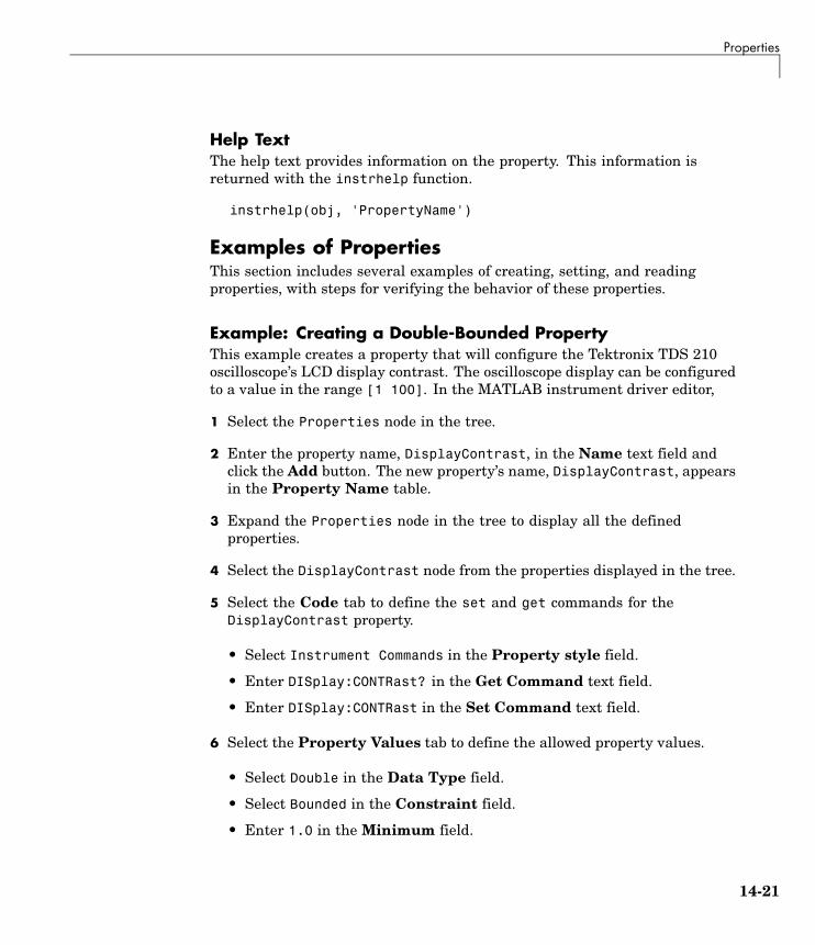
Properties
Help TextThe help text provides information on the property. This information isreturned with the instrhelp function.
instrhelp(obj, 'PropertyName')
Examples of PropertiesThis section includes several examples of creating, setting, and readingproperties, with steps for verifying the behavior of these properties.
Example: Creating a Double-Bounded PropertyThis example creates a property that will configure the Tektronix TDS 210oscilloscope’s LCD display contrast. The oscilloscope display can be configuredto a value in the range [1 100]. In the MATLAB instrument driver editor,
1 Select the Properties node in the tree.
2 Enter the property name, DisplayContrast, in the Name text field andclick the Add button. The new property’s name, DisplayContrast, appearsin the Property Name table.
3 Expand the Properties node in the tree to display all the definedproperties.
4 Select the DisplayContrast node from the properties displayed in the tree.
5 Select the Code tab to define the set and get commands for theDisplayContrast property.
• Select Instrument Commands in the Property style field.
• Enter DISplay:CONTRast? in the Get Command text field.
• Enter DISplay:CONTRast in the Set Command text field.
6 Select the Property Values tab to define the allowed property values.
• Select Double in the Data Type field.
• Select Bounded in the Constraint field.
• Enter 1.0 in the Minimum field.
14-21

14 Using the Instrument Driver Editor
• Enter 100.0 in the Maximum field.
7 Select the General tab to finish defining the property behavior.
• Enter 50 in the Default value text field.
• Select never in the Read only field.
• In the Help text field, enter Sets or queries the contrast of theLCD display.
8 Click the Save button.
14-22

Properties
Verifying the Behavior of the Property. This procedure verifiesthe behavior of the property. In this example, the driver name istektronix_tds210_ex.mdd. Communication with the Tektronix TDS 210oscilloscope at primary address 2 is done via a Keithley GPIB board at boardindex 0. From the MATLAB command line,
1 Create the device object, obj, using the icdevice function.
g = gpib('keithley', 0, 2);obj = icdevice('tektronix_tds210_ex.mdd', g);
2 View the DisplayContrast property’s current value. Calling get on theobject lists all its properties.
get(obj)
Calling get on the DisplayContrast property lists its current value.
get(obj, 'DisplayContrast ')ans =
50
14-23

14 Using the Instrument Driver Editor
3 View acceptable values for the DisplayContrast property. Calling set onthe object lists all its settable properties.
set(obj)
Calling set on the DisplayContrast property lists the values to which youcan set the property.
set(obj, 'DisplayContrast')[ 1.0 to 100.0 ]
4 Try setting the property to values inside and outside of the specified range.
set(obj, 'DisplayContrast', 17)get(obj, 'DisplayContrast')ans =
17set(obj, 'DisplayContrast', 120)??? Invalid value for DisplayContrast. Valid values: a valuebetween 1.0 and 100.0.
5 View the help you wrote.
instrhelp(obj,'DisplayContrast')DISPLAYCONTRAST [ 1.0 to 100.0 ]Sets or queries the contrast of the LCD display.
6 List the DisplayContrast characteristics that you defined in the PropertyValues and General tabs.
info = propinfo(obj,'DisplayContrast')info =
Type: 'double'Constraint: 'bounded'
ConstraintValue: [1 100]DefaultValue: 50
ReadOnly: 'never'InterfaceSpecific: 1
7 Connect to your instrument to verify the set and get code.
connect(obj)
14-24

Properties
When you issue the get function in MATLAB, thetektronix_tds210_ex.mdd driver actually sends the DISplay:CONTRast?command to the instrument.
get(obj, 'DisplayContrast')ans =
17
When you issue the set function in MATLAB, thetektronix_tds210_ex.mdd driver actually sends the DISplay:CONTRast34 command to the instrument.
set(obj, 'DisplayContrast', 34)
8 Finally, disconnect from the instrument and delete the objects.
disconnect(obj)delete([obj g])
Example: Creating an Enumerated PropertyThis example creates a property that will select and display the TektronixTDS 210 oscilloscope’s cursor. The oscilloscope allows two types of cursor.It supports a horizontal cursor that measures the vertical units in volts,divisions, or decibels, and a vertical cursor that measures the horizontal unitsin time or frequency. In the MATLAB instrument driver editor,
1 Select the Properties node in the tree.
2 Enter the property name, CursorType, in the Name text field and clickthe Add button. The new property’s name CursorType appears in theProperty Name table.
3 Expand the Properties node to display all the defined properties.
4 Select the CursorType node from the properties displayed in the tree.
5 Select the Code tab to define the set and get commands for theCursorType property.
• Select Instrument Commands in the Property style field.
• Enter CURSor:FUNCtion? in the Get Command text field.
14-25

14 Using the Instrument Driver Editor
• Enter CURSor:FUNCtion in the Set Command text field.
6 Select the Property Values tab to define the allowed property values.
• Select String in the Data Type field.
• Select Enumeration in the Constraint field.
• Enter none in the New property value text field and click the Addbutton. Then enter OFF in the Instrument Value table field.
• Similarly add the property value voltage, with instrument value HBArs.
• Similarly add the property value time, with instrument value VBArs.
7 Select the General tab to finish defining the property behavior.
• Enter none in the Default value text field.
• Select never in the Read only field.
• In the Help text field, enter Specifies the type of cursor.
14-26

Properties
8 Click the Save button.
Verifying the Behavior of the Property. This procedure verifiesthe behavior of the property. In this example, the driver name istektronix_tds210_ex.mdd. Communication with the Tektronix TDS 210oscilloscope at primary address 2 is done via a Keithley GPIB board at boardindex 0. From the MATLAB command line,
1 Create the device object, obj, using the icdevice function.
g = gpib('keithley', 0, 2);obj = icdevice('tektronix_tds210_ex.mdd', g);
2 View the CursorType property’s current value. Calling get on the objectlists all its properties.
get(obj)
Calling get on the CursorType property lists its current value.
get(obj, 'CursorType')ans =
none
3 View acceptable values for the CursorType property. Calling set on theobject lists all its settable properties.
set(obj)
Calling set on the CursorType property lists the values to which you canset the property.
set(obj, 'CursorType')[ {none} | voltage | time ]
4 Try setting the property to valid and invalid values.
set(obj, 'CursorType', 'voltage')get(obj, 'CursorType')ans =
voltageset(obj, 'CursorType', 'horizontal')
14-27

14 Using the Instrument Driver Editor
??? The 'horizontal' enumerated value is invalid.
5 View the help you wrote.
instrhelp(obj,'CursorType')CURSORTYPE [ {none} | voltage | time ]Specifies the type of cursor.
6 List the CursorType characteristics that you defined in the PropertyValues and General tabs.
info = propinfo(obj,'CursorType')info =
Type: 'string'Constraint: 'enum'
ConstraintValue: {3x1 cell}DefaultValue: 'none'
ReadOnly: 'never'InterfaceSpecific: 1
info.ContraintValueans ='none''voltage''time'
7 Connect to your instrument to verify the set and get code.
connect(obj)
When you issue the set function in MATLAB, thetektronix_tds210_ex.mdd driver actually sends the CURSor:FUNCtionVBArs command to the instrument.
set(obj, 'CursorType', 'time')
When you issue the get function in MATLAB, thetektronix_tds210_ex.mdd driver actually sends the CURSor:FUNCtion?command to the instrument.
get(obj,'CursorType')ans =
14-28

Properties
time
8 Finally disconnect from the instrument and delete the objects.
disconnect(obj)delete([obj g])
Example: An M-Code Style PropertyThis example creates a property that will return the difference between twocursors of the Tektronix TDS 210 oscilloscope. The oscilloscope allows twotypes of cursor. It supports a horizontal cursor that measures the verticalunits in volts, divisions, or decibels, and a vertical cursor that measuresthe horizontal units in time or frequency. The previous example created aproperty, CursorType, that selects and displays the oscilloscope’s cursor. Inthe MATLAB instrument driver editor,
1 Select the Properties node in the tree.
2 Enter the property name, CursorDelta, in the New Property text fieldand click Add. The new property’s name, CursorDelta, appears in theProperty Name table.
3 Expand the Properties node to display all the defined properties.
4 Select the CursorDelta node from the properties displayed in the tree.
5 Select the Code tab to define the set and get commands for theCursorDelta property.
• Select M-Code in the Property style field.
• Since the CursorDelta property is read-only, no MATLAB code will beadded to the MATLAB Set Function text field.
• The following MATLAB code is added to the MATLAB Get Functiontext field.
% Extract the interface object.interface = get(obj, 'Interface');
% Determine the type of cursor being displayed.type = get(obj, 'CursorType')
14-29

14 Using the Instrument Driver Editor
% Based on the cursor type, query the instrument.switch (type)case 'none'
propertyValue = 0;case 'voltage'
propertyValue = query(interface, 'CURSor:HBArs:DELTa?');propertyValue = str2double(propertyValue);
case 'time'propertyValue = query(interface, 'CURSor:VBArs:DELTa?');propertyValue = str2double(propertyValue);
end
6 Select the Property Values tab to define the allowed property values.
14-30

Properties
• Select Double in the Data Type field.
• Select None in the Constraint field.
7 Select the General tab to finish defining the property behavior.
• Enter 0 in the Default value text field.
• Select always in the Read only field.
• In the Help text field, enter Returns the difference between thetwo cursors.
8 Click the Save button.
Verifying the Behavior of the Property. This procedure verifiesthe behavior of the property. In this example, the driver name istektronix_tds210_ex.mdd. Communication with the Tektronix TDS 210oscilloscope at primary address 2 is done via a Keithley GPIB board at boardindex 0. From the MATLAB command line,
1 Create the device object, obj, using the icdevice function.
g = gpib('keithley', 0, 2);obj = icdevice('tektronix_tds210_ex.mdd', g);
2 View the CursorDelta property’s current value. Calling get on the objectlists all its properties.
get(obj)
3 Calling get on the CursorDelta property lists its current value.
get(obj, 'CursorDelta')ans =
0
4 Calling set on the object lists all its settable properties. Note that as aread-only property, CursorDelta is not listed in the output.
set(obj)
5 Calling set on the CursorDelta property results in an error message.
14-31

14 Using the Instrument Driver Editor
set(obj, 'CursorDelta')??? Attempt to modify read-only device property: 'CursorDelta'.
6 Setting the property to a value results in an error message.
set(obj, 'CursorDelta', 4)??? Changing the 'CursorDelta' property of device objects is notallowed.
7 View the help you wrote.
instrhelp(obj,'CursorDelta')CURSORDELTA (double) (read only)Returns the difference between the two cursors.
8 List the CursorDelta characteristics that you defined in the PropertyValues and General tabs.
info = propinfo(obj,'CursorDelta')info =
Type: 'double'Constraint: 'none'
ConstraintValue: []DefaultValue: 0
ReadOnly: 'always'InterfaceSpecific: 1
9 Connect to your instrument to verify the get code.
connect(obj)
When you issue the get function in MATLAB, thetektronix_tds210_ex.mdd driver actually executes the MATLAB codethat was specified.
get(obj, 'CursorDelta')ans =
1.6000
14-32

Properties
10 Finally, disconnect from the instrument and delete the objects.
disconnect(obj)delete([obj g])
14-33

14 Using the Instrument Driver Editor
Functions
In this section...
“Understanding Functions” on page 14-34
“Function Components” on page 14-34
“Examples of Functions” on page 14-35
Understanding FunctionsFunctions allow you to call the instrument to perform some task or tasks,which may return results as text data or numeric data. The function mayinvolve a single command to the instrument, or a sequence of instrumentcommands. A function may include MATLAB code to determine whatcommands are sent to the instrument or to perform analysis on data returnedfrom the instrument. For example, a function may request that a meter runits self-calibration, returning the status as a result. Another function mayread a meter’s scaling, request a measurement, adjust the measured dataaccording to the scale reading, and then return the result.
Function ComponentsThe behavior of the function is defined by the components described below.
CodeThe code defines the code that is executed when the function is evaluated withthe invoke function. The code can be defined as an instrument command thatwill be written to the instrument or it can be defined as MATLAB code.
If the code is defined as an instrument command, the instrument commandcan be defined to take an input argument. All occurrences of <inputargument name> in the instrument command are substituted with the inputvalue passed to the invoke function. For example, if a function is definedwith an input argument, start, and the instrument command is defined asData:Start <start>, and a start value of 10 is passed to the invoke function,the command Data:Start 10 is written to the instrument.
14-34

Functions
If the code is defined as an instrument command, the instrument commandcan also be defined to return an output argument. The output argument canbe returned as numeric data or as text data.
If the code is defined as MATLAB code, you can determine which commandsare sent to the instrument, and the data results from the instrument can bemanipulated, adjusted, or analyzed as needed.
Note The M-code used for your function’s MATLAB code cannot include callsto the fclose or fopen functions on the interface object being used to accessyour instrument.
Help TextThe help text provides information on the function.
Examples of FunctionsThis section includes several examples of functions, and steps to verify thebehavior of these functions.
Example: A Simple FunctionThis example creates a function that will cause the Tektronix TDS 210oscilloscope to adjust its vertical, horizontal and trigger controls to display astable waveform. In the MATLAB instrument driver editor,
1 Select the Functions node in the tree.
2 Enter the function name, autoset, in the Add function text field andclick the Add button. The new function’s name, autoset, appears in theFunction Name table.
3 Expand the Functions node to display all the defined functions.
4 Select the autoset node from the functions displayed in the tree.
5 Select the Code tab to define commands executed for this function.
14-35

14 Using the Instrument Driver Editor
• Select Instrument Commands in the Function style field.
• In the Define function commands pane, enter AUTOSet EXECute inthe Add command field and click the Add button.
6 Select the Help tab to define the help text for this function.
• In the Help text field, enter INVOKE(OBJ, 'autoset') causes theoscilloscope to adjust its vertical, horizontal, and triggercontrols to display a stable waveform.
7 Click the Save button.
Verifying the Behavior of the Function. This procedure verifiesthe behavior of the function. In this example, the driver name istektronix_tds210_ex.mdd. Communication with the Tektronix TDS 210oscilloscope at primary address 2 is done via a Keithley GPIB board at boardindex 0. From the MATLAB command line,
1 Create the device object, obj, using the icdevice function.
g = gpib('keithley', 0, 2);obj = icdevice('tektronix_tds210_ex.mdd', g);
14-36

Functions
2 View the method you created.
methods(obj)
Methods for class icdevice:
Contents error instrhwinfo openclass fieldnames instrnotify openvarclose get instrument propinfoconnect geterror invoke selftestctranspose horzcat isa setdelete icdevice isequal simdevicereset igetfield isetfield sizedisconnect inspect isvalid subsasgndisp instrcallback length subsrefdisplay instrfind methods vertcatend instrfindall neeq instrhelp obj2mfile
Driver specific methods for class icdevice:
autoset
3 View the help you wrote.
instrhelp(obj, 'autoset')INVOKE(OBJ, 'autoset') causes the oscilloscope to adjust itsvertical, horizontal, and trigger controls to display a stablewaveform.
4 Using the controls on the instrument, set the scope so that its display isunstable. For example, set the trigger level outside the waveform rangeso that the waveform scrolls across the display.
5 Connect to your instrument and execute the function. Observe how thedisplay of the waveform stabilizes.
connect(obj)invoke(obj, 'autoset')
14-37

14 Using the Instrument Driver Editor
6 Disconnect from your instrument and delete the object.
disconnect(obj)delete([obj g])
Example: A Function with Instrument Commands that UseInput and Output ArgumentsThis example creates a function that configures which waveform will betransferred from the Tektronix TDS 210 oscilloscope, and configures thewaveform’s starting and ending data points. In the MATLAB instrumentdriver editor,
1 Select the Functions node in the tree.
2 Enter the function name, configureWaveform, in the New functiontext field and click the Add button. The new function’s name,configureWaveform, appears in the Function Name table.
3 Expand the Functions node to display all the defined functions.
4 Select the configureWaveform node from the functions displayed in thetree.
5 Select the Code tab to define commands executed for this function.
• Select Instrument Commands in the Function style field.
• Enter the input arguments source, start, stop in the Inputarguments field.
• Enter Data:Source <source> in the New command field and click theAdd button. In the table, select an Output type of None and a Formattype of N/A.
• Similarly, add the command: Data:Source? with ASCII Output andtext Format.
• Similarly, add the command: Data:Start <start> with NONE Outputand N/A Format.
• Similarly, add the command: Data:Start? with ASCII Output andnumeric Format.
14-38
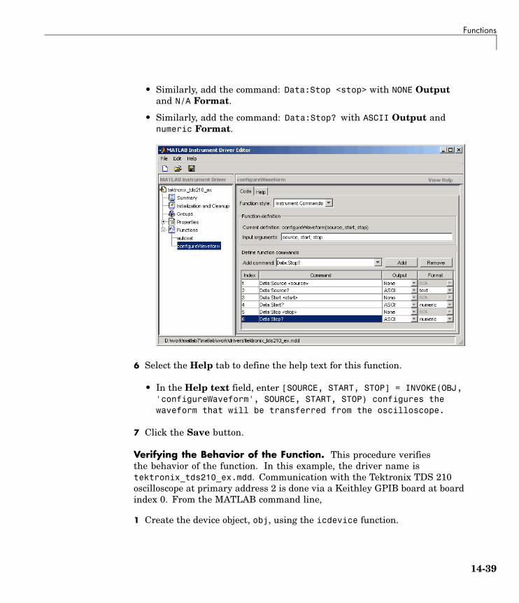
Functions
• Similarly, add the command: Data:Stop <stop> with NONE Outputand N/A Format.
• Similarly, add the command: Data:Stop? with ASCII Output andnumeric Format.
6 Select the Help tab to define the help text for this function.
• In the Help text field, enter [SOURCE, START, STOP] = INVOKE(OBJ,'configureWaveform', SOURCE, START, STOP) configures thewaveform that will be transferred from the oscilloscope.
7 Click the Save button.
Verifying the Behavior of the Function. This procedure verifiesthe behavior of the function. In this example, the driver name istektronix_tds210_ex.mdd. Communication with the Tektronix TDS 210oscilloscope at primary address 2 is done via a Keithley GPIB board at boardindex 0. From the MATLAB command line,
1 Create the device object, obj, using the icdevice function.
14-39

14 Using the Instrument Driver Editor
g = gpib('keithley', 0, 2);obj = icdevice('tektronix_tds210_ex.mdd', g);
2 View the method you created.
methods(obj)
Methods for class icdevice:
Contents error instrhwinfo openclass fieldnames instrnotify openvarclose get instrument propinfoconnect geterror invoke selftestctranspose horzcat isa setdelete icdevice isequal simdevicereset igetfield isetfield sizedisconnect inspect isvalid subsasgndisp instrcallback length subsrefdisplay instrfind methods vertcatend instrfindall neeq instrhelp obj2mfile
Driver specific methods for class icdevice:
autoset configureWaveform
3 View the help you wrote.
instrhelp(obj, 'configureWaveform')
[SOURCE, START, STOP] = INVOKE(OBJ, 'configureWaveform', SOURCE,START, STOP) configures the waveform that will be transferred fromthe oscilloscope.
4 Connect to your instrument and execute the function.
connect(obj)[source, start, stop] = invoke(obj, 'configureWaveform', 'CH1',1, 500)source =CH1
14-40

Functions
start =1
stop =500
[source, start, stop] = invoke(obj, 'configureWaveform', 'CH2',0, 3500)source =CH2
start =1
stop =2500
5 Disconnect from your instrument and delete the object.
disconnect(obj)delete([obj g])
Example: An M-Code Style FunctionThis example creates a function that will transfer and scale the waveform fromthe Tektronix TDS 210 oscilloscope. In the MATLAB instrument driver editor,
1 Select the Functions node in the tree.
2 Enter the function name, getWaveform, in the Add function text field andclick the Add button. The new function’s name, getWaveform, appears inthe Function Name table.
3 Expand the Functions node to display all the defined functions.
4 Select the getWaveform node from the functions displayed in the tree.
5 Select the Code tab to define commands executed for this function.
• Select M-Code in the Function style field.
14-41

14 Using the Instrument Driver Editor
• Update the function line in the Define MATLAB function text field toinclude an output argument.
function yout = getWaveform(obj)
• Add the following MATLAB code to the Define MATLAB function textfield. (The instrument may require a short pause before any statementsthat read a waveform, to allow its completion of the data collection.)
% Get the interface object.g = get(obj, 'Interface');
% Configure the format of the data transferred.fprintf(g, 'Data:Encdg SRIBinary');fprintf(g, 'Data:Width 1');
% Determine which waveform is being transferred.source = query(g, 'Data:Source?');
% Read the waveform.fprintf(g, 'Curve?');ydata = binblockread(g, 'int8');
% Read the trailing terminating character.fscanf(g);
% Scale the data.fprintf(g, ['WFMPre:' source ':Yoff?']);yoffset = fscanf(g, '%g');
fprintf(g, ['WFMPre:' source ':YMult?']);ymult = fscanf(g, '%g');
yout = (ydata*ymult) + yoffset;
14-42

Functions
6 Click the Help tab to define the help text for this function.
• In the Help text field, enter DATA = INVOKE(OBJ, 'getWaveform')transfers and scales the waveform from the oscilloscope.
7 Click the Save button.
14-43

14 Using the Instrument Driver Editor
Verifying the Behavior of the Function. This procedure verifiesthe behavior of the function. In this example, the driver name istektronix_tds210_ex.mdd. Communication with the Tektronix TDS 210oscilloscope at primary address 2 is done via a Keithley GPIB board at boardindex 0. From the MATLAB command line,
1 Create the device object, obj, using the icdevice function.
g = gpib('keithley', 0, 2);obj = icdevice('tektronix_tds210_ex.mdd', g);
2 View the method you created.
methods(obj)
Methods for class icdevice:
Contents error instrhwinfo openclass fieldnames instrnotify openvarclose get instrument propinfoconnect geterror invoke selftestctranspose horzcat isa setdelete icdevice isequal simdevicereset igetfield isetfield sizedisconnect inspect isvalid subsasgndisp instrcallback length subsrefdisplay instrfind methods vertcatend instrfindall neeq instrhelp obj2mfile
Driver specific methods for class icdevice:
autoset configureWaveform getWaveform
3 View the help you wrote.
instrhelp(obj, 'getWaveform')DATA = INVOKE(OBJ, 'getWaveform') transfers and scales thewaveform from the oscilloscope.
4 Connect to your instrument and execute the function.
14-44
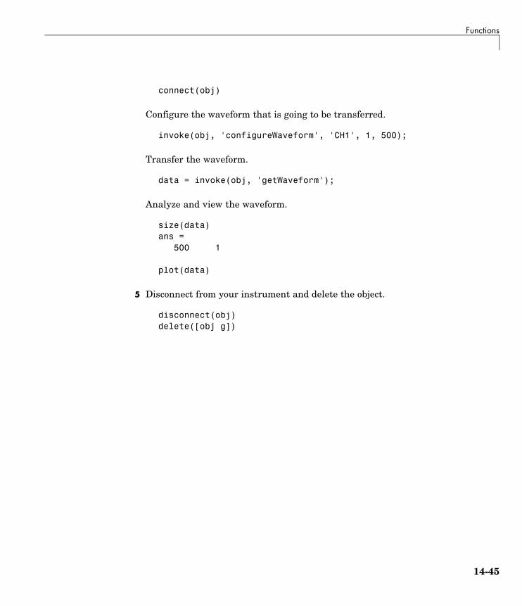
Functions
connect(obj)
Configure the waveform that is going to be transferred.
invoke(obj, 'configureWaveform', 'CH1', 1, 500);
Transfer the waveform.
data = invoke(obj, 'getWaveform');
Analyze and view the waveform.
size(data)ans =
500 1
plot(data)
5 Disconnect from your instrument and delete the object.
disconnect(obj)delete([obj g])
14-45

14 Using the Instrument Driver Editor
Groups
In this section...
“Group Components” on page 14-46
“Examples of Groups” on page 14-47
Group ComponentsA group may be used to set or query the same property on several elements, orto query several related properties, at the same time. For example, all inputchannels on an oscilloscope can be scaled to the same value with a singlecommand; or all current measurement setups can be retrieved and viewedat the same time.
A group consists of one or more group objects. The objects in the group sharea set of properties and functions. Using these properties and functions youcan control the features of the instrument represented by the group. Inorder for the group objects to control the instrument correctly, the groupmust define a selection command for the group and an identification stringfor each object in the group.
Selection CommandThe selection command is an instrument command that configures theinstrument to use the capability or physical component represented bythe current group object. Note, the instrument might not have a selectioncommand.
Identification StringThe identification string identifies an object in the group. The number ofidentification strings listed by the group defines the number of objects inthe group. The identification string can be substituted into the instrumentcommands written to the instrument.
When a group object instrument command is written to the instrument, thefollowing steps occur:
1 The selection command for the group is determined by the driver.
14-46

Groups
2 The identification string for the group object is determined by the driver.
3 If the selection command contains the string <ID>, it is replaced with theidentification string.
4 The selection command is written to the instrument. If empty, nothing iswritten to the instrument.
5 If the instrument command contains the string <ID>, it is replaced with theidentification string.
6 The instrument command is written to the instrument.
Examples of GroupsThis section includes several examples of groups, with steps to verify the code.
Example: Creating a One-Element GroupThis example combines the trigger capabilities of the Tektronix TDS 210oscilloscope into a trigger group. The oscilloscope allows the trigger sourceand slope settings to be configured. In the MATLAB instrument driver editor,
1 Select the Groups node in the tree.
2 Enter the group name, Trigger, in the New Group text field and clickAdd.
3 Expand the Groups node to display all the defined groups.
4 Select the Trigger node in the tree.
5 Select the Definition tab.
Since the oscilloscope has only one trigger, there is not a command thatwill select the current trigger. The Selection command text field willremain empty.
14-47

14 Using the Instrument Driver Editor
6 Select the Help tab to finish defining the group behavior.
In the Help text field, enter Trigger is a trigger group. Thetrigger group object contains properties that configure andquery the oscilloscope's triggering capabilities.
7 Click the Save button.
Verifying the Group Behavior. This procedure verifies thegroup information defined. In this example, the driver name istektronix_tds210_ex.mdd. Communication with the Tektronix TDS 210oscilloscope at primary address 2 is done via a Keithley GPIB board at boardindex 0. From the MATLAB command line,
1 Create the device object, obj, using the icdevice function.
g = gpib('keithley', 0, 2);obj = icdevice('tektronix_tds210_ex.mdd', g);
2 View the group you created. Note that the HwName property is the groupobject identification string.
get(obj)get(obj, 'Trigger')HwIndex: HwName: Type: Name:1 Trigger1 scope-trigger Trigger1
3 View the help.
14-48

Groups
instrhelp(obj, 'Trigger')TRIGGER (object) (read only)Trigger is a trigger group. The trigger group object containsproperties that configure and query the oscilloscope's triggeringcapabilities.
4 Delete the objects.
delete([obj g])
Example: Defining the Group Object Properties for aOne-Element GroupThis example defines the properties for the Trigger group object created inthe previous example. The Tektronix TDS 210 oscilloscope can trigger fromCH1 or CH2 when the data has a rising or falling slope.
First, the properties Source and Slope are added to the trigger group object.In the MATLAB instrument driver editor,
1 Expand the Trigger group node to display the group object’s propertiesand functions.
2 Select the Properties node to define the Trigger group object properties.
3 Enter the property name Source in the Add property text field and clickthe Add button
4 Enter the property name Slope in the Add property text field and clickthe Add button.
5 Expand the Properties node to display the group object’s properties.
Next, define the behavior of the Source property:
1 Select the Source node in the tree.
2 Select the Code tab to define the set and get commands for the Sourceproperty.
• Select Instrument Commands in the Property style field.
14-49

14 Using the Instrument Driver Editor
• Enter TRIGger:MAIn:EDGE:SOUrce? in the Get command text field.
• Enter TRIGger:MAIn:EDGE:SOUrce in the Set command text field.
3 Select the Property Values tab to define the allowed property values.
• Select String in the Data Type field.
• Select Enumeration in the Constraint field.
• Enter CH1 in the Add property value text field and click the Addbutton. Then enter CH1 in the Instrument Value table field.
• Similarly, add the enumeration: CH2, CH2.
4 Select the General tab to finish defining the property behavior.
• Enter CH1 in the Default value text field.
• Select never in the Read only field.
• In the Help text field, enter Specifies the source for the mainedge trigger.
Next, define the behavior of the Slope property:
1 Select the Slope node in the tree.
2 Select the Code tab to define the set and get commands for the Slopeproperty.
• Select Instrument Commands in the Property style field.
• Enter TRIGger:MAIn:EDGE:SLOpe? in the Get command text field.
• Enter TRIGger:MAIn:EDGE:SLOpe in the Set command text field.
3 Select the Property Values tab to define the allowed property values.
• Select String in the Data Type field.
• Select Enumeration in the Constraint field.
• Enter falling in the Add property value text field and click the Addbutton. Then enter FALL in the Instrument Value table field.
14-50

Groups
• Similarly add the enumeration: rising, RISe.
4 Select the General tab to finish defining the property behavior.
• Enter falling in the Default value text field.
• Select never in the Read only field.
• In the Help text field, enter Specifies a rising or falling slopefor the main edge trigger.
5 Click the Save button.
Verifying Properties of the Group Object in MATLAB. This procedureverifies the properties of the Trigger group object. In this example, the drivername is tektronix_tds210_ex.mdd. Communication with the Tektronix TDS210 oscilloscope at primary address 2 is done via a Keithley GPIB board atboard index 0. From the MATLAB command line,
1 Create the device object, obj, using the icdevice function.
14-51

14 Using the Instrument Driver Editor
g = gpib('keithley', 0, 2);obj = icdevice('tektronix_tds210_ex.mdd', g);
2 Extract the trigger group objects, t, from the device object.
t = get(obj, 'Trigger')HwIndex: HwName: Type: Name:1 Trigger1 scope-trigger Trigger1
3 View the current values for the properties of the trigger group object.Calling get on the object lists all its properties.
get(t)
4 Calling get on a specific property lists its current value.
get(t, {'Source', 'Slope'})ans =
'CH1' 'falling'
5 View the acceptable values for the properties of the group object. Callingset on the object lists all its settable properties.
set(t)
6 Calling set on a specific property lists the values to which you can setthe property.
set(t, 'Source')[ {CH1} | CH2 ]
set(t, 'Slope')[ {falling} | rising ]
7 Try setting the property to valid and invalid values.
set(t, 'Source', 'CH2', 'Slope', 'rising')get(t, {'Source', 'Slope'})ans =
'CH2' 'rising'set(t, 'Source', 'CH3')??? The 'CH3' enumerated value is invalid.
14-52

Groups
set(t, 'Slope', 'steady')??? The 'steady' enumerated value is invalid.
8 View the help you wrote.
instrhelp(t, 'Source')SOURCE [ {CH1} | CH2 ]Specifies the source for the main edge trigger.
instrhelp(t, 'Slope')SLOPE [ {falling} | rising ]Specifies a rising or falling slope for the main edge trigger.
9 List the group object characteristics that you defined in the PropertyValues and General tabs.
propinfo(t, 'Source')ans =
Type: 'string'Constraint: 'enum'
ConstraintValue: {2x1 cell}DefaultValue: 'CH1'
ReadOnly: 'never'InterfaceSpecific: 1
propinfo(t, 'Slope')ans =
Type: 'string'Constraint: 'enum'
ConstraintValue: {2x1 cell}DefaultValue: 'falling'
ReadOnly: 'never'InterfaceSpecific: 1
10 Connect to your instrument to verify the set and get code.
connect(obj)
14-53

14 Using the Instrument Driver Editor
Note When you issue the get function on the Source property for thetrigger object, the textronix_tds210_ex.mdd driver actually sends theTRIGger:MAIn:EDGE:SOUrce? command to the instrument.
get(t, 'Source')ans =CH1
Note When you issue the set function on the Slope property for thetrigger object, the textronix_tds210_ex.mdd driver actually sends theTRIGger:MAIn:EDGE:SLOpe RISe command to the instrument.
set(t, 'Slope', 'rising')
11 Disconnect from your instrument and delete the objects.
disconnect(obj)delete([obj g])
Example: Creating a Four-Element GroupThis example combines the measurement capabilities of the Tektronix TDS210 oscilloscope into a measurement group. The oscilloscope allows fourmeasurements to be taken at a time. In the MATLAB instrument drivereditor,
1 Select the Groups node in the tree.
2 Enter the group name, Measurement, in the Add group text field andclick Add.
3 Expand the Groups node to display all the defined groups.
4 Select the Measurement node in the tree.
5 Select the Definition tab.
14-54

Groups
• The oscilloscope does not define an instrument command that will definethe measurement that is currently being calculated. The Selectioncommand text field will remain empty.
• In the Identifier Name listing, change Measurement1 to Meas1 todefine the identification string for the first measurement group objectin the group.
• Enter the identifiers Meas2, Meas3, and Meas4 for the remainingmeasurement group objects by typing each in the Identifier text fieldand clicking Add after each.
6 Select the Help tab to finish defining the group behavior.
• In the Help text field, enter Measurement is an array ofmeasurement group objects. A measurement group objectcontains properties related to each supported measurement onthe oscilloscope.
7 Click the Save button.
Verifying the Group Behavior. This procedure verifies thegroup information defined. In this example, the driver name istektronix_tds210_ex.mdd. Communication with the Tektronix TDS 210oscilloscope at primary address 2 is done via a Keithley GPIB board at boardindex 0. From the MATLAB command line,
14-55

14 Using the Instrument Driver Editor
1 Create the device object, obj, using the icdevice function.
g = gpib('keithley', 0, 2);obj = icdevice('tektronix_tds210_ex.mdd', g);
2 View the group you created. Note that the HwName property is the groupobject get(obj).
get(obj, 'Measurement')
HwIndex: HwName: Type: Name:1 Meas1 scope-measurement Measurement12 Meas2 scope-measurement Measurement23 Meas3 scope-measurement Measurement34 Meas4 scope-measurement Measurement4
3 View the help.
instrhelp(obj, 'Measurement')MEASUREMENT (object) (read only)Measurement is an array of measurement group objects. Ameasurement group object contains properties related to eachsupported measurement on the oscilloscope.
4 Delete the objects.
delete([obj g])
Example: Defining the Group Object Properties for aFour-Element GroupThis example defines the properties for the Measurement group object createdin the previous example. The Tektronix TDS 210 oscilloscope can calculatethe frequency, mean, period, peak to peak value, root mean square, risetime, fall time, positive pulse width, or negative pulse width of the waveformof Channel 1 or Channel 2.
First, the properties MeasurementType, Source, Value, and Units will beadded to the Measurement group object.
1 Expand the Measurement group node to display the group object’s propertiesand methods.
14-56

Groups
2 Select the Properties node to define the Measurement group objectproperties.
3 Enter the property name MeasurementType in the Add property text fieldand click the Add button.
4 Enter the property name Source in the Add property text field and clickthe Add button.
5 Enter the property name Value in the Add property text field and clickthe Add button.
6 Enter the property name Units in the Add property text field and clickthe Add button.
7 Expand the Properties node to display the group object’s properties.
Next, define the behavior of the MeasurementType property:
1 Select the MeasurementType node in the tree.
2 Select the Code tab to define the set and get commands for theMeasurementType property.
14-57

14 Using the Instrument Driver Editor
• Select Instrument Commands in the Property style field.
• Enter Measurement:<ID>:Type? in the Get command text field.
• Enter Measurement:<ID>:Type in the Set command text field.
3 Select the Property Values tab to define the allowed property values.
• Select String in the Data Type field.
• Select Enumeration in the Constraint field.
• Enter frequency in the Add property value text field and click theAdd button. Then enter FREQuency in the Instrument Value table field.
• Add the enumeration: mean, MEAN.
• Add the enumeration: period, PERIod.
• Add the enumeration: pk2pk, PK2pk.
• Add the enumeration: rms, CRMs.
• Add the enumeration: riseTime, RISe.
• Add the enumeration: fallTime, FALL.
• Add the enumeration: posWidth, PWIdth.
• Add the enumeration: negWidth, NWIdth.
• Add the enumeration: none, NONE.
14-58

Groups
4 Select the General tab to finish defining the property behavior.
• Enter none in the Default value text field.
• Select never in the Read only field.
• In the Help text field, enter Specifies the measurement type.
Next, define the behavior of the Source property.
1 Select the Source node in the tree.
14-59
14 Using the Instrument Driver Editor
2 Select the Code tab to define the set and get commands for the Sourceproperty.
• Select Instrument Commands in the Property style field.
• Enter Measurement:<ID>:Source? in the Get command field.
• Enter Measurement:<ID>:Source in the Set command field.
3 Select the Property Values tab to define the allowed property values.
• Select String in the Data Type field.
• Select Enumeration in the Constraint field.
• Enter CH1 in the Add property value text field and click the Addbutton. Then enter CH1 in the Instrument Value table field.
• Similarly add the enumeration: CH2, CH2.
4 Select the General tab to finish defining the property behavior.
• Enter CH1 in the Default value text field.
• Select never in the Read only field.
• In the Help text field, enter Specifies the source of themeasurement.
Next, define the behavior of the Units property.
1 Select the Units node in the tree.
2 Select the Code tab to define the set and get commands for the Unitsproperty.
• Select Instrument Commands in the Property style field.
• Enter Measurement:<ID>:Units? in the Get command text field.
• Since the Units property is read-only, leave the Set command textfield empty.
14-60

Groups
3 Select the Property Values tab to define the allowed property values.
• Select String in the Data Type field.
• Select None in the Constraint field.
4 Select the General tab to finish defining the property behavior.
• Enter volts in the Default value text field.
• Select always in the Read only field.
• In the Help text field, enter Returns the measurement units.
Finally, define the behavior of the Value property.
1 Select the Value node in the tree.
2 Select the Code tab to define the set and get commands for the Valueproperty.
• Select Instrument Commands in the Property style field.
• Enter Measurement:<ID>:Value? in the Get command text field.
• Since the Value property is read-only, leave the Set command textfield empty.
3 Select the Property Values tab to define the allowed property values.
• Select Double in the Data Type field.
• Select None in the Constraint field.
4 Select the General tab to finish defining property behavior.
• Enter 0 in Default value field.
• Select always in the Read only field.
• In the Help text field, enter Returns the measurement value.
5 Click the Save button.
14-61

14 Using the Instrument Driver Editor
Verifying the Properties of the Group Object in MATLAB. Thisprocedure verifies the properties of the measurement group object. In thisexample, the driver name is tektronix_tds210_ex.mdd. Communicationwith the Tektronix TDS 210 oscilloscope at primary address 2 is done via aKeithley GPIB board at board index 0. From the MATLAB command line,
1 Create the device object, obj, using the icdevice function.
g = gpib('keithley', 0, 2);obj = icdevice('tektronix_tds210_ex.mdd', g);
2 Extract the measurement group objects, m, from the device object.
m = get(obj, 'Measurement')
HwIndex: HwName: Type: Name:1 Meas1 scope-measurement Measurement12 Meas2 scope-measurement Measurement23 Meas3 scope-measurement Measurement34 Meas4 scope-measurement Measurement4
3 View the current values for the properties of the first group object. Callingget on the object lists all its properties.
get(m(1))
4 Calling get on a specific property lists its current value.
get(m(1), {'MeasurementType', 'Source', 'Units', 'Value'})
ans ='none' 'CH1' 'volts' [0]
5 View the acceptable values for the properties of the group object. Callingset on the object lists all its settable properties.
set(m(1))
set(m(1), 'MeasurementType')[ frequency | period | {none} | mean | pk2pk | rms | riseTime |fallTime | posWidth | negWidth ]
14-62

Groups
set(m(1), 'Source')[ {CH1} | CH2 ]
6 Try setting the property to valid and invalid values.
set(m(1), 'Source', 'CH2')get(m(1), 'Source')ans =CH2set(m(1), 'Source', 'CH5')??? The 'CH5' enumerated value is invalid.
7 View the help you wrote.
instrhelp(m(1), 'Value')VALUE (double) (read only)Returns the measurement value.
8 List the group object characteristics that you defined in the PropertyValues and General tabs.
propinfo(m(1), 'Units')ans =
Type: 'string'Constraint: 'none'
ConstraintValue: []DefaultValue: 'volts'
ReadOnly: 'always'InterfaceSpecific: 1
9 Connect to your instrument to verify the set and get code.
connect(obj)
Note When you issue the get function on the MeasurementType property forthe first measurement object in the group, the textronix_tds210_ex.mdddriver actually sends the Measurement:Meas1:Type? command to theinstrument.
get(m(1), 'MeasurementType')
14-63

14 Using the Instrument Driver Editor
ans =frequency
Note When you issue the set function on the Source property for thesecond measurement object in the group, the textronix_tds210_ex.mdddriver actually sends the Measurement:Meas2:Source CH2 command tothe instrument.
set(m(2), 'Source', 'CH2')
10 Disconnect from your instrument and delete the objects.
disconnect(obj)delete([obj g])
14-64

Using Existing Drivers
Using Existing Drivers
In this section...
“Modifying MATLAB Instrument Drivers” on page 14-65
“Importing VXIplug&play and IVI Drivers” on page 14-66
Modifying MATLAB Instrument DriversIf a MATLAB instrument driver does not exist for your instrument, it maybe that a MATLAB instrument driver for an instrument similar to yoursdoes exist. Rather than creating a new MATLAB instrument driver, you maychoose to edit an existing MATLAB instrument driver. An existing MATLABinstrument driver can be opened in the MATLAB instrument driver editorwith the midedit function.
midedit('drivername')
Deleting an Existing Property, Function, or Group
1 Select the property, function, or group in the tree.
2 Select the Edit menu.
3 Select the Delete menu item.
Renaming an Existing Property, Function, or Group
1 Select the property, function, or group in the tree.
2 Select the Edit menu.
3 Select the Rename menu item.
Other Settings and TasksRefer to “Creating MATLAB Instrument Drivers” on page 14-5 for informationon
• Defining summary information
14-65

14 Using the Instrument Driver Editor
• Defining initialization and cleanup code
• Creating a new property
• Creating a new function
• Creating a new group
Importing VXIplug&play and IVI DriversThe MATLAB Instrument Driver Editor can import a VXIplug&play or IVIdriver. You can evaluate or set the driver’s functions and properties, and themodified driver can be saved for further use:
1 Open the MATLAB Instrument Driver Editor with midedit.
2 Click the File menu, and select Import.
The Import Driver dialog box appears, showing the installedVXIplug&play and IVI drivers.
3 Select the desired driver and click Import.
The MATLAB Instrument Driver Editor creates a MATLAB instrumentdriver based on the properties and/or functions in the original VXIplug&playor IVI driver. The editor displays the new driver’s summary information,groups, properties, and functions.
With the MATLAB Instrument Driver Editor, you can
14-66

Using Existing Drivers
• Create, delete, modify, or rename properties, functions, or groups
• Add M-code around instrument commands for analysis
• Add create, connect, and disconnect code
• Save the driver as a separate MATLAB VXIplug&play instrument driveror MATLAB IVI instrument driver
14-67

14 Using the Instrument Driver Editor
14-68
15
Using the InstrumentDriver Testing Tool
This chapter describes how to use the Instrument Driver Testing Tool to verifythe functionality of your instrument drivers.
Instrument Driver Testing Tool:Overview (p. 15-2)
An explanation of the MATLABInstrument Driver Testing Tool, itscapabilities, and usage.
Setting Up Your Test (p. 15-5) Providing global information for yourtest, including name, description,driver, interface, and preferences.
Defining Test Steps (p. 15-11) Creating steps to test settingproperty values, getting propertyvalues, and driver functions.
Saving Your Test (p. 15-25) Saving your test for future midtestsessions, or as M-code, or as a driverfunction.
Testing and Results (p. 15-28) Running a complete or partial test;exporting or saving test results.

15 Using the Instrument Driver Testing Tool
Instrument Driver Testing Tool: Overview
In this section...
“Functionality” on page 15-2
“Drivers” on page 15-2
“Test Structure” on page 15-3
“Starting” on page 15-3
“Example” on page 15-4
FunctionalityThis section provides an overview of the MATLAB Instrument Driver TestingTool and examples showing its capabilities and usage.
The MATLAB Instrument Driver Testing Tool provides a graphicalenvironment for creating a test to verify the functionality of a MATLABinstrument driver.
The MATLAB Instrument Driver Testing Tool provides a way to do thefollowing:
• Verify property behavior.
• Verify function behavior.
• Save the test as a test file, MATLAB code, or driver function.
• Export the test results to MATLAB workspace, figure window, MAT-file, orthe MATLAB array editor.
• Save test results as an HTML page.
DriversYou can use the MATLAB Instrument Driver Testing Tool to test anyMATLAB instrument driver, which include:
• MATLAB interface drivers
• MATLAB VXIplug&play drivers
15-2

Instrument Driver Testing Tool: Overview
• MATLAB IVI drivers
MATLAB VXIplug&play drivers and MATLAB IVI drivers can be createdfrom VXIplug&play and IVI drivers, respectively, using the MATLABInstrument Driver Editor or the makemid function.
Test StructureThe driver test structure is composed of setup information and test steps.
SetupWhen setting up or initializing the test, you provide a test name anddescription, identify the driver to test, define the interface to the instrument,and set the test preferences. This information remains unchanged throughoutthe execution of the test, and applies to every step.
Test StepsThe executable portion of the test is divided into any number of test steps.A test step can perform one of four verifications:
• Set property — Verify that the set command or set code of a single deviceobject or group object property in the driver does not error, and that thedriver supports the defined range for the property value. You can use onevalue or all supported values for the property. You may also use invalidproperty values to check the driver’s response.
• Get property — Verify the reading of a single device object or group objectproperty from the driver.
• Properties sweep — Verify several properties in a single step.
• Function — Verify the execution of a driver function.
After configuring your test steps, you can execute the steps individually, orrun a complete test that executes all the steps in the test.
StartingYou start the MATLAB Instrument Driver Testing Tool by typing theMATLAB command
15-3

15 Using the Instrument Driver Testing Tool
midtest
This opens the tool without any test file loaded.
You may specify a test file (usually created in an earlier session of the tool)when you start the tool so that it opens up with a test file already loaded.
midtest('MyDriverTestfile')
ExampleFor the examples in this chapter, you will create a test for the TektronixTDS210 oscilloscope driver that you created in Chapter 14, “Using theInstrument Driver Editor”.
You will create each kind of step in your test: set property, get property, sweepproperties, and function.
15-4

Setting Up Your Test
Setting Up Your Test
In this section...
“Test File” on page 15-5
“Providing a Name and Description” on page 15-5
“Specifying the Driver” on page 15-5
“Specifying an Interface” on page 15-5
“Setting Test Preferences” on page 15-6
“Example: Setting Up a Driver Test” on page 15-7
Test FileYou can specify a test file to load when you start midtest, open a test file afterthe MATLAB Instrument Driver Testing Tool is already up, or create a newtest. You may find it convenient to keep the driver and test file together in thesame directory. For easy use in the MATLAB Command Window, you can putthat directory in the MATLAB path with the addpath command.
Providing a Name and DescriptionThe Name field allows a one-line text definition for your test. This nameappears in the header of the test results in the Output Window.
The Description field allows a full definition of the text with as muchdescriptive text as you need.
Specifying the DriverIn the Driver text field, you specify the driver to be tested. This is anyMATLAB instrument driver, usually with the .mdd extension. Enter the fullpath to the driver, or click Browse to navigate to the driver’s directory.
Specifying an InterfaceYou specify the interface with the instrument for the testing of the driver.The instrument object type may be GPIB, VISA, TCPIP, UDP, or serial port.
15-5

15 Using the Instrument Driver Testing Tool
Depending on the type you choose, the New Object Creation dialog boxprompts you for further configuration information.
The tool then creates a device object based on interface and driver.
Setting Test PreferencesThe Test Preferences dialog box allows you to set certain behaviors of thetool when running a test.
Run ModeThis specifies whether the test runs all the steps or only one step in the test.
Fail ActionThis specifies what happens if a step within the test fails. The test may stopafter the failed step or continue, with or without resetting the instrument.
No-error StringThis field specifies the expected string returned from the instrumentwhen there is no error. If you indicate that a step passes when no error isreturned from the instrument, the tool compares the string returned fromthe instrument via the geterror function, to the string given here in thePreferences dialog box. If the strings match, then the tool assumes there is noerror from the instrument.
Number of Values to TestA double-precision property can be tested using all supported values. You canrequest this when testing it as a single step, or the tool does it automaticallywhen the property is tested as part of a property sweep step. This fieldspecifies how many values are tested for such a property.
The number of values includes the defined minimum and maximum for theproperty, and integer values equally spaced between these limits.
If your property requires noninteger values for testing, then create a separatetest step for that property instead of including it in a sweep.
15-6

Setting Up Your Test
Example: Setting Up a Driver TestThis example identifies the driver to be tested, and defines global setupinformation for the test. You will be testing the driver created in the examplesof Chapter 14, “Using the Instrument Driver Editor”.
1 Open the MATLAB Instrument Driver Testing Tool from the command linewith the command midtest.
2 In the Name text field, enter TDS 210 Driver Sample Test.
3 In the Description text field, enter A test to check some of theproperties and functions of the TDS 210 oscilloscope driver.
4 In the Driver field, enter the name of the driver you created in Chapter 14,“Using the Instrument Driver Editor”. The text field will display the wholepathname, with the driver file tektronix_tds210_ex.mdd.
5 Click the Create button to create an instrument interface.
15-7

15 Using the Instrument Driver Testing Tool
6 In the New Object Creation dialog box,
a Select your Instrument object type, Vendor, Board index, andPrimary address of your instrument.
The example illustrations in this chapter use a CEC GPIB board withindex 0 and the instrument at address 4. Your configuration may bedifferent.
b Click OK.
7 Click the File menu and select Test Preferences.
15-8

Setting Up Your Test
8 In the Test Preferences dialog box,
a For Select run mode, click Run all steps.
b For Select fail action, click Continue test.
c For Message returned from instrument when no error occurred,enter "". (This is an empty string in double quotes.)
d For Number of values to test for double properties, enter 5.
e Click OK.
15-9

15 Using the Instrument Driver Testing Tool
The MATLAB Instrument Driver Testing Tool now displays all your setupinformation.
9 Click File and select Save. Enter tektronix_tds210_ex_test as thefilename for your test. The tool automatically adds the .xml file extension.
15-10

Defining Test Steps
Defining Test Steps
In this section...
“Test Step: Set Property” on page 15-11
“Test Step: Get Property” on page 15-15
“Test Step: Properties Sweep” on page 15-17
“Test Step: Function” on page 15-21
Test Step: Set PropertyYou use a set property test step to verify a driver’s set code or set command fora property. You provide a name for the step, select the driver property to testand the values to test it with, and define the conditions for the step’s passing.
Settings Dscription
Name You provide a name for each test step. The name appearsin the Test Explorer tree as well as in the results output.
Property to Test A set property step can test only one property. You choosethe property from the Property to Test list. Additionalproperties can be tested with additional steps, or with asweep step.
Object(s) to Test A property may be defined for the instrument or for agroup object. If you are testing a group object property,you select which object you want tested in the Object(s)to Test list.
15-11

15 Using the Instrument Driver Testing Tool
Settings Dscription
Define theValues to Test
If the property is has enumerated values, you canselect one of the defined values, all of the supportedvalues, or some other value. If the property’s value is adouble-precision number, you can select a value withinits defined range, all supported values, or some othervalue. For a double, you set the number of values testedfor all supported values in the Preferences dialog box (see“Number of Values to Test” on page 15-6).
Select Whenthis Step Passes
The step passes when one or both of two conditions aremet:
• If no instrument or MATLAB error occurs as a resultof attempting to set the property with its test value
• If a query of the property after it is set returns aspecified value
If you select more than one of these conditions, then bothconditions must be met for the step to pass. If no boxesare selected, the test will pass.
Example: Creating a Test Step: Set Property
1 Click the Set Property option in the Test Steps list box.
2 Click the Add button.
3 In the Name field, enter Set Display Contrast.
4 In the Property to test list, select DisplayContrast.
5 For Define the value(s) to test, select All supported values.
6 For Select when this step passes,
• Select If no MATLAB or instrument error occurs.
• Select If current value matches configured value.
15-12

Defining Test Steps
7 Click File and select Save.
Running a Test Step to Set a PropertyYou can run an individual test step to verify its behavior:
1 Select Set Display Contrast in the Test Explorer tree.
2 With the cursor on the selected name, right-click to bring up the contextmenu.
3 In the context menu, select Run this step only.
15-13

15 Using the Instrument Driver Testing Tool
You may want to repeat this step as you observe the oscilloscope display.The test sets the display contrast to five different values: lowest acceptablevalue (1%), highest acceptable value (100%), and three approximately equallyspaced integer values between these limits.
The tool automatically displays the Output Window with the test results.
This test step passed because, for each of the five display contrast settings,the tool read back a value that was equal to the configured value.
15-14

Defining Test Steps
Test Step: Get PropertyYou use a get property test step to verify a driver’s ability to read a property.You provide a name for the step, select the driver property to test, and definethe conditions for the step’s passing.
SettingsThe settings for the get property step are the same as for a “Test Step: SetProperty” on page 15-11, except that instead of providing a value to write, youcan provide an output argument variable.
Output Argument. The test step assigns the optional output argumentvariable the value that results from reading the property. The variable isavailable for “Exporting Results” on page 15-30, after the test step hasexecuted.
Example: Creating a Test Step: Get Property
1 Click the Get Property option in the Test Step field.
2 Click the Add button.
3 In the Name field, enter Getting Display Contrast.
4 In the Property to test list, select DisplayContrast.
5 In the Output argument field, enter DispContr.
6 For Select when this step passes,
• Unselect the box for If no MATLAB or instrument error occurs.
• Select If property value is, and enter a value of 80.
This value is chosen to generate a failure. If this step follows theprevious step in the example, the display contrast is still set at 100. Ifthis step is run by itself, the display contrast is set to 50 by the *RSTcommand that is executed as part of your connect code for the driver.
15-15

15 Using the Instrument Driver Testing Tool
7 Click File and select Save.
15-16

Defining Test Steps
Running a Test Step to Get a PropertyYou run the individual test step to verify its behavior.
1 Select Get Display Contrast in the Test Explorer tree.
2 With the cursor on the selected name, click the right mouse button to bringup the context menu.
3 In the context menu, select Run this step only.
Note that the test fails, reading a value of 50 while expecting a value of 80.
Test Step: Properties SweepA properties sweep step allows you to test several properties in a single step.All selected properties are tested for all supported values. (In the case ofproperties with double-precision values, you determine the “Number of Valuesto Test” on page 15-6, in the Test Preferences dialog box.)
15-17

15 Using the Instrument Driver Testing Tool
SettingsThe fields for name and passing conditions are the same as other types oftest steps. The sweep step also requires that you select which propertiesand groups to test.
Select the Properties to Test. You may select any or all of the properties fortesting in a sweep step. You may find it convenient to create several sweepsteps for testing related groups properties together.
Select the Group Object to Use on Sweep. For those properties definedfor group objects, you can select a particular group object to test, or all thegroup objects. You can also define different sweep steps for different groupobjects.
Example: Creating a Sweep Step to Test All Properties
1 Click the Properties Sweep option in the Test Step field.
2 Click the Add button.
3 In the Name field, enter All Properties Sweep.
4 For Select the properties to test, click Select All.
5 In the Select the group object(s) field,
• For the Measurement group, select All Measurement group objects.
• For the Trigger group, select All Trigger group objects.
6 For Select when this step passes,
• Select If no MATLAB or instrument error occurs, and
• Select If current value matches configured value
7 Click File and select Save.
15-18

Defining Test Steps
Running a Sweep Step to Test All PropertiesYou run the sweep test step to verify its behavior.
1 Select All Properties Sweep in the Test Explorer tree.
2 With the cursor on the selected name, click the right mouse button to bringup the context menu.
3 In the context menu, select Run this step only.
15-19

15 Using the Instrument Driver Testing Tool
The Output Window is updated as each property in the sweep is tested.Note that the entire sweep is only one step in the overall test.
15-20

Defining Test Steps
Test Step: FunctionA function test step sends a function call to the instrument. You select thefunction called, the input data and output arguments (if required), and theconditions for passing.
Settings
Name. You provide a name for each test step. The name appears in the TestExplorer tree as well as in the results output.
Function to test. A function step can test only one function. You choose thefunction from the Function to test list. Additional functions can be testedwith additional steps.
Function definition. The tool displays below the selected function what thecall command for the function looks like. This helps you when deciding whatinput and output arguments to supply.
Input argument(s) and Output argument(s). You provide inputarguments as a comma-separated list of data, strings, or whatever thefunction is expecting.
You provide output argument variable for any data returned from the function.The output arguments can be used to determine if the test step passes, or for“Exporting Results” on page 15-30 after the test step has executed.
Select when this step passes. The step passes when any of threeconditions is met:
• If no instrument or MATLAB error occurs as a result of attempting toexecute the function
• If the returned output arguments match expected values
• If the output of a specified function is true
If you select more than one of these conditions, then all selected conditionsmust be met for the step to pass. If no boxes are selected, the test will pass.
15-21

15 Using the Instrument Driver Testing Tool
Example: Creating a Test Step: Function
1 Click the Function option in the Test Step field.
2 Click the Add button.
3 In the Name field, enter Config Waveform.
4 In the Function to test list, select configureWaveform.
5 In the Input argument(s) field, type 'CH1', 1, 3000.
6 In the Output argument(s) field, type Channel, StartAdr, StopAdr.
7 For Select when this step passes,
• Select If no MATLAB or instrument error occurs.
• Select If output arguments are, and enter in its field 'CH1', 1, 2500.
• Unselect If output of function ... is true.
8 Click File and select Save.
Note that you set the input argument for the stop address to 3000, but you setthe expected value for its output argument, StopAdr, to 2500. This is becausethe maximum address of the oscilloscope is 2500. If you attempt to exceedthat value, the oscilloscope address is set to the maximum.
15-22

Defining Test Steps
15-23

15 Using the Instrument Driver Testing Tool
Running a Test Step to Test a FunctionYou can run an individual test step to verify its behavior
1 Select Config Waveform in the Test Explorer tree.
2 With the cursor on the selected name, click the right mouse button to bringup the context menu.
3 In the context menu, select Run this step only.
15-24
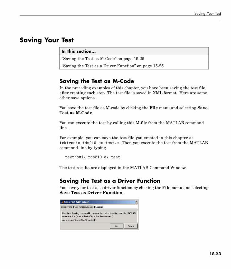
Saving Your Test
Saving Your Test
In this section...
“Saving the Test as M-Code” on page 15-25
“Saving the Test as a Driver Function” on page 15-25
Saving the Test as M-CodeIn the preceding examples of this chapter, you have been saving the test fileafter creating each step. The test file is saved in XML format. Here are someother save options.
You save the test file as M-code by clicking the File menu and selecting SaveTest as M-Code.
You can execute the test by calling this M-file from the MATLAB commandline.
For example, you can save the test file you created in this chapter astektronix_tds210_ex_test.m. Then you execute the test from the MATLABcommand line by typing
tektronix_tds210_ex_test
The test results are displayed in the MATLAB Command Window.
Saving the Test as a Driver FunctionYou save your test as a driver function by clicking the File menu and selectingSave Test as Driver Function.
15-25

15 Using the Instrument Driver Testing Tool
When you enter a name for the driver test function, the invoke command atthe bottom of the dialog box reflects that name. You use that invoke commandto execute the driver function from the MATLAB command line or in an M-file.
Example: Creating a Driver Test Function
1 Click the File menu and select Save Test as Driver Function.
2 Enter drivertest in the Specify the driver function name field.
3 Click OK.
A function called drivertest is created and saved as part of the instrumentdriver file. You can open the driver file in the MATLAB Instrument DriverEditor tool (midedit) to verify that the drivertest function is included.
Example: Calling a Driver Test Function from MATLABNow that the test function is included in the driver, you access it with theinvoke command from the MATLAB command line.
In the MATLAB Command Window,
1 Create an interface object.
g = gpib('cec',0,4)
2 Create a device object, specifying the driver with the drivertest functionsaved in it.
obj = icdevice('tektronix_tds210_ex.mdd',g)
3 Connect to the device.
connect(obj)
4 Execute the driver test.
out = invoke(obj, 'drivertest')
5 When the test is complete, disconnect from the instrument and delete theobjects.
15-26

Saving Your Test
disconnect(obj)delete ([g obj])
15-27

15 Using the Instrument Driver Testing Tool
Testing and Results
In this section...
“Running All Steps” on page 15-28
“Partial Testing” on page 15-30
“Exporting Results” on page 15-30
“Saving Results” on page 15-31
Running All StepsSo far in this chapter, you have only run individual test steps after each wascreated.
When you run the entire test, all the test steps run in the order listed in theTest Explorer tree. Using the mouse, you may drag the nodes of the tree toalter their sequence.
The Output Window displays the results of each step, along with a finalresult of the complete test.
Example: Running a Complete Test
1 Select Get Display Contrast in the Test Explorer tree.
2 In the Select when this step passes field, change the If property valueis entry from 80 to 100.
Earlier you entered a value of 80 to illustrate what a failure looks like. Thedisplay contrast is left at 100 from the Set Display Contrast test step,so that is what you will test for in the next step.
3 Click File and select Save.
4 Click the green arrow button to start a test run.
15-28

Testing and Results
15-29

15 Using the Instrument Driver Testing Tool
Partial TestingUsing the context menu in the Test Explorer tree, you can run a partialtest of either an individual test step, or from the chosen test step throughthe end of the test.
Exporting ResultsYou can export the test results to many locations:
• MATLAB workspace
• MATLAB figure window
• MAT-file
• MATLAB Array Editor
The results you can export are those assigned to output variables in thesettings for a test step.
Example: Exporting Test Results to the MATLAB Workspace
1 Click the File menu and select Export Test Results.
2 In the Test Results Exporter dialog box, select MATLAB Workspace as theData destination.
By default, all the variables are selected. You may unselect any.
3 Click the Export button.
15-30

Testing and Results
The variables are now available in the MATLAB workspace, with valuesthat were established by the test run.
Saving ResultsYou save your test results in an HTML file by clicking the File menu andselecting Save Test Results. The format of the results in this file reflectstheir appearance in the tester tool’s Output Window.
15-31

15 Using the Instrument Driver Testing Tool
15-32

16
Using the InstrumentControl Toolbox BlockLibrary
Instrument Control Toolbox includes a Simulink® interface called theInstrument Control Toolbox block library. You can use the blocks of thislibrary in a Simulink model to communicate with an instrument.
Overview (p. 16-2) Introduces the Instrument ControlToolbox block library
Opening the Instrument ControlBlock Library (p. 16-3)
Describes how to access the blocklibrary
Building Simulink Models to Sendand Receive Data (p. 16-6)
Examples of using InstrumentControl blocks.

16 Using the Instrument Control Toolbox Block Library
OverviewThis chapter describes how to use the Instrument Control Toolbox blocklibrary. The Instrument Control Toolbox block library consists of six blocks:
• Query Instrument — Query the instrument for data.
• To Instrument — Send data to the instrument.
• TCPIP Receive — Receive data over a TCP/IP network.
• TCPIP Send — Send data over TCP/IP network.
• UDP Receive — Receive data over UDP network.
• UDP Send — Send data over UDP network.
The Instrument Control Toolbox block library is a tool for sending live datafrom your model to an instrument, or querying an instrument to receive livedata into your model. You can use blocks from the block library with blocksfrom other Simulink libraries to create sophisticated models.
To use the Instrument Control Toolbox block library you require Simulink,a tool for simulating dynamic systems. Simulink is a model definitionenvironment. Use Simulink blocks to create a block diagram that representsthe computations of your system or application. Simulink is also a modelsimulation environment. Run the block diagram to see how your systembehaves. If you are new to Simulink, read Getting Started with Simulink inthe Simulink documentation to better understand its functionality.
For more detailed information about the blocks in the Instrument ControlToolbox block library, see Blocks — Alphabetical List . For example for usingthe Instrument Control Toolbox block library, see “Building Simulink Modelsto Send and Receive Data” on page 16-6.
16-2

Opening the Instrument Control Block Library
Opening the Instrument Control Block Library
In this section...
“Using the instrumentlib Command from MATLAB” on page 16-3
“Using the Simulink Library Browser” on page 16-4
Using the instrumentlib Command from MATLABTo open the Instrument Control block library, enter
instrumentlib
at the MATLAB prompt. MATLAB displays the contents of the library in aseparate window.
16-3

16 Using the Instrument Control Toolbox Block Library
Using the Simulink Library BrowserTo open the Instrument Control Toolbox block library, start the SimulinkLibrary Browser and select the library from the list of available block librariesdisplayed in the browser.
To start the Simulink Library Browser, enter
simulink
at the MATLAB prompt. MATLAB opens the browser window. The left panelists available block libraries, with the basic Simulink library listed first,followed by other libraries listed in alphabetical order under it. To open theInstrument Control Toolbox block library, click its icon.
16-4

Opening the Instrument Control Block Library
Simulink loads the library and displays the blocks in the library.
16-5

16 Using the Instrument Control Toolbox Block Library
Building Simulink Models to Send and Receive Data
In this section...
“Example: Sending and Receiving Data Through a Serial Port Loopback”on page 16-6
“Example: Sending and Receiving Data Via a TCP/IP Network” on page16-16
Example: Sending and Receiving Data Through aSerial Port LoopbackThis section provides an example that builds a simple model using theInstrument Control blocks in conjunction with other blocks in the Simulinklibrary. The example illustrates how to send data to a simple loopback deviceconnected to the computer’s COM1 serial port and to read that data backinto your model.
You will use the To Instrument block to write a value to the serial port onyour computer, and then use the Query Instrument block to read that samevalue back into your model.
• “Step 1: Open the Block Library” on page 16-6
• “Step 2: Create a New Model” on page 16-7
• “Step 3: Drag the Instrument Control Toolbox Blocks into the Model” onpage 16-7
• “Step 4: Drag Other Blocks to Complete the Model” on page 16-8
• “Step 5: Connect the Blocks” on page 16-10
• “Step 6: Specify the Block Parameter Values” on page 16-11
• “Step 7: Run the Simulation” on page 16-14
Step 1: Open the Block LibraryTo open the Instrument Control Toolbox block library, start the SimulinkLibrary Browser and choose Instrument Control Toolbox from the list ofavailable libraries displayed in the browser.
16-6

Building Simulink Models to Send and Receive Data
To start the Simulink Library Browser, enter
simulink
at the MATLAB prompt. In the Simulink Library Browser the left panelists the available block libraries. To open the Instrument Control Toolboxblock library, click its entry icon. See “Using the Simulink Library Browser”on page 16-4 for more information.
Step 2: Create a New ModelTo use a block, you must add it to an existing model or create a new model.
For this example create a new model by clicking the Create a new modelbutton on the toolbar.
You can also click the File menu in the Simulink Library Browser and selectNew > Model. Simulink opens an empty model window on the display. Toassign the new model a name, use the Save option.
Step 3: Drag the Instrument Control Toolbox Blocks into theModelTo use the blocks in a model, click a block in the library and, holding themouse button down, drag it into the model window. For this example, you willneed one instance of the To Instrument and the Query Instrument block inyour model.
16-7

16 Using the Instrument Control Toolbox Block Library
Drag Instrument Control Toolbox Blocks into Model Window
Step 4: Drag Other Blocks to Complete the ModelThis example requires two more blocks. One block provides the data that issent to the instrument; the other block displays the data received from theinstrument.
Because the data sent to the instrument will be a constant, you can use theConstant block for this purpose. To access the Constant block, expand theSimulink node in the browser tree, and click on the Source library entry. From
16-8

Building Simulink Models to Send and Receive Data
the blocks displayed in the right pane, drag the Constant block into the modeland place it to the left of the To Instrument block.
Drag Constant Block to Model Window
To display the data received from the instrument, you can use the Displayblock. To access the Display block, click the Sinks library entry in theexpanded Simulink node in the browser tree. From the blocks displayed inthe right pane, drag the Display block into the model and place it to the rightof the Query Instrument block.
16-9

16 Using the Instrument Control Toolbox Block Library
Drag Display Block to Model Window
Step 5: Connect the BlocksMake a connection between the Constant block and the To Instrument block.When you move the pointer near the output port of the Constant block, thepointer become a cross hair. Click on the Constant output port and holdingthe mouse button, drag the pointer to the input port of the To Instrumentblock, and release the button.
In the same way, make the connection between the output port of the QueryInstrument block and the input port of the Display block.
16-10

Building Simulink Models to Send and Receive Data
Note The two blocks do not directly connect together within the model.The only communication between them is through the instrument, which isthe loopback connected to the COM1 serial port. Because there is no directconnection between these two blocks, you must consider their timing whenrunning the model. The Query Instrument block does not get its input fromthe To Instrument block, so it has no way to know when the data from theinstrument is available. Therefore, you must set the block parameters towrite the data to the loopback before the model attempts to receive data fromthe loopback.
Step 6: Specify the Block Parameter ValuesYou set parameters for the blocks in your model by double-clicking on theblock.
Configure the To Instrument Block. Double-click the To Instrument blockto open its parameters dialog box. Set the block sample time to 0.8. In theHardware Configuration tab, specify new hardware configuration with thevalues shown in the following figure.
16-11

16 Using the Instrument Control Toolbox Block Library
The model uses the default values on the Instrument Initialization andSend tabs of this block, so you do not need to modify any of their values.
Click Apply, then OK.
Configure the Query Instrument Block. Double-click the QueryInstrument block to open its parameters dialog box. Set the block sampletime to 1. Note that this time is slightly longer than the setting for the ToInstrument block. This is to assure that the To Instrument is complete inwriting data to the loopback before the Query Instrument block reads it.
In the Hardware Configuration tab, specify new a hardware configurationwith values to match the settings in the To Instrument block as shown inthe following figure.
16-12
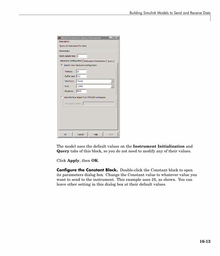
Building Simulink Models to Send and Receive Data
The model uses the default values on the Instrument Initialization andQuery tabs of this block, so you do not need to modify any of their values.
Click Apply, then OK.
Configure the Constant Block. Double-click the Constant block to openits parameters dialog box. Change the Constant value to whatever value youwant to send to the instrument. This example uses 25, as shown. You canleave other setting in this dialog box at their default values.
16-13

16 Using the Instrument Control Toolbox Block Library
Click Apply, then OK.
Configure the Display Block. For the Display block, you can use its defaultparameters.
Step 7: Run the SimulationTo run the simulation, click the Start button on the model window toolbar.Alternatively, you can use the Simulation menu in the model window andchoose the Start option.
When you run the simulation, th constant value you specified (25) is writtento the instrument (the serial loopback), received from the instrument, andshown in the Display block.
16-14

Building Simulink Models to Send and Receive Data
While the simulation is running, the status bar at the bottom of the modelwindow updates the progress of the simulation.
16-15

16 Using the Instrument Control Toolbox Block Library
Example: Sending and Receiving Data Via a TCP/IPNetworkThis section provides an example that builds a simple model using theInstrument Control blocks in the block library in conjunction with otherblocks in the Simulink library. This example illustrates how to send data toan echo server using TCP/IP and to read that data back into your model.
You will create an echo server on your machine that will simulate sending asignal to the TCP/IP send block and echo the result back to the Send blockto send data, and then use the TCP/IP Receive block to read that same databack into your model.
• “Step 1: Create an Echo Server” on page 16-16
• “Step 2: Open the Block Library” on page 16-17
• “Step 3: Create a New Model” on page 16-17
• “Step 4: Drag the Instrument Control Toolbox Blocks into the Model” onpage 16-17
• “Step 5: Drag Other Blocks to Complete the Model” on page 16-18
• “Step 6: Connect the Blocks” on page 16-20
• “Step 7: Specify the Block Parameter Values” on page 16-21
• “Step 8: Specify the Block Priorities” on page 16-23
• “Step 9: Run the Simulation” on page 16-26
• “Step 10: View the Result” on page 16-27
Step 1: Create an Echo ServerYou should first open a port on your computer that will work as an echo serverthat you can use to send and receive signals via TCP/IP. To create an echoserver type the following command in MATLAB:
echotcpip('on', 50000)
This will open port 50000 on your machine to work as an echo server andturn it on.
16-16

Building Simulink Models to Send and Receive Data
Step 2: Open the Block LibraryTo open the Instrument Control Toolbox block library, start the SimulinkLibrary Browser and choose Instrument Control Toolbox from the list ofavailable libraries displayed in the browser.
To start the Simulink Library Browser, enter
simulink
at the MATLAB prompt. In the Simulink Library Browser the left panelists the available block libraries. To open the Instrument Control Toolboxblock library, click its entry icon. See “Using the Simulink Library Browser”on page 16-4 for more information.
Step 3: Create a New ModelTo use a block, you must add it to an existing model or create a new model.
For this example, create a new model by clicking the Create a new modelbutton on the toolbar.
You can also click the File menu in the Simulink Library Browser and selectNew > Model. Simulink opens an empty model window on the display. Toassign the new model a name, use the Save option.
Step 4: Drag the Instrument Control Toolbox Blocks into theModelTo use the blocks in a model, click each block in the library and, holding themouse button down, drag it into the model window. For this model, youwill need one instance of the TCP/IP Send and the TCP/IP Receive block inyour model.
16-17

16 Using the Instrument Control Toolbox Block Library
Drag Instrument Control Toolbox Blocks into Model Window
Step 5: Drag Other Blocks to Complete the ModelThis example requires two more blocks. One block displays the data receivedfrom the receive block and the other block is the data to be sent to the sendblock.
The TCP/IP Send block needs a data source for data to be sent. Add the SineWave block to the model to send signals to the TCP/IP Send block. To access
16-18

Building Simulink Models to Send and Receive Data
the Sine Wave block, expand the Simulink node in the browser tree, andclick on the Sources library entry. From the blocks displayed in the rightpane, drag the Sine Wave block into the model and place it to the left of theTCP/IP Send block.
Drag Sine Wave Block to Model Window
To display the data received by the TCP/IP Receive block, you can use theScope block. To access the Scope block, click the Siping nks library entry inthe expanded Simulink node in the browser tree. From the blocks displayed
16-19

16 Using the Instrument Control Toolbox Block Library
in the right pane, drag the Display block into the model and place it to theright of the Query Instrument block.
Drag Scope Block to Model Window
Step 6: Connect the BlocksMake a connection between the Sine Wave block and the TCP/IP Send block.When you move the pointer near the output port of the Sine Wave block, thepointer becomes a cross hair. Click on the Sine Wave output port and holding
16-20

Building Simulink Models to Send and Receive Data
the mouse button, drag the pointer to the input port of the TCP/IP Send block,and release the button. In the same way, make the connection between theoutput port of the TCP/IP Receive block and the input port of the Scope block.
The two Instrument Control Toolbox blocks do not directly connect togetherwithin the model. You should therefore, set the block Priority to specify theorder of execution of the blocks. Without the priorities specified, there is achance that, during simulation the Receive block can run before the Sendblock. See “Step 8: Specify the Block Priorities” on page 16-23, for moreinformation.
Step 7: Specify the Block Parameter ValuesYou set parameters for the blocks in your model by double-clicking on theblock.
Configure the Send Block. Double-click the TCP/IP Send block to open itsparameters dialog box. Set the Remote address field to localhost and thePort field to 50000.
16-21

16 Using the Instrument Control Toolbox Block Library
Click Apply and then OK.
Configure the Receive Block. Double-click the Receive block to open itsparameters dialog box. Set the Remote address field to localhost and thePort field to 50000. Change the Data type to Double and the Block sampletime to 0.1.
16-22

Building Simulink Models to Send and Receive Data
Click OK.
Configure the Sine Wave Block. Double-click on the Sine Wave to open itsparameters dialog box. Set the Sample time to 0.1.
Click OK.
Step 8: Specify the Block PrioritiesIn order for the simulation to run correctly, you should specify the order inwhich Simulink should process the blocks. To do this you should set blockpriority from the Block Properties dialog box.
Note It is essential that you set the correct priority for the blocks in yourmodel, otherwise your simulation will fail.
• Right-click on the Sine Wave block and select Block Properties fromthe pop-up menu.
16-23

16 Using the Instrument Control Toolbox Block Library
In the Block Properties dialog box, enter 1 in the Priority field. This tellsSimulink to run this block first.
16-24

Building Simulink Models to Send and Receive Data
Click Apply and then OK.
• Right-click on the TCP/IP Send block and select Block Properties fromthe pop-up menu.
In the Block Properties dialog box, enter 2 in the Priority field. This tellsSimulink to run the block second.
Click Apply and then OK.
• Right-click on the TCP/IP Receive block and select Block Properties fromthe pop-up menu.
In the Block Properties dialog box, enter 3 in the Priority field. This tellsSimulink to run the block third.
Click Apply and then OK.
16-25

16 Using the Instrument Control Toolbox Block Library
• Right-click on the Scope block and select Block Properties from the pop-upmenu.
In the Block Properties dialog box, enter 4 in the Priority field. This tellsSimulink to run the block fourth.
Click Apply and then OK.
Read Working with Block Parameters in the Simulink User Guide tounderstand more about block priorities.
Step 9: Run the SimulationTo run the simulation, click Start on the model window toolbar. Alternatively,you can use the Simulation menu in the model window and choose the Startoption.
While the simulation is running, the status bar at the bottom of the modelwindow updates the progress of the simulation.
16-26

Building Simulink Models to Send and Receive Data
Step 10: View the ResultYou can double-click the Scope block to view the signal on a graph as it isreceived by the TCP/IP Receive block.
16-27

16 Using the Instrument Control Toolbox Block Library
16-28

17
Functions — By Category
Instrument Object Creation (p. 17-2) Create interface objects and deviceobjects
State Change (p. 17-2) Connect to instruments, disconnectfrom instruments, and recordinformation to disk
Property Display and Configuration(p. 17-3)
Return properties, configureproperties, and open propertyinspector
Reading Data (p. 17-3) Read text, binary, and binblock datafor interface objects
Writing Data (p. 17-4) Write text, binary, and binblock datafor interface objects
Information and Help (p. 17-5) Return function help, property help,and property characteristics
Graphical Tools (p. 17-5) Tools that facilitate instrumentcontrol in graphical environment
General Purpose (p. 17-6) Delete, clear, find, save, and loadobjects, convert objects to M-code
Interface Objects (p. 17-7) Functions listed by interface type(GPIB, VISA-VXI, and so on)
Device Objects (p. 17-10) Functions used only with deviceobjects
IVI Configuration Store Objects(p. 17-10)
Functions used only with IVIconfiguration store objects

17 Functions — By Category
Instrument Object Creation
Interface Object (p. 17-2) Create interface object
Device Object (p. 17-2) Create device object
Interface Object
gpib Create GPIB object
serial Create serial port object
tcpip Create TCPIP object
udp Create UDP object
visa Create VISA object
Device Object
icdevice Create device object
State Change
Interface Object (p. 17-3) Control interface object
Device Object (p. 17-3) Control device object
17-2

Property Display and Configuration
Interface Object
fclose Disconnect interface object frominstrument
fopen Connect interface object toinstrument
record Record data and event informationto file
Device Object
connect Connect device object to instrument
disconnect Disconnect device object frominstrument
Property Display and Configurationget Instrument object properties
inspect Open Property Inspector
set Configure or display instrumentobject properties
Reading Databinblockread Read binblock data from instrument
fgetl Read line of text from instrumentand discard terminator
fgets Read line of text from instrumentand include terminator
17-3

17 Functions — By Category
flushinput Remove data from input buffer
fread Read binary data from instrument
fscanf Read data from instrument, andformat as text
query Write text to instrument, and readdata from instrument
readasync Read data asynchronously frominstrument
scanstr Read data from instrument, formatas text, and parse
stopasync Stop asynchronous read and writeoperations
Writing Databinblockwrite Write binblock data to instrument
flushoutput Remove data from output buffer
fprintf Write text to instrument
fwrite Write binary data to instrument
query Write text to instrument, and readdata from instrument
stopasync Stop asynchronous read and writeoperations
17-4

Information and Help
Information and Helpinstrhelp Help for instrument object type,
function, or property
instrhwinfo Information about availablehardware
propinfo Instrument object propertyinformation
Graphical Tools
Interface Object (p. 17-5) Graphical tools for interface objects
Device Object (p. 17-5) Graphical tools for device objects
Interface Object
tmtool Open Test & Measurement Tool
Device Object
midedit Open graphical tool for creating andediting MATLAB instrument driver
midtest Open graphical tool for testingMATLAB instrument driver
tmtool Open Test & Measurement Tool
17-5

17 Functions — By Category
General Purposeclear Remove instrument objects from
MATLAB workspace
delete Remove instrument objects frommemory
disp Display instrument object summaryinformation
instrcallback Display event information whenevent occurs
instrfind Read instrument objects frommemory to MATLAB workspace
instrfindall Find visible and hidden instrumentobjects
instrid Define and retrieve commands thatidentify instruments
instrnotify Define notification for instrumentevents
instrreset Disconnect and delete all instrumentobjects
isvalid Determine whether instrumentobjects are valid
length Length of instrument object array
load Load instrument objects andvariables into MATLAB workspace
methods Class method names anddescriptions
obj2mfile Convert instrument object toMATLAB code
save Save instrument objects andvariables to MAT-file
size Size of instrument object array
17-6

Interface Objects
Interface Objects
GPIB (p. 17-7) Create GPIB object, clear instrumentbuffer, send trigger message, performserial poll
Serial Port (p. 17-8) Create serial port object, send breakto instrument
TCP/IP (p. 17-8) Create TCP/IP object, return hostinformation, start or stop echo server
UDP (p. 17-8) Create UDP object, return hostinformation, start or stop echo server
VISA-GPIB (p. 17-8) Create VISA-GPIB object, clearinstrument buffer, send triggermessage
VISA-GPIB-VXI (p. 17-8) Create VISA-GPIB-VXI object, lowlevel memory operations, high levelmemory operations, send trigger
VISA-Serial (p. 17-9) Create VISA-Serial object
VISA-VXI (p. 17-9) Create VISA-VXI object, low levelmemory operations, high levelmemory operations, send trigger
GPIB
clrdevice Clear instrument buffer
gpib Create GPIB object
spoll Perform serial poll
trigger Send trigger message to instrument
17-7

17 Functions — By Category
Serial Port
serial Create serial port object
serialbreak Send break to instrument
TCP/IP
echotcpip Start or stop TCP/IP echo server
resolvehost Network name or network address
tcpip Create TCPIP object
UDP
echoudp Start or stop UDP echo server
resolvehost Network name or network address
udp Create UDP object
VISA-GPIB
clrdevice Clear instrument buffer
trigger Send trigger message to instrument
visa Create VISA object
VISA-GPIB-VXI
clrdevice Clear instrument buffer
memmap Map memory for low-level memoryread and write operations
mempeek Low-level memory read from VXIregister
17-8

Interface Objects
mempoke Low-level memory write to VXIregister
memread High-level memory read from VXIregister
memunmap Unmap memory for low-levelmemory read and write operations
memwrite High-level memory write to VXIregister
visa Create VISA object
VISA-Serial
visa Create VISA object
VISA-VXI
clrdevice Clear instrument buffer
memmap Map memory for low-level memoryread and write operations
mempeek Low-level memory read from VXIregister
mempoke Low-level memory write to VXIregister
memread High-level memory read from VXIregister
memunmap Unmap memory for low-levelmemory read and write operations
memwrite High-level memory write to VXIregister
trigger Send trigger message to instrument
visa Create VISA object
17-9

17 Functions — By Category
Device Objectsdevicereset Reset instrument
geterror Check and return error messagefrom instrument
invoke Execute driver-specific function ondevice object
makemid Convert driver to MATLABinstrument driver format
selftest Run instrument self-test
IVI Configuration Store Objectsadd Add entry to IVI configuration store
object
commit Save IVI configuration store objectto data file
iviconfigurationstore Create IVI configuration store object
remove Remove entry from IVI configurationstore object
update Update entry of IVI configurationstore object
17-10

18
Functions — AlphabeticalList

add
Purpose Add entry to IVI configuration store object
Syntax add(obj, 'type', 'name', ...)add(obj, 'Driversession', 'name', 'ModuleName',
'HardwareAssetName', 'P1', V1)add(obj, 'HardwareAsset', 'name', 'IOResourceDescriptor',
'P1', V1)add(obj, 'LogicalName', 'name', 'SessionName', 'P1', V1)add(obj, struct)
Arguments obj IVI configuration store object
'DriverSession''HardwareAsset''LogicalName'
Type of entry being added
'name' Name of the DriverSession,HardwareAsset, or LogicalNamebeing added
'IOResourceDescriptor' Tells the driver exactly how to locate thedevice this asset represents
'ModuleName' IVI instrument driver or software module
'HardwareAssetName' Unique identifier for hardware asset
'SessionName' Unique identifier for asset driver session
'P1' First optional parameter for added entry.Other parameter-value pairs may follow.
V1 Value for first parameter
struct Structure defining entry to be added; fieldnames are the entry parameter names
Description add(obj, 'type', 'name', ...) adds a new entry of type to the IVIconfiguration store object, obj, with name, name. If an entry of type,type, with name, name, already exists an error will occur. Based on
18-2

add
type, additional arguments are required. type can be HardwareAsset,DriverSession, or LogicalName.
add(obj, 'Driversession', 'name', 'ModuleName','HardwareAssetName', 'P1', V1) adds a new driver session entryto the IVI configuration store object, obj, with name, name, using thespecified software module name, ModuleName and hardware asset name,HardwareAssetName. Optional parameter-value pairs may be included.
Valid parameters for DriverSession are listed below. The default valuefor on/off parameters is off.
Parameter Value Description
Description Any string Description of driver session
VirtualNames structure A struct array containingvirtual name mappings
Cache on/off Enable caching if the driversupports it.
DriverSetup Any string This value is software moduledependent
InterchangeCheck on/off Enable driverinterchangeability checking, ifsupported
QueryInstrStatus on/off Enable instrument statusquerying by the driver
RangeCheck on/off Enable extended range checkingby the driver, if supported
RecordCoercions on/off Enable recording of coercions bythe driver, if supported
Simulate on/off Enable simulation by the driver
add(obj, 'HardwareAsset', 'name', 'IOResourceDescriptor','P1', V1) adds a new hardware asset entry to the IVI configurationstore object, obj, with name, name, and resource descriptor,
18-3

add
IOResourceDescriptor. Optional parameter-value pairs may beincluded.
Valid parameters for HardwareAsset are
Parameter Value Description
Description Any string Description of hardware asset
add(obj, 'LogicalName', 'name', 'SessionName', 'P1', V1) addsa new logical name entry to the IVI configuration store object, obj,with name, name, and driver session name, SessionName. Optionalparameter-value pairs may be included.
Valid parameters for LogicalName are
Parameter Value Description
Description Any string Description of logical name
add(obj, struct), where struct is a structure whose field names arethe entry parameter names, adds an entry to the IVI configurationstore object, obj, of the specified type with the values contained in thestructure.
Additions made to the configuration store object, obj, can be saved tothe configuration store data file with the commit function.
Examples Construct IVI configuration store object, c.
c = iviconfigurationstore;
Add a hardware asset with name gpib1, and resource descriptionGPIB0::1::INSTR.
add(c, 'HardwareAsset', 'gpib1', 'GPIB0::1::INSTR');
Add a driver session with name S1, that uses the TekScope softwaremodule and the hardware asset with name gpib1.
18-4

add
add(c, 'DriverSession', 'S1', 'TekScope', 'gpib1');
Add a logical name to configuration store object c, with name MyScope,driver session name S1, and description A logical name.
add(c, 'LogicalName', 'MyScope', 'S1', ...'Description', 'A logical name');
Add a hardware asset with the name gpib3, and resource descriptionGPIB0::3::ISNTR.
s.Type = 'HardwareAsset';s.Name = 'gpib3';s.IOResourceDescriptor = 'GPIB0::3::INSTR';add(c, s);
Save the changes to the IVI configuration store data file.
commit(c);
See Also Functions
iviconfigurationstore, iviconfigurationstore/commit,iviconfigurationstore/remove, iviconfigurationstore/update
18-5

binblockread
Purpose Read binblock data from instrument
Syntax A = binblockread(obj)A = binblockread(obj,'precision')[A,count] = binblockread(...)[A,count,msg] = binblockread(...)
Arguments obj An interface object.
'precision' The number of bits read for each value, and theinterpretation of the bits as character, integer, orfloating-point values.
A Binblock data returned from the instrument.
count The number of values read.
msg A message indicating if the read operation wasunsuccessful.
Description A = binblockread(obj) reads binary-block (binblock) data from theinstrument connected to obj and returns the values to A. The binblockformat is described in the binblockwrite reference pages.
A = binblockread(obj,'precision') reads binblock data translatingMATLAB values to the precision specified by precision. By defaultthe uchar precision is used and numeric values are returned indouble-precision arrays. Refer to the fread function for a list ofsupported precisions.
[A,count] = binblockread(...) returns the number of values readto count.
[A,count,msg] = binblockread(...) returns a warning message tomsg if the read operation did not complete successfully.
Remarks Before you can read data from the instrument, it must be connected toobj with the fopen function. A connected interface object has a Status
18-6

binblockread
property value of open. An error is returned if you attempt to perform aread operation while obj is not connected to the instrument.
binblockread blocks the MATLAB command line until one of thefollowing occurs:
• The data is completely read.
• The time specified by the Timeout property passes.
If msg is not included as an output argument and the read operation wasnot successful, then a warning message is returned to the command line.
Each time binblockread is issued, the ValuesReceived property valueis increased by the number of values read.
Some instruments may send a terminating character after the binblock.binblockread will not read the terminating character. You can read theterminating character with the fread function. Additionally, if obj is aGPIB, VISA-GPIB, VISA-VXI, VISA-USB, or VISA-RSIB object, you canuse the clrdevice function to remove the terminating character.
Examples Create the GPIB object g associated with a National Instruments GPIBcontroller with board index 0, and a Tektronix TDS 210 oscilloscopewith primary address 2.
g = gpib('ni',0,2);g.InputBufferSize = 3000;
Connect g to the instrument, and write string commands that configurethe scope to transfer binary waveform data from memory location A.
fopen(g)fprintf(g,'DATA:DESTINATION REFA');fprintf(g,'DATA:ENCDG SRPbinary');fprintf(g,'DATA:WIDTH 1');fprintf(g,'DATA:START 1');
Write the CURVE? command, which prepares the scope to transfer data,and read the data using the binblock format.
18-7

binblockread
fprintf(g,'CURVE?')data = binblockread(g);
See Also Functions
binblockwrite, fopen, fread, instrhelp
Properties
BytesAvailable, InputBufferSize, Status, ValuesReceived
18-8

binblockwrite
Purpose Write binblock data to instrument
Syntax binblockwrite(obj,A)binblockwrite(obj,A,'precision')binblockwrite(obj,A,'header')binblockwrite(obj,A,'precision','header')binblockwrite(obj,A,'precision','header','headerformat')
Arguments obj An interface object.
A The data to be written using the binblock format.
'precision' The number of bits written for each value, and theinterpretation of the bits as character, integer, orfloating-point values.
'header' The ASCII header text to be prefixed to the data.
'headerformat' C language conversion specification format for theheader text.
Description binblockwrite(obj,A) writes the data specified by A to the instrumentconnected to obj as a binary-block (binblock). The binblock format isdefined as #<N><D><A>, where
• N specifies the number of digits in D that follow.
• D specifies the number of data bytes in A that follow.
• A is the data written to the instrument.
For example, if A is given by [0 5 5 0 5 5 0], the binblock would bedefined as [double('#') 1 7 0 5 5 0 5 5 0].
binblockwrite(obj,A,'precision') writes binblock data translatingMATLAB values to the precision specified by precision. By defaultthe uchar precision is used. Refer to the fwrite function for a list ofsupported precisions.
18-9

binblockwrite
binblockwrite(obj,A,'header') writes a binblock using the data, A,and the ASCII header, header, to the instrument connected to interfaceobject, obj. The data written is constructed using the formula
<header>#<N><D><A>
binblockwrite(obj,A,'precision','header') writes binary data, A,translating MATLAB values to the specified precision, precision. TheASCII header, header, is prefixed to the binblock.
binblockwrite(obj,A,'precision','header','headerformat')writes binary data, A, translating MATLAB values to the specifiedprecision, precision. The ASCII header, header, is prefixed to thebinblock using the format specified by headerformat.
headerformat is a string containing C language conversionspecifications. Conversion specifications are composed of the character% and the conversion characters d, i, o, u, x, X, f, e, E, g, G, c, ands. Type instrhelp fprintf for more information on valid values forheaderformat. By default, headerformat is %s.
Remarks Before you can write data to the instrument, it must be connected toobj with the fopen function. A connected interface object has a Statusproperty value of open. An error is returned if you attempt to perform awrite operation while obj is not connected to the instrument.
The ValuesSent property value is increased by the number of valueswritten each time binblockwrite is issued.
An error occurs if the output buffer cannot hold all the data tobe written. You can specify the size of the output buffer with theOutputBufferSize property.
Examples s = visa('ni', 'ASRL2::INSTR');fopen(s);
% Write the command: [double('#14') 0 5 0 5] to the instrument.binblockwrite(s, [0 5 0 5]);
18-10

binblockwrite
% Write the command: [double('Curve #14') 0 5 0 5] to the% instrument.binblockwrite(s, [0 5 0 5], 'Curve ')fclose(s);
See Also Functions
binblockread, fopen, fwrite, instrhelp
Properties
OutputBufferSize, OutputEmptyFcn, Status, Timeout,TransferStatus, ValuesSent
18-11

clear
Purpose Remove instrument objects from MATLAB workspace
Syntax clear obj
Arguments obj An instrument object or an array of instrument objects.
Description clear obj removes obj from the MATLAB workspace.
Remarks If obj is connected to the instrument and it is cleared from theworkspace, then obj remains connected to the instrument. You canrestore obj to the workspace with the instrfind function. An objectconnected to the instrument has a Status property value of open.
To disconnect obj from the instrument, use the fclose function. Toremove obj from memory, use the delete function. You should removeinvalid instrument objects from the workspace with clear.
Examples This example creates the GPIB object g, copies g to a new variablegcopy, and clears g from the MATLAB workspace. g is then restored tothe workspace with instrfind and is shown to be identical to gcopy.
g = gpib('ni',0,1);gcopy = g;clear gg = instrfind;isequal(gcopy,g)ans =
1
See Also Functions
delete, fclose, instrfind, instrhelp, isvalid
Properties
Status
18-12

clrdevice
Purpose Clear instrument buffer
Syntax clrdevice(obj)
Arguments obj A GPIB, VISA-GPIB, VISA-VXI, or VISA-GPIB-VXI object.
Description clrdevice(obj) clears the hardware buffer of the instrumentconnected to obj.
Remarks Before you can clear the hardware buffer, the instrument must beconnected to obj with the fopen function. A connected object has aStatus property value of open. If you issue clrdevice when obj isdisconnected from the instrument, then an error is returned.
You can clear the software input buffer using the flushinput function.You can clear the software output buffer using the flushoutputfunction.
See Also Functions
flushinput, flushoutput, fopen
Properties
Status
18-13

commit
Purpose Save IVI configuration store object to data file
Syntax commit(obj)commit(obj, 'file')
Arguments obj IVI configuration store object
'file' Configuration store data file
Description commit(obj) saves the IVI configuration store object, obj, to theconfiguration store data file. The configuration store data file is definedby obj’s ActualLocation property.
commit(obj, 'file') saves the IVI configuration store object, obj, tothe configuration store data file, file. No changes are saved to theconfiguration store data file that is defined by obj’s ActualLocationproperty.
The IVI configuration store object can be modified with the add, update,and remove functions.
See Also Functions
iviconfigurationstore, iviconfigurationstore/add,iviconfigurationstore/remove, iviconfigurationstore/update
18-14

connect
Purpose Connect device object to instrument
Syntax connect(obj)connect(obj,'update')
Arguments obj A device object or an array of device objects.
update Update the state of the object or the instrument.
Description connect(obj) connects the device object specified by obj to theinstrument. obj can be an array of device objects.
connect(obj,'update') updates the state of the object or theinstrument. update can be object or instrument. If update is object,the object is updated to reflect the state of the instrument. If update isinstrument, the instrument is updated to reflect the state of the object.In this case, all property values defined by the object are sent to theinstrument on open. By default, update is object.
Remarks If obj is successfully connected to the instrument, its Status propertyis configured to open. If obj is an array of device objects and one of theobjects cannot be connected to the instrument, the remaining objects inthe array will be connected and a warning is displayed.
Examples Create a device object for a Tektronix TDS 210 oscilloscope that isconnected to a National Instruments GPIB board.
g = gpib('ni',0,2);d = icdevice('tektronix_tds210',g);
Connect to the instrument.
connect(d)
List the oscilloscope settings that can be configured.
props = set(d);
18-15
connect
Get the current configuration of the oscilloscope.
values = get(d);
Disconnect from the instrument and clean up.
disconnect(d)delete([d g])
See Also Functions
disconnect, delete, instrhelp
Properties
Status
18-16
delete
Purpose Remove instrument objects from memory
Syntax delete(obj)
Arguments obj An instrument object or an array of instrument objects.
Description delete(obj) removes obj from memory.
Remarks When you delete obj, it becomes an invalid object. Because you cannotconnect an invalid object to the instrument, you should remove it fromthe workspace with the clear command. If multiple references to objexist in the workspace, then deleting one reference invalidates theremaining references.
If obj is connected to the instrument, it has a Status property valueof open. If you issue delete while obj is connected, the connection isautomatically broken. You can also disconnect obj from the instrumentwith the fclose function.
If obj is an interface object that is associated with a device object, thedevice object is automatically deleted when obj is deleted. However, ifobj is a device object, the interface object is not automatically deletedwhen obj is deleted.
Examples This example creates the GPIB object g, connects g to the instrument,writes and reads text data, disconnects g, removes g from memory usingdelete, and then removes g from the workspace using clear.
g = gpib('ni',0,1);fopen(g)fprintf(g,'*IDN?')idn = fscanf(g);fclose(g)delete(g)clear g
18-17

delete
See Also Functions
clear, fclose, instrhelp, isvalid, stopasync
Properties
Status
18-18

devicereset
Purpose Reset instrument
Syntax devicereset(obj)
Arguments obj A device object.
Description devicereset(obj) resets the instrument associated with the deviceobject specified by obj.
18-19

disconnect
Purpose Disconnect device object from instrument
Syntax disconnect(obj)
Arguments obj A device object or an array of device objects.
Description disconnect(obj) disconnects the device object specified by obj fromthe instrument.
Remarks If obj is disconnected from the instrument, its Status property isconfigured to closed. You can reconnect to the instrument with theconnect function. If obj is an array of device objects and one of theobjects cannot be disconnected from the instrument, the remainingobjects in the array will be disconnected and a warning is displayed.
Examples Create a device object for a Tektronix TDS 210 oscilloscope that isconnected to a National Instruments GPIB board.
g = gpib('ni',0,2);d = icdevice('tektronix_tds210',g);
Connect to the instrument.
connect(d)
Get the current configuration of the oscilloscope.
values = get(d);
Disconnect from the instrument and clean up.
disconnect(d)delete([d g])
18-20

disconnect
See Also Functions
connect, delete, instrhelp
Properties
Status
18-21

disp
Purpose Display instrument object summary information
Syntax objdisp(obj)
Arguments obj An instrument object or an array of instrument objects.
Description obj or disp(obj) displays summary information for obj.
Remarks In addition to the syntax shown above, you can display summaryinformation for obj by excluding the semicolon when
• Creating an instrument object
• Configuring property values using the dot notation
You can also display summary information via the Workspacebrowser by right-clicking an instrument object, and selecting DisplaySummary from the context menu.
Examples The following commands display summary information for the GPIBobject g.
g = gpib('ni',0,1)g.EOSMode = 'read'g
18-22

echotcpip
Purpose Start or stop TCP/IP echo server
Syntax echotcpip('state',port)echotcpip('state')
Arguments 'state' Turn the server on or off.
port Port number of the server.
Description echotcpip('state',port) starts a TCP/IP server with port numberspecified by port. state can only be on.
echotcpip('state') stops the echo server. state can only be off.
Examples Start the echo server and create a TCPIP object.
echotcpip('on',4000)t = tcpip('localhost',4000);
Connect the TCPIP object to the host.
fopen(t)
Write to the host and read from the host.
fprintf(t,'echo this string.')data = fscanf(t);
Stop the echo server and disconnect the TCPIP object from the host.
echotcpip('off')fclose(t)
See Also Functions
echoudp, tcpip, udp
18-23
echoudp
Purpose Start or stop UDP echo server
Syntax echoudp('state', port)echoudp('state')
Arguments 'state' Turn the server on or off.
port Port number of the server.
Description echoudp('state', port) starts a UDP server with port numberspecified by port. state can only be on.
echoudp('state') stops the echo server. state can only be off.
Examples Start the echo server and create a UDP object.
echoudp('on',4012)u = udp('127.0.0.1',4012);
Connect the UDP object to the host.
fopen(u)
Write to the host and read from the host.
fwrite(u,65:74)A = fread(u,10);
Stop the echo server and disconnect the UDP object from the host.
echoudp('off')fclose(u)
See Also Functions
echotcpip, tcpip, udp
18-24

fclose
Purpose Disconnect interface object from instrument
Syntax fclose(obj)
Arguments obj An interface object or an array of interface objects.
Description fclose(obj) disconnects obj from the instrument.
Remarks If obj was successfully disconnected, then the Status property isconfigured to closed and the RecordStatus property is configured tooff. You can reconnect obj to the instrument using the fopen function.
An error is returned if you issue fclose while data is being writtenasynchronously. In this case, you should abort the write operation withthe stopasync function, or wait for the write operation to complete.
Examples This example creates the GPIB object g, connects g to the instrument,writes and reads text data, and then disconnects g from the instrumentusing fclose.
g = gpib('ni',0,1);fopen(g)fprintf(g,'*IDN?')idn = fscanf(g);fclose(g)
At this point, you can once again connect an interface object to theinstrument. If you no longer need g, you should remove it from memorywith the delete function, and remove it from the workspace with theclear command.
See Also Functions
clear, delete, fopen, instrhelp, record, stopasync
18-25

fclose
Properties
RecordStatus, Status
18-26

fgetl
Purpose Read line of text from instrument and discard terminator
Syntax tline = fgetl(obj)[tline,count] = fgetl(obj)[tline,count,msg] = fgetl(obj)[tline,count,msg,datagramaddress,datagramport] = fgetl(obj)
Arguments obj An interface object.
tline The text read from the instrument, excluding theterminator.
count The number of values read, including theterminator.
msg A message indicating if the read operation wasunsuccessful.
datagramaddress The datagram address.
datagramport The datagram port.
Description tline = fgetl(obj) reads one line of text from the instrumentconnected to obj, and returns the data to tline. The returned datadoes not include the terminator with the text line. To include theterminator, use fgets.
[tline,count] = fgetl(obj) returns the number of values read tocount.
[tline,count,msg] = fgetl(obj) returns a warning message to msgif the read operation was unsuccessful.
[tline,count,msg,datagramaddress,datagramport] = fgetl(obj)returns the remote address and port from which the datagramoriginated. These values are returned only if obj is a UDP object.
Remarks Before you can read text from the instrument, it must be connected toobj with the fopen function. A connected interface object has a Status
18-27
fgetl
property value of open. An error is returned if you attempt to perform aread operation while obj is not connected to the instrument.
If msg is not included as an output argument and the read operation wasnot successful, then a warning message is returned to the command line.
The ValuesReceived property value is increased by the number ofvalues read — including the terminator — each time fgetl is issued.
Rules for Completing a Read Operation with fgetl
A read operation with fgetl blocks access to the MATLAB commandline until
• The terminator is read. For serial port, TCPIP, UDP, and VISA-serialobjects, the terminator is given by the Terminator property. Notethat for UDP objects, DatagramTerminateMode must be off.
For all other interface objects except VISA-RSIB, the terminator isgiven by the EOSCharCode property.
• The EOI line is asserted (GPIB and VXI instruments only).
• A datagram has been received (UDP objects only ifDatagramTerminateMode is on).
• The time specified by the Timeout property passes.
• The input buffer is filled.
More About the GPIB and VXI Terminator
The EOSCharCode property value is recognized only when the EOSModeproperty is configured to read or read&write. For example, if EOSModeis configured to read and EOSCharCode is configured to LF, then oneof the ways that the read operation terminates is when the line feedcharacter is received.
If EOSMode is none or write, then there is no terminator defined forread operations. In this case, fgetl will complete execution and returncontrol to the command line when another criterion, such as a timeout,is met.
18-28

fgetl
Examples Create the GPIB object g, connect g to a Tektronix TDS 210 oscilloscope,configure g to complete read operations when the End-Of-Stringcharacter is read, and write the *IDN? command with the fprintffunction. *IDN? instructs the scope to return identification information.
g = gpib('ni',0,1);fopen(g)g.EOSMode = 'read';fprintf(g,'*IDN?')
Asynchronously read the identification information from theinstrument.
readasync(g)g.BytesAvailableans =
56
Use fgetl to transfer the data from the input buffer to the MATLABworkspace, and discard the terminator.
idn = fgetl(g)idn =TEKTRONIX,TDS 210,0,CF:91.1CT FV:v1.16 TDS2CM:CMV:v1.04
length(idn)ans =
55
Disconnect g from the scope, and remove g from memory and theworkspace.
fclose(g)delete(g)clear g
See Also Functions
fgets, fopen, instrhelp
18-29

fgetl
Properties
BytesAvailable, EOSCharCode, EOSMode, InputBufferSize, Status,Terminator, Timeout, ValuesReceived
18-30

fgets
Purpose Read line of text from instrument and include terminator
Syntax tline = fgets(obj)[tline,count] = fgets(obj)[tline,count,msg] = fgets(obj)[tline,count,msg,datagramaddress,datagramport] = fgets(obj)
Arguments obj An interface object.
tline The text read from the instrument, including theterminator.
count The number of values read.
msg A message indicating that the read operation didnot complete successfully.
datagramaddress The datagram address.
datagramport The datagram port.
Description tline = fgets(obj) reads one line of text from the instrumentconnected to obj, and returns the data to tline. The returned dataincludes the terminator with the text line. To exclude the terminator,use fgetl.
[tline,count] = fgets(obj) returns the number of values read tocount.
[tline,count,msg] = fgets(obj) returns a warning message to msgif the read operation was unsuccessful.
[tline,count,msg,datagramaddress,datagramport] = fgets(obj)returns the remote address and port from which the datagramoriginated. These values are returned only if obj is a UDP object.
Remarks Before you can read text from the instrument, it must be connected toobj with the fopen function. A connected interface object has a Status
18-31

fgets
property value of open. An error is returned if you attempt to perform aread operation while obj is not connected to the instrument.
If msg is not included as an output argument and the read operation wasnot successful, then a warning message is returned to the command line.
The ValuesReceived property value is increased by the number ofvalues read — including the terminator — each time fgets is issued.
Rules for Completing a Read Operation with fgets
A read operation with fgets blocks access to the MATLAB commandline until
• The terminator is read. For serial port, TCPIP, UDP, and VISA-serialobjects, the terminator is given by the Terminator property. Notethat for UDP objects, DatagramTerminateMode must be off.
For all other interface objects except VISA-RSIB, the terminator isgiven by the EOSCharCode property.
• The EOI line is asserted (GPIB and VXI instruments only).
• A datagram has been received (UDP objects only ifDatagramTerminateMode is on).
• The time specified by the Timeout property passes.
• The input buffer is filled.
More About the GPIB and VXI Terminator
The EOSCharCode property value is recognized only when the EOSModeproperty is configured to read or read&write. For example, if EOSModeis configured to read and EOSCharCode is configured to LF, then oneof the ways that the read operation terminates is when the line feedcharacter is received.
If EOSMode is none or write, then there is no terminator defined forread operations. In this case, fgets will complete execution and returncontrol to the command line when another criterion, such as a timeout,is met.
18-32

fgets
Examples Create the GPIB object g, connect g to a Tektronix TDS 210 oscilloscope,configure g to complete read operations when the End-Of-Stringcharacter is read, and write the *IDN? command with the fprintffunction. *IDN? instructs the scope to return identification information.
g = gpib('ni',0,1);fopen(g)g.EOSMode = 'read';fprintf(g,'*IDN?')
Asynchronously read the identification information from theinstrument.
readasync(g)g.BytesAvailableans =
56
Use fgets to transfer the data from the input buffer to the MATLABworkspace, and include the terminator.
idn = fgets(g)idn =TEKTRONIX,TDS 210,0,CF:91.1CT FV:v1.16 TDS2CM:CMV:v1.04length(idn)ans =
56
Disconnect g from the scope, and remove g from memory and theworkspace.
fclose(g)delete(g)clear g
See Also Functions
fgetl, fopen, instrhelp, query
18-33

fgets
Properties
BytesAvailable, EOSCharCode, EOSMode, InputBufferSize, Status,Terminator, Timeout, ValuesReceived
18-34

flushinput
Purpose Remove data from input buffer
Syntax flushinput(obj)
Arguments obj An interface object or an array of interface objects.
Description flushinput(obj) removes data from the input buffer associated withobj.
Remarks After the input buffer is flushed, the BytesAvailable property isautomatically configured to 0.
If flushinput is called during an asynchronous (nonblocking) readoperation, the data currently stored in the input buffer is flushed andthe read operation continues. You can read data asynchronously fromthe instrument using the readasync function.
The input buffer is automatically flushed when you connect an object tothe instrument with the fopen function.
You can clear the output buffer with the flushoutput function. Youcan clear the hardware buffer for GPIB and VXI instruments with theclrdevice function.
See Also Functions
clrdevice, flushoutput, fopen, readasync
Properties
BytesAvailable
18-35

flushoutput
Purpose Remove data from output buffer
Syntax flushoutput(obj)
Arguments obj An interface object or an array of interface objects.
Description flushoutput(obj) removes data from the output buffer associatedwith obj.
Remarks After the output buffer is flushed, the BytesToOutput property isautomatically configured to 0.
If flushoutput is called during an asynchronous (nonblocking) writeoperation, the data currently stored in the output buffer is flushed andthe write operation is aborted. Additionally, the M-file callback functionspecified for the OutputEmptyFcn property is executed. You can writedata asynchronously to the instrument using the fprintf or fwritefunctions.
The output buffer is automatically flushed when you connect an objectto the instrument with the fopen function.
You can clear the input buffer with the flushinput function. You canclear the hardware buffer for GPIB and VXI instruments with theclrdevice function.
See Also Functions
clrdevice, flushinput, fopen, fprintf, fwrite
Properties
BytesToOutput, OutputEmptyFcn
18-36

fopen
Purpose Connect interface object to instrument
Syntax fopen(obj)
Arguments obj An interface object or an array of interface objects.
Description fopen(obj) connects obj to the instrument.
Remarks Before you can perform a read or write operation, obj must be connectedto the instrument with the fopen function. When obj is connected tothe instrument
• Data remaining in the input buffer or the output buffer is flushed.
• The Status property is set to open.
• The BytesAvailable, ValuesReceived, ValuesSent, andBytesToOutput properties are set to 0.
An error is returned if you attempt to perform a read or write operationwhile obj is not connected to the instrument. You can connect only oneinterface object to a given instrument. For example, you can connectonly one serial port object to an instrument associated with the COM1port. Similarly, you can connect only one GPIB object to an instrumentwith a given board index, primary address, and secondary address.
Some properties are read-only while the interface object is connected,and must be configured before using fopen. Examples includeInputBufferSize and OutputBufferSize. Refer to the propertyreference pages or use the propinfo function to determine whichproperties have this constraint.
The values for some properties are verified only after obj is connectedto the instrument. If any of these properties are incorrectly configured,an error is returned when fopen is issued and obj is not connectedto the instrument. Properties of this type include BaudRate andSecondaryAddress, and are associated with instrument settings.
18-37

fopen
Examples This example creates the GPIB object g, connects g to the instrumentusing fopen, writes and reads text data, and then disconnects g fromthe instrument.
g = gpib('ni',0,1);fopen(g)fprintf(g,'*IDN?')idn = fscanf(g);fclose(g)
See Also Functions
fclose, instrhelp, propinfo
Properties
BytesAvailable, BytesToOutput, Status, ValuesReceived,ValuesSent
18-38

fprintf
Purpose Write text to instrument
Syntax fprintf(obj,'cmd')fprintf(obj,'format','cmd')fprintf(obj,'cmd','mode')fprintf(obj,'format','cmd','mode')
Arguments obj An interface object.
'cmd' The string written to the instrument.
'format' C language conversion specification.
'mode' Specifies whether data is written synchronously orasynchronously.
Description fprintf(obj,'cmd') writes the string cmd to the instrument connectedto obj. The default format is %s\n. The write operation is synchronousand blocks the command line until execution is complete.
fprintf(obj,'format','cmd') writes the string using the formatspecified by format.
format is a C language conversion specification. Conversionspecifications involve the % character and the conversion characters d,i, o, u, x, X, f, e, E, g, G, c, and s. Refer to the sprintf file I/O formatspecifications or a C manual for more information.
fprintf(obj,'cmd','mode') writes the string with command-lineaccess specified by mode. If mode is sync, cmd is written synchronouslyand the command line is blocked. If mode is async, cmd is writtenasynchronously and the command line is not blocked. If mode is notspecified, the write operation is synchronous.
fprintf(obj,'format','cmd','mode') writes the string using thespecified format. If mode is sync, cmd is written synchronously. If modeis async, cmd is written asynchronously.
18-39

fprintf
Remarks Before you can write text to the instrument, it must be connected to objwith the fopen function. A connected interface object has a Statusproperty value of open. An error is returned if you attempt to perform awrite operation while obj is not connected to the instrument.
The ValuesSent property value is increased by the number of valueswritten each time fprintf is issued.
An error occurs if the output buffer cannot hold all the data tobe written. You can specify the size of the output buffer with theOutputBufferSize property.
fprintf function will return an error message if you set theflowcontrol property to hardware and a hardware connection is notdetected.
Synchronous Versus Asynchronous Write Operations
By default, text is written to the instrument synchronously and thecommand line is blocked until the operation completes. You can performan asynchronous write by configuring the mode input argument to beasync. For asynchronous writes,
• The BytesToOutput property value is continuously updated to reflectthe number of bytes in the output buffer.
• The M-file callback function specified for the OutputEmptyFcnproperty is executed when the output buffer is empty.
You can determine whether an asynchronous write operation is inprogress with the TransferStatus property.
Synchronous and asynchronous write operations are discussed in moredetail in “Synchronous Versus Asynchronous Write Operations” on page3-17.
Rules for Completing a Write Operation with fprintf
A write operation using fprintf completes when
• The specified data is written.
18-40

fprintf
• The time specified by the Timeout property passes.
Rules for Writing the Terminator
For serial port, TCPIP, UDP, and VISA-serial objects, all occurrences of\n in cmd are replaced with the Terminator property value. Therefore,when using the default format %s\n, all commands written to theinstrument will end with this property value.
For GPIB, VISA-GPIB, VISA-VXI, and VISA-GPIB-VXI objects, alloccurrences of \n in cmd are replaced with the EOSCharCode propertyvalue if the EOSMode property is set to write or read&write. Forexample, if EOSMode is set to write and EOSCharCode is set to LF,then all occurrences of \n are replaced with a line feed character.Additionally, for GPIB objects, the End Or Identify (EOI) line is assertedwhen the terminator is written out.
Note The terminator required by your instrument will be described inits documentation.
Examples Create the serial port object s, connect s to a Tektronix TDS 210oscilloscope, and write the RS232? command with the fprintf function.RS232? instructs the scope to return serial port communicationssettings.
s = serial('COM1');fopen(s)fprintf(s,'RS232?')settings = fscanf(s)settings =9600;1;0;NONE;LF
Because the default format for fprintf is %s\n, the terminator specifiedby the Terminator property was automatically written. However, insome cases you might want to suppress writing the terminator. To do so,you must explicitly specify a format for the data that does not includethe terminator, or configure the terminator to empty.
18-41

fprintf
fprintf(s,'%s','RS232?')
See Also Functions
fopen, fwrite, instrhelp, query, sprintf
Properties
BytesToOutput, EOSCharCode, EOSMode, OutputBufferSize,OutputEmptyFcn, Status, TransferStatus, ValuesSent
18-42

fread
Purpose Read binary data from instrument
Syntax A = fread(obj)A = fread(obj,size)A = fread(obj,size,'precision')[A,count] = fread(...)[A,count,msg] = fread(...)[A,count,msg,datagramaddress] = fread(obj,...)[A,count,msg,datagramaddress,datagramport] = fread(obj,...)
Arguments obj An interface object.
size The number of values to read.
'precision' The number of bits read for each value, and theinterpretation of the bits as character, integer, orfloating-point values.
A Binary data returned from the instrument.
count The number of values read.
msg A message indicating if the read operation wasunsuccessful.
datagramaddressThe address of the datagram sender.
datagramport The port of the datagram sender.
Description A = fread(obj) and A = fread(obj,size) read binary data from theinstrument connected to obj, and returns the data to A. The maximumnumber of values to read is specified by size. If size is not specified,the maximum number of values to read is determined by the object’sInputBufferSize property. Valid options for size are
n Read at most n values into a column vector.
[m,n] Read at most m–by–n values filling an m–by–nmatrix in column order.
18-43

fread
size cannot be inf, and an error is returned if the specified numberof values cannot be stored in the input buffer. You specify the size, inbytes, of the input buffer with the InputBufferSize property. A valueis defined as a byte multiplied by the precision (see below).
If obj is a UDP object and DatagramTerminateMode is off, the sizevalue is honored. If size is less than the length of the datagram,only size values are read. If size is greater than the length of thedatagram, a warning is issued stating that a complete datagram wasread before size values was reached.
A = fread(obj,size,'precision') reads binary data with precisionspecified by precision.
precision controls the number of bits read for each value and theinterpretation of those bits as integer, floating-point, or charactervalues. If precision is not specified, uchar (an 8-bit unsignedcharacter) is used. By default, numeric values are returned indouble-precision arrays. The supported values for precision are listedbelow in Remarks.
[A,count] = fread(...) returns the number of values read to count.
[A,count,msg] = fread(...) returns a warning message to msg if theread operation was unsuccessful.
[A,count,msg,datagramaddress] = fread(obj,...) returns thedatagram address to datagramaddress if obj is a UDP object. If morethan one datagram is read, datagramaddress is ’ ’.
[A,count,msg,datagramaddress,datagramport] = fread(obj,...)returns the datagram port to datagramport if obj is a UDP object. Ifmore than one datagram is read, datagramport is [ ].
Remarks Before you can read data from the instrument, it must be connected toobj with the fopen function. A connected interface object has a Statusproperty value of open. An error is returned if you attempt to perform aread operation while obj is not connected to the instrument.
If msg is not included as an output argument and the read operation wasnot successful, then a warning message is returned to the command line.
18-44

fread
The ValuesReceived property value is increased by the number ofvalues read, each time fread is issued.
Rules for Completing a Binary Read Operation
A read operation with fread blocks access to the MATLAB commandline until
• The specified number of values is read. For UDP objects,DatagramTerminateMode must be off.
• The time specified by the Timeout property passes.
• A datagram is received (for UDP objects only whenDatagramTerminateMode is on).
• The input buffer is filled.
• The EOI line is asserted (GPIB and VXI instruments only).
• The EOSCharCode is received (GPIB and VXI instruments only).
More About the GPIB and VXI Terminator
The EOSCharCode property value is recognized only when the EOSModeproperty is configured to read or read&write. For example, if EOSModeis configured to read and EOSCharCode is configured to LF, then oneof the ways that the read operation terminates is when the line feedcharacter is received.
If EOSMode is none or write, then there is no terminator defined forread operations. In this case, fread will complete execution and returncontrol to the command when another criterion, such as a timeout, ismet.
Supported Precisions
The supported values for precision are listed below.
18-45
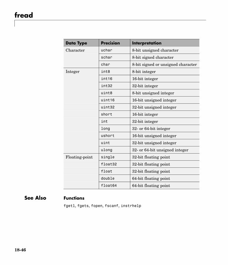
fread
Data Type Precision Interpretation
uchar 8-bit unsigned character
schar 8-bit signed character
Character
char 8-bit signed or unsigned character
int8 8-bit integer
int16 16-bit integer
int32 32-bit integer
uint8 8-bit unsigned integer
uint16 16-bit unsigned integer
uint32 32-bit unsigned integer
short 16-bit integer
int 32-bit integer
long 32- or 64-bit integer
ushort 16-bit unsigned integer
uint 32-bit unsigned integer
Integer
ulong 32- or 64-bit unsigned integer
single 32-bit floating point
float32 32-bit floating point
float 32-bit floating point
double 64-bit floating point
Floating-point
float64 64-bit floating point
See Also Functions
fgetl, fgets, fopen, fscanf, instrhelp
18-46

fread
Properties
BytesAvailable, InputBufferSize, Status, ValuesReceived
18-47

fscanf
Purpose Read data from instrument, and format as text
Syntax A = fscanf(obj)A = fscanf(obj,'format')A = fscanf(obj,'format',size)[A,count] = fscanf(...)[A,count,msg] = fscanf(...)[A,count,msg,datagramaddress] = fscanf(obj,...)[A,count,msg,datagramaddress,datagramport] = fscanf(obj,...)
Arguments obj An interface object.
'format' C language conversion specification.
size The number of values to read.
A Data read from the instrument and formattedas text.
count The number of values read.
msg A message indicating if the read operation wasunsuccessful.
datagramaddress The address of the datagram sender.
datagramport The port of the datagram sender.
Description A = fscanf(obj) reads data from the instrument connected to obj,and returns it to A. The data is converted to text using the %c format.
A = fscanf(obj,'format') reads data and converts it according toformat.
format is a C language conversion specification. Conversionspecifications involve the % character and the conversion characters d,i, o, u, x, X, f, e, E, g, G, c, and s. Refer to the sscanf file I/O formatspecifications or a C manual for more information.
18-48

fscanf
A = fscanf(obj,'format',size) reads the number of values specifiedby size. Valid options for size are
n Read at most n values into a column vector.
[m,n] Read at most m–by–n values filling an m–by–n matrixin column order.
size cannot be inf, and an error is returned if the specified number ofvalues cannot be stored in the input buffer. If size is not of the form[m,n], and a character conversion is specified, then A is returned as arow vector. You specify the size, in bytes, of the input buffer with theInputBufferSize property. An ASCII value is one byte.
If obj is a UDP object and DatagramTerminateMode is off, the sizevalue is honored. If size is less than the length of the datagram,only size values are read. If size is greater than the length of thedatagram, a warning is issued stating that a complete datagram wasread before size values was reached.
[A,count] = fscanf(...) returns the number of values read to count.
[A,count,msg] = fscanf(...) returns a warning message to msg ifthe read operation did not complete successfully.
[A,count,msg,datagramaddress] = fscanf(obj,...) returns thedatagram address to datagramaddress if obj is a UDP object. If morethan one datagram is read, datagramaddress is ’ ’.
[A,count,msg,datagramaddress,datagramport] =fscanf(obj,...) returns the datagram port to datagramport if obj isa UDP object. If more than one datagram is read, datagramport is [ ].
Remarks Before you can read data from the instrument, it must be connected toobj with the fopen function. A connected interface object has a Statusproperty value of open. An error is returned if you attempt to perform aread operation while obj is not connected to the instrument.
If msg is not included as an output argument and the read operation wasnot successful, then a warning message is returned to the command line.
18-49

fscanf
The ValuesReceived property value is increased by the number ofvalues read — including the terminator — each time fscanf is issued.
Rules for Completing a Read Operation with fscanf
A read operation with fscanf blocks access to the MATLAB commandline until
• The terminator is read. For serial port, TCPIP, UDP, and VISA-serialobjects, the terminator is given by the Terminator property.If Terminator is empty, fscanf will complete execution andreturn control when another criterion is met. For UDP objects,DatagramTerminateMode must be off.
For all other interface objects, the terminator is given by theEOSCharCode property.
• The time specified by the Timeout property passes.
• The number of values specified by size is read. For UDP objects,DatagramTerminateMode must be off.
• A datagram is received (for UDP objects only whenDatagramTerminateMode is on).
• The input buffer is filled.
• The EOI line is asserted (GPIB and VXI instruments only).
More About the GPIB and VXI Terminator
The EOSCharCode property value is recognized only when the EOSModeproperty is configured to read or read&write. For example, if EOSModeis configured to read and EOSCharCode is configured to LF, then oneof the ways that the read operation terminates is when the line feedcharacter is received.
If EOSMode is none or write, then there is no terminator defined for readoperations. In this case, fscanf will complete execution and returncontrol to the command when another criterion, such as a timeout, ismet.
18-50

fscanf
Examples Create the serial port object s and connect s to a Tektronix TDS 210oscilloscope, which is displaying a sine wave.
s = serial('COM1');fopen(s)
Use the fprintf function to configure the scope to measure thepeak-to-peak voltage of the sine wave, return the measurement type,and return the peak-to-peak voltage.
fprintf(s,'MEASUREMENT:IMMED:TYPE PK2PK')fprintf(s,'MEASUREMENT:IMMED:TYPE?')fprintf(s,'MEASUREMENT:IMMED:VAL?')
Because the default value for the ReadAsyncMode property iscontinuous, data associated with the two query commands isautomatically returned to the input buffer.
s.BytesAvailableans =
13
Use fscanf to read the measurement type. The operation will completewhen the first terminator is read.
meas = fscanf(s)meas =PK2PK
Use fscanf to read the peak-to-peak voltage as a floating-point number,and exclude the terminator.
pk2pk = fscanf(s,'%e',6)pk2pk =
2.0200
18-51

fscanf
Disconnect s from the scope, and remove s from memory and theworkspace.
fclose(s)delete(s)clear s
See Also Functions
fgetl, fgets, fopen, fread, instrhelp, scanstr, sscanf
Properties
BytesAvailable, BytesAvailableFcn, EOSCharCode, EOSMode,InputBufferSize, Status, Terminator, Timeout, TransferStatus
18-52

fwrite
Purpose Write binary data to instrument
Syntax fwrite(obj,A)fwrite(obj,A,'precision')fwrite(obj,A,'mode')fwrite(obj,A,'precision','mode')
Arguments obj An interface object.
A The binary data written to the instrument.
'precision' The number of bits written for each value, and theinterpretation of the bits as character, integer, orfloating-point values.
'mode' Specifies whether data is written synchronously orasynchronously.
Description fwrite(obj,A) writes the binary data A to the instrument connectedto obj.
fwrite(obj,A,'precision') writes binary data with precisionspecified by precision.
precision controls the number of bits written for each value and theinterpretation of those bits as integer, floating-point, or charactervalues. If precision is not specified, uchar (an 8-bit unsignedcharacter) is used. The support values for precision are listed in“Supported Precisions” on page 18-45.
fwrite(obj,A,'mode') writes binary data with command line accessspecified by mode. If mode is sync, A is written synchronously and thecommand line is blocked. If mode is async, A is written asynchronouslyand the command line is not blocked. If mode is not specified, the writeoperation is synchronous.
fwrite(obj,A,'precision','mode') writes binary data withprecision specified by precision and command-line access specifiedby mode.
18-53

fwrite
Remarks Before you can write data to the instrument, it must be connected toobj with the fopen function. A connected interface object has a Statusproperty value of open. An error is returned if you attempt to perform awrite operation while obj is not connected to the instrument.
The ValuesSent property value is increased by the number of valueswritten each time fwrite is issued.
An error occurs if the output buffer cannot hold all the data tobe written. You can specify the size of the output buffer with theOutputBufferSize property.
fwrite will return an error message if you set the flowcontrolproperty to hardware and a hardware connection is not detected.
Synchronous Versus Asynchronous Write Operations
By default, data is written to the instrument synchronously and thecommand line is blocked until the operation completes. You can performan asynchronous write by configuring the mode input argument to beasync. For asynchronous writes,
• The BytesToOutput property value is continuously updated to reflectthe number of bytes in the output buffer.
• The M-file callback function specified for the OutputEmptyFcnproperty is executed when the output buffer is empty.
You can determine whether an asynchronous write operation is inprogress with the TransferStatus property.
Synchronous and asynchronous write operations are discussed in moredetail in “Synchronous Versus Asynchronous Write Operations” on page3-17.
Rules for Completing a Write Operation with fwrite
A binary write operation using fwrite completes when
• The specified data is written.
• The time specified by the Timeout property passes.
18-54

fwrite
Note The Terminator and EOSCharCode properties are not used withbinary write operations.
Supported Precisions
The supported values for precision are listed below.
Data Type Precision Interpretation
uchar 8-bit unsigned character
schar 8-bit signed character
Character
char 8-bit signed or unsignedcharacter
int8 8-bit integer
int16 16-bit integer
int32 32-bit integer
uint8 8-bit unsigned integer
uint16 16-bit unsigned integer
uint32 32-bit unsigned integer
short 16-bit integer
int 32-bit integer
long 32- or 64-bit integer
ushort 16-bit unsigned integer
uint 32-bit unsigned integer
Integer
ulong 32- or 64-bit unsignedinteger
18-55

fwrite
Data Type Precision Interpretation
single 32-bit floating point
float32 32-bit floating point
float 32-bit floating point
double 64-bit floating point
Floating-point
float64 64-bit floating point
See Also Functions
fopen, fprintf, instrhelp
Properties
OutputBufferSize, OutputEmptyFcn, Status, Timeout,TransferStatus, ValuesSent
18-56

get
Purpose Instrument object properties
Syntax get(obj)out = get(obj)out = get(obj,'PropertyName')
Arguments obj An instrument object or an array of instrumentobjects.
'PropertyName' A property name or a cell array of propertynames.
out A single property value, a structure of propertyvalues, or a cell array of property values.
Description get(obj) returns all property names and their current values to thecommand line for obj. The properties are divided into two sections.The base properties are listed first and the object-specific propertiesare listed second.
out = get(obj) returns the structure out where each field name is thename of a property of obj, and each field contains the value of thatproperty.
out = get(obj,'PropertyName') returns the value out of the propertyspecified by PropertyName for obj. If PropertyName is replaced by a1-by-n or n-by-1 cell array of strings containing property names, thenget returns a 1-by-n cell array of values to out. If obj is an array ofinstrument objects, then out will be an m-by-n cell array of propertyvalues where m is equal to the length of obj and n is equal to thenumber of properties specified.
Remarks When specifying a property name, you can do so without regard to case,and you can make use of property name completion. For example, if g isa GPIB object, then these commands are all valid.
out = get(g,'EOSMode');
18-57

get
out = get(g,'eosmode');out = get(g,'EOSM');
Examples This example illustrates some of the ways you can use get to returnproperty values for the GPIB object g.
g = gpib('ni',0,1);out1 = get(g);out2 = get(g,{'PrimaryAddress','EOSCharCode'});get(g,'EOIMode')ans =on
See Also Functions
instrhelp, propinfo, set
18-58

geterror
Purpose Check and return error message from instrument
Syntax msg = geterror(obj)
Arguments obj A device object.
msg The error message returned from the instrument.
Description msg = geterror(obj) checks the instrument associated with thedevice object specified by obj for an error message. If an error messageexists, it is returned to msg. The interpretation of msg will vary basedon the instrument.
18-59

gpib
Purpose Create GPIB object
Syntax obj = gpib('vendor', boardindex, primaryaddress)obj =gpib('vendor',boardindex,primaryaddress,'PropertyName',
PropertyValue,...)
Arguments 'vendor' The vendor name.
boardindex The GPIB board index.
primaryaddress The instrument primary address.
'PropertyName' A GPIB property name.
'PropertyValue' A property value supported by PropertyName.
obj The GPIB object.
Description obj = gpib('vendor', boardindex, primaryaddress) creates theGPIB object obj associated with the board specified by boardindex, andthe instrument specified by primaryaddress. The GPIB hardware issupplied by vendor. Supported vendors are given below.
Vendor Description
advantech Advantech Company hardware
agilent Agilent Technologies hardware
cec Capital Equipment Corporation hardware
contec CONTEC hardware
ics ICS Electronics hardware
iotech IOTech hardware
keithley Keithley Instruments hardware
18-60

gpib
Vendor Description
mcc Measurement Computing Corporationhardware
ni National Instruments hardware
obj =gpib('vendor',boardindex,primaryaddress,'PropertyName',PropertyValue,...) creates the GPIB object with the specifiedproperty names and property values. If an invalid property name orproperty value is specified, an error is returned and obj is not created.
Remarks At any time, you can use the instrhelp function to view a completelisting of properties and functions associated with GPIB objects.
instrhelp gpib
When you create a GPIB object, these property value are automaticallyconfigured:
• Type is given by gpib.
• Name is given by concatenating GPIB with the board index and theprimary address specified in the gpib function. If the secondaryaddress is specified, then this value is also used in Name.
• BoardIndex and PrimaryAddress are given by the values supplied tothe gpib function.
Note You do not use the GPIB board primary address in the GPIBobject constructor syntax. You use the board index, and the instrumentaddress.
You can specify the property names and property values using anyformat supported by the set function. For example, you can useproperty name/property value cell array pairs. Additionally, you can
18-61

gpib
specify property names without regard to case, and you can make use ofproperty name completion. For example, these commands are all valid:
g = gpib('ni',0,1,'SecondaryAddress',96);g = gpib('ni',0,1,'secondaryaddress',96);g = gpib('ni',0,1,'SECOND',96);
Before you can communicate with the instrument, it must be connectedto obj with the fopen function. A connected GPIB object has a Statusproperty value of open. An error is returned if you attempt to perform aread or write operation while obj is not connected to the instrument.
You cannot connect multiple GPIB objects to the same instrument. AGPIB instrument is uniquely identified by its board index, primaryaddress, and secondary address.
Examples This example creates the GPIB object g1 associated with a NationalInstruments board at index 0 with primary address 1, and then connectsg1 to the instrument.
g1 = gpib('ni',0,1);fopen(g1)
The Type, Name, BoardIndex, and PrimaryAddress properties areautomatically configured.
get(g1, {'Type','Name','BoardIndex','PrimaryAddress'})ans =
'gpib' 'GPIB0-1' [0] [1]
To specify the secondary address during object creation,
g2 = gpib('ni',0,1,'SecondaryAddress',96);
See Also Functions
fopen, instrhelp, instrhwinfo
18-62

gpib
Properties
BoardIndex, Name, PrimaryAddress, SecondaryAddress, Status, Type
18-63

icdevice
Purpose Create device object
Syntax obj = icdevice('driver', hwobj)obj = icdevice('driver', 'RsrcName')obj = icdevice('driver')obj = icdevice('driver', hwobj, 'P1', V1, 'P2', V2,...)obj = icdevice('driver', 'RsrcName','P1', V1, 'P2', V2,...)obj = icdevice('driver','P1', V1, 'P2', V2,...)
Arguments driver A MATLAB instrument driver.
hwobj An interface object.
RsrcName VISA resource name.
'P1','P2',...
Device-specific property names.
V1, V2,... Property values supported by corresponding P1,P2,....
obj A device object.
Description obj = icdevice('driver', hwobj) creates the device object obj. Theinstrument-specific information is defined in the MATLAB interfaceinstrument driver, driver. Communication to the instrument is donethrough the interface object, hwobj. The interface object can be a serialport, GPIB, VISA, TCPIP, or UDP object. If driver does not exist or ifhwobj is invalid, the device object is not created.
Device objects may also be used with VXIplug&play and InterchangeableVirtual Instrument (IVI) drivers. To use these drivers, you mustfirst have a MATLAB instrument driver wrapper for the underlyingVXIplug&play or IVI driver. If the MATLAB instrument driver wrapperdoes not already exist, it may be created using makemid or midedit.Note that makemid or midedit only needs to be used once to create theMATLAB instrument driver wrapper.
18-64

icdevice
obj = icdevice('driver', 'RsrcName') creates a device object obj,using the MATLAB instrument driver, driver. The specified drivermust be a MATLAB VXIplug&play instrument driver or MATLAB IVIinstrument driver. Communication to the instrument is done throughthe resource specified by rsrcname. For example, all VXIplug&play,and many IVI drivers require VISA resource names for rsrcname.
obj = icdevice('driver') constructs a device object obj, using theMATLAB instrument driver, driver. The specified driver must be aMATLAB IVI instrument driver, and the underlying IVI driver must bereferenced using a logical name.
obj = icdevice('driver', hwobj, 'P1', V1, 'P2', V2,...), obj= icdevice('driver', 'RsrcName','P1', V1, 'P2', V2,...), andobj = icdevice('driver','P1', V1, 'P2', V2,...), construct adevice object, obj, with the specified property values. If an invalidproperty name or property value is specified, the object will not becreated.
Note that the parameter-value pairs can be in any format supportedby the set function: parameter-value string pairs, structures, andparameter-value cell array pairs.
Additionally, you can specify property names without regard to case,and you can make use of property name completion. For example, thesecommands are all valid and equivalent:
d = icdevice('tektronix_tds210',g,'ObjectVisibility','on');d = icdevice('tektronix_tds210',g,'objectvisibility','on');d = icdevice('tektronix_tds210',g,'ObjectVis','on');
Remarks At any time, you can use the instrhelp function to view a completelisting of properties and functions associated with device objects.
instrhelp icdevice
When you create a device object, these property values are automaticallyconfigured:
18-65

icdevice
• Interface specifies the interface used to communicate with theinstrument. For device objects created using interface objects, it isthat interface object. For VXIplug&play and IVI-C, this is the sessionhandle to the driver session. For IVI-COM and MATLAB instrumentdrivers, this is the handle to the driver’s default COM interface.
• LogicalName is an IVI logical name. For non-IVI drivers, it is empty.
• Name is given by concatenating the instrument type with the nameof the instrument driver.
• RsrcName is the full VISA resource name for VXIplug&play and IVIdrivers. For MATLAB interface drivers, RsrcName is an empty string.
• Type is the instrument type, if known (for example, scope ormultimeter).
To communicate with the instrument, the device object must beconnected to the instrument with the connect function. When thedevice object is constructed, the object’s Status property is closed.Once the device object is connected to the instrument with the connectfunction, the Status property is configured to open.
Examples The first example creates a device object for a Tektronix TDS 210oscilloscope that is connected to a Keithley GPIB board, using aMATLAB interface object and MATLAB interface instrument driver.
g = gpib('keithley',0,2);d = icdevice('tektronix_tds210',g);
Connect to the instrument.
connect(d);
List the oscilloscope settings that can be configured.
props = set(d);
Get the current configuration of the oscilloscope.
18-66

icdevice
values = get(d);
Disconnect from the instrument and clean up.
disconnect(d);delete([d g]);
The second example creates a device object for a Tektronix TDS 210oscilloscope using a MATLAB VXIplug&play instrument driver.
This example assumes that the 'tktds5k' VXIplug&play driver isinstalled on your system.
This first step is necessary only if a MATLAB VXIplug&play instrumentdriver for the tktds5k does not exist on your system.
makemid('tktds5k', 'Tktds5kMATLABDriver');
Construct a device object that uses the VXIplug&play driver. Theinstrument is assumed to be located at GPIB primary address 2.
d = icdevice('Tktds5kMATLABDriver', 'GPIB0::2::INSTR');
Connect to the instrument.
connect(d);
List the oscilloscope settings that can be configured.
props = set(d);
Get the current configuration of the oscilloscope.
values = get(d);
Disconnect from the instrument and clean up.
disconnect(d);delete(d);
18-67

icdevice
See Also Functions
icdevice/connect, icdevice/disconnect, instrhelp
Properties
Status
18-68

inspect
Purpose Open Property Inspector
Syntax inspect(obj)
Arguments obj An instrument object or an array of instrument objects.
Description inspect(obj) opens the Property Inspector and allows you to inspectand set properties for instrument object obj.
Remarks You can also open the Property Inspector via the Workspace browserby right-clicking an instrument object and selecting Call PropertyInspector from the context menu, or by double-clicking the object.
Below is a Property Inspector for a device object that communicateswith a Tektronix TDS 210 oscilloscope.
18-69

inspect
18-70

instrcallback
Purpose Display event information when event occurs
Syntax instrcallback(obj, event)
Arguments obj An instrument object.
event The event that caused the callback to execute.
Description instrcallback(obj, event) displays a message that contains theevent type, the time the event occurred, and the name of the instrumentobject that caused the event to occur.
For error events, the error message is also displayed. For pin statusevents, the pin that changed value and its value are also displayed. Fortrigger events, the trigger line is also displayed. For datagram receivedevents, the number of bytes received and the datagram address andport are also displayed.
Remarks You should use instrcallback as a template from which you createcallback functions that suit your specific application needs.
Examples The following example creates the serial port objects s, and configuress to execute instrcallback when an output-empty event occurs. Theevent occurs after the *IDN? command is written to the instrument.
s = serial('COM1');set(s,'OutputEmptyFcn',@instrcallback)fopen(s)fprintf(s,'*IDN?','async')
The resulting display from instrcallback is shown below.
OutputEmpty event occurred at 08:37:49 for the object: Serial-COM1
18-71

instrcallback
Read the identification information from the input buffer and end theserial port session.
idn = fscanf(s);fclose(s)delete(s)clear s
18-72

instrfind
Purpose Read instrument objects from memory to MATLAB workspace
Syntax out = instrfindout = instrfind('PropertyName',PropertyValue,...)out = instrfind(S)out = instrfind(obj,'PropertyName',PropertyValue,...)
Arguments 'PropertyName' A property name for obj.
PropertyValue A property value supported by PropertyName.
S A structure of property names and property values.
obj An instrument object, or an array of instrumentobjects.
out An array of instrument objects.
Description out = instrfind returns all valid instrument objects as an array toout.
out = instrfind('PropertyName',PropertyValue,...) returns anarray of instrument objects whose property names and property valuesmatch those specified.
out = instrfind(S) returns an array of instrument objects whoseproperty names and property values match those defined in thestructure S. The field names of S are the property names, while the fieldvalues are the associated property values.
out = instrfind(obj,'PropertyName',PropertyValue,...)restricts the search for matching property name/property value pairs tothe instrument objects listed in obj.
Remarks instrfind will not return an instrument object if its ObjectVisibilityproperty is configured to off.
You must specify property values using the same format as the getfunction returns. For example, if get returns the Name property value as
18-73

instrfind
MyObject, instrfind will not find an object with a Name property valueof myobject. However, this is not the case for properties that have afinite set of string values. For example, instrfind will find an objectwith a Parity property value of Even or even. You can use the propinfofunction to determine if a property has a finite set of string values.
You can use property name/property value string pairs, structures, andcell array pairs in the same call to instrfind.
Examples Suppose you create the following two GPIB objects.
g1 = gpib('ni',0,1);g2 = gpib('ni',0,2);g2.EOSCharCode = 'CR';fopen([g1 g2])
You can use instrfind to return instrument objects based on propertyvalues.
out1 = instrfind('Type','gpib');out2 = instrfind({'Type','EOSCharCode'},{'gpib','CR'});
You can also use instrfind to return cleared instrument objects tothe MATLAB workspace.
clear g1 g2newobjs = instrfind
Instrument Object ArrayIndex: Type: Status: Name:1 gpib open GPIB0-12 gpib open GPIB0-2
Assign the instrument objects their original names.
g1 = newobjs(1);g2 = newobjs(2);
18-74

instrfind
Close both g1 and g2.
fclose(newobjs)
See Also Functions
clear, get, instrfindall, propinfo
Properties
ObjectVisibility
18-75

instrfindall
Purpose Find visible and hidden instrument objects
Syntax out = instrfindallout = instrfindall('P1',V1,...)out = instrfindall(s)out = instrfindall(objs,'P1',V1,...)
Arguments 'P1' Name of an instrument object property or device groupobject property
V1 Value allowed for corresponding P1.
s A structure of property names and property values.
objs An array of instrument objects or device group objects.
out An array of returned instrument objects or device groupobjects.
Description out = instrfindall finds all instrument objects and device groupobjects, regardless of the value of the objects’ ObjectVisibilityproperty. The object or objects are returned to out.
out = instrfindall('P1',V1,...) returns an array, out, ofinstrument objects and device group objects whose property names andcorresponding property values match those specified as arguments.
out = instrfindall(s) returns an array, out, of instrument objectswhose property names and corresponding property values match thosespecified in the structure s, where the field names correspond toproperty names and the field values correspond to the current valueof the respective property.
out = instrfindall(objs,'P1',V1,...) restricts the search forobjects with matching property name/value pairs to the instrumentobjects and device group objects listed in objs.
18-76

instrfindall
Note that you can use string property name/property value pairs,structures, and cell array property name/property value pairs in thesame call to instrfindall.
Remarks instrfindall differs from instrfind in that it finds objects whoseObjectVisibility property is set to off.
Property values are case sensitive. You must specify propertyvalues using the same format as that returned by the get function.For example, if get returns the Name property value as MyObject,instrfindall will not find an object with a Name property value ofmyobject. However, this is not the case for properties that have a finiteset of string values.
For example, instrfindall will find an object with a Parity propertyvalue of Even or even. You can use the propinfo function to determineif a property has a finite set of string values.
Examples Suppose you create the following instrument objects.
s1 = serial('COM1');s2 = serial('COM2');g1 = gpib('keithley',0,2);set(g1,'ObjectVisibility','off')
Because object g1 has its ObjectVisibility set to off, it is not visible tocommands like instrfind:
instrfind
Instrument Object ArrayIndex: Type: Status: Name:1 serial closed Serial-COM12 serial closed Serial-COM2
18-77

instrfindall
However, instrfindall finds all objects regardless of the value ofObjectVisibility:
instrfindall
Instrument Object ArrayIndex: Type: Status: Name:1 serial closed Serial-COM12 serial closed Serial-COM23 gpib closed GPIB0-2
The following statements use instrfindall to return objects withspecific property settings, which are passed as cell arrays:
props = {'PrimaryAddress','SecondaryAddress};vals = {2,0};obj = instrfindall(props,vals);
You can use instrfindall as an argument when you want to apply thecommand to all objects, visible and invisible. For example, the followingstatement makes all objects visible:
set(instrfindall,'ObjectVisibility','on')
See Also Functions
instrfind, propinfo
Properties
ObjectVisibility
18-78

instrhelp
Purpose Help for instrument object type, function, or property
Syntax instrhelpinstrhelp('name')out = instrhelp('name')instrhelp(obj)instrhelp(obj,'name')out = instrhelp(obj,'name')
Arguments 'name' A function name, property name, or instrument objecttype.
obj An instrument object.
out The help text.
Description instrhelp returns a complete listing of toolbox functions, with a briefdescription of each.
instrhelp('name') returns help for the function, property, orinstrument object type specified by name.
You can return specific instrument object information by specifyingname in the form object/function or object.property. For example,to return the help for a serial port object’s fprintf function, name wouldbe serial/fprintf. To return the help for a serial port object’s Parityproperty, name would be serial.parity.
out = instrhelp('name') returns the help text to out.
instrhelp(obj) returns a complete listing of functions and propertiesfor obj, with a brief description of each. Help for the constructor isalso returned.
instrhelp(obj,'name') returns help for the function or propertyspecified by name associated with obj.
out = instrhelp(obj,'name') returns the help text to out.
18-79

instrhelp
Remarks When returning property help, the names in the See Also section thatcontain all uppercase letters are function names. The names thatcontain a mixture of upper and lowercase letters are property names.When returning function help, the See Also section contains onlyfunction names.
You can also display help via the Workspace browser by right-clickingan instrument object, and selecting Instrument Help from the contextmenu.
Examples The following commands illustrate some of the ways you can getfunction and property help without creating an instrument object.
instrhelp gpibout = instrhelp('gpib.m');instrhelp setinstrhelp('gpib/set')instrhelp EOSCharCodeinstrhelp('gpib.eoscharcode')
The following commands illustrate some of the ways you can getfunction and property help for an existing instrument object.
g = gpib('ni',0,1);instrhelp(g)instrhelp(g,'EOSMode');out = instrhelp(g,'trigger');
See Also Functions
propinfo
18-80

instrhwinfo
Purpose Information about available hardware
Syntax out = instrhwinfoout = instrhwinfo('interface')out = instrhwinfo('drivertype')out = instrhwinfo('interface','adaptor')out = instrhwinfo('drivertype','drivername')out = instrhwinfo('ivi','LogicalName')out = instrhwinfo('interface','adaptor','type')out = instrhwinfo(obj)out = instrhwinfo(obj,'FieldName')
Arguments 'interface' A supported instrument interface.
’drivertype’ Instrument driver type, may be matlab or vxipnp.
'adaptor' A supported GPIB or VISA adaptor.
'drivername' Name of VXIplug&play or MATLAB instrumentdriver.
'LogicalName' IVI logical name value.
'type' Type of VISA interface.
obj An instrument object or array of instrumentobjects.
'FieldName' A field name or cell array of field names associatedwith obj.
out A structure or array containing hardwareinformation.
Description out = instrhwinfo returns hardware information to the structureout. This information includes the toolbox version, MATLAB version,and supported interfaces.
out = instrhwinfo('interface') returns information related to theinterface specified by interface. interface can be serial, gpib,
18-81

instrhwinfo
tcpip, udp, or visa. For the GPIB and VISA interfaces, the informationincludes the installed adaptors. For the serial port interface, theinformation includes the available ports and the object constructorname. For the TCP/IP and UDP interfaces, the information includes thelocal host address.
out = instrhwinfo('drivertype') returns a structure, out, whichcontains information related to the specified driver type, drivertype.drivertype can be matlab, vxipnp, or ivi. If drivertype is matlab,this information includes the MATLAB instrument drivers found on theMATLAB path. If drivertype is vxipnp, this information includes thefound VXIplug&play drivers. If drivertype is ivi, this informationincludes the available logical names and information on the IVIconfiguration store.
out = instrhwinfo('interface','adaptor') returns informationrelated to the adaptor specified by adaptor, and for the interfacespecified by interface. interface can be gpib or visa. The returnedinformation includes the adaptor version and available hardware. TheGPIB adaptors are advantech, agilent, cec, contec, ics, iotech,keithley, mcc, and ni. The VISA adaptors are agilent, ni, and tek.
out = instrhwinfo('drivertype','drivername') returns astructure, out, which contains information related to the specifieddriver, drivername, for the specified drivertype. drivertype can beset to matlab, or vxipnp. The available drivername values are returnedby out = instrhwinfo('drivertype').
out = instrhwinfo('ivi','LogicalName') returns a structure,out, which contains information related to the specified logical name,LogicalName. The available logical name values are returned byinstrhwinfo('ivi').
out = instrhwinfo('interface','adaptor','type') returns astructure, out, which contains information on the specified type, type.interface can only be visa. adaptor can be agilent, ni, or tek. typecan be gpib, vxi, gpib-vxi, serial, or rsib.
out = instrhwinfo(obj) returns information on the adaptor andvendor-supplied DLL associated with the VISA or GPIB object obj. If
18-82

instrhwinfo
obj is a serial port, TCPIP, or UDP object, then JAR file information isreturned. If obj is an array of instrument objects, then out is a 1-by-ncell array of structures where n is the length of obj.
out = instrhwinfo(obj,'FieldName') returns hardware informationfor the field name specified by FieldName. FieldName can be a singlestring or a cell array of strings. out is an m-by-n cell array where m isthe length of obj and n is the length of FieldName. You can return thesupported values for FieldName using the instrhwinfo(obj) syntax.
Remarks You can also display hardware information via the Workspacebrowser by right-clicking an instrument object, and selecting DisplayHardware Info from the context menu.
Examples The following commands illustrate some of the ways you can gethardware-related information without creating an instrument object.
out1 = instrhwinfo;out2 = instrhwinfo('serial');out3 = instrhwinfo('gpib','ni');out4 = instrhwinfo('visa','agilent');
The following commands illustrate some of the ways you can gethardware-related information for an existing instrument object.
vs = visa('agilent','ASRL1::INSTR');out5 = instrhwinfo(vs)out5 =
AdaptorDllName: [1x67 char]AdaptorDllVersion: 'Version 1.2 (R13)'
AdaptorName: 'AGILENT'VendorDriverDescription: 'Agilent Technologies VISA Driver'
VendorDriverVersion: '1.1000'
vsdll = instrhwinfo(vs,'AdaptorDllName')vsdll = D:\V6\toolbox\instrument\instrumentadaptors\win32\mwagilentvisa.dll
18-83

instrid
Purpose Define and retrieve commands that identify instruments
Syntax instridinstrid('cmd')out = instrid(...)
Arguments cmd The instrument identification command.
out The list of commands used to locate and identifyinstruments.
Description instrid returns the currently defined instrument identificationcommands.
instrid('cmd') defines the instruments identification commands to bethe string cmd. Note that you can also specify a cell array of commands.
out = instrid(...) returns the instrument identification commandsto out.
Remarks The Instrument Control Toolbox instrhwinfo and tmtool functions usethe instrument identification commands as defined by instrid whenlocating and identifying instruments.
By default, Instrument Control Toolbox uses the command *IDN?, whichidentifies most instruments. However, some instruments respond todifferent identification commands such as *ID? or *IDEN?.
If instrhwinfo or tmtool does not identify a known instrument, useinstrid to specify the identification commands the instrument willrespond to. If instrid returns no commands, an instrument cannotbe found.
Examples Set the identification command to *ID?.
instrid('*ID?')
18-84

instrid
Specify three new identification commands using a cell array.
instrid({'*IDN?','*ID?','IDEN?'})
Assign a list of current identification commands to an output variable.
id_commands = instrid;
See Also instrhwinfo, tmtool
18-85

instrnotify
Purpose Define notification for instrument events
Syntax instrnotify('Type', callback)instrnotify({'P1', 'P2', ...}, 'Type', callback)instrnotify(obj, 'Type', callback)instrnotify(obj, {'P1', 'P2', ...}, 'Type', callback)instrnotify('Type', callback, '-remove')instrnotify(obj, 'Type', callback, '-remove')
Arguments 'Type' The type of event: ObjectCreated, ObjectDeleted,or PropertyChangedPostSet
callback Function handle, string, or cell array to evaluate.
'P1', P2',...
Any number of object property names.
obj Instrument object or device group object.
'-remove' Argument to remove specified callback.
Description instrnotify('Type', callback) evaluates the MATLAB expression,callback, in the MATLAB workspace when an event of type Typeis generated. Type can be ObjectCreated, ObjectDeleted, orPropertyChangedPostSet.
If Type is ObjectCreated, callback is evaluated each time aninstrument object or a device group object is created. If Type isObjectDeleted, callback is evaluated each time an instrument objector a device group object is deleted. If Type is PropertyChangedPostSet,callback is evaluated each time an instrument object or device groupobject property is configured with set.
callback can be
• A function handle
• A string to be evaluated
18-86

instrnotify
• A cell array containing the function to evaluate in the first cell(function handle or name of function) and extra arguments to pass tothe function in subsequent cells
The callback function is invoked with
function(obj, event, [arg1, arg2,...])
where obj is the instrument object or device group object generatingthe event. event is a structure containing information on the eventgenerated. If Type is ObjectCreated or ObjectDeleted, event containsthe type of event. If Type is PropertyChangedPostSet, event containsthe type of event, the property being configured, and the new propertyvalue.
instrnotify({'P1', 'P2', ...}, 'Type', callback) evaluatesthe MATLAB expression, callback, in the MATLAB workspace whenany of the specified properties, P1, P2, ... are configured. Type can beonly PropertyChangedPostSet.
instrnotify(obj, 'Type', callback) evaluates the MATLABexpression, callback, in the MATLAB workspace when an event of typeType for object obj, is generated. obj can be an array of instrumentobjects or device group objects.
instrnotify(obj, {'P1', 'P2', ...}, 'Type', callback)evaluates the MATLAB expression, callback, in the MATLABworkspace when any of the specified properties, P1, P2, are configuredon object obj.
instrnotify('Type', callback, '-remove') removes the specifiedcallback of type Type.
instrnotify(obj, 'Type', callback, '-remove') removes thespecified callback of type Type for object obj.
Remarks PropertyChangedPostSet events are generated only when theproperty is configured to a different value than what the property iscurrently configured to. For example, if a GPIB object’s Tag property isconfigured to 'myobject', a PropertyChangedPostSet event will not
18-87

instrnotify
be generated if the object’s Tag property is currently set to 'myobject'.A PropertyChangedPostSet event will be generated if the object’s Tagproperty is set to 'myGPIBObject'.
If obj is specified and the callback Type is ObjectCreated, the callbackwill not be generated because obj has already been created.
If Type is ObjectDeleted, the invalid object obj is not passed as thefirst input argument to the callback function. Instead, an emptymatrix is passed as the first input argument.
Examples instrnotify('PropertyChangedPostSet', @instrcallback);g = gpib('keithley', 0, 5);set(g, 'Name', 'mygpib');fopen(g);fclose(g);instrnotify('PropertyChangedPostSet',@instrcallback,'-remove');
18-88

instrreset
Purpose Disconnect and delete all instrument objects
Syntax instrreset
Description instrreset disconnects and deletes all instrument objects.
Remarks If data is being written or read asynchronously, the asynchronousoperation is stopped.
instrreset is equivalent to issuing the stopasync (if needed), fclose,and delete functions for all instrument objects.
When you delete an instrument object, it becomes invalid. Because youcannot connect an invalid object to the instrument, you should removeit from the workspace with the clear command.
See Also Functions
clear, delete, fclose, isvalid, stopasync
18-89

invoke
Purpose Execute driver-specific function on device object
Syntax out = invoke(obj,'name')out = invoke(obj,'name',arg1,arg2,...)
Arguments obj A device object.
name The function to execute.
arg1,arg2,... Arguments passed to name.
out The function output.
Description out = invoke(obj,'name') executes the function specified by name onthe device object specified by obj. The function’s output is returnedto out.
out = invoke(obj,'name',arg1,arg2,...) passes the argumentsarg1,arg2,... to the function specified by name.
Remarks To list the driver-specific functions supported by obj, type
methods(obj)
To display help for a specific function, type
instrhelp(obj,'name')
Examples Create a device object for a Tektronix TDS 210 oscilloscope that isconnected to a National Instruments GPIB board.
g = gpib('ni',0,2);d = icdevice('tektronix_tds210',g);
Perform a self-calibration for the oscilloscope by invoking the calibratefunction.
out = invoke(d,'calibrate')
18-90

invoke
out ='0'
0 indicates that the self-calibration completed without any errors.
See Also Functions
instrhelp, methods
Properties
Status
18-91

isvalid
Purpose Determine whether instrument objects are valid
Syntax out = isvalid(obj)
Arguments obj An instrument object or array of instrument objects.
out A logical array.
Description out = isvalid(obj) returns the logical array out, which contains a 0where the elements of obj are invalid instrument objects and a 1 wherethe elements of obj are valid instrument objects.
Remarks obj becomes invalid after it is removed from memory with thedelete function. Because you cannot connect an invalid object to theinstrument, you should remove it from the workspace with the clearcommand.
Examples Suppose you create the following two GPIB objects:
g1 = gpib('ni',0,1);g2 = gpib('ni',0,2);
g2 becomes invalid after it is deleted.
delete(g2)
isvalid verifies that g1 is valid and g2 is invalid.
garray = [g1 g2];isvalid(garray)ans =
1 0
See Also Functions
clear, delete
18-92

iviconfigurationstore
Purpose Create IVI configuration store object
Syntax obj = iviconfigurationstoreobj = iviconfigurationstore('file')
Arguments obj IVI configuration store object
'file'Configuration store data file
Description obj = iviconfigurationstore creates an IVI configuration storeobject and establishes a connection to the IVI Configuration Server. Thedata in the master configuration store is used.
obj = iviconfigurationstore('file') creates an IVI configurationstore object and establishes a connection to the IVI ConfigurationServer. The data in the configuration store, file, is used. If filecannot be found or is not a valid configuration store, an error occurs.
See Also Functions
iviconfigurationstore/add, iviconfigurationstore/commit,iviconfigurationstore/remove, iviconfigurationstore/update
18-93

length
Purpose Length of instrument object array
Syntax length(obj)
Arguments obj An instrument object or an array of instrument objects.
Description length(obj) returns the length of obj. It is equivalent to the commandmax(size(obj)).
See Also Functions
instrhelp, size
18-94
load
Purpose Load instrument objects and variables into MATLAB workspace
Syntax load filenameload filename obj1 obj2 ...out = load('filename','obj1','obj2',...)
Arguments filename The MAT-file name.
obj1 obj2 ... Instrument objects or arrays of instrumentobjects.
out A structure containing the specified instrumentobjects.
Description load filename returns all variables from the MAT-file specified byfilename into the MATLAB workspace.
load filename obj1 obj2 ... returns the instrument objectsspecified by obj1 obj2... from the MAT-file filename into theMATLAB workspace.
out = load('filename','obj1','obj2',...) returns the specifiedinstrument objects from the MAT-file filename as a structure to outinstead of directly loading them into the workspace. The field names inout match the names of the loaded instrument objects.
Remarks Values for read-only properties are restored to their default values uponloading. For example, the Status property is restored to closed. Todetermine if a property is read-only, examine its reference pages oruse the propinfo function.
Examples Suppose you create the GPIB objects g1 and g2, configure a fewproperties for g1, and connect both objects to their associatedinstruments.
g1 = gpib('ni',0,1);g2 = gpib('ni',0,2);
18-95

load
set(g1,'EOSMode','read','EOSCharCode','CR')fopen([g1 g2])
The read-only Status property is automatically configured to open.
get([g1 g2],'Status')ans =
'open''open'
Save g1 and g2 to the file MyObject.mat, and then load the objects intothe MATLAB workspace.
save MyObject g1 g2load MyObject g1 g2
Values for read-only properties are restored to their default values uponloading, while all other property values are honored.
get([g1 g2],{'EOSMode','EOSCharCode','Status'})ans =
'read' 'CR' 'closed''none' 'LF' 'closed'
See Also Functions
instrhelp, propinfo, save
18-96

makemid
Purpose Convert driver to MATLAB instrument driver format
Syntax makemid('driver')makemid('driver', 'filename')makemid('driver', 'type')makemid('driver', 'filename', 'type')makemid('driver', 'type', 'interface')makemid('driver', 'filename', 'type', 'interface')
Arguments 'driver' Name of driver being converted.
'filename' Name of file that the converted driver is saved to.You may specify a full pathname. If an extensionis not specified, the .mdd extension is used.
'type' The type of driver the function looks for. Bydefault, the function searches among all types.
'interface' The IVI-COM interface to be used.
Description makemid('driver') searches through known driver types for driverand creates a MATLAB instrument driver representation of the driver.Known driver types include VXIplug&play, IVI-C, and IVI-COM.For driver you can use a Module (for IVI-C), a ProgramID (forIVI-COM), a LogicalName (for either IVI-C or IVI-COM), or the originalVXIplug&play instrument driver name. The MATLAB instrumentdriver will be saved in the current working directory as driver.mdd
The MATLAB instrument driver can then be modified using midedit tocustomize the driver behavior, and may be used to instantiate a deviceobject using icdevice.
makemid('driver', 'filename') creates and saves the MATLABinstrument driver using the name and path specified by filename.
makemid('driver', 'type') and makemid('driver', 'filename','type') override the default search order and look only for driverswhose type is type. Valid types are vxiplug&play, ivi-c, and ivi-com.
18-97

makemid
makemid('driver', 'type', 'interface') and makemid('driver','filename', 'type', 'interface') specify the IVI-COM driverinterface to be used for the object. type must be ivi-com.
The function searches for the specified driver root interface. Forexample, if the driver supports the IIviScope interface, an interfacevalue of IIviScope results in a device object that only contains theIVIScope class-compliant properties and methods.
Examples To convert the driver hp34401 into the MATLAB instrument driverhp34401.mdd in the current working directory,
makemid('hp34401');
To convert the driver tktds5k into the MATLAB instrument driverwith a specific name and location,
makemid('tktds5k', 'C:\MyDrivers\tektronix_5k.mdd');
To convert the IVI-C driver tktds5k into the MATLAB instrumentdriver tktds5k.mdd in the current working directory. This examplecauses the function to look for the driver only among the IVI-C drivers.
makemid('tktds5k', 'ivi-c');
To create the MATLAB instrument driver MyIviLogicalName.mdd fromthe IVI logical name MyIviLogicalName,
makemid('MyIviLogicalName');
See Also Functions
icdevice, midedit
18-98

memmap
Purpose Map memory for low-level memory read and write operations
Syntax memmap(obj,'adrspace',offset,size)
Arguments obj A VISA-VXI or VISA-GPIB-VXI object.
'adrspace' The memory address space.
offset Offset for the memory address space.
size Number of bytes to map.
Description memmap(obj,'adrspace',offset,size) maps the amount of memoryspecified by size in address space, adrspace with an offset, offset.You can configure adrspace to A16 (A16 address space), A24 (A24address space), or A32 (A32 address space).
Remarks Before you can map memory, obj must be connected to the instrumentwith the fopen function. A connected interface object has a Statusproperty value of open. An error is returned if you attempt to mapmemory while obj is not connected to the instrument.
To unmap the memory, use the memunmap function. If memory is mappedand fclose is called, the memory is unmapped before the object isdisconnected from the instrument.
The MappedMemorySize property returns the size of the memory spacemapped. You must map the memory space before using the mempokeor mempeek function.
Examples Create the VISA-VXI object vv associated with a VXI chassis with index0, and an Agilent E1432A digitizer with logical address 130.
vv = visa('agilent','VXI0::130::INSTR');fopen(vv)
18-99

memmap
Use memmap to map 16 bytes in the A16 address space.
memmap(vv,'A16',0,16)
Read the first and second instrument registers.
reg1 = mempeek(vv,0,'uint16');reg2 = mempeek(vv,2,'uint16');
Unmap the memory and disconnect vv from the instrument.
memunmap(vv)fclose(vv)
See Also Functions
fopen, fclose, mempeek, mempoke, memunmap
Properties
MappedMemorySize, Status
18-100

mempeek
Purpose Low-level memory read from VXI register
Syntax out = mempeek(obj,offset)out = mempeek(obj,offset,'precision')
Arguments obj A VISA-VXI or VISA-GPIB-VXI object.
offset The offset in the mapped memory space from whichthe data is read.
'precision' The number of bits to read from the memoryaddress.
out An array containing the returned value.
Description out = mempeek(obj,offset) reads a uint8 value from the mappedmemory space specified by offset for the object obj. The value isreturned to out.
out = mempeek(obj,offset,'precision') reads the number of bitsspecified by precision, from the mapped memory space specified byoffset. precision can be uint8, uint16, or uint32, which instructsmempeek to read 8-, 16-, or 32-bit values, respectively. precision canalso be single, which instructs mempeek to read single precision values.
Remarks Before you can read from the VXI register, obj must be connected to theinstrument with the fopen function. A connected interface object has aStatus property value of open. An error is returned if you attempt aread operation while obj is not connected to the instrument.
You must map the memory space using the memmap function beforeusing mempeek. The MappedMemorySize property returns the size ofthe memory space mapped.
offset indicates the offset in the mapped memory space from whichthe data is read. For example, if the mapped memory space begins at200H, the offset is 2, and the precision is uint8, then the data is read
18-101

mempeek
from memory location 202H. If the precision is uint16, the data is readfrom 202H and 203H.
To increase speed, mempeek does not return error messages from theinstrument.
Examples Create the VISA-VXI object vv associated with a VXI chassis withindex 0, and an Agilent E1432A digitizer with logical address 130.
vv = visa('agilent','VXI0::130::INSTR');fopen(vv)
Use memmap to map 16 bytes in the A16 address space.
memmap(vv,'A16',0,16)
Perform a low-level read of the first and second instrument registers.
reg1 = mempeek(vv,0,'uint16')reg1 =
53247reg2 = mempeek(vv,2,'uint16')reg2 =
20993
Unmap the memory and disconnect vv from the instrument.
memunmap(vv)fclose(vv)
Refer to “Example: Using High-Level Memory Functions” on page 5-16for a description of the first four registers of the E1432A digitizer.
See Also Functions
fopen, memmap, mempoke, memunmap
Properties
MappedMemorySize, MemoryIncrement, Status
18-102

mempoke
Purpose Low-level memory write to VXI register
Syntax mempoke(obj,data,offset)mempoke(obj,data,offset,'precision')
Arguments obj A VISA-VXI or VISA-GPIB-VXI object.
data The data written to the memory address.
offset The offset in the mapped memory space to whichthe data is written.
'precision' The number of bits to write to the memory address.
Description mempoke(obj,data,offset) writes the uint8 value specified by datato the mapped memory address specified by offset for the object obj.
mempoke(obj,data,offset,'precision') writes data using thenumber of bits specified by precision. precision can be uint8,uint16, or uint32, which instructs mempoke to write data as 8-, 16-,or 32-bit values, respectively. precision can also be single, whichinstructs mempoke to write data as single-precision values.
Remarks Before you can write to the VXI register, obj must be connected to theinstrument with the fopen function. A connected interface object has aStatus property value of open. An error is returned if you attempt awrite operation while obj is not connected to the instrument.
You must map the memory space using the memmap function beforeusing mempoke. The MappedMemorySize property returns the size ofthe memory space mapped.
offset indicates the offset in the mapped memory space to which thedata is written. For example, if the mapped memory space begins at200H, the offset is 2, and the precision is uint8, then the data is writtento memory location 202H. If the precision is uint16, the data is writtento 202H and 203H.
18-103

mempoke
To increase speed, mempoke does not return error messages from theinstrument.
Examples Create the VISA-VXI object vv associated with a VXI chassis with index0, and an Agilent E1432A digitizer with logical address 130.
vv = visa('agilent','VXI0::130::INSTR');fopen(vv)
Use memmap to map 16 bytes in the A16 address space.
memmap(vv,'A16',0,16)
Perform a low-level write to the fourth instrument register, which hasan offset of 6.
mempoke(vv,45056,6,'uint16')
Unmap the memory and disconnect vv from the instrument.
memunmap(vv)fclose(vv)
Refer to “Example: Using High-Level Memory Functions” on page 5-16for a description of the first four registers of the E1432A digitizer.
See Also Functions
fopen, memmap, mempeek
Properties
MappedMemorySize, MemoryIncrement, Status
18-104

memread
Purpose High-level memory read from VXI register
Syntax out = memread(obj)out = memread(obj,offset)out = memread(obj,offset,'precision')out = memread(obj,offset,'precision','adrspace')out = memread(obj,offset,'precision','adrspace',size)
Arguments obj A VISA-VXI or VISA-GPIB-VXI object.
offset Offset for the memory address space.
'precision' The number of bits to read from the memory address.
'adrspace' The memory address space.
offset Offset for the memory address space.
size The size of the data block to read.
out An array containing the returned value.
Description out = memread(obj) reads a uint8 value from the A16 address spacewith an offset of 0 for the object obj.
out = memread(obj,offset) reads a uint8 value from the A16address space with an offset specified by offset. You must specifyoffset as a decimal value.
out = memread(obj,offset,'precision') reads the number of bitsspecified by precision from the A16 address space. precision canbe uint8, uint16, or uint32, which instructs memread to read 8-, 16-,or 32-bit values, respectively. precision can also be single, whichinstructs memread to read single-precision values.
out = memread(obj,offset,'precision','adrspace') reads thespecified number of bits from the address space specified by adrspace.adrspace can be A16, A24, or A32. The MemorySpace property indicateswhich VXI address spaces are used by the instrument.
18-105

memread
out = memread(obj,offset,'precision','adrspace',size) readsa block of data with a size specified by size.
Remarks Before you can read data from the VXI register, obj must be connectedto the instrument with the fopen function. A connected interface objecthas a Status property value of open. An error is returned if you attemptto read memory while obj is not connected to the instrument.
Examples Create the VISA-VXI object vv associated with a VXI chassis with index0, and an Agilent E1432A digitizer with logical address 130.
vv = visa('agilent','VXI0::130::INSTR');fopen(vv)
Perform a high-level read of the first instrument register.
reg1 = memread(vv,0,'uint16')reg1 =
53247
Perform a high-level read of the next three instrument registers.
reg24 = memread(vv,2,'uint16','A16',3)reg24 =
209935001240960
Disconnect vv from the instrument.
fclose(vv)
Refer to “Example: Using High-Level Memory Functions” on page 5-16for a description of the first four registers of the E1432A digitizer.
See Also Functions
fopen, mempeek, memwrite
18-106

memread
Properties
MemoryIncrement, MemorySpace, Status
18-107

memunmap
Purpose Unmap memory for low-level memory read and write operations
Syntax memunmap(obj)
Arguments obj A VISA-VXI or VISA-GPIB-VXI object.
Description memunmap(obj) unmaps memory space previously mapped by thememmap function.
Remarks When the memory space is unmapped, the MappedMemorySize propertyis set to 0 and the MappedMemoryBase property is set to 0H.
Examples Create the VISA-VXI object vv associated with a VXI chassis with index0, and an Agilent E1432A digitizer with logical address 130.
vv = visa('agilent','VXI0::130::INSTR');fopen(vv)
Map 16 bytes in the A16 address space.
memmap(vv,'A16',0,16)
Read the first and second instrument registers.
reg1 = mempeek(vv,0,'uint16');reg2 = mempeek(vv,2,'uint16');
Use memunmap to unmap the memory, and disconnect vv from theinstrument.
memunmap(vv)fclose(vv)
See Also Functions
memmap, mempeek, mempoke
18-108

memunmap
Properties
MappedMemoryBase, MappedMemorySize
18-109

memwrite
Purpose High-level memory write to VXI register
Syntax memwrite(obj,data)memwrite(obj,data,offset)memwrite(obj,data,offset,'precision')memwrite(obj,data,offset,'precision','adrspace')
Arguments obj A VISA-VXI or VISA-GPIB-VXI object.
data The data written to the memory address.
offset Offset for the memory address space.
'precision' The number of bits to write to the memory address.
'adrspace' The memory address space.
Description memwrite(obj,data) writes the uint8 value specified by data to theA16 address space with an offset of 0 for the object obj. data can bean array of uint8 values.
memwrite(obj,data,offset) writes data to the A16 address spacewith an offset specified by offset. offset is specified as a decimalvalue.
memwrite(obj,data,offset,'precision') writes data with precisionspecified by precision. precision can be uint8, uint16, or uint32,which instructs memwrite to write data as 8-, 16-, or 32-bit values,respectively. precision can also be single, which instructs memwriteto write data as single-precision values.
memwrite(obj,data,offset,'precision','adrspace') writes datato the address space specified by adrspace. adrspace can be A16, A24,or A32. The MemorySpace property indicates which VXI address spacesare used by the instrument.
Remarks Before you can write to the VXI register, obj must be connected to theinstrument with the fopen function. A connected interface object has a
18-110

memwrite
Status property value of open. An error is returned if you attempt awrite operation while obj is not connected to the instrument.
Examples Create the VISA-VXI object vv associated with a VXI chassis with index0, and an Agilent E1432A digitizer with logical address 130.
vv = visa('agilent','VXI0::130::INSTR');fopen(vv)
Perform a high-level write to the fourth instrument register, whichhas an offset of 6.
memwrite(vv,45056,6,'uint16','A16')
Disconnect vv from the instrument.
fclose(vv)
Refer to “Example: Using High-Level Memory Functions” on page 5-16for a description of the first four registers of the E1432A digitizer.
See Also Functions
fopen, memread, mempoke
Properties
MemoryIncrement, MemorySpace, Status
18-111

methods
Purpose Class method names and descriptions
Syntax m = methods('classname')m = methods(object)m = methods(...,'-full')
Arguments m Cell array of strings
'classname' Class whose methods are returned
object An instrument object or device group object
'-full' Request to return full descriptions of methods
Description m = methods('classname') returns, in a cell array of strings, thenames of all methods for the class with the name classname.
m = methods(object) returns the names of all methods for the class ofwhich object is an instance.
m = methods(...,'-full') returns full descriptions of the methods inthe class, including inheritance information and, for Java methods,also attributes and signatures. Duplicate method names with differentsignatures are not removed. If classname represents a MATLAB class,then inheritance information is returned only if that class has beeninstantiated.
Remarks methods differs from what in that the methods from all methoddirectories are reported together, and methods removes all duplicatemethod names from the result list. methods will also return themethods for a Java class.
See Also Functions
methodsview, what, which, help
18-112

midedit
Purpose Open graphical tool for creating and editing MATLAB instrument driver
Syntax mideditmidedit('driver')
Arguments 'driver' The name of a MATLAB instrument driver.
Description midedit opens the MATLAB Instrument Driver Editor, which is agraphical tool for creating and editing instrument drivers.
midedit('driver') opens the MATLAB Instrument Driver Editor forthe specified instrument driver. The default extension for driver is .mdd.Note that driver can include a relative partial pathname.
The editor consists of two main parts: the navigation pane and thedetail pane. The navigation pane lists the driver-specific properties andfunctions in a tree view, while the detail pane allows you to configureand document the properties and functions.
midedit may also be used to import VXIplug&play or IVI drivers. Withmidedit open, select Import from the File menu. The import processcreates a new MATLAB Instrument Driver based on the VXIplug&playor IVI driver. This allows you to customize the behavior of device objectsthat use the VXIplug&play or IVI driver.
For details and examples on the MATLAB Instrument Driver Editor,see Chapter 14, “Using the Instrument Driver Editor”.
See Also icdevice, makemid, midtest, tmtool
18-113

midtest
Purpose Open graphical tool for testing MATLAB instrument driver
Syntax midtestmidtest('file')
Arguments 'file' File containing the test to be used by the MATLABInstrument Driver Testing Tool
Description midtest opens the MATLAB Instrument Driver Testing Tool. TheMATLAB Instrument Driver Testing Tool provides a graphicalenvironment for creating a test to verify the functionality of a MATLABinstrument driver.
The MATLAB Instrument Driver Testing Tool provides a way to
• Verify property behavior
• Verify function behavior
• Save the test as MATLAB code
• Export the test results to MATLAB workspace, figure window,MAT-file, or the MATLAB array editor
• Save test results as an HTML page
midtest('file') opens the MATLAB Instrument Driver Testing Toolwith the test loaded from file.
For a full description of the tool with examples, see Chapter 15, “Usingthe Instrument Driver Testing Tool”.
Examples midtest('test.xml')
opens the MATLAB Instrument Driver Testing Tool with the testtest.xml loaded.
See Also icdevice, makemid, midedit, tmtool
18-114

obj2mfile
Purpose Convert instrument object to MATLAB code
Syntax obj2mfile(obj,'filename')obj2mfile(obj,'filename','syntax')obj2mfile(obj,'filename','mode')obj2mfile(obj,'filename','syntax','mode')obj2mfile(obj,'filename','reuse')obj2mfile(obj,'filename','syntax','mode','reuse')
Arguments obj An instrument object or an array of instrumentobjects.
'filename' The name of the file that the MATLAB code iswritten to. You can specify the full pathname. If anextension is not specified, the .m extension is used.
'syntax' Syntax of the converted MATLAB code. By default,the set syntax is used. If dot is specified, then thedot notation is used.
'mode' Specifies whether all properties are converted tocode, or only modified properties are converted tocode.
'reuse' Specifies whether existing object is reused or newobject is created.
Description obj2mfile(obj,'filename') converts obj to the equivalent MATLABcode using the set syntax and saves the code to filename. Only thoseproperties not set to their default value are saved.
obj2mfile(obj,'filename','syntax') converts obj to the equivalentMATLAB code using the syntax specified by syntax. You can specifysyntax to be set or dot. set uses the set syntax, while dot uses thedot notation.
obj2mfile(obj,'filename','mode') converts the properties specifiedby mode. You can specify mode to be all or modified. If mode is all,
18-115

obj2mfile
then all properties are converted to code. If mode is modified, then onlythose properties not set to their default value are converted to code.
obj2mfile(obj,'filename','syntax','mode') converts the specifiedproperties to code using the specified syntax.
obj2mfile(obj,'filename','reuse')
obj2mfile(obj,'filename','syntax','mode','reuse') check for anexisting instrument object, obj, before creating obj. If reuse is reuse,the object is used if it exists, otherwise the object is created. If reuse iscreate, the object is always created. By default, reuse is reuse.
An object will be reused if the existing object has the same constructorarguments as the object about to be created, and if their Type and Tagproperty values are the same.
Remarks You can recreate a saved instrument object by typing the name of theM-file at the MATLAB command line.
If the UserData property is not empty or if any of the callback propertiesare set to a cell array of values or a function handle, then the datastored in those properties is written to a MAT-file when the instrumentobject is converted and saved. The MAT-file has the same name as theM-file containing the instrument object code (see the example below).
Read-only properties are restored with their default values. Forexample, suppose an instrument object is saved with a Status propertyvalue of open. When the object is recreated, Status is set to its defaultvalue of closed.
Examples Suppose you create the GPIB object g, and configure several propertyvalues.
g = gpib('ni',0,1);set(g,'Tag','MyGPIB object','EOSMode','read','EOSCharCode','CR')set(g,'UserData',{'test',2,magic(10)})
18-116

obj2mfile
The following command writes MATLAB code to the files MyGPIB.mand MyGPIB.mat.
obj2mfile(g,'MyGPIB.m','dot')
MyGPIB.m contains code that recreates the commands shown aboveusing the dot notation for all properties that have their default valueschanged. Because UserData is set to a cell array of values, this propertyappears in MyGPIB.m as
obj1.UserData = userdata1;
It is saved in MyGPIB.mat as
userdata = {'test', 2, magic(10)};
To recreate g in the MATLAB workspace using a new variable, gnew,
gnew = MyGPIB;
The associated MAT-file, MyGPIB.mat, is automatically run andUserData is assigned the appropriate values.
gnew.UserDataans =
'test' [2] [10x10 double]
See Also Functions
propinfo
18-117

propinfo
Purpose Instrument object property information
Syntax out = propinfo(obj)out = propinfo(obj,'PropertyName')
Arguments obj An instrument object.
'PropertyName' A property name or cell array of property names.
out A structure containing property information.
Description out = propinfo(obj) returns the structure out with field names givenby the property names for obj. Each property name in out contains thefields shown below.
Field Name Description
Type The property data type. Possible values are any,ASCII value, callback, instrument rangevalue, double, string, and struct.
Constraint The type of constraint on the property value.Possible values are ASCII value, bounded,callback, instrument range value, enum, andnone.
ConstraintValue Property value constraint. The constraint canbe a range of valid values or a list of valid stringvalues.
DefaultValue The property default value.
ReadOnly The condition under which a property isread-only. Possible values are always, never,whileOpen, and whileRecording.
InterfaceSpecific
If the property is interface-specific, a 1 isreturned. If a 0 is returned, the property issupported for all interfaces.
18-118

propinfo
out = propinfo(obj,'PropertyName') returns the structure outfor the property specified by PropertyName. The field names of outare given in the table shown above. If PropertyName is a cell array ofproperty names, a cell array of structures is returned for each property.
Remarks You can get help for instrument object properties with the instrhelpfunction.
You can display all instrument object property names and theircurrent values using the get function. You can display all configurableproperties and their possible values using the set function.
When specifying property names, you can do so without regard to case,and you can make use of property name completion. For example, if g isa GPIB object, then the following commands are all valid.
out = propinfo(g,'EOSMode');out = propinfo(g,'eosmode');out = propinfo(g,'EOSM');
Examples To return all property information for the GPIB object g,
g = gpib('ni',0,1);out = propinfo(g);
To display all the property information for the InputBufferSizeproperty,
out.InputBufferSizeans =
Type: 'double'Constraint: 'none'
ConstraintValue: ''DefaultValue: 512
ReadOnly: 'whileOpen'InterfaceSpecific: 0
18-119

propinfo
To display the default value for the EOSMode property,
out.EOSMode.DefaultValueans =none
See Also Functions
get, instrhelp, set
18-120

query
Purpose Write text to instrument, and read data from instrument
Syntax out = query(obj,'cmd')out = query(obj,'cmd','wformat')out = query(obj,'cmd','wformat','rformat')[out,count] = query(...)[out,count,msg] = query(...)[out,count,msg,datagramaddress,datagramport] = query(...)
Arguments obj An interface object.
'cmd' String that is written to the instrument.
'wformat' Format for written data.
'rformat' Format for read data.
out Contains data read from the instrument.
count The number of values read.
msg A message indicating if the read operation wasunsuccessful.
datagramaddress The datagram address.
datagramport The datagram port.
Description out = query(obj,'cmd') writes the string cmd to the instrumentconnected to obj. The data read from the instrument is returned toout. By default, the %s\n format is used for cmd, and the %c format isused for the returned data.
out = query(obj,'cmd','wformat') writes the string cmd using theformat specified by wformat.
wformat is a C language conversion specification. Conversionspecifications involve the % character and the conversion characters d,i, o, u, x, X, f, e, E, g, G, c, and s. Refer to the sprintf file I/O formatspecifications or a C manual for more information.
18-121

query
out = query(obj,'cmd','wformat','rformat') writes the stringcmd using the format specified by wformat. The data read from theinstrument is returned to out using the format specified by rformat.
rformat is a C language conversion specification. The supportedconversion specifications are identical to those supported by wformat.
[out,count] = query(...) returns the number of values read tocount.
[out,count,msg] = query(...) returns a warning message to msg ifthe read operation did not complete successfully.
[out,count,msg,datagramaddress,datagramport] = query(...)returns the remote address and port from which the datagramoriginated. These values are returned only when using a UDP object.
Remarks Before you can write or read data, obj must be connected to theinstrument with the fopen function. A connected interface object has aStatus property value of open. An error is returned if you attempt toperform a query operation while obj is not connected to the instrument.
query operates only in synchronous mode, and blocks the command lineuntil the write and read operations complete execution.
Using query is equivalent to using the fprintf and fgets functions.The rules for completing a write operation are described in the fprintfreference pages. The rules for completing a read operation are describedin the fgets reference pages.
Examples This example creates the GPIB object g, connects g to a Tektronix TDS210 oscilloscope, writes and reads text data using query, and thendisconnects g from the instrument.
g = gpib('ni',0,1);fopen(g)idn = query(g,'*IDN?')idn =TEKTRONIX,TDS 210,0,CF:91.1CT FV:v1.16 TDS2CM:CMV:v1.04fclose(g)
18-122

query
See Also Functions
fopen, fprintf, fgets, sprintf
Properties
Status
18-123

readasync
Purpose Read data asynchronously from instrument
Syntax readasync(obj)readasync(obj,size)
Arguments obj An interface object.
size The number of bytes to read from the instrument.
Description readasync(obj) initiates an asynchronous read operation.
readasync(obj,size) asynchronously reads, at most, the number ofbytes specified by size. If size is greater than the difference betweenthe InputBufferSize property value and the BytesAvailable propertyvalue, an error is returned.
Remarks Before you can read data, you must connect obj to the instrument withthe fopen function. A connected interface object has a Status propertyvalue of open. An error is returned if you attempt to perform a readoperation while obj is not connected to the instrument.
For serial port, TCPIP, UDP, and VISA-serial objects, you should usereadasync only when you configure the ReadAsyncMode propertyto manual. readasync is ignored if used when ReadAsyncMode iscontinuous.
The TransferStatus property indicates if an asynchronous read orwrite operation is in progress. For all interface objects, you cannot usereadasync while a read operation is in progress. For serial port andVISA-serial objects, you can write data while an asynchronous read isin progress because serial ports have separate read and write pins. Youcan stop asynchronous read and write operations with the stopasyncfunction.
You can monitor the amount of data stored in the input bufferwith the BytesAvailable property. Additionally, you can use the
18-124

readasync
BytesAvailableFcn property to execute an M-file callback functionwhen the terminator or the specified amount of data is read.
Rules for Completing an Asynchronous Read Operation
An asynchronous read operation with readasync completes when oneof these conditions is met:
• The terminator is read. For serial port, TCPIP, UDP, and VISA-serialobjects, the terminator is given by the Terminator property. Notethat for UDP objects, DatagramTerminateMode must be off.
For all other interface objects except VISA-RSIB, the terminator isgiven by the EOSCharCode property.
• The time specified by the Timeout property passes.
• The specified number of bytes is read.
• The input buffer is filled.
• A datagram has been received (UDP objects only ifDatagramTerminateMode is on)
• The EOI line is asserted (GPIB and VXI instruments only).
For serial port, TCPIP, UDP, and VISA-serial objects, readasync can beslow because it checks for the terminator. To increase speed, you mightwant to configure ReadAsyncMode to continuous and continuouslyreturn data to the input buffer as soon as it is available from theinstrument.
Examples This example creates the serial port object s, connects s to a TektronixTDS 210 oscilloscope, configures s to read data asynchronously onlyif readasync is issued, and configures the instrument to return thepeak-to-peak value of the signal on channel 1.
s = serial('COM1');fopen(s)s.ReadAsyncMode = 'manual';fprintf(s,'Measurement:Meas1:Source CH1')
18-125

readasync
fprintf(s,'Measurement:Meas1:Type Pk2Pk')fprintf(s,'Measurement:Meas1:Value?')
Initially, there is no data in the input buffer.
s.BytesAvailableans =
0
Begin reading data asynchronously from the instrument usingreadasync. When the read operation is complete, return the data to theMATLAB workspace using fscanf.
readasync(s)s.BytesAvailableans =
15out = fscanf(s)out =2.0399999619E0fclose(s)
See Also Functions
fopen, stopasync
Properties
BytesAvailable, BytesAvailableFcn, ReadAsyncMode, Status,TransferStatus
18-126
record
Purpose Record data and event information to file
Syntax record(obj)record(obj,'switch')
Arguments obj An instrument object.
'switch' Switch recording capabilities on or off.
Description record(obj) toggles the recording state for obj.
record(obj,'switch') initiates or terminates recording for obj.switch can be on or off. If switch is on, recording is initiated. Ifswitch is off, recording is terminated.
Remarks Before you can record information to disk, obj must be connected to theinstrument with the fopen function. A connected instrument object hasa Status property value of open. An error is returned if you attemptto record information while obj is not connected to the instrument.Each instrument object must record information to a separate file.Recording is automatically terminated when obj is disconnected fromthe instrument with fclose.
The RecordName and RecordMode properties are read-only while obj isrecording, and must be configured before using record.
For a detailed description of the record file format and the propertiesassociated with recording data and event information to a file, refer to“Debugging: Recording Information to Disk” on page 12-6.
Examples This example creates the GPIB object g, connects g to the instrument,and configures g to record detailed information to the disk fileMyGPIBFile.txt.
g = gpib('ni',0,1);fopen(g)g.RecordDetail = 'verbose';
18-127

record
g.RecordName = 'MyGPIBFile.txt';
Initiate recording, write the *IDN? command to the instrument, andread back the identification information.
record(g,'on')fprintf(g,'*IDN?')out = fscanf(g);
Terminate recording and disconnect g from the instrument.
record(g,'off')fclose(g)
See Also Functions
fclose, fopen, propinfo
Properties
RecordMode, RecordName, RecordStatus, Status
18-128

remove
Purpose Remove entry from IVI configuration store object
Syntax remove(obj, 'type', 'name')remove(obj, struct)
Arguments obj IVI configuration store object
'type' Type of entry being removed; type can beDriverSession, HardwareAsset, or LogicalName
'name' Name of the DriverSession, HardwareAsset, orLogicalName to be removed
struct Structure defining entries to be removed
Description remove(obj, 'type', 'name') removes an entry of type, type, withname, name, from the IVI configuration store object, obj. type can beHardwareAsset, DriverSession, or LogicalName. If an entry of type,type, with name, name, does not exist, an error will occur.
remove(obj, struct) removes an entry using the fields in struct.If an entry with the type and name field in struct does not exist, anerror will occur.
The modified configuration store object, obj, can be saved to theconfiguration store data file with the commit function.
If you attempt to remove an entry that is actively referenced by anotherentry, an error will occur. For example, you cannot remove a hardwareasset that is currently referenced by a driver session.
Examples c = iviconfigurationstore;remove(c, 'HardwareAsset', 'gpib1');
See Also Functions
iviconfigurationstore, iviconfigurationstore/add,iviconfigurationstore/commit, iviconfigurationstore/update
18-129
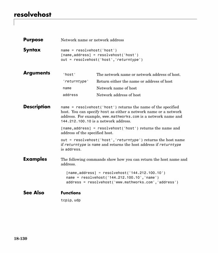
resolvehost
Purpose Network name or network address
Syntax name = resolvehost('host')[name,address] = resolvehost('host')out = resolvehost('host','returntype')
Arguments 'host' The network name or network address of host.
'returntype' Return either the name or address of host
name Network name of host
address Network address of host
Description name = resolvehost('host') returns the name of the specifiedhost. You can specify host as either a network name or a networkaddress. For example, www.mathworks.com is a network name and144.212.100.10 is a network address.
[name,address] = resolvehost('host') returns the name andaddress of the specified host.
out = resolvehost('host','returntype') returns the host nameif returntype is name and returns the host address if returntypeis address.
Examples The following commands show how you can return the host name andaddress.
[name,address] = resolvehost('144.212.100.10')name = resolvehost('144.212.100.10','name')address = resolvehost('www.mathworks.com','address')
See Also Functions
tcpip, udp
18-130

save
Purpose Save instrument objects and variables to MAT-file
Syntax save filenamesave filename obj1 obj2 ...
Arguments filename The MAT-file name.
obj1 obj2 ... Instrument objects or arrays of instrument objects.
Description save filename saves all MATLAB variables to the MAT-file filename.If an extension is not specified for filename, then a .mat extension isused.
save filename obj1 obj2 ... saves the instrument objects obj1obj2 ... to the MAT-file filename.
Remarks You can use save in the functional form as well as the command formshown above. When using the functional form, you must specify thefilename and instrument objects as strings. For example, to save theserial port object s to the file MySerial.mat,
s = serial('COM1');save('MySerial','s')
Any data that is associated with the instrument object is notautomatically stored in the MAT-file. For example, suppose there isdata in the input buffer for obj. To save that data to a MAT-file, youmust bring the data into the MATLAB workspace using one of thesynchronous read functions, and then save the data to the MAT-fileusing a separate variable name. You can also save data to a text filewith the record function.
You return objects and variables to the MATLAB workspace with theload command. Values for read-only properties are restored to theirdefault values upon loading. For example, the Status property isrestored to closed. To determine if a property is read-only, examine itsreference pages or use the propinfo function.
18-131

save
Examples This example illustrates how to use the command form and thefunctional form of save.
s = serial('COM1');set(s,'BaudRate',2400,'StopBits',1)save MySerial1 sset(s,'BytesAvailableFcn',@mycallback)save('MySerial2','s')
See Also Functions
instrhelp, load, propinfo, record
Properties
Status
18-132

scanstr
Purpose Read data from instrument, format as text, and parse
Syntax A = scanstr(obj)A = scanstr(obj,'delimiter')A = scanstr(obj,'delimiter','format')[A,count] = scanstr(...)[A,count,msg] = scanstr(...)
Arguments obj An interface object.
'delimiter' One or more delimiters used to parse the data.
'format' C language conversion specification.
A Data read from the instrument and formatted as text.
count The number of values read.
msg A message indicating if the read operation wasunsuccessful.
Description A = scanstr(obj) reads formatted data from the instrument connectedto obj, parses the data using both a comma and a semicolon delimiter,and returns the data to the cell array A. Each element of the cell arrayis determined to be either a double or a string.
A = scanstr(obj,'delimiter') parses the data into separatevariables based on the specified delimiter. delimiter can be a singlecharacter or a string array. If delimiter is a string array, then eachcharacter in the array is used as a delimiter.
A = scanstr(obj,'delimiter','format') converts the dataaccording to the specified format. A can be a matrix or a cell arraydepending on format. See the textread M-file help for complete details.format is a string containing C language conversion specifications.
Conversion specifications involve the % character and the conversioncharacters d, i, o, u, x, X, f, e, E, g, G, c, and s. See the sscanf file I/Oformat specifications or a C manual for complete details.
18-133

scanstr
If format is not specified, then the best format (either a double or astring) is chosen.
[A,count] = scanstr(...) returns the number of values read tocount.
[A,count,msg] = scanstr(...) returns a warning message to msg ifthe read operation did not complete successfully.
Remarks Before you can read data from the instrument, it must be connected toobj with the fopen function. A connected interface object has a Statusproperty value of open. An error is returned if you attempt to perform aread operation while obj is not connected to the instrument.
If msg is not included as an output argument and the read operation wasnot successful, then a warning message is returned to the command line.
The ValuesReceived property value is increased by the number ofvalues read — including the terminator — each time scanstr is issued.
Examples Create the GPIB object g associated with a National Instruments boardwith index 0 and primary address 2, and connect g to a Tektronix TDS210 oscilloscope.
g = gpib('ni',0,2);fopen(g)
Return identification information to separate elements of a cell arrayusing the default delimiters.
fprintf(g,'*IDN?');idn = scanstr(g)idn =
'TEKTRONIX''TDS 210'[ 0]'CF:91.1CT FV:v1.16 TDS2CM:CMV:v1.04'
18-134

scanstr
See Also Functions
fopen, fscanf, instrhelp, sscanf, textread
Properties
EOSCharCode, EOSMode, Status, Terminator, ValuesReceived
18-135

selftest
Purpose Run instrument self-test
Syntax out = selftest(obj)
Arguments obj A device object.
out The result of the self-test.
Description out = selftest(obj) runs the self-test for the instrument associatedwith the device object specified by obj. The result of the self-testis returned to out. Note that the test result will vary based on theinstrument.
18-136

serial
Purpose Create serial port object
Syntax obj = serial('port')obj = serial('port','PropertyName',PropertyValue,...)
Arguments 'port' The serial port name.
'PropertyName' A serial port property name.
PropertyValue A property value supported by PropertyName.
obj The serial port object.
Description obj = serial('port') creates a serial port object associated with theserial port specified by port. If port does not exist, or if it is in use,you will not be able to connect the serial port object to the instrumentwith the fopen function.
obj = serial('port','PropertyName',PropertyValue,...) createsa serial port object with the specified property names and propertyvalues. If an invalid property name or property value is specified, anerror is returned and the serial port object is not created.
Remarks At any time, you can use the instrhelp function to view a completelisting of properties and functions associated with serial port objects.
instrhelp serial
When you create a serial port object, these property values areautomatically configured:
• Type is given by serial.
• Name is given by concatenating Serial with the port specified in theserial function.
• Port is given by the port specified in the serial function.
18-137

serial
You can specify the property names and property values using anyformat supported by the set function. For example, you can useproperty name/property value cell array pairs. Additionally, you canspecify property names without regard to case, and you can make useof property name completion. For example, the following commandsare all valid.
s = serial('COM1','BaudRate',4800);s = serial('COM1','baudrate',4800);s = serial('COM1','BAUD',4800);
Before you can communicate with the instrument, it must be connectedto obj with the fopen function. A connected serial port object has aStatus property value of open. An error is returned if you attempt aread or write operation while obj is not connected to the instrument.You can connect only one serial port object to a given serial port.
Examples This example creates the serial port object s1 associated with the serialport COM1.
s1 = serial('COM1');
The Type, Name, and Port properties are automatically configured.
get(s1,{'Type','Name','Port'})ans =
'serial' 'Serial-COM1' 'COM1'
To specify properties during object creation,
s2 = serial('COM2','BaudRate',1200,'DataBits',7);
See Also Functions
fclose, fopen, propinfo
Properties
Name, Port, Status, Type
18-138

serialbreak
Purpose Send break to instrument
Syntax serialbreak(obj)serialbreak(obj,time)
Arguments obj A serial port object.
time The duration of the break, in milliseconds.
Description serialbreak(obj) sends a break of 10 milliseconds to the instrumentconnected to obj.
serialbreak(obj,time) sends a break to the instrument with aduration, in milliseconds, specified by time. Note that the duration ofthe break might be inaccurate under some operating systems.
Remarks For some instruments, the break signal provides a way to clear thehardware buffer.
Before you can send a break to the instrument, it must be connectedto obj with the fopen function. A connected serial port object has aStatus property value of open. An error is returned if you attempt tosend a break while obj is not connected to the instrument.
serialbreak is a synchronous function, and blocks the command lineuntil execution is complete.
If you issue serialbreak while data is being asynchronously written,an error is returned. In this case, you must call the stopasync functionor wait for the write operation to complete.
See Also Functions
fopen, stopasync
Properties
Status
18-139

set
Purpose Configure or display instrument object properties
Syntax set(obj)props = set(obj)set(obj,'PropertyName')props = set(obj,'PropertyName')set(obj,'PropertyName',PropertyValue,...)set(obj,PN,PV)set(obj,S)
Arguments obj An instrument object or an array of instrumentobjects.
'PropertyName' A property name for obj.
PropertyValue A property value supported by PropertyName.
PN A cell array of property names.
PV A cell array of property values.
S A structure with property names and propertyvalues.
props A structure array whose field names are theproperty names for obj, or cell array of possiblevalues.
Description set(obj) displays all configurable property values for obj. If a propertyhas a finite list of possible string values, then these values are alsodisplayed.
props = set(obj) returns all configurable properties and theirpossible values for obj to props. props is a structure whose field namesare the property names of obj, and whose values are cell arrays ofpossible property values. If the property does not have a finite set ofpossible values, then the cell array is empty.
18-140

set
set(obj,'PropertyName') displays the valid values for PropertyNameif it possesses a finite list of string values.
props = set(obj,'PropertyName') returns the valid values forPropertyName to props. props is a cell array of possible string valuesor an empty cell array if PropertyName does not have a finite list ofpossible values.
set(obj,'PropertyName',PropertyValue,...) configures multipleproperty values with a single command.
set(obj,PN,PV) configures the properties specified in the cell array ofstrings PN to the corresponding values in the cell array PV. PN must be avector. PV can be m-by-n where m is equal to the number of instrumentobjects in obj and n is equal to the length of PN.
set(obj,S) configures the named properties to the specified values forobj. S is a structure whose field names are instrument object properties,and whose field values are the values of the corresponding properties.
Remarks You can use any combination of property name/property value pairs,structure arrays, and cell arrays in one call to set. Additionally, you canspecify a property name without regard to case, and you can make useof property name completion. For example, if g is a GPIB object, thenthe following commands are all valid.
set(g,'EOSMode')set(g,'eosmode')set(g,'EOSM')
Examples This example illustrates some of the ways you can use set to configureor return property values for the GPIB object g.
g = gpib('ni',0,1);set(g,'EOSMode','read','OutputBufferSize',50000)set(g,{'EOSCharCode','RecordName'},{13,'sydney.txt'})set(g,'EOIMode')[ {on} | off ]
18-141

set
See Also Functions
get, instrhelp, propinfo
18-142

size
Purpose Size of instrument object array
Syntax d = size(obj)[m,n] = size(obj)[m1,m2,m3,...,mn] = size(obj)m = size(obj,dim)
Arguments obj An instrument object or an array of instrumentobjects.
dim The dimension of obj.
d The number of rows and columns in obj.
m The number of rows in obj, or the length of thedimension specified by dim.
n The number of columns in obj.
m1,m2,...,mn The length of the first N dimensions of obj.
Description d = size(obj) returns the two-element row vector d containing thenumber of rows and columns in obj.
[m,n] = size(obj) returns the number of rows and columns inseparate output variables.
[m1,m2,m3,...,mn] = size(obj) returns the length of the first ndimensions of obj.
m = size(obj,dim) returns the length of the dimension specified bythe scalar dim. For example, size(obj,1) returns the number of rows.
See Also Functions
instrhelp, length
18-143

spoll
Purpose Perform serial poll
Syntax out = spoll(obj)out = spoll(obj,val)
Arguments obj A GPIB object or an array of GPIB objects.
val A numeric array containing the indices of the objects inobj, that must be ready for servicing before control isreturned to MATLAB.
out The GPIB objects ready for servicing.
Description out = spoll(obj) performs a serial poll on the instruments associatedwith obj. out contains the GPIB objects that are ready for servicing. Ifno objects are ready for servicing, then out is empty.
out = spoll(obj,val) performs a serial poll and waits until theinstruments specified by val are ready for servicing. An error isreturned if a value specified in val does not match an index value in obj.
Using this syntax, spoll blocks access to the MATLAB command lineuntil the objects specified by val are ready for servicing, or a timeoutoccurs for each object specified by val. The timeout period is specifiedby the Timeout property.
Remarks Serial polling is a method of obtaining specific information from GPIBobjects when they request service. When you perform a serial poll, outcontains the GPIB object that has asserted its service request (SRQ)line.
If obj is an array of GPIB objects
• Each element of obj must have the same BoardIndex property value.
• Each element of obj is polled to determine if the instrument is readyfor servicing.
18-144

spoll
Examples If obj is a four-element array and val is set to [1 3], then spoll willblock access to the MATLAB command line until the instrumentsconnected to the first and third GPIB objects have both asserted theirSRQ line, or a timeout occurs.
See Also Functions
gpib, length
Properties
BoardIndex, Timeout
18-145

stopasync
Purpose Stop asynchronous read and write operations
Syntax stopasync(obj)
Arguments obj An interface object or an array of interface objects.
Description stopasync(obj) stops any asynchronous read or write operation that isin progress for obj.
Remarks You can write data asynchronously using the fprintf or fwritefunctions. You can read data asynchronously using the readasyncfunction, or by configuring the ReadAsyncMode property to continuous(serial port, TCPIP, UDP, and VISA-serial objects). In-progressasynchronous operations are indicated by the TransferStatus property.
If obj is an array of interface objects and one of the objects cannot bestopped, the remaining objects in the array are stopped and a warningis returned. After an object stops,
• Its TransferStatus property is configured to idle.
• Its ReadAsyncMode property is configured to manual (serial port,TCPIP, UDP, and VISA-serial objects).
• The data in its output buffer is flushed.
Data in the input buffer is not flushed. You can return this data to theMATLAB workspace using any of the synchronous read functions. Ifyou execute the readasync function, or configure the ReadAsyncModeproperty to continuous, then the new data is appended to the existingdata in the input buffer.
See Also Functions
fprintf, fwrite, readasync
18-146

stopasync
Properties
ReadAsyncMode, TransferStatus
18-147

tcpip
Purpose Create TCPIP object
Syntax obj = tcpip('rhost')obj = tcpip('rhost',rport)obj = tcpip(...,'PropertyName',PropertyValue,...)
Arguments 'rhost' The remote host.
rport The remote port.
'PropertyName' A TCPIP property name.
PropertyValue A property value supported by PropertyName.
obj The TCPIP object.
Description obj = tcpip('rhost') creates a TCPIP object, obj, associated withremote host rhost and the default remote port value of 80.
obj = tcpip('rhost',rport) creates a TCPIP object with remoteport value rport.
obj = tcpip(...,'PropertyName',PropertyValue,...) creates aTCPIP object with the specified property name/property value pairs.If an invalid property name or property value is specified, the objectis not created.
Remarks At any time, you can use the instrhelp function to view a completelisting of properties and functions associated with TCPIP objects.
instrhelp tcpip
When you create a TCPIP object, these property values areautomatically configured:
• Type is given by tcpip.
• Name is given by concatenating TCPIP with the remote host namespecified in the tcpip function.
18-148

tcpip
• RemoteHost and RemotePort are given by the values specified inthe tcpip function.
You can specify the property names and property values using anyformat supported by the set function. For example, you can useproperty name/property value cell array pairs. Additionally, you canspecify property names without regard to case, and you can make useof property name completion. For example, the following commandsare all valid.
t = tcpip('144.212.113.252','InputBufferSize',1024);t = tcpip('144.212.113.252','inputbuffersize',1024);t = tcpip('144.212.113.252','INPUT',1024);
When the TCPIP object is constructed, the Status property valueis closed. Once the object is connected to the host with the fopenfunction, the Status property is configured to open.
The default local host in multihome hosts is the system’s default. TheLocalPort property defaults to a value of [] and it causes any free localport to be used. LocalPort is updated when fopen is issued.
Examples Start a TCP/IP echo server and create a TCPIP object.
echotcpip('on',4012)t = tcpip('localhost',4012);
Connect the TCPIP object to the host.
fopen(t)
Write to the host and read from the host.
fwrite(t,65:74)A = fread(t, 10);
18-149

tcpip
Disconnect the TCPIP object from the host and stop the echo server.
fclose(t)echotcpip('off')
See Also Functions
fopen, sendmail, udp, urlread, urlwrite
Properties
LocalHost, LocalPort, LocalPortMode, Name, RemoteHost,RemotePort, Status, Type
18-150

tmtool
Purpose Open Test & Measurement Tool
Syntax tmtool
Description tmtool starts the Test & Measurement Tool. The Test & MeasurementTool displays the resources (hardware, drivers, interfaces, etc.)accessible to the toolboxes that support the tool, and enables you toconfigure and communicate with those resources.
You use the Test & Measurement Tool to manage your instrumentcontrol session. This tool enables you to
• Search for available hardware and drivers
• Create instrument objects
• Connect to an instrument
• Configure instrument settings
• Write data to an instrument
• Read data from an instrument
• Save a log of your session as an M-file
For a full description of the Test & Measurement Tool with examples,see Chapter 13, “Test & Measurement Tool”.
See Also midedit, midtest
18-151

trigger
Purpose Send trigger message to instrument
Syntax trigger(obj)
Arguments obj A GPIB, VISA-GPIB, or VISA-VXI object.
Description trigger(obj) sends a trigger message to the instrument connectedto obj.
Remarks Before you can use trigger, obj must be connected to the instrumentwith the fopen function. A connected interface object has a Statusproperty value of open. An error is returned if you attempt to usetrigger while obj is not connected to the instrument.
For GPIB and VISA-GPIB objects, the Group Execute Trigger (GET)message is sent to the instrument.
For VISA-VXI objects, if the TriggerType property is configured tosoftware, the Word Serial Trigger command is sent to the instrument.If TriggerType is configured to hardware, a hardware trigger is sent onthe line specified by the TriggerLine property.
See Also Functions
fopen
Properties
Status, TriggerLine, TriggerType
18-152

udp
Purpose Create UDP object
Syntax obj = udp('')obj = udp('rhost')obj = udp('rhost',rport)obj = udp(...,'PropertyName',PropertyValue,...)
Arguments 'rhost' The remote host.
rport The remote port.
'PropertyName' A UDP property name.
PropertyValue A property value supported by PropertyName.
obj The UDP object.
Description obj = udp('') creates a UDP object, obj, not associated with a remotehost. obj = udp('rhost') creates a UDP object associated withremote host rhost.
obj = udp('rhost',rport) creates a UDP object with remote portvalue, rport. The default remote port is 9090.
obj = udp(...,'PropertyName',PropertyValue,...) creates a UDPobject with the specified property name/property value pairs. If aninvalid property name or property value is specified, the object is notcreated.
Remarks At any time, you can use the instrhelp function to view a completelisting of properties and functions associated with UDP objects.
instrhelp udp
When you create a UDP object, these properties are automaticallyconfigured:
• Type is given by udp.
18-153

udp
• Name is given by concatenating UDP with the remote host namespecified in the udp function.
• RemoteHost and RemotePort are given by the values specified inthe udp function.
You can specify the property names and property values using anyformat supported by the set function. For example, you can useproperty name/property value cell array pairs. Additionally, you canspecify property names without regard to case, and you can make useof property name completion. For example, the following commandsare all valid.
u = udp('144.212.113.252','InputBufferSize',1024);u = udp('144.212.113.252','inputbuffersize',1024);u = udp('144.212.113.252','INPUT',1024);
The UDP object must be bound to the local socket with the fopenfunction. The default remote port is 9090. The default local host inmultihome hosts is the system’s default. The LocalPort propertydefaults to a value of [] and it causes any free local port to be used.LocalPort is updated when fopen is issued. When the UDP object isconstructed, the Status property value is closed. Once the object isbound to the local socket with fopen, Status is configured to open.
The maximum packet size for reading is 8192 bytes. The input buffercan hold as many packets as defined by the InputBufferSize propertyvalue. You can write any data size to the output buffer. The data will besent in packets of at most 4096 bytes.
Examples Start the echo server and create a UDP object.
echoudp('on',4012)u = udp('127.0.0.1',4012);
Connect the UDP object to the host.
fopen(u)
18-154

udp
Write to the host and read from the host.
fwrite(u,65:74)A = fread(u,10);
Stop the echo server and disconnect the UDP object from the host.
echoudp('off')fclose(u)
See Also Functions
fopen
Properties
LocalHost, LocalPort, LocalPortMode, Name, RemoteHost,RemotePort, Status, Type
18-155

update
Purpose Update entry of IVI configuration store object
Syntax update(obj, 'type', 'name', 'P1', V1, ...)update(obj, struct)
Arguments obj IVI configuration store object.
'type' Type of entry; type can be HardwareAsset,DriverSession, or LogicalName.
'name' Name of the DriverSession, HardwareAsset, orLogicalName to be updated.
'P1' First parameter for updated entry; otherparameter-value pairs may follow.
V1 Value for first parameter.
struct Structure defining entry fields to be updated.
Description update(obj, 'type', 'name', 'P1', V1, ...) updates an entry oftype, type, with name, name, in IVI configuration store object, obj,using the specified parameter-value pairs. type can be HardwareAsset,DriverSession, or LogicalName.
If an entry of type, type with name, name does not exist, an error willoccur.
Valid parameters for a DriverSession are listed below. The defaultvalue for on/off parameters is off.
Parameter Value Description
Name string A unique name for the driversession.
SoftwareModule string The name of a software moduleentry in the configuration store.
18-156

update
Parameter Value Description
HardwareAsset string The name of a hardware assetentry in the configuration store.
Description Any string Description of driver session
VirtualNames structure A struct array containing virtualname mappings
Cache on/off Enable caching if the driversupports it.
DriverSetup Any string This value is software moduledependent
InterchangeCheck on/off Enable driver interchangeabilitychecking, if supported
QueryInstrStatus on/off Enable instrument statusquerying by the driver
RangeCheck on/off Enable extended range checkingby the driver, if supported
RecordCoercions on/off Enable recording of coercions bythe driver, if supported
Simulate on/off Enable simulation by the driver
Valid fields for HardwareAsset are
Parameter Value Description
Name string A unique name for thehardware asset
Description Anystring
Description of hardware asset
IOResourceDescriptor string The I/O address of thehardware asset
18-157

update
Valid fields for LogicalName are
Parameter Value Description
Name string A unique name for the logicalname
Description Any string Description of hardware asset
Session string The name of a driver sessionentry in the configuration store
update(obj, struct) updates the entry using the fields in struct. Ifan entry with the type and name field in struct does not exist, an errorwill occur. Note that the name field cannot be updated using this syntax.
Examples Update the Description parameter of the driver session namedScopeSession in the IVI configuration store object named c.
c = iviconfigurationstore;update(c, 'DriverSession', 'ScopeSession', 'Description', ...'A session.');
See Also Functions
iviconfigurationstore, iviconfigurationstore/add,iviconfigurationstore/commit, iviconfigurationstore/remove
18-158
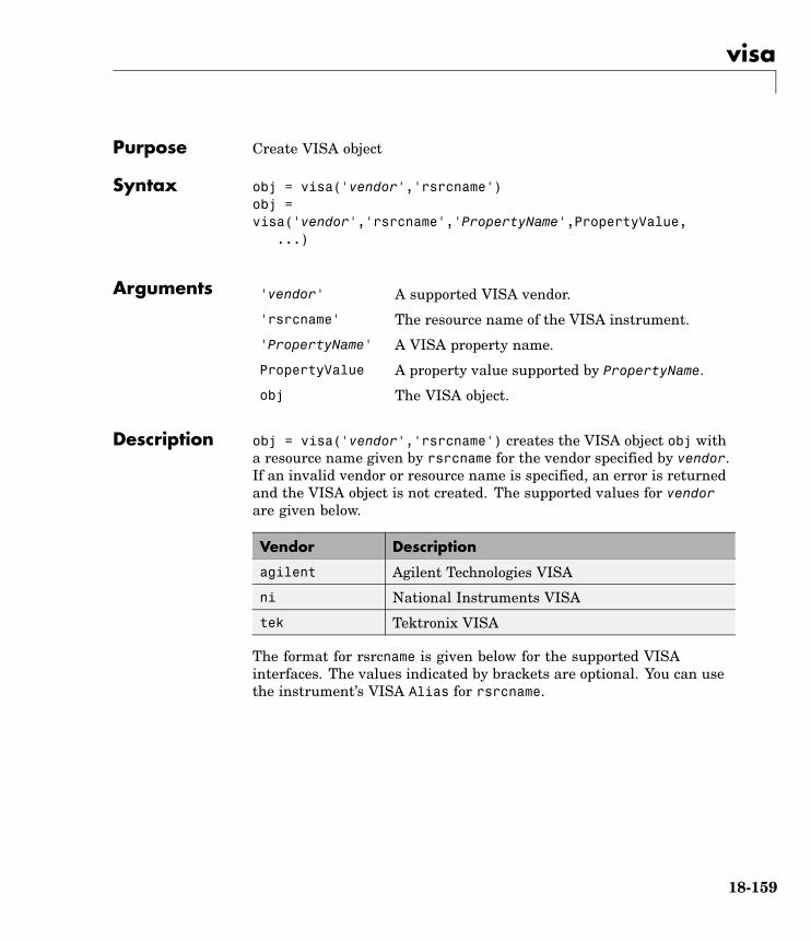
visa
Purpose Create VISA object
Syntax obj = visa('vendor','rsrcname')obj =visa('vendor','rsrcname','PropertyName',PropertyValue,
...)
Arguments 'vendor' A supported VISA vendor.
'rsrcname' The resource name of the VISA instrument.
'PropertyName' A VISA property name.
PropertyValue A property value supported by PropertyName.
obj The VISA object.
Description obj = visa('vendor','rsrcname') creates the VISA object obj witha resource name given by rsrcname for the vendor specified by vendor.If an invalid vendor or resource name is specified, an error is returnedand the VISA object is not created. The supported values for vendorare given below.
Vendor Description
agilent Agilent Technologies VISA
ni National Instruments VISA
tek Tektronix VISA
The format for rsrcname is given below for the supported VISAinterfaces. The values indicated by brackets are optional. You can usethe instrument’s VISA Alias for rsrcname.
18-159

visa
Interface Resource Name
GPIB GPIB[board]::primary_address[::secondary_address]::INSTR
GPIB-VXI GPIB-VXI[chassis]::VXI_logical_address::INSTR
RSIB RSIB::remote_host::INSTR (provided by NI VISA only)
Serial ASRL[port_number]::INSTR
TCPIP TCPIP[board]::remote_host[::lan_device_name]::INSTR
USB USB[board]::manid::model_code::serial_No[::interface_No]::INSTR
VXI VXI[chassis]::VXI_logical_address::INSTR
The rsrcname parameters are described below.
Parameter Description
board Board index (optional — defaults to 0)
chassis VXI chassis index (optional — defaults to 0)
interface_No USB interface
lan_device_name Local Area Network (LAN) device name(optional — defaults to inst0)
manid Manufacturer ID of the USB instrument
model_code Model code for the USB instrument
port_number Serial port number (optional — defaults to 1)
primary_address Primary address of the GPIB instrument
remote_host Host name or IP address of the instrument
secondary_address Secondary address of the GPIB instrument(optional — defaults to 0)
serial_No Index of the instrument on the USB hub
VXI_logical_address Logical address of the VXI instrument
18-160

visa
obj =visa('vendor','rsrcname','PropertyName',PropertyValue,...)creates the VISA object with the specified property names and propertyvalues. If an invalid property name or property value is specified, anerror is returned and the VISA object is not created.
Remarks At any time, you can use the instrhelp function to view a completelisting of properties and functions associated with VISA objects.
instrhelp visa
You can specify the property names and property values using anyformat supported by the set function. For example, you can useproperty name/property value cell array pairs. Additionally, you canspecify property names without regard to case, and you can make useof property name completion. For example, the following commandsare all valid.
v = visa('ni','GPIB0::1::INSTR','SecondaryAddress', 96);v = visa('ni','GPIB0::1::INSTR','secondaryaddress', 96);v = visa('ni','GPIB0::1::INSTR','SECOND', 96);
Before you can communicate with the instrument, it must be connectedto obj with the fopen function. A connected VISA object has a Statusproperty value of open. An error is returned if you attempt a read orwrite operation while obj is not connected to the instrument. Youcannot connect multiple VISA objects to the same instrument.
Creating a VISA-GPIB Object
When you create a VISA-GPIB object, these properties are automaticallyconfigured:
• Type is given by visa-gpib.
• Name is given by concatenating VISA-GPIB with the board index, theprimary address, and the secondary address.
18-161

visa
• BoardIndex, PrimaryAddress, SecondaryAddress, and RsrcName aregiven by the values specified during object creation.
Creating a VISA-GPIB-VXI Object
When you create a VISA-GPIB-VXI object, these properties areautomatically configured:
• Type is given by visa-gpib-vxi.
• Name is given by concatenating VISA-GPIB-VXI with the chassis indexand the logical address specified in the visa function.
• ChassisIndex, LogicalAddress, and RsrcName are given by thevalues specified during object creation.
• BoardIndex, PrimaryAddress, and SecondaryAddress are given bythe visa driver after the object is connected to the instrument withfopen.
Creating a VISA-RSIB Object
When you create a VISA-RSIB object, these properties are automaticallyconfigured:
• Type is given by visa-rsib.
• Name is given by concatenating VISA-RSIB with the remote hostspecified in the visa function.
• RemoteHost and RsrcName are given by the values specified duringobject creation.
Creating a VISA-Serial Object
When you create a VISA-serial object, these properties are automaticallyconfigured:
• Type is given by visa-serial.
• Name is given by concatenating VISA-Serial with the port specifiedin the visa function.
18-162

visa
• Port and RsrcName are given by the values specified during objectcreation.
Creating a VISA-TCPIP Object
When you create a VISA-TCPIP object, these properties areautomatically configured:
• Type is given by visa-tcpip.
• Name is given by concatenating VISA-TCPIP with the board index,remote host, and LAN device name specified in the visa function.
• BoardIndex, RemoteHost, LANNAme, and RsrcName are given by thevalues specified during object creation.
Creating a VISA-USB Object
When you create a VISA-USB object, these properties are automaticallyconfigured:
• Type is given by visa-usb.
• Name is given by concatenating VISA-USB with the board index,manufacturer ID, model code, serial number, and interface numberspecified in the visa function.
• BoardIndex, ManufacturerID, ModelCode, SerialNumber,InterfaceIndex, and RsrcName are given by the values specifiedduring object creation.
Creating a VISA-VXI Object
When you create a VISA-VXI object, these properties are automaticallyconfigured:
• Type is given by visa-vxi.
• Name is given by concatenating VISA-VXI with the chassis index andthe logical address specified in the visa function.
• ChassisIndex, LogicalAddress, and RsrcName are given by thevalues specified during object creation.
18-163

visa
Examples Create a VISA-serial object connected to serial port COM1 usingNational Instruments VISA interface.
vs = visa('ni','ASRL1::INSTR');
Create a VISA-GPIB object connected to board 0 with primary address1 and secondary address 30 using Agilent Technologies VISA interface.
vg = visa('agilent','GPIB0::1::30::INSTR');
Create a VISA-VXI object connected to a VXI instrument located atlogical address 8 in the first VXI chassis.
vv = visa('agilent','VXI0::8::INSTR');
Create a VISA-GPIB-VXI object connected to a GPIB-VXI instrumentlocated at logical address 72 in the second VXI chassis.
vgv = visa('agilent','GPIB-VXI1::72::INSTR');
Create a VISA-RSIB object connected to an instrument configured withIP address 192.168.1.33.
vr = visa('ni', 'RSIB::192.168.1.33::INSTR')
Create a VISA-TCPIP object connected to an instrument configuredwith IP address 216.148.60.170.
vt = visa('tek', 'TCPIP::216.148.60.170::INSTR')
Create a VISA-USB object connected to a USB instrument withmanufacturer ID 0x1234, model code 125, and serial number A22-5.
vu = visa('agilent', 'USB::0x1234::125::A22-5::INSTR')
See Also Functions
fclose, fopen, instrhelp, instrhwinfo
18-164

visa
Properties
BoardIndex, ChassisIndex, InterfaceIndex, LANName,LogicalAddress, ManufacturerID, ModelCode, Name, Port,PrimaryAddress, RsrcName, SecondaryAddress, SerialNumber,Status, Type
18-165

visa
18-166

19
Properties — By Category
Interface Object Base Properties(p. 19-2)
Apply to all interface objects
Interface-Specific Properties (p. 19-5) Apply to instrument objects ofparticular interface type
Device Object Base Properties(p. 19-13)
Apply to all device objects
IVI Configuration Store ObjectProperties (p. 19-14)
Apply to IVI configuration storeobjects

19 Properties — By Category
Interface Object Base Properties
Writing Data (p. 19-2) Output buffer parameters, timeout,status
Reading Data (p. 19-2) Input buffer parameters, timeout,status
Recording Data (p. 19-3) Record file parameters, status
Callbacks (p. 19-3) M-file callback functions to executewhen specific events occur
General Purpose (p. 19-4) Object description, byte order, status
Writing Data
BytesToOutput Number of bytes currently in outputbuffer
OutputBufferSize Specify size of output buffer in bytes
Timeout Specify waiting time to completeread or write operation
TransferStatus Status of whether asynchronousread or write operation is in progress
ValuesSent Total number of values written toinstrument
Reading Data
BytesAvailable Number of bytes available in inputbuffer
InputBufferSize Specify size of input buffer in bytes
Timeout Specify waiting time to completeread or write operation
19-2

Interface Object Base Properties
TransferStatus Status of whether asynchronousread or write operation is in progress
ValuesReceived Total number of values read frominstrument
Recording Data
RecordDetail Specify amount of information savedto record file
RecordMode Specify whether data and eventinformation are saved to one or tomultiple record files
RecordName Specify name of record file
RecordStatus Status of whether data and eventinformation are saved to record file
Callbacks
BytesAvailableFcn Specify M-file callback function toexecute when specified number ofbytes are available in input buffer,or terminator is read
BytesAvailableFcnCount Specify number of bytes that must beavailable in input buffer to generatebytes-available event
BytesAvailableFcnMode Specify whether bytes-availableevent is generated after specifiednumber of bytes are available ininput buffer, or after terminator isread
ErrorFcn Specify M-file callback function toexecute when error event occurs
19-3

19 Properties — By Category
OutputEmptyFcn Specify M-file callback function toexecute when output buffer is empty
TimerFcn Specify M-file callback function toexecute when predefined periodpasses
TimerPeriod Specify period between timer events
General Purpose
ByteOrder Specify byte order of instrument
Name Specify descriptive name forinstrument object
ObjectVisibility Control access to instrument object
Status Status of whether object is connectedto instrument
Tag Specify label to associate withinstrument object
Type Instrument object type
UserData Specify data to associate withinstrument object
19-4

Interface-Specific Properties
Interface-Specific Properties
GPIB (p. 19-5) Communication address, busconfiguration, status
Serial Port (p. 19-6) Communication settings, dataformat, signals and pins
TCPIP (p. 19-7) Host and port information,terminator character
UDP (p. 19-7) Host and port information,datagrams, terminator character
VISA-GPIB (p. 19-8) Resource name, communicationaddress, bus configuration, status
VISA-GPIB-VXI (p. 19-8) Resource name, VXI memory,chassis information, communicationaddress, bus configuration, status
VISA-RSIB (p. 19-9) Resource name, communicationaddress, communication settings
VISA-Serial (p. 19-10) Resource name, communicationsettings, data format, signals andpins
VISA-TCPIP (p. 19-10) Resource name, communicationaddress, communication settings
VISA-USB (p. 19-11) Resource name, communicationaddress, communication settings
VISA-VXI (p. 19-11) Resource name, VXI memory, chassisinformation, status
GPIB
BoardIndex Specify index number of interfaceboard
BusManagementStatus State of GPIB bus management lines
19-5

19 Properties — By Category
CompareBits Specify number of bits that mustmatch EOS character to completeread operation, or to assert EOI line
EOIMode Specify if EOI line is asserted at endof write operation
EOSCharCode Specify EOS character
EOSMode Specify when EOS character iswritten or read
HandshakeStatus State of GPIB handshake lines
PrimaryAddress Specify primary address of GPIBinstrument
SecondaryAddress Specify secondary address of GPIBinstrument
Serial Port
BaudRate Specify bit transmit rate
BreakInterruptFcn Specify M-file callback function toexecute when break-interrupt eventoccurs
DataBits Specify number of data bits totransmit
DataTerminalReady Specify state of DTR pin
FlowControl Specify data flow control method touse
Parity Specify type of parity checking
PinStatus State of CD, CTS, DSR, and RI pins
PinStatusFcn Specify M-file callback function toexecute when CD, CTS, DSR, or RIpin changes state
Port Specify platform-specific serial portname
19-6

Interface-Specific Properties
ReadAsyncMode Specify whether asynchronous readoperation is continuous or manual
RequestToSend Specify state of RTS pin
StopBits Specify number of bits used toindicate end of byte
Terminator Specify terminator character
TCPIP
LocalHost Specify local host
LocalPort Specify local host port for connection
LocalPortMode Specify local host port selection mode
ReadAsyncMode Specify whether asynchronous readoperation is continuous or manual
RemoteHost Specify remote host
RemotePort Specify remote host port forconnection
Terminator Specify terminator character
TransferDelay Specify use of TCP segment transferalgorithm
UDP
DatagramAddress IP dotted decimal address of receiveddatagram sender
DatagramPort Port number of datagram sender
DatagramReceivedFcn Specify M-file callback function toexecute when datagram is received
DatagramTerminateMode Configure terminate read modewhen reading datagrams
LocalHost Specify local host
19-7

19 Properties — By Category
LocalPort Specify local host port for connection
LocalPortMode Specify local host port selection mode
ReadAsyncMode Specify whether asynchronous readoperation is continuous or manual
RemoteHost Specify remote host
RemotePort Specify remote host port forconnection
Terminator Specify terminator character
VISA-GPIB
BoardIndex Specify index number of interfaceboard
EOIMode Specify if EOI line is asserted at endof write operation
EOSCharCode Specify EOS character
EOSMode Specify when EOS character iswritten or read
PrimaryAddress Specify primary address of GPIBinstrument
RsrcName Resource name for VISA instrument
SecondaryAddress Specify secondary address of GPIBinstrument
VISA-GPIB-VXI
BoardIndex Specify index number of interfaceboard
ChassisIndex Specify index number of VXI chassis
EOIMode Specify if EOI line is asserted at endof write operation
19-8

Interface-Specific Properties
EOSCharCode Specify EOS character
EOSMode Specify when EOS character iswritten or read
LogicalAddress Specify logical address of VXIinstrument
MappedMemoryBase Base memory address of mappedmemory
MappedMemorySize Size of mapped memory for low-levelread and write operations
MemoryBase Base address of A24 or A32 space
MemoryIncrement Specify whether VXI register offsetincrements after data is transferred
MemorySize Size of memory requested in A24 orA32 address space
MemorySpace Address space used by instrument
PrimaryAddress Specify primary address of GPIBinstrument
RsrcName Resource name for VISA instrument
SecondaryAddress Specify secondary address of GPIBinstrument
Slot Slot location of VXI instrument
VISA-RSIB
EOIMode Specify if EOI line is asserted at endof write operation
RemoteHost Specify remote host
19-9

19 Properties — By Category
VISA-Serial
BaudRate Specify bit transmit rate
DataBits Specify number of data bits totransmit
DataTerminalReady Specify state of DTR pin
FlowControl Specify data flow control method touse
Parity Specify type of parity checking
PinStatus State of CD, CTS, DSR, and RI pins
Port Specify platform-specific serial portname
ReadAsyncMode Specify whether asynchronous readoperation is continuous or manual
RequestToSend Specify state of RTS pin
RsrcName Resource name for VISA instrument
StopBits Specify number of bits used toindicate end of byte
Terminator Specify terminator character
VISA-TCPIP
BoardIndex Specify index number of interfaceboard
EOIMode Specify if EOI line is asserted at endof write operation
EOSCharCode Specify EOS character
EOSMode Specify when EOS character iswritten or read
LANName Specify LAN device name
RemoteHost Specify remote host
19-10

Interface-Specific Properties
VISA-USB
BoardIndex Specify index number of interfaceboard
EOIMode Specify if EOI line is asserted at endof write operation
EOSCharCode Specify EOS character
EOSMode Specify when EOS character iswritten or read
InterfaceIndex Specify USB interface number
ManufacturerID Specify manufacturer ID of USBinstrument
ModelCode Specify model code of USBinstrument
SerialNumber Specify index of USB instrument onUSB hub
VISA-VXI
ChassisIndex Specify index number of VXI chassis
EOIMode Specify if EOI line is asserted at endof write operation
EOSCharCode Specify EOS character
EOSMode Specify when EOS character iswritten or read
InterruptFcn Specify M-file callback function toexecute when interrupt event occurs
LogicalAddress Specify logical address of VXIinstrument
MappedMemoryBase Base memory address of mappedmemory
19-11

19 Properties — By Category
MappedMemorySize Size of mapped memory for low-levelread and write operations
MemoryBase Base address of A24 or A32 space
MemoryIncrement Specify whether VXI register offsetincrements after data is transferred
MemorySize Size of memory requested in A24 orA32 address space
MemorySpace Address space used by instrument
RsrcName Resource name for VISA instrument
Slot Slot location of VXI instrument
TriggerFcn Specify M-file callback function toexecute when trigger event occurs
TriggerLine Specify trigger line on VXIinstrument
TriggerType Specify trigger type
19-12
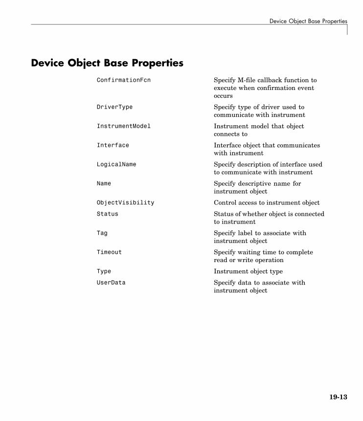
Device Object Base Properties
Device Object Base PropertiesConfirmationFcn Specify M-file callback function to
execute when confirmation eventoccurs
DriverType Specify type of driver used tocommunicate with instrument
InstrumentModel Instrument model that objectconnects to
Interface Interface object that communicateswith instrument
LogicalName Specify description of interface usedto communicate with instrument
Name Specify descriptive name forinstrument object
ObjectVisibility Control access to instrument object
Status Status of whether object is connectedto instrument
Tag Specify label to associate withinstrument object
Timeout Specify waiting time to completeread or write operation
Type Instrument object type
UserData Specify data to associate withinstrument object
19-13

19 Properties — By Category
IVI Configuration Store Object PropertiesActualLocation Configuration store file used by IVI
configuration store object
DriverSessions Array of driver sessions contained inIVI configuration store
HardwareAssets Array of hardware assets containedin IVI configuration store
LogicalNames Array of logical names contained inIVI configuration store
MasterLocation Full pathname of masterconfiguration store file
Name (iviconfigurationstore) Name of IVI configuration server
ProcessLocation Configuration store file for processto use if master configuration storeis not used
PublishedAPIs Array of published APIs in IVIconfiguration store
Revision IVI configuration store version
ServerDescription IVI configuration store serverdescription
Sessions Array of driver sessions in IVIconfiguration store
SoftwareModules Array of software modules in IVIconfiguration store
SpecificationVersion IVI configuration server specificationversion that this server revisioncomplies with
Vendor IVI configuration server vendor
19-14

20
Properties — AlphabeticalList

ActualLocation
Purpose Configuration store file used by IVI configuration store object
Description ActualLocation reflects the location of the IVI configuration storeactually being used. It is either the master configuration store, or theProcessLocation if an alternative to the master store was specifiedwhen the IVI configuration store object was created.
Characteristics Usage IVI configuration store object
Read only Always
Data type String
Values The default value is the master configuration store.
See Also Functions
commit
Properties
MasterLocation, ProcessLocation
20-2

Alias
Purpose Alias of resource name for VISA instrument
Description Alias indicates the alias for the resource name for a VISA instrument.When you create a VISA object, you can specify either the resourcename for a VISA instrument or an alias for the resource name. If analias is specified, Alias is automatically assigned the value specifiedin the VISA function. If a resource name is specified and the resourcename has an alias, Alias is updated with the alias value. If the resourcename does not have an alias, Alias is an empty string.
Characteristics Usage VISA object
Read only Always
Data type String
Values The default value is an empty string.
Remarks You set the alias for a resource name using vender-supplied tools. Youdo not set an alias in MATLAB. When you create the VISA object inMATLAB, the Alias property of the object takes on the value of theresource name alias. You do not directly set the value of this property.
National Instruments’ Measurement & Automation Explorer (MAX) isone example of a graphical interface tool for setting a VISA alias inNI-VISA. In this tool, select Tools > NI-VISA > Alias Editor to edit,add, or clear aliases. When you have your aliases defined, you can usethem in MATLAB to access your resources.
See Also Functions
visa
Properties
RsrcName
20-3

BaudRate
Purpose Specify bit transmit rate
Description You configure BaudRate as bits per second. The transferred bits includethe start bit, the data bits, the parity bit (if used), and the stop bits.However, only the data bits are stored.
The baud rate is the rate at which information is transferred in acommunication channel. In the serial port context, "9600 baud" meansthat the serial port is capable of transferring a maximum of 9600 bitsper second. If the information unit is one baud (one bit), then the bitrate and the baud rate are identical. If one baud is given as 10 bits, (forexample, eight data bits plus two framing bits), the bit rate is still 9600but the baud rate is 9600/10, or 960. You always configure BaudRate asbits per second. Therefore, in the above example, set BaudRate to 9600.
Note Both the computer and the instrument must be configured to thesame baud rate before you can successfully read or write data.
Your system computes the acceptable rates by taking the baud base,which is determined by your serial port, and dividing it by a positivewhole number divisor . The system will try to find the best match bymodifying the divisor. For example, if:
baud base = 115200 bits per seconddivisors = 1,2,3,4,5 .Possible BaudRates = 115200, 57600, 38400, 28800, 23040 .
Your system may further limit the available baud rates to conform tospecific conventions or standards. In the above example, for instance,23040 bits/sec may not be available on all systems.
20-4

BaudRate
Characteristics Usage Serial port, VISA-serial
Read only Never
Data type Double
Values The default value is 9600.
See Also Properties
DataBits, Parity, StopBits
20-5

BoardIndex
Purpose Specify index number of interface board
Description You configure BoardIndex to be the index number of the GPIB board,USB board, or TCP/IP board associated with your instrument. Whenyou create a GPIB, VISA-GPIB, VISA-GPIB-VXI, VISA-TCPIP, orVISA-USB object, BoardIndex is automatically assigned the valuespecified in the gpib or visa function.
For GPIB objects, the Name property is automatically updated toreflect the BoardIndex value. For VISA-GPIB, VISA-GPIB-VXI,VISA-TCPIP, or VISA-USB objects, the Name and RsrcName propertiesare automatically updated to reflect the BoardIndex value.
You can configure BoardIndex only when the object is disconnectedfrom the instrument. You disconnect a connected object with the fclosefunction. A disconnected object has a Status property value of closed.
Characteristics Usage GPIB, VISA-GPIB, VISA-GPIB-VXI, VISA-TCPIP,VISA-USB
Read only While open (GPIB, VISA-GPIB), always(VISA-GPIB-VXI, VISA-TCPIP, VISA-USB)
Data type Double
Values The value is defined after the instrument object is created.
Examples Suppose you create a VISA-GPIB object associated with board 4,primary address 1, and secondary address 8.
vg = visa('agilent','GPIB4::1::8::INSTR');
The BoardIndex, Name, and RsrcName properties reflect the GPIB boardindex number.
get(vg,{'BoardIndex','Name','RsrcName'})ans =
[4] 'VISA-GPIB4-1-8' 'GPIB4::1::8::INSTR'
20-6

BoardIndex
See Also Functions
fclose, gpib, visa
Properties
Name, RsrcName, Status
20-7

BreakInterruptFcn
Purpose Specify M-file callback function to execute when break-interrupt eventoccurs
Description You configure BreakInterruptFcn to execute an M-file callbackfunction when a break-interrupt event occurs. A break-interrupt eventis generated by the serial port when the received data is in an off (space)state longer than the transmission time for one byte.
Note A break-interrupt event can be generated at any time during theinstrument control session.
If the RecordStatus property value is on, and a break-interrupt eventoccurs, the record file records this information:
• The event type as BreakInterrupt
• The time the event occurred using the format day-month-yearhour:minute:second:millisecond
To learn how to create a callback function, refer to “Creating andExecuting Callback Functions” on page 4-32.
Characteristics Usage Serial port
Read only Never
Data type Callback function
Values The default value is an empty string.
See Also Functions
record
20-8

BreakInterruptFcn
Properties
RecordStatus
20-9

BusManagementStatus
Purpose State of GPIB bus management lines
Description BusManagementStatus is a structure array that contains the fieldsAttention, InterfaceClear, RemoteEnable, ServiceRequest, andEndOrIdentify. These fields indicate the state of the Attention (ATN),Interface Clear (IFC), Remote Enable (REN), Service Request (SRQ)and End Or Identify (EOI) GPIB lines.
BusManagementStatus can be on or off for any of these fields. IfBusManagementStatus is on, the associated line is asserted. IfBusManagementStatus is off, the associated line is unasserted.
Characteristics Usage GPIB
Read only Always
Data type Structure
Values off The GPIB line is unasserted
on The GPIB line is asserted
The default value is instrument dependent.
Examples Create the GPIB object g associated with a National Instruments board,and connect g to a Tektronix TDS 210 oscilloscope.
g = gpib('ni',0,0);fopen(g)
Write the *STB? command, which queries the instrument’s status byteregister, and then return the state of the bus management lines withthe BusManagementStatus property.
fprintf(g,'*STB?')g.BusManagementStatus
20-10

BusManagementStatus
ans =Attention: 'off'
InterfaceClear: 'off'RemoteEnable: 'on'
ServiceRequest: 'off'EndOrIdentify: 'on'
REN is asserted because the system controller placed the scope inthe remote enable mode, while EOI is asserted to mark the end ofthe command.
Now read the result of the *STB? command, and return the state ofthe bus management lines.
out = fscanf(g)out =0g.busmanagementstatusans =
Attention: 'on'InterfaceClear: 'off'
RemoteEnable: 'on'ServiceRequest: 'off'EndOrIdentify: 'off'
ATN is asserted because a multiline response was read from the scope.
fclose(g)delete(g)clear g
20-11

ByteOrder
Purpose Specify byte order of instrument
Description You configure ByteOrder to be littleEndian or bigEndian. IfByteOrder is littleEndian, then the instrument stores the first bytein the first memory address. If ByteOrder is bigEndian, then theinstrument stores the last byte in the first memory address.
For example, suppose the hexadecimal value 4F52 is to be stored ininstrument memory. Because this value consists of two bytes, 4F and52, two memory locations are used. Using big-endian format, 4F isstored first in the lower storage address. Using little-endian format, 52is stored first in the lower storage address.
Note You should configure ByteOrder to the appropriate value for yourinstrument before performing a read or write operation. Refer to yourinstrument documentation for information about the order in whichit stores bytes.
Characteristics Usage Any instrument object
Read only Never
Data type String
Values {littleEndian} The byte order of the instrument is little-endian.
bigEndian The byte order of the instrument is big-endian.
See Also Properties
Status
20-12

BytesAvailable
Purpose Number of bytes available in input buffer
Description BytesAvailable indicates the number of bytes currently available to beread from the input buffer. The property value is continuously updatedas the input buffer is filled, and is set to 0 after the fopen function isissued.
You can make use of BytesAvailable only when reading dataasynchronously. This is because when reading data synchronously,control is returned to the MATLAB command line only after the inputbuffer is empty. Therefore, the BytesAvailable value is always 0. Tolearn how to read data asynchronously, refer to “Synchronous VersusAsynchronous Read Operations” on page 3-23.
The BytesAvailable value can range from zero to the size of the inputbuffer. Use the InputBufferSize property to specify the size of theinput buffer. Use the ValuesReceived property to return the totalnumber of values read.
Characteristics Usage Any instrument object
Read only Always
Data type Double
Values The value can range from zero to the size of the input buffer. Thedefault value is 0.
See Also Functions
fopen
Properties
InputBufferSize, TransferStatus, ValuesReceived
20-13

BytesAvailableFcn
Purpose Specify M-file callback function to execute when specified number ofbytes are available in input buffer, or terminator is read
Description You configure BytesAvailableFcn to execute an M-file callback functionwhen a bytes-available event occurs. A bytes-available event occurswhen the number of bytes specified by the BytesAvailableFcnCountproperty is available in the input buffer, or after a terminator is read, asdetermined by the BytesAvailableFcnMode property.
Note A bytes-available event can be generated only for asynchronousread operations.
If the RecordStatus property value is on, and a bytes-available eventoccurs, the record file records this information:
• The event type as BytesAvailable
• The time the event occurred using the format day-month-yearhour:minute:second:millisecond
To learn how to create a callback function, refer to “Creating andExecuting Callback Functions” on page 4-32.
Characteristics Usage Any instrument object
Read only Never
Data type Callback function
Values The default value is an empty string.
Examples Create the serial port object s for a Tektronix TDS 210 two-channeloscilloscope connected to the serial port COM1.
s = serial('COM1');
20-14

BytesAvailableFcn
Configure s to execute the M-file callback function instrcallbackwhen 40 bytes are available in the input buffer.
s.BytesAvailableFcnCount = 40;s.BytesAvailableFcnMode = 'byte';s.BytesAvailableFcn = @instrcallback;
Connect s to the oscilloscope.
fopen(s)
Write the *IDN? command, which instructs the scope to returnidentification information. Because the default value for theReadAsyncMode property is continuous, data is read as soon as it isavailable from the instrument.
fprintf(s,'*IDN?')
The resulting output from instrcallback is shown below.
BytesAvailable event occurred at 18:33:35 for the object:Serial-COM1.
56 bytes are read and instrcallback is called once. The resultingdisplay is shown above.
s.BytesAvailableans =
56
Suppose you remove 25 bytes from the input buffer and issue theMEASUREMENT? command, which instructs the scope to return itsmeasurement settings.
out = fscanf(s,'%c',25);fprintf(s,'MEASUREMENT?')
The resulting output from instrcallback is shown below.
BytesAvailable event occurred at 18:33:48 for the object:
20-15

BytesAvailableFcn
Serial-COM1.
BytesAvailable event occurred at 18:33:48 for the object:Serial-COM1.
There are now 102 bytes in the input buffer, 31 of which are left overfrom the *IDN? command. instrcallback is called twice; once when 40bytes are available and once when 80 bytes are available.
s.BytesAvailableans =
102
See Also Functions
record
Properties
BytesAvailableFcnCount, BytesAvailableFcnMode, EOSCharCode,RecordStatus, Terminator, TransferStatus
20-16

BytesAvailableFcnCount
Purpose Specify number of bytes that must be available in input buffer togenerate bytes-available event
Description You configure BytesAvailableFcnCount to the number of bytes thatmust be available in the input buffer before a bytes-available event isgenerated.
Use the BytesAvailableFcnMode property to specify whether thebytes-available event occurs after a certain number of bytes areavailable or after a terminator is read.
The bytes-available event executes the M-file callback function specifiedfor the BytesAvailableFcn property.
You can configure BytesAvailableFcnCount only when the object isdisconnected from the instrument. You disconnect an object with thefclose function. A disconnected object has a Status property value ofclosed.
Characteristics Usage Any instrument object
Read only While open
Data type Double
Values The default value is 48.
See Also Functions
fclose
Properties
BytesAvailableFcn, BytesAvailableFcnMode, EOSCharCode, Status,Terminator
20-17

BytesAvailableFcnMode
Purpose Specify whether bytes-available event is generated after specifiednumber of bytes are available in input buffer, or after terminator is read
Description For serial port, TCPIP, UDP, or VISA-serial objects, you can configureBytesAvailableFcnMode to be terminator or byte. For all otherinstrument objects, you can configure BytesAvailableFcnMode to beeosCharCode or byte.
If BytesAvailableFcnMode is terminator, a bytes-available eventoccurs when the terminator specified by the Terminator property isread. If BytesAvailableFcnMode is eosCharCode, a bytes-availableevent occurs when the End-Of-String character specified by theEOSCharCode property is read. If BytesAvailableFcnMode is byte, abytes-available event occurs when the number of bytes specified by theBytesAvailableFcnCount property is available.
The bytes-available event executes the M-file callback function specifiedfor the BytesAvailableFcn property.
You can configure BytesAvailableFcnMode only when the object isdisconnected from the instrument. You disconnect an object with thefclose function. A disconnected object has a Status property value ofclosed.
Characteristics Usage Any instrument object
Read only While open
Data type String
Values Serial, TCPIP, UDP, and VISA-Serial
{terminator}A bytes-available event is generated when theterminator is reached.
byte A bytes-available event is generated when the specifiednumber of bytes available.
20-18

BytesAvailableFcnMode
GPIB, VISA-GPIB, VISA-VXI, and VISA-GPIB-VXI
{eosCharCode} A bytes-available event is generated when the EOS(End-Of-String) character is reached.
byte A bytes-available event is generated when thespecified number of bytes is available.
See Also Functions
fclose
Properties
BytesAvailableFcn, BytesAvailableFcnCount, EOSCharCode, Status,Terminator
20-19

BytesToOutput
Purpose Number of bytes currently in output buffer
Description BytesToOutput indicates the number of bytes currently in the outputbuffer waiting to be written to the instrument. The property value iscontinuously updated as the output buffer is filled and emptied, and isset to 0 after the fopen function is issued.
You can make use of BytesToOutput only when writing dataasynchronously. This is because when writing data synchronously,control is returned to the MATLAB command line only after the outputbuffer is empty. Therefore, the BytesToOutput value is always 0. Tolearn how to write data asynchronously, Refer to “Synchronous VersusAsynchronous Write Operations” on page 3-17.
Use the ValuesSent property to return the total number of valueswritten to the instrument.
Note If you attempt to write out more data than can fit in the outputbuffer, then an error is returned and BytesToOutput is 0. You specifythe size of the output buffer with the OutputBufferSize property.
Characteristics Usage Any instrument object
Read only Always
Data type Double
Values The default value is 0.
See Also Functions
fopen
Properties
OutputBufferSize, TransferStatus, ValuesSent
20-20

ChassisIndex
Purpose Specify index number of VXI chassis
Description You configure ChassisIndex to be the index number of the VXI chassisassociated with your instrument.
When you create a VISA-VXI or VISA-GPIB-VXI object, ChassisIndexis automatically assigned the value specified in the visa function. Forboth object types, the Name and RsrcName properties are automaticallyupdated to reflect the ChassisIndex value.
You can configure ChassisIndex only when the object is disconnectedfrom the instrument. You disconnect a connected object with the fclosefunction. A disconnected object has a Status property value of closed.
Characteristics Usage VISA-VXI, VISA-GPIB-VXI
Read only While open
Data type double
Values The value is defined after the instrument object is created.
Examples Suppose you create a VISA-GPIB-VXI object associated with chassis0 and logical address 32.
v = visa('agilent','GPIB-VXI0::32::INSTR');
The ChassisIndex, Name, and RsrcName properties reflect the VXIchassis index number.
get(v,{'ChassisIndex','Name','RsrcName'})ans =
[0] 'VISA-GPIB-VXI0-32' 'GPIB-VXI0::32::INSTR'
See Also Functions
fclose, visa
20-21

ChassisIndex
Properties
Name, RsrcName, Status
20-22

CompareBits
Purpose Specify number of bits that must match EOS character to completeread operation, or to assert EOI line
Description You can configure CompareBits to be 7 or 8. If CompareBits is 7, theread operation completes when a byte that matches the low seven bitsof the End-Of-String (EOS) character is received. The End Or Identify(EOI) line is asserted when a byte that matches the low seven bits ofthe EOS character is written. If CompareBits is 8, the read operationcompletes when a byte that matches all eight bits of the EOS characteris received. The EOI line is asserted when a byte that matches all eightbits of the EOS character is written.
You can specify the EOS character with the EOSCharCode property. Youcan specify when the EOS character is used (read operation, writeoperation, or both) with the EOSMode property.
Characteristics Usage GPIB
Read only Never
Data type Double
Values {8} Compare all eight EOS bits.
7 Compare the lower seven EOS bits.
See Also Properties
EOSCharCode, EOSMode
20-23

ConfirmationFcn
Purpose Specify M-file callback function to execute when confirmation eventoccurs
Description You configure ConfirmationFcn to execute an M-file callback functionwhen a confirmation event occurs.
A confirmation event is generated when the command written to theinstrument results in the instrument being configured to a differentvalue than it was sent.
Note A confirmation event can be generated only when the object isconnected to the instrument with connect.
Characteristics Usage Device
Read only Never
Data type Callback
Values The default value is an empty string.
See Also Functions
connect
20-24

DataBits
Purpose Specify number of data bits to transmit
Description You can configure DataBits to be 5, 6, 7, or 8. Data is transmitted asa series of five, six, seven, or eight bits with the least significant bitsent first. At least seven data bits are required to transmit ASCIIcharacters. Eight bits are required to transmit binary data. Five andsix bit data formats are used for specialized communication equipment.
Note Both the computer and the instrument must be configured totransmit the same number of data bits.
In addition to the data bits, the serial data format consists of a start bit,one or two stop bits, and possibly a parity bit. You specify the number ofstop bits with the StopBits property, and the type of parity checkingwith the Parity property.
Characteristics Usage Serial port, VISA-serial
Read only Never
Data type Double
Values DataBits can be 5, 6, 7, or 8. The default value is 8.
See Also Properties
Parity, StopBits
20-25

DatagramAddress
Purpose IP dotted decimal address of received datagram sender
Description DatagramAddress is the datagram sender IP address of the nextdatagram to be read from the input buffer. An example of an IP dotteddecimal address string is 144.212.100.10.
When you read a datagram from the input buffer, DatagramAddressis updated.
Characteristics Usage UDP
Read only Always
Data type String
Values The default value is ''.
See Also Functions
udp
Properties
DatagramPort, RemotePort
20-26

DatagramPort
Purpose Port number of datagram sender
Description DatagramPort is the port number of the next datagram to be read fromthe input buffer. When you read a datagram from the input buffer,DatagramPort is updated.
Characteristics Usage UDP
Read only Never
Data type Double
Values The default value is [].
See Also Functions
udp
Properties
DatagramAddress
20-27

DatagramReceivedFcn
Purpose Specify M-file callback function to execute when datagram is received
Description You configure DatagramReceivedFcn to execute an M-file callbackfunction when a datagram has been received. The callback executeswhen a complete datagram is received in the input buffer.
Note A datagram-received event can be generated at any time duringthe instrument control session.
If the RecordStatus property value is on, and a datagram-receivedevent occurs, the record file records this information:
• The event type as DatagramReceived
• The time the event occurred using the format day-month-yearhour:minute:second:millisecond
To learn how to create a callback function, refer to “Creating andExecuting Callback Functions” on page 4-32
Characteristics Usage UDP
Read only Never
Data type Callback
Values The default value is ''.
See Also Functions
readasync, udp
Properties
DatagramAddress, DatagramPort, ReadAsyncMode
20-28
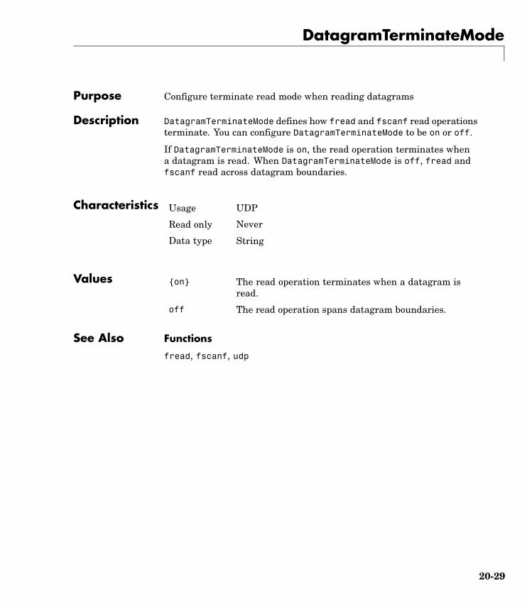
DatagramTerminateMode
Purpose Configure terminate read mode when reading datagrams
Description DatagramTerminateMode defines how fread and fscanf read operationsterminate. You can configure DatagramTerminateMode to be on or off.
If DatagramTerminateMode is on, the read operation terminates whena datagram is read. When DatagramTerminateMode is off, fread andfscanf read across datagram boundaries.
Characteristics Usage UDP
Read only Never
Data type String
Values {on} The read operation terminates when a datagram isread.
off The read operation spans datagram boundaries.
See Also Functions
fread, fscanf, udp
20-29

DataTerminalReady
Purpose Specify state of DTR pin
Description You can configure DataTerminalReady to be on or off. IfDataTerminalReady is on, the Data Terminal Ready (DTR) pin isasserted. If DataTerminalReady is off, the DTR pin is unasserted.
In normal usage, the DTR and Data Set Ready (DSR) pins worktogether, and are used to signal if instruments are connected andpowered. However, there is nothing in the RS-232 standard that statesthe DTR pin must be used in any specific way. For example, DTRand DSR might be used for handshaking. You should refer to yourinstrument documentation to determine its specific pin behavior.
You can return the value of the DSR pin with the PinStatus property.Handshaking is described in “The Control Pins” on page 6-7.
Characteristics Usage Serial port, VISA-serial
Read only Never
Data type String
Values {on} The DTR pin is asserted.
off The DTR pin is unasserted.
See Also Properties
FlowControl, PinStatus
20-30

DriverName
Purpose Specify name of driver used to communicate with instrument
Description For device objects with a DriverType property value of MATLABInstrument Driver, the DriverName property specifies the name of theMATLAB instrument driver that contains the supported instrumentcommands.
For device objects with a DriverType property value of VXIplug&play,IVI-C, or IVI-COM, the DriverName is the name of the VXIplug&play,IVI-C, or IVI-COM driver, respectively.
Characteristics Usage Device
Read only Always
Data type String
Values DriverName is defined at device object creation.
See Also Properties
DriverType
20-31

DriverSessions
Purpose Array of driver sessions contained in IVI configuration store
Description DriverSessions identifies all the driver sessions in the IVIconfiguration store. Each driver session maps a software module to ahardware asset and its IOResourceDescriptor. A driver session alsodetermines default settings and behavior for its software module.
Characteristics Usage IVI configuration store object
Read only Always
Data type Array of Structs
See Also Properties
HardwareAssets, SoftwareModules
20-32

DriverType
Purpose Specify type of driver used to communicate with instrument
Description DriverType can be MATLAB interface object, MATLAB VXIplug&play,or MATLAB IVI. If DriverType is MATLAB interface object, aninterface object is used to communicate with the instrument. IfDriverType is MATLAB VXIplug&play, a VXIplug&play driver is used tocommunicate with the instrument. If DriverType is MATLAB IVI, anIVI driver is used to communicate with the instrument.
Characteristics Usage Device
Read only Always
Data type String
Values The DriverType value is defined at the device object creation.DriverType can be MATLAB interface object, MATLAB VXIplug&play,or MATLAB IVI.
See Also Properties
DriverName
20-33

EOIMode
Purpose Specify if EOI line is asserted at end of write operation
Description You can configure EOIMode to be on or off. If EOIMode is on, the EndOr Identify (EOI) line is asserted at the end of a write operation. IfEOIMode is off, the EOI line is not asserted at the end of a writeoperation. EOIMode applies to both binary and text write operations.
Characteristics Usage GPIB, VISA-GPIB, VISA-VXI, VISA-GPIB-VXI
Read only Never
Data type String
Values {on} The EOI line is asserted at the end of a write operation.
off The EOI line is not asserted at the end of a writeoperation.
See Also Properties
BusManagementStatus
20-34

EOSCharCode
Purpose Specify EOS character
Description You can configure EOSCharCode to an integer value ranging from 0 to255, or to the equivalent ASCII character. For example, to configureEOSCharCode to a carriage return, you specify the value to be CR or 13.
EOSCharCode replaces \n wherever it appears in the ASCII commandsent to the instrument. Note that %s\n is the default format for thefprintf function.
For many practical applications, you will configure both EOSCharCodeand the EOSMode property. EOSMode specifies when the EOS character isused. If EOSMode is write or read&write (writing is enabled), the EOIline is asserted every time the EOSCharCode value is written to theinstrument. If EOSMode is read or read&write (reading is enabled),then the read operation might terminate when the EOSCharCode valueis detected. For GPIB objects, the CompareBits property specifies thenumber of bits that must match the EOS character to complete a reador write operation.
To see how EOSCharCode and EOSMode work together, refer to theexample given in the EOSMode property description.
Characteristics Usage GPIB, VISA-GPIB, VISA-VXI, VISA-GPIB-VXI
Read only Never
Data type ASCII value
Values An integer value ranging from 0 to 255 or the equivalent ASCIIcharacter. The default value is LF, which corresponds to a line feed.
See Also Functions
fprintf
Properties
CompareBits, EOSMode
20-35

EOSMode
Purpose Specify when EOS character is written or read
Description For GPIB, VISA-GPIB, VISA-VXI, and VISA-GPIB-VXI objects, you canconfigure EOSMode to be none, read, write, or read&write.
If EOSMode is none, the End-Of-String (EOS) character is ignored.If EOSMode is read, the EOS character is used to terminate a readoperation. If EOSMode is write, the EOS character is appended to theASCII command being written whenever \n is encountered. When theEOS character is written to the instrument, the End Or Identify (EOI)line is asserted. If EOSMode is read&write, the EOS character is used inboth read and write operations.
The EOS character is specified by the EOSCharCode property. For GPIBobjects, the CompareBits property specifies the number of bits thatmust match the EOS character to complete a read operation, or toassert the EOI line.
Rules for Completing a Read Operation
For any EOSMode value, the read operation completes when
• The EOI line is asserted.
• Specified number of values is read.
• A timeout occurs.
Additionally, if EOSMode is read or read&write (reading is enabled),then the read operation can complete when the EOSCharCode propertyvalue is detected.
Rules for Completing a Write Operation
Regardless of the EOSMode value, a write operation completes when
• The specified number of values is written.
• A timeout occurs.
20-36
EOSMode
Additionally, if EOSMode is write or read&write, the EOI line is assertedeach time the EOSCharCode property value is written to the instrument.
Characteristics Usage GPIB, VISA-GPIB, VISA-VXI, VISA-GPIB-VXI
Read only Never
Data type String
Values {none} The EOS character is ignored.
read The EOS character is used for each read operation.
write The EOS character is used for each write operation.
read&write The EOS character is used for each read and writeoperation.
Examples Suppose you input a nominal voltage signal of 2.0 volts into a functiongenerator, and read back the voltage value using fscanf.
g = gpib('ni',0,1);fopen(g)fprintf(g,'Volt?')out = fscanf(g)out =+2.00000E+00
The EOSMode and EOSCharCode properties are configured to terminatethe read operation when an E character is encountered.
set(g,'EOSMode','read')set(g,'EOSCharCode','E')fprintf(g,'Volt?')out = fscanf(g)out =+2.00000
20-37

EOSMode
See Also Properties
CompareBits, EOIMode, EOSCharCode
20-38

ErrorFcn
Purpose Specify M-file callback function to execute when error event occurs
Description You configure ErrorFcn to execute an M-file callback function when anerror event occurs.
Note An error event is generated only for asynchronous read and writeoperations.
An error event is generated when a timeout occurs. A timeout occurs ifa read or write operation does not successfully complete within the timespecified by the Timeout property. An error event is not generated forconfiguration errors such as setting an invalid property value.
If the RecordStatus property value is on, and an error event occurs, therecord file records this information:
• The event type as Error
• The error message
• The time the event occurred using the format day-month-yearhour:minute:second:millisecond
To learn how to create a callback function, refer to “Creating andExecuting Callback Functions” on page 4-32.
Characteristics Usage Any instrument object
Read only Never
Data type Callback function
Values The default value is an empty string.
20-39

ErrorFcn
See Also Functions
record
Properties
RecordStatus, Timeout
20-40
FlowControl
Purpose Specify data flow control method to use
Description You can configure FlowControl to be none, hardware, or software.If FlowControl is none, then data flow control (handshaking) is notused. If FlowControl is hardware, then hardware handshaking isused to control data flow. If FlowControl is software, then softwarehandshaking is used to control data flow.
Hardware handshaking typically utilizes the Request to Send (RTS) andClear to Send (CTS) pins to control data flow. Software handshakinguses control characters (Xon and Xoff) to control data flow. To learnmore about hardware and software handshaking, refer to “UsingControl Pins” on page 6-30.
You can return the value of the CTS pin with the PinStatus property.You can specify the value of the RTS pin with the RequestToSendproperty. However, if FlowControl is hardware, and you specify a valuefor RequestToSend, then that value might not be honored.
If you set the flowcontrol property to hardware and a hardwareconnection is not detected, the fwrite and the fprintf functions willreturn an error message.
Note Although you might be able to configure your instrument for bothhardware handshaking and software handshaking at the same time,the toolbox does not support this behavior.
Characteristics Usage Serial port, VISA-serial
Read only Never
Data type String
20-41

FlowControl
Values {none} No flow control is used.
hardware Hardware flow control is used.
software Software flow control is used.
See Also Properties
PinStatus, RequestToSend
20-42

HandshakeStatus
Purpose State of GPIB handshake lines
Description HandshakeStatus is a structure array that contains the fieldsDataValid, NotDataAccepted, and NotReadyForData. These fieldsindicate the state of the Data Valid (DAV), Not Data Accepted (NDAC)and Not Ready For Data (NRFD) GPIB lines, respectively.
HandshakeStatus can be on or off for any of these fields. A value ofon indicates the associated line is asserted. A value of off indicatesthe associated line is unasserted.
Characteristics Usage GPIB
Read only Never
Data type Structure
Values on The associated handshake line is asserted
off The associated handshake line is unasserted
The default value is instrument dependent.
20-43

HardwareAssets
Purpose Array of hardware assets contained in IVI configuration store
Description HardwareAssets specifies all hardware assets in the IVI configurationstore, each hardware asset referencing an IOResourceDescriptor.
Characteristics Usage IVI configuration store object
Read only Always
Data type Array of Structs
Values The default value is empty.
See Also Properties
DriverSessions, SoftwareModules
20-44

HwIndex
Purpose Hardware index of device group object
Description Every device group object contained by a device object has an associatedhardware index that is used to reference that device group object. Forexample, to configure property values for an individual device groupobject, you must reference the group object through its property nameand the appropriate HwIndex value.
HwIndex provides a convenient way to programmatically access devicegroup objects.
Characteristics Usage Device Group
Read only Always
Data type Double
Values The default value is defined at the device group object creation.
See Also Properties
HwName
20-45

HwName
Purpose Hardware name of device group object
Description Every device group object contained by a device object has an associatedhardware name that can be used to reference that device group object.
HwName provides a convenient way to programmatically access devicegroup objects.
Characteristics Usage Device Group
Read only Always
Data type String
Values The default value is defined at the device group object creation.
See Also Properties
HwIndex
20-46
InputBufferSize
Purpose Specify size of input buffer in bytes
Description You configure InputBufferSize as the total number of bytes that canbe stored in the software input buffer during a read operation.
A read operation is terminated if the amount of data stored in the inputbuffer equals the InputBufferSize value. You can read text data withthe fgetl, fgets, or fscanf functions. You can read binary data withthe fread function.
You can configure InputBufferSize only when the instrument object isdisconnected from the instrument. You disconnect an object with thefclose function. A disconnected object has a Status property value ofclosed.
If you configure InputBufferSize while there is data in the inputbuffer, then that data is flushed.
Characteristics Usage Any instrument object
Read only While open
Data type Double
Values The default value is 512.
See Also Functions
fclose, fgetl, fgets, fopen, fread, fscanf
Properties
Status
20-47

InstrumentModel
Purpose Instrument model that object connects to
Description InstrumentModel returns the information returned by the instrumentidentification command, e.g., *IDN?, *ID?. The instrument identificationcommand is defined by the instrument driver.
Characteristics Usage Device
Read only Always
Data type String
Values InstrumentModel will be an empty string until the object is connectedto the instrument with the connect function and the property valueis queried with the get function.
See Also Functions
connect, get
20-48

Interface
Purpose Interface object that communicates with instrument
Description If DriverType is MATLAB Instrument Driver, then Interface isthe interface object used to communicate with the instrument. IfDriverType is VXIplug&play or IVI-C, then Interface is the handleto the VISA session that is used to communicate with the instrument.If DriverType is IVI-COM, Interface is the handle to the IVI driver’sdefault interface.
Characteristics Usage Device
Read only Always
Data type String
Values Interface is defined at device object creation.
See Also Properties
DriverType, LogicalName, RsrcName
20-49

InterfaceIndex
Purpose Specify USB interface number
Description You configure InterfaceIndex to be the USB interface number.
The Name and RsrcName properties are automatically updated to reflectthe InterfaceIndex value.
You can configure InterfaceIndex only when the object is disconnectedfrom the instrument. You disconnect a connected object with the fclosefunction. A disconnected object has a Status property value of closed.
Characteristics Usage VISA-USB
Read only While open
Data type Double
See Also Functions
fclose
Properties
Name, RsrcName
20-50

InterruptFcn
Purpose Specify M-file callback function to execute when interrupt event occurs
Description You configure InterruptFcn to execute an M-file callback functionwhen an interrupt event occurs. An interrupt event is generated when aVXI bus signal or a VXI bus interrupt is received from the instrument.
Note An interrupt event can be generated at any time during theinstrument control session.
If the RecordStatus property value is on, and an interrupt event occurs,the record file records
• The event type as Interrupt
• The time the event occurred using the format day-month-yearhour:minute:second:millisecond
Characteristics Usage VISA-VXI
Read only Never
Data type String
Values The default value is an empty string.
See Also Functions
record
Properties
RecordStatus
20-51

LANName
Purpose Specify LAN device name
Description You configure LANName to be the LAN (Local Area Network) device name.
The Name and RsrcName properties are automatically updated to reflectthe LANName value.
You can configure LANName only when the object is disconnected fromthe instrument. You disconnect a connected object with the fclosefunction. A disconnected object has a Status property value of closed.
Characteristics Usage VISA-TCPIP
Read only While open
Data type String
See Also Functions
fclose
Properties
Name, RsrcName
20-52

LocalHost
Purpose Specify local host
Description LocalHost specifies the local host name or the IP dotted decimaladdress. An example dotted decimal address is 144.212.100.10. If youhave only one address or you do not specify this property, the objectuses the default IP address when you connect to the hardware withthe fopen function.
You can configure LocalHost only when the object is disconnectedfrom the hardware. You disconnect a connected object with the fclosefunction. A disconnected object has a Status property value of closed.
Characteristics Usage TCPIP, UDP
Read only While open
Data type String
Values The default value is an empty string.
See Also Functions
fclose, fopen, tcpip, udp
Properties
LocalPort, RemoteHost, Status
20-53

LocalPort
Purpose Specify local host port for connection
Description You configure LocalPort to be the port value of the local host. Thedefault value is [].
If LocalPortMode is set to auto or if LocalPort is [], the property isassigned any free port when you connect the object to the hardware withthe fopen function. If LocalPortMode is set to manual, the specifiedLocalPort value is used when you issue fopen. If you explicitlyconfigure LocalPort, LocalPortMode is automatically set to manual.
You can configure LocalPort only when the object is disconnectedfrom the hardware. You disconnect a connected object with the fclosefunction. A disconnected object has a Status property value of closed.
Characteristics Usage TCPIP, UDP
Read only While open
Data type Double
Values The default value is [].
See Also Functions
fclose, fopen, tcpip, udp
Properties
LocalHost, LocalPortMode, Status
20-54

LocalPortMode
Purpose Specify local host port selection mode
Description LocalPortMode specifies the selection mode for the LocalPort propertywhen you connect a TCPIP or UDP object.
If LocalPortMode is set to auto, MATLAB uses any free local port. IfLocalPortMode is set to manual, the specified LocalPort value is usedwhen you issue the fopen function. If you explicitly specify a value forLocalPort, LocalPortMode is automatically set to manual.
Characteristics Usage TCPIP, UDP
Read only While open
Data type String
Values {auto} Use any free local port.
manual Use the specified local port value.
See Also Functions
fclose, fopen, tcpip, udp
Properties
LocalHost, LocalPort, Status
20-55

LogicalAddress
Purpose Specify logical address of VXI instrument
Description For VISA-VXI and VISA-GPIB-VXI objects, you configureLogicalAddress to be the logical address of the VXI instrument. Youmust include the logical address as part of the resource name duringobject creation using the visa function.
The Name and RsrcName properties are automatically updated to reflectthe LogicalAddress value.
You can configure LogicalAddress only when the object is disconnectedfrom the instrument. You disconnect a connected object with the fclosefunction. A disconnected object has a Status property value of closed.
Characteristics Usage VISA-VXI, VISA-GPIB-VXI
Read only While open
Data type Double
Values The value is defined when the instrument object is created.
Examples This example creates a VISA-VXI object associated with chassis 4 andlogical address 1, and then returns the logical address.
vv = visa('agilent','VXI4::1::INSTR');vv.LogicalAddressans =
1
See Also Functions
fclose, visa
Properties
Name, RsrcName, Status
20-56

LogicalName
Purpose Specify description of interface used to communicate with instrument
Description For device objects with a DriverType property value of MATLABInstrument Driver, the LogicalName property specifies the type ofinterface used to communicate with the instrument. For example, aLogicalName of GPIB0-2 indicates that communication is through aGPIB board at index 0 with an instrument at primary address 2.
For device objects with a DriverType property value of VXIplug&play,the LogicalName is the resource name used to communicate with theinstrument.
For device objects with a DriverType property value of IVI-C orIVI-COM, the LogicalName is the LogicalName associated with theIVI-C or IVI-COM driver.
Characteristics Usage Device
Read only Always
Data type String
Values LogicalName is defined at device object creation.
See Also Properties
DriverType, Interface, RsrcName
20-57

LogicalNames
Purpose Array of logical names contained in IVI configuration store
Description Each entry in LogicalNames identifies a logical name in the IVIconfiguration store. Each logical name references a driver session inthe configuration store, and is used in creating device objects with theicdevice function.
Characteristics Usage IVI configuration store object
Read only Always
Data type Array of Structs
See Also Functions
icdevice
Properties
DriverSessions
20-58

ManufacturerID
Purpose Specify manufacturer ID of USB instrument
Description You configure ManufacturerID to be the manufacturer ID of the USBinstrument.
The Name and RsrcName properties are automatically updated to reflectthe ManufacturerID value.
You can configure ManufacturerID only when the object is disconnectedfrom the instrument. You disconnect a connected object with the fclosefunction. A disconnected object has a Status property value of closed.
Characteristics Usage VISA-USB
Read only While open
Data type String
See Also Functions
fclose
Properties
Name, RsrcName
20-59

MappedMemoryBase
Purpose Base memory address of mapped memory
Description MappedMemoryBase is the base address of the mapped memory used forlow level read and write operations.
The memory address is returned as a string representing a hexadecimalvalue. For example, if the mapped memory base is 200000, thenMappedMemoryBase returns 200000H. If no memory is mapped,MappedMemoryBase is 0H.
Use the memmap function to map the specified amount of memory in thespecified address space (A16, A24, or A32) with the specified offset. Usethe memunmap function to unmap the memory space.
Characteristics Usage VISA-VXI, VISA-GPIB-VXI
Read only Always
Data type String
Values The default value is 0H.
Examples Create the VISA-VXI object vv associated with a VXI chassis with index0, and an Agilent E1432A digitizer with logical address 130.
vv = visa('agilent','VXI0::130::INSTR');fopen(vv)
Map 16 bytes in the A16 address space with no offset, and then returnthe base address of the mapped memory.
memmap(vv,'A16',0,16)vv.MappedMemoryBaseans =
16737610H
20-60

MappedMemoryBase
See Also Functions
memmap, memunmap
Properties
MappedMemorySize
20-61

MappedMemorySize
Purpose Size of mapped memory for low-level read and write operations
Description MappedMemorySize indicates the amount of memory mapped forlow-level read and write operations.
Use the memmap function to map the specified amount of memory in thespecified address space (A16, A24, or A32) with the specified offset. Usethe memunmap function to unmap the memory space.
Characteristics Usage VISA-VXI, VISA-GPIB-VXI
Read only Always
Data type Double
Values The default value is 0.
Examples Create the VISA-VXI object vv associated with a VXI chassis with index0, and an Agilent E1432A digitizer with logical address 130.
vv = visa('agilent','VXI0::130::INSTR');fopen(vv)
Map 16 bytes in the A16 address space with no offset, and then returnthe size of the mapped memory.
memmap(vv,'A16',0,16)vv.MappedMemorySizeans =
16
See Also Functions
memmap, memunmap
Properties
MappedMemoryBase
20-62

MasterLocation
Purpose Full pathname of master configuration store file
Description MasterLocation identifies the master (default) configuration storelocation.
Characteristics Usage IVI configuration store object
Read only Always
Data type String
Values The default value is set at IVI installation.
See Also Properties
ActualLocation, ProcessLocation
20-63

MemoryBase
Purpose Base address of A24 or A32 space
Description MemoryBase indicates the base address of the A24 or A32 space. Thevalue is returned as a string representing a hexadecimal value.
All VXI instruments have an A16 address space that is 16 bits wide.There are also 24- and 32-bit wide address spaces known as A24 andA32. Some instruments require the additional memory associatedwith the A24 or A32 address space when the 64 bytes of A16 spaceare insufficient for performing necessary functions. A bit in the A16address space is set allowing the instrument to recognize commands toits A24 or A32 space.
An instrument cannot use both the A24 and A32 address space. Theaddress space is given by the MemorySpace property. If MemorySpace isA16, then MemoryBase is 0H.
Characteristics Usage VISA-VXI, VISA-GPIB-VXI
Read only Always
Data type String
Values The default value is 0H.
Examples Create the VISA-VXI object vv associated with a VXI chassis with index0, and an Agilent E1432A digitizer with logical address 130.
vv = visa('agilent','VXI0::130::INSTR');fopen(vv)
The MemorySpace property indicates that the A24 memory space issupported.
vv.MemorySpaceans =A16/A24
20-64

MemoryBase
The base address of the A24 space is
vv.MemoryBaseans ='200000H'
See Also Properties
MemorySpace
20-65

MemoryIncrement
Purpose Specify whether VXI register offset increments after data is transferred
Description You can configure MemoryIncrement to be block or FIFO. IfMemoryIncrement is block, the memread and memwrite functionsincrement the offset after every read and write operation, anddata is transferred from or to consecutive memory elements. IfMemoryIncrement is FIFO, the memread and memwrite functions do notincrement the VXI register offset, and data is always read from orwritten to the same memory element.
Characteristics Usage VISA-VXI, VISA-GPIB-VXI
Read only Never
Data type String
Values {block} Increment the VXI register offset.
FIFO Do not increment the VXI register offset.
Examples Create the VISA-VXI object v associated with a VXI chassis with index0, and an instrument with logical address 8.
v = visa('ni','VXI0::8::INSTR');fopen(v)
Configure the hardware for a FIFO read and write operation.
set(v,'MemoryIncrement','FIFO')
Write two values to the VXI register starting at offset 16. BecauseMemoryIncrement is FIFO, the VXI register offset does not change andboth values are written to offset 16.
memwrite(v,[1984 2000],16,'uint32','A16')
20-66

MemoryIncrement
Read the value at offset 16. The value returned is the second valuewritten with the memwrite function.
memread(v,16,'uint32')ans =2000
Read two values starting at offset 16. Note that both values are readat offset 16.
memread(v,16,'uint32','A16',2);ans =20002000
Configure the hardware for a block read and write operation.
set(v,'MemoryIncrement','block')
Write two values to the VXI register starting at offset 16. The firstvalue is written to offset 16 and the second value is written to offset 20because a uint32 value consists of four bytes.
memwrite(v,[1984 2000],16,'uint32','A16')
Read the value at offset 16. The value returned is the first value writtenwith the memwrite function.
memread(v,16,'uint32')ans =1984
Read two values starting at offset 16. The first value is read at offset16 and the second value is read at offset 20.
memread(v,16,'uint32','A16',2);ans =19842000
20-67

MemoryIncrement
See Also Functions
mempeek, mempoke, memread, memwrite
20-68

MemorySize
Purpose Size of memory requested in A24 or A32 address space
Description MemorySize indicates the size of the memory requested by theinstrument in the A24 or A32 address space.
Some instruments use the A24 or A32 address space when the 64bytes of A16 space are not enough for performing necessary functions.An instrument cannot use both the A24 and A32 address space. Theaddress space is given by the MemorySpace property. If MemorySpace isA16, then MemorySize is 0.
Characteristics Usage VISA-VXI, VISA-GPIB-VXI
Read only Always
Data type Double
Values The default value is 0.
Examples Create the VISA-VXI object vv associated with a VXI chassis with index0, and an Agilent E1432A digitizer with logical address 130.
vv = visa('agilent','VXI0::130::INSTR');fopen(vv)
The MemorySpace property indicates that the A24 memory space issupported.
vv.MemorySpaceans =A16/A24
The size of the A24 space is
vv.MemorySizeans =262144
20-69

MemorySize
See Also Properties
MemorySpace
20-70

MemorySpace
Purpose Address space used by instrument
Description MemorySpace indicates the address space requested by the instrument.MemorySpace can be A16, A16/A24, or A16/A32. If MemorySpace isA16, the instrument uses only the A16 address space. If MemorySpaceis A16/A24, the instrument uses the A16 and A24 address space. IfMemorySpace is A16/A32, the instrument uses the A16 and A32 addressspace.
All VXI instruments have an A16 address space that is 16 bits wide.There are also 24- and 32-bit wide address spaces known as A24 andA32, respectively. Some instruments use this memory when the 64bytes of A16 space are not enough for performing necessary functions.An instrument cannot use both the A24 and A32 address space.
The size of the memory is given by the MemorySize property. The baseaddress of the memory is given by the MemoryBase property.
Characteristics Usage VISA-VXI, VISA-GPIB-VXI
Read only Always
Data type String
Values {A16} The instrument uses the A16 address space.
A16/A24 The instrument uses the A16 and A24 address space.
A16/A32 The instrument uses the A16 and A32 address space.
Examples Create the VISA-VXI object vv associated with a VXI chassis with index0, and an Agilent E1432A digitizer with logical address 130.
vv = visa('agilent','VXI0::130::INSTR');fopen(vv)
20-71

MemorySpace
Return the memory space supported by the instrument.
vv.MemorySpaceans =A16/A24
This value indicates that the instrument supports A24 memory space inaddition to the A16 memory space.
See Also Properties
MemoryBase, MemorySize
20-72
ModelCode
Purpose Specify model code of USB instrument
Description You configure ModelCode to be the model code of the USB instrument.
The Name and RsrcName properties are automatically updated to reflectthe ModelCode value.
You can configure ModelCode only when the object is disconnected fromthe instrument. You disconnect a connected object with the fclosefunction. A disconnected object has a Status property value of closed.
Characteristics Usage VISA-USB
Read only While open
Data type String
See Also Functions
fclose
Properties
Name, RsrcName
20-73

Name
Purpose Specify descriptive name for instrument object
Description You configure Name to be a descriptive name for an instrument object.
When you create an instrument object, a descriptive name isautomatically generated and stored in Name. However, you can changethis value at any time. As shown below, the components of Name reflectthe instrument object type and the input arguments you supply to thecreation function.
InstrumentObject Default Value of Name
GPIB GPIB andBoardIndex-PrimaryAddress-SecondaryAddress
serial port Serial and Port
TCPIP TCPIP and RemoteHost
UDP UDP and RemoteHost
VISA-serial VISA-Serial and Port
VISA-GPIB VISA-GPIB andBoardIndex-PrimaryAddress-SecondaryAddress
VISA-VXI VISA-VXI and ChassisIndex-LogicalAddress
VISA-GPIB-VXI VISA-GPIB-VXI andChassisIndex-LogicalAddress
VISA-TCPIP VISA-TCPIP and BoardIndex-RemoteHost-LANName
VISA-RSIB VISA-RSIB and RemoteHost
VISA-USB VISA-USB and BoardIndex-ManufacturerID-ModelCode-SerialNumber-InterfaceIndex
If the secondary address is not specified when a GPIB or VISA-GPIBobject is created, then Name does not include this component.
20-74

Name
If you change the value of any property that is a component of Name(for example, Port or PrimaryAddress), then Name is automaticallyupdated to reflect those changes.
Characteristics Usage Any instrument object
Read-only Never
Data type String
Values Name is automatically defined at object creation time. The value of Namedepends on the specific instrument object you create.
20-75

Name (iviconfigurationstore)
Purpose Name of IVI configuration server
Description Name identifies the name of the IVI configuration store server. This isnot user-configurable.
Characteristics Usage IVI configuration store object
Read only Always
Data type String
20-76

ObjectVisibility
Purpose Control access to instrument object
Description The ObjectVisibility property provides a way for applicationdevelopers to prevent end-user access to the instrument objects createdby their application. When an object’s ObjectVisibility property is setto off, instrfind and instrreset do not return or delete those objects.
Objects that are not visible are still valid. If you have access to theobject (for example, from within the M-file that creates it), then you canset and get its properties and pass it to any function that operates oninstrument objects.
Characteristics Usage Any instrument object
Read only Never
Data type String
Values The default value is on.
{on} Object is visible to instrfind and instrreset
off Object is not visible from the command line (except byinstrfindall)
Examples The following statement creates an instrument object with itsObjectVisibility property set to off:
g = gpib('keithley',0,2,'ObjectVisibility','off');instrfindans =
[]
However, since the object is in the workspace (g), you can access it.
get(g,'ObjectVisibility')ans =
20-77

ObjectVisibility
off
See Also Functions
instrfind, instrfindall, instrreset
20-78

OutputBufferSize
Purpose Specify size of output buffer in bytes
Description You configure OutputBufferSize as the total number of bytes that canbe stored in the software output buffer during a write operation.
An error occurs if the output buffer cannot hold all the data to bewritten. You write text data with the fprintf function. You writebinary data with the fwrite function.
You can configure OutputBufferSize only when the instrument objectis disconnected from the instrument. You disconnect an object with thefclose function. A disconnected object has a Status property value ofclosed.
Characteristics Usage Any instrument object
Read only While open
Data type Double
Values The default value is 512.
See Also Functions
fprintf, fwrite
Properties
Status
20-79

OutputEmptyFcn
Purpose Specify M-file callback function to execute when output buffer is empty
Description You configure OutputEmptyFcn to execute an M-file callback functionwhen an output-empty event occurs. An output-empty event isgenerated when the last byte is sent from the output buffer to theinstrument.
Note An output-empty event can be generated only for asynchronouswrite operations.
If the RecordStatus property value is on, and an output-empty eventoccurs, the record file records this information:
• The event type as OutputEmpty
• The time the event occurred using the format day-month-yearhour:minute:second:millisecond
To learn how to create a callback function, refer to “Creating andExecuting Callback Functions” on page 4-32.
Characteristics Usage Any instrument object
Readonly
Never
Data type Callback function
Values The default value is an empty string.
See Also Functions
record
20-80

OutputEmptyFcn
Properties
RecordStatus
20-81

Parent
Purpose Parent (device object) of device group object
Description The parent of a device group object is defined as the device object thatcontains the device group object.
You can create a copy of the device object containing a particular devicegroup object by returning the value of Parent. This copy can be treatedlike any other device object. For example, you can configure propertyvalues, connect to the instrument, and so on.
Characteristics Usage Device group
Read only Always
Data type Device object
Values Parent is defined at device object creation.
20-82

Parity
Purpose Specify type of parity checking
Description You can configure Parity to be none, odd, even, mark, or space. IfParity is none, parity checking is not performed and the parity bit isnot transmitted. If Parity is odd, the number of mark bits (1s) in thedata is counted, and the parity bit is asserted or unasserted to obtain anodd number of mark bits. If Parity is even, the number of mark bitsin the data is counted, and the parity bit is asserted or unasserted toobtain an even number of mark bits. If Parity is mark, the parity bit isasserted. If Parity is space, the parity bit is unasserted.
Parity checking can detect errors of one bit only. An error in two bitsmight cause the data to have a seemingly valid parity, when in fact itis incorrect. To learn more about parity checking, refer to “The ParityBit” on page 6-12.
In addition to the parity bit, the serial data format consists of a startbit, between five and eight data bits, and one or two stop bits. Youspecify the number of data bits with the DataBits property, and thenumber of stop bits with the StopBits property.
Characteristics Usage Serial port, VISA-serial
Read only Never
Data type String
Values {none} No parity checking
odd Odd parity checking
even Even parity checking
mark Mark parity checking
space Space parity checking
20-83

Parity
See Also Properties
DataBits, StopBits
20-84

PinStatus
Purpose State of CD, CTS, DSR, and RI pins
Description PinStatus is a structure array that contains the fields CarrierDetect,ClearToSend, DataSetReady and RingIndicator. These fields indicatethe state of the Carrier Detect (CD), Clear to Send (CTS), Data SetReady (DSR) and Ring Indicator (RI) pins, respectively. Refer to “TheControl Pins” on page 6-7 to learn more about these pins.
PinStatus can be on or off for any of these fields. A value of onindicates the associated pin is asserted. A value of off indicates theassociated pin is unasserted. For serial port objects, a pin status eventoccurs when any of these pins changes its state. A pin status eventexecutes the M-file specified by PinStatusFcn.
In normal usage, the Data Terminal Ready (DTR) and DSR pinswork together, while the Request To Send (RTS) and CTS pinswork together. You can specify the state of the DTR pin with theDataTerminalReady property. You can specify the state of the RTS pinwith the RequestToSend property.
Refer to “Example: Connecting Two Modems” on page 6-31 for anexample that uses PinStatus.
Characteristics Usage Serial port, VISA-serial
Read only Always
Data type Structure
Values off The associated pin is asserted
on The associated pin is asserted
The default value is instrument dependent.
20-85

PinStatus
See Also Properties
DataTerminalReady, PinStatusFcn, RequestToSend
20-86

PinStatusFcn
Purpose Specify M-file callback function to execute when CD, CTS, DSR, or RIpin changes state
Description You configure PinStatusFcn to execute an M-file callback functionwhen a pin status event occurs. A pin status event occurs when theCarrier Detect (CD), Clear to Send (CTS), Data Set Ready (DSR) orRing Indicator (RI) pin changes state. A serial port pin changes statewhen it is asserted or unasserted. Information about the state of thesepins is recorded in the PinStatus property.
Note A pin status event can be generated at any time during theinstrument control session.
If the RecordStatus property value is on, and a pin status event occurs,the record file records this information:
• The event type as PinStatus
• The pin that changed its state, and pin state as either on or off
• The time the event occurred using the format day-month-yearhour:minute:second:millisecond
To learn how to create a callback function, refer to “Creating andExecuting Callback Functions” on page 4-32.
Characteristics Usage Serial port
Read only Never
Data type Callback function
Values The default value is an empty string.
20-87

PinStatusFcn
See Also Functions
record
Properties
PinStatus, RecordStatus
20-88

Port
Purpose Specify platform-specific serial port name
Description You configure Port to be the name of a serial port on your platform.Port specifies the physical port associated with the object and theinstrument.
When you create a serial port or VISA-serial object, Port isautomatically assigned the port name specified for the serial or visafunction.
You can configure Port only when the object is disconnected from theinstrument. You disconnect an object with the fclose function. Adisconnected object has a Status property value of closed.
Characteristics Usage Serial port, VISA-serial
Read only While open
Data type String
Values The value is determined when the instrument object is created.
Examples Suppose you create a serial port and VISA-serial object associated withserial port COM1.
s = serial('COM1')vs = visa('ni','ASRL1::INSTR')
The Port property values are given below.
get([s vs],'Port')ans =
'COM1''ASRL1'
See Also Functions
fclose, serial, visa
20-89

Port
Properties
Name, RsrcName, Status
20-90

PrimaryAddress
Purpose Specify primary address of GPIB instrument
Description For GPIB and VISA-GPIB objects, you configure PrimaryAddress tobe the GPIB primary address associated with your instrument. Theprimary address can range from 0 to 30, and you must specify it duringobject creation using the gpib or visa function. For VISA-GPIB-VXIobjects, PrimaryAddress is read-only, and the value is returnedautomatically by the VISA interface after the object is connected to theinstrument with the fopen function.
For GPIB and VISA-GPIB objects, the Name property is automaticallyupdated to reflect the PrimaryAddress value. For VISA-GPIBobjects, the RsrcName property is automatically updated to reflect thePrimaryAddress value.
You can configure PrimaryAddress only when the GPIB or VISA-GPIBobject is disconnected from the instrument. You disconnect a connectedobject with the fclose function. A disconnected object has a Statusproperty value of closed.
Characteristics Usage GPIB, VISA-GPIB, VISA-GPIB-VXI
Read only While open (GPIB, VISA-GPIB), always(VISA-GPIB-VXI)
Data type Double
Values PrimaryAddress can range from 0 to 30. The value is determined whenthe instrument object is created.
20-91

PrimaryAddress
Examples This example creates a VISA-GPIB object associated with board 0,primary address 1, and secondary address 8, and then returns theprimary address.
vg = visa('agilent','GPIB0::1::8::INSTR');vg.PrimaryAddressans =
1
See Also Functions
fclose, gpib, visa
Properties
Name, RsrcName, Status
20-92

ProcessLocation
Purpose Configuration store file for process to use if master configuration storeis not used
Description ProcessLocation identifies an IVI configuration store being used as analternative to the master configuration store. The use of an alternativeis particular to each iviconfigurationstore object, and is specifiedwhen the object is created.
Characteristics Usage IVI configuration store object
Read only Always
Data type String
Values The default value is an empty string.
See Also Functions
iviconfigurationstore
Properties
ActualLocation, MasterLocation
20-93

PublishedAPIs
Purpose Array of published APIs in IVI configuration store
Description PublishedAPIs identifies the published APIs in the IVI configurationstore server. This is not user-configurable.
Characteristics Usage IVI configuration store object
Read only Always
Data type Array of Structs
20-94

ReadAsyncMode
Purpose Specify whether asynchronous read operation is continuous or manual
Description You can configure ReadAsyncMode to be continuous or manual. IfReadAsyncMode is continuous, the object continuously queries theinstrument to determine if data is available to be read. If data isavailable, it is automatically read and stored in the input buffer. Ifissued, the readasync function is ignored.
If ReadAsyncMode is manual, the object will not query the instrument todetermine if data is available to be read. Instead, you must manuallyissue the readasync function to perform an asynchronous readoperation. Because readasync checks for the terminator, this functioncan be slow. To increase speed, you should configure ReadAsyncModeto continuous.
Note If the instrument is ready to transmit data, then it will do soregardless of the ReadAsyncMode value. Therefore, if ReadAsyncMode ismanual and a read operation is not in progress, then data can be lost. Toguarantee that all transmitted data is stored in the input buffer, youshould configure ReadAsyncMode to continuous.
You can determine the amount of data available in the input buffer withthe BytesAvailable property. For either ReadAsyncMode value, you canbring data into the MATLAB workspace with one of the synchronousread functions such as fscanf, fgetl, fgets, or fread.
Characteristics Usage Serial port, TCPIP, UDP, VISA-serial
Read only Never
Data type String
20-95

ReadAsyncMode
Values {continuous} Continuously query the instrument to determine ifdata is available to be read.
manual Manually read data from the instrument using thereadasync function.
See Also Functions
fgetl, fgets, fread, fscanf, readasync
Properties
BytesAvailable, InputBufferSize
20-96

RecordDetail
Purpose Specify amount of information saved to record file
Description You can configure RecordDetail to be compact or verbose. IfRecordDetail is compact, the number of values written to theinstrument, the number of values read from the instrument, the datatype of the values, and event information are saved to the record file.If RecordDetail is verbose, the data transferred to and from theinstrument is also saved to the record file.
The verbose record file structure is shown in “Example: RecordingInformation to Disk” on page 12-10.
Characteristics Usage Any instrument object
Read only Never
Data type String
Values {compact} The number of values written to the instrument, thenumber of values read from the instrument, the datatype of the values, and event information are saved tothe record file.
verbose The data written to the instrument, and the data readfrom the instrument are also saved to the record file.
See Also Functions
record
Properties
RecordMode, RecordName, RecordStatus
20-97

RecordMode
Purpose Specify whether data and event information are saved to one or tomultiple record files
Description You can configure RecordMode to be overwrite, append, or index. IfRecordMode is overwrite, then the record file is overwritten each timerecording is initiated. If RecordMode is append, then data is appendedto the record file each time recording is initiated. If RecordMode isindex, a different record file is created each time recording is initiated,each with an indexed filename.
You can configure RecordMode only when the object is not recording.You terminate recording with the record function. A object that is notrecording has a RecordStatus property value of off.
You specify the record filename with the RecordName property. Theindexed filename follows a prescribed set of rules. Refer to “Specifying aFile Name” on page 12-8 for a description of these rules.
Characteristics Usage Any instrument object
Read only While recording
Data type String
Values {overwrite} The record file is overwritten.
append Data is appended to the record file.
index Multiple record files are written, each with an indexedfilename.
Examples Suppose you create the serial port object s associated with the serialport COM1.
s = serial('COM1');fopen(s)
20-98

RecordMode
Specify the record filename with the RecordName property, configureRecordMode to index, and initiate recording.
s.RecordName = 'myrecord.txt';s.RecordMode = 'index';record(s)
The record filename is automatically updated with an indexed filenameafter recording is turned off.
record(s,'off')s.RecordNameans =myrecord01.txt
Disconnect s from the instrument, and remove s from memory and fromthe MATLAB workspace.
fclose(s)delete(s)clear s
See Also Functions
record
Properties
RecordDetail, RecordName, RecordStatus
20-99

RecordName
Purpose Specify name of record file
Description You configure RecordName to be the name of the record file. You canspecify any value for RecordName — including a directory path —provided the filename is supported by your operating system.
MATLAB supports any filename supported by your operating system.However, if you access the file through MATLAB, you might need tospecify the filename using single quotes. For example, suppose youname the record file my record.txt. To type this file at the MATLABcommand line, you must include the name in quotes.
type('my record.txt')
You can specify whether data and event information are saved to onedisk file or to multiple disk files with the RecordMode property. IfRecordMode is index, then the filename follows a prescribed set ofrules. Refer to “Specifying a File Name” on page 12-8 for a descriptionof these rules.
You can configure RecordName only when the object is not recording.You terminate recording with the record function. An object that is notrecording has a RecordStatus property value of off.
Characteristics Usage Any instrument object
Read only While recording
Data type String
Values The default record file name is record.txt.
See Also Functions
record
Properties
RecordDetail, RecordMode, RecordStatus
20-100

RecordStatus
Purpose Status of whether data and event information are saved to record file
Description You can configure RecordStatus to be off or on with the recordfunction. If RecordStatus is off, then data and event information arenot saved to a record file. If RecordStatus is on, then data and eventinformation are saved to the record file specified by RecordName.
Use the record function to initiate or complete recording. RecordStatusis automatically configured to reflect the recording state.
Characteristics Usage Any instrument object
Read only Always
Data type String
Values {off} Data and event information are not written to a recordfile
on Data and event information are written to a record file
See Also Functions
record
Properties
RecordDetail, RecordMode, RecordName
20-101

RemoteHost
Purpose Specify remote host
Description RemoteHost specifies the remote host name or IP dotted decimaladdress. An example dotted decimal address is 144.212.100.10.
For TCPIP objects, you can configure RemoteHost only when the objectis disconnected from the hardware. You disconnect a connected objectwith the fclose function. A disconnected object has a Status propertyvalue of closed.
For UDP objects, you can configure RemoteHost at any time. If theobject is open, a warning is issued if the remote address is invalid.
Characteristics Usage TCPIP, UDP
Read only While open (TCPIP), never (UDP)
Data type String
Values The value is defined when you create the TCPIP or UDP object.
See Also Functions
fclose, fopen, tcpip, udp
Properties
LocalHost, RemotePort, Status
20-102

RemotePort
Purpose Specify remote host port for connection
Description You can configure RemotePort to be any port number between 1 and65535. The default value is 80 for TCPIP objects and 9090 for UDPobjects.
For TCPIP objects, you can configure RemotePort only when the objectis disconnected from the hardware. You disconnect a connected objectwith the fclose function. A disconnected object has a Status propertyvalue of closed.
For UDP objects, you can configure RemotePort at any time.
Characteristics Usage TCPIP, UDP
Read only While open (TCPIP), never (UDP)
Data type Double
Values Any port number between 1 and 65535. The default value is 80 forTCPIP objects and 9090 for UDP objects.
See Also Functions
fclose, fopen, tcpip, udp
Properties
RemoteHost, LocalPort, Status
20-103

RequestToSend
Purpose Specify state of RTS pin
Description You can configure RequestToSend to be on or off. If RequestToSendis on, the Request to Send (RTS) pin is asserted. If RequestToSend isoff, the RTS pin is unasserted.
In normal usage, the RTS and Clear to Send (CTS) pins work together,and are used as standard handshaking pins for data transfer. In thiscase, RTS and CTS are automatically managed by the DTE and DCE.However, there is nothing in the RS-232 standard that states the RTSpin must to be used in any specific way. Therefore, if you manuallyconfigure the RequestToSend value, it is probably for nonstandardoperations.
If your instrument does not use hardware handshaking in the standardway, and you need to manually configure RequestToSend, then youshould configure the FlowControl property to none. Otherwise, theRequestToSend value that you specify might not be honored. Refer toyour instrument documentation to determine its specific pin behavior.
You can return the value of the CTS pin with the PinStatus property.Handshaking is described in “The Control Pins” on page 6-7.
Characteristics Usage Serial port, VISA-serial
Read only Never
Data type String
Values {on} The RTS pin is asserted.
off The RTS pin is unasserted.
See Also Properties
FlowControl, PinStatus
20-104

Revision
Purpose IVI configuration store version
Description Revision identifies the version of the IVI configuration store. This isnot user-configurable.
Characteristics Usage IVI configuration store object
Read only Always
Data type String
20-105

RsrcName
Purpose Resource name for VISA instrument
Description RsrcName indicates the resource name for a VISA instrument. Whenyou create a VISA object, RsrcName is automatically assigned the valuespecified in the visa function.
The resource name is a symbolic name for the instrument. The resourcename you supply to visa depends on the interface and has the formatshown below. The components in brackets are optional and have adefault value of 0, except port_number, which has a default value of 1.
Interface Resource Name
VXI VXI[chassis]::VXI_logical_address::INSTR
GPIB-VXI GPIB-VXI[chassis]::VXI_logical_address::INSTR
GPIB GPIB[board]::primary_address[::secondary_address]::INSTR
TCPIP TCPIP[board]::remote_host[::lan_device_name]::INSTR
RSIB RSIB::remote_host::INSTR
Serial ASRL[port_number]::INSTR
USB USB[board]::manid::model_code::serial_No[::interface_No]::INSTR
If you change the BoardIndex, ChassisIndex, InterfaceIndex,LANName, LogicalAddress, ManufacturerID, ModelCode, Port,PrimaryAddress, RemoteHost, SecondaryAddress, or SerialNumberproperty value, RsrcName is automatically updated to reflect the change.
Characteristics Usage VISA-GPIB, VISA-VXI, VISA-GPIB-VXI, VISA-serial
Read only Always
Data type String
Values The value is defined when the instrument object is created.
20-106

RsrcName
Examples To create a VISA-GPIB object associated with a GPIB controller withboard index 0 and an instrument with primary address 1, you supplythe following resource name to the visa function.
vg = visa('ni','GPIB0::1::INSTR');
To create a VISA-VXI object associated with a VXI chassis with index 0and an instrument with logical address 130, you supply the followingresource name to the visa function.
vv = visa('agilent','VXI0::130::INSTR');
To create a VISA-GPIB-VXI object associated with a VXI chassis withindex 0 and an instrument with logical address 80, you supply thefollowing resource name to the visa function.
vgv = visa('agilent','GPIB-VXI0::80::INSTR');
To create a VISA-serial object associated with the COM1 serial port, yousupply the following resource name to the visa function.
vs = visa('ni','ASRL1::INSTR');
See Also Functions
visa
Properties
BoardIndex, ChassisIndex, InterfaceIndex, LANName,LogicalAddress, ManufacturerID, ModelCode, Port, PrimaryAddress,RemoteHost, SecondaryAddress, SerialNumber
20-107

SecondaryAddress
Purpose Specify secondary address of GPIB instrument
Description For GPIB and VISA-GPIB objects, you configure SecondaryAddressto be the GPIB secondary address associated with your instrument.You can initially specify the secondary address during object creationusing the gpib or visa function. For VISA-GPIB-VXI objects,SecondaryAddress is read-only, and the value is returned automaticallyby the VISA interface after the object is connected to the instrumentwith the fopen function.
For GPIB objects, SecondaryAddress can range from 96 to 126, or itcan be 0 indicating that no secondary address is used. For VISA-GPIBobjects, SecondaryAddress can range from 0 to 30. If your instrumentdoes not have a secondary address, then SecondaryAddress is 0.
For GPIB and VISA-GPIB objects, the Name property is automaticallyupdated to reflect the SecondaryAddress value. For VISA-GPIBobjects, the RsrcName property is automatically updated to reflect theSecondaryAddress value.
You can configure SecondaryAddress only when the GPIB orVISA-GPIB object is disconnected from the instrument. You disconnecta connected object with the fclose function. A disconnected object hasa Status property value of closed.
Characteristics Usage GPIB, VISA-GPIB, VISA-GPIB-VXI
Read only While open (GPIB, VISA-GPIB), always(VISA-GPIB-VXI)
Data type Double
Values For GPIB objects, SecondaryAddress can range from 96 to 126, or it canbe 0. For VISA-GPIB objects, SecondaryAddress can range from 0 to30. The default value is 0.
20-108

SecondaryAddress
Examples This example creates a VISA-GPIB object associated with board 0,primary address 1, and secondary address 8, and then returns thesecondary address.
vg = visa('agilent','GPIB0::1::8::INSTR');vg.SecondaryAddressans =
8
See Also Functions
fclose, gpib, visa
Properties
Name, RsrcName, Status
20-109

SerialNumber
Purpose Specify index of USB instrument on USB hub
Description You configure SerialNumber to be the index of the USB instrumenton the USB hub.
The Name and RsrcName properties are automatically updated to reflectthe SerialNumber value.
You can configure SerialNumber only when the object is disconnectedfrom the instrument. You disconnect a connected object with the fclosefunction. A disconnected object has a Status property value of closed.
Characteristics Usage VISA-USB
Read only While open
Data type String
See Also Functions
fclose
Properties
Name, RsrcName
20-110

ServerDescription
Purpose IVI configuration store server description
Description ServerDescription contains the description of the IVI configurationstore server. This is not user-configurable.
Characteristics Usage IVI configuration store object
Read only Always
Data type String
20-111

Sessions
Purpose Array of driver sessions in IVI configuration store
Description Sessions identifies the sessions in the IVI configuration store, includingthe driver sessions.
Characteristics Usage IVI configuration store object
Read only Always
Data type Array of Structs
See Also Properties
DriverSessions
20-112

Slot
Purpose Slot location of VXI instrument
Description Slot indicates the physical slot of the VXI instrument. Slot can beany value between 0 and 12.
Characteristics Usage VISA-VXI, VISA-GPIB-VXI
Read only Always
Data type Double
Values The property value is defined when the instrument object is connected.
20-113

SoftwareModules
Purpose Array of software modules in IVI configuration store
Description SoftwareModules identifies the software modules in the IVIconfiguration store. These are installed by the user, but are notconfigurable. They include instrument drivers.
Characteristics Usage IVI configuration store object
Read only Always
Data type Array of Structs
Values The default value is empty when no software modules are installed.
See Also Properties
DriverSessions, HardwareAssets
20-114

SpecificationVersion
Purpose IVI configuration server specification version that this server revisioncomplies with
Description SpecificationVersion identifies the specification version of the IVIconfiguration store server. This is not user-configurable.
Characteristics Usage IVI configuration store object
Read only Always
Data type String
20-115

Status
Purpose Status of whether object is connected to instrument
Description Status can be open or closed. If Status is closed, the object is notconnected to the instrument. If Status is open, the object is connectedto the instrument.
Before you can write or read data, you must connect the object to theinstrument with the fopen function. You use the fclose function todisconnect an object from the instrument.
Characteristics Usage Any instrument object
Read only Always
Data type String
Values {closed} The object is not connected to the instrument.
open The object is connected to the instrument.
See Also Functions
fclose, fopen
20-116

StopBits
Purpose Specify number of bits used to indicate end of byte
Description You can configure StopBits to be 1, 1.5, or 2 for serial port objects, or1 or 2 for VISA-serial objects If StopBits is 1, one stop bit is used toindicate the end of data transmission. If StopBits is 2, two stop bitsare used to indicate the end of data transmission. If StopBits is 1.5,the stop bit is transferred for 150% of the normal time used to transferone bit.
Note Both the computer and the instrument must be configured totransmit the same number of stop bits.
In addition to the stop bits, the serial data format consists of a start bit,between five and eight data bits, and possibly a parity bit. You specifythe number of data bits with the DataBits property, and the type ofparity checking with the Parity property.
Characteristics Usage Serial port, VISA-serial
Read only Never
Data type double
Values Serial Port
{1} One stop bit is transmitted to indicate the end of abyte.
1.5 The stop bit is transferred for 150% of the normaltime used to transfer one bit.
2 Two stop bits are transmitted to indicate the endof a byte.
20-117

StopBits
VISA-Serial
{1} One stop bit is transmitted to indicate the end of abyte.
2 Two stop bits are transmitted to indicate the endof a byte
See Also Properties
DataBits, Parity
20-118

Tag
Purpose Specify label to associate with instrument object
Description You configure Tag to be a string value that uniquely identifies aninstrument object.
Tag is particularly useful when constructing programs that wouldotherwise need to define the instrument object as a global variable, orpass the object as an argument between callback routines.
You can return the instrument object with the instrfind function byspecifying the Tag property value.
Characteristics Usage Any instrument object
Read only Never
Data type String
Values The default value is an empty string.
Examples Suppose you create a serial port object associated with the serial portCOM1.
s = serial('COM1');fopen(s);
You can assign s a unique label using Tag.
set(s,'Tag','MySerialObj')
You can access s in the MATLAB workspace or in an M-file using theinstrfind function and the Tag property value.
s1 = instrfind('Tag','MySerialObj');
See Also Functions
instrfind
20-119

Terminator
Purpose Specify terminator character
Description For serial, TCPIP, UDP, and VISA-serial objects, you can configureTerminator to an integer value ranging from 0 to 127, to the equivalentASCII character, or to empty (’’). For example, to configure Terminatorto a carriage return, you specify the value to be CR or 13. To configureTerminator to a line feed, you specify the value to be LF or 10. Forserial port objects, you can also set Terminator to CR/LF or LF/CR. IfTerminator is CR/LF, the terminator is a carriage return followed by aline feed. If Terminator is LF/CR, the terminator is a line feed followedby a carriage return. Note that there are no integer equivalents forthese two values.
Additionally, you can set Terminator to a 1-by-2 cell array. The firstelement of the cell is the read terminator and the second element of thecell array is the write terminator.
When performing a write operation using the fprintf function, alloccurrences of \n are replaced with the Terminator value. Note that%s\n is the default format for fprintf. A read operation with fgetl,fgets, or fscanf completes when the Terminator value is read. Theterminator is ignored for binary operations.
You can also use the terminator to generate a bytes-available eventwhen the BytesAvailableFcnMode is set to terminator.
Characteristics Usage Serial, TCPIP, UDP, VISA-serial
Read only Never
Data type ASCII value
Values An integer value ranging from 0 to 127, the equivalent ASCII character,or empty (’’). For serial port objects, CR/LF and LF/CR are also acceptedvalues. You specify different read and write terminators as a 1-by-2cell array.
20-120

Terminator
See Also Functions
fgetl, fgets, fprintf, fscanf
Properties
BytesAvailableFcnMode
20-121
Timeout
Purpose Specify waiting time to complete read or write operation
Description You configure Timeout to be the maximum time (in seconds) to wait tocomplete a read or write operation.
If a timeout occurs, then the read or write operation aborts. Additionally,if a timeout occurs during an asynchronous read or write operation, then
• An error event is generated.
• The M-file callback function specified for ErrorFcn is executed.
Characteristics Usage Any instrument object
Read only Never
Data type Double
Values The default value is 10 seconds.
See Also Properties
ErrorFcn
20-122
TimerFcn
Purpose Specify M-file callback function to execute when predefined periodpasses
Description You configure TimerFcn to execute an M-file callback function when atimer event occurs. A timer event occurs when the time specified by theTimerPeriod property passes. Time is measured relative to when theobject is connected to the instrument with fopen.
Note A timer event can be generated at any time during the instrumentcontrol session.
If the RecordStatus property value is on, and a timer event occurs, therecord file records this information:
• The event type as Timer
• The time the event occurred using the format day-month-yearhour:minute:second:millisecond
Some timer events might not be processed if your system is significantlyslowed or if the TimerPeriod value is too small.
To learn how to create a callback function, refer to “Creating andExecuting Callback Functions” on page 4-32.
Characteristics Usage Any instrument object
Read only Never
Data type Callback function
Values The default value is an empty string.
20-123

TimerFcn
See Also Functions
fopen, record
Properties
RecordStatus, TimerPeriod
20-124

TimerPeriod
Purpose Specify period between timer events
Description TimerPeriod specifies the time, in seconds, that must pass before thecallback function specified for TimerFcn is called. Time is measuredrelative to when the object is connected to the instrument with fopen.
Some timer events might not be processed if your system is significantlyslowed or if the TimerPeriod value is too small.
Characteristics Usage Any instrument object
Read only Never
Data type Callback function
Values The default value is 1 second. The minimum value is 0.01 second.
See Also Functions
fopen
Properties
TimerFcn
20-125

TransferDelay
Purpose Specify use of TCP segment transfer algorithm
Description You can configure TransferDelay to on or off. If TransferDelay ison, small segments of outstanding data are collected and sent in asingle packet when acknowledgment (ACK) arrives from the server. IfTransferDelay is off, data is sent immediately to the network.
If a network is slow, you can improve its performance by configuringTransferDelay to on. However, on a fast network acknowledgmentsarrive quickly and there is negligible difference between configuringTransferDelay to on or off.
Note that the segment transfer algorithm used by TransferDelayis Nagle’s algorithm.
Characteristics Usage TCPIP
Read only Never
Data type String
Values {on} Use the TCP segment transfer algorithm.
off Do not use the TCP segment transfer algorithm.
See Also Functions
tcpip
20-126

TransferStatus
Purpose Status of whether asynchronous read or write operation is in progress
Description TransferStatus can be idle, read, write, or read&write. IfTransferStatus is idle, then no asynchronous read or write operationsare in progress. If TransferStatus is read, then an asynchronousread operation is in progress. If TransferStatus is write, then anasynchronous write operation is in progress. If TransferStatus isread&write, then both an asynchronous read and an asynchronouswrite operation are in progress.
You can write data asynchronously using the fprintf or fwritefunctions. You can read data asynchronously using the readasyncfunction, or by configuring ReadAsyncMode to continuous (serial,TCPIP, UDP, and VISA-serial objects only). For detailed informationabout asynchronous read and write operations, refer to “Communicatingwith Your Instrument” on page 2-7.
While readasync is executing for any instrument object,TransferStatus might indicate that data is being read even thoughdata is not filling the input buffer. However, if ReadAsyncMode iscontinuous, TransferStatus indicates that data is being read onlywhen data is actually filling the input buffer.
Characteristics Usage Any instrument object
Read only Always
Data type String
Values {idle} No asynchronous operations are in progress.
read An asynchronous read operation is in progress.
write An asynchronous write operation is in progress.
read&write Asynchronous read and write operations are inprogress.
20-127

TransferStatus
See Also Functions
fprintf, fwrite, readasync
Properties
ReadAsyncMode
20-128

TriggerFcn
Purpose Specify M-file callback function to execute when trigger event occurs
Description You configure TriggerFcn to execute an M-file callback function when atrigger event occurs. A trigger event is generated when a trigger occursin software, or on one of the VXI hardware trigger lines. You configurethe trigger type with the TriggerType property.
Note A trigger event can be generated at any time during theinstrument control session.
If the RecordStatus property value is on, and a trigger event occurs,the record file records
• The event type as Trigger
• The time the event occurred using the format day-month-yearhour:minute:second:millisecond
Characteristics Usage VISA-VXI
Read only Never
Data type String
Values The default value is an empty string.
See Also Functions
record
Properties
RecordStatus, TriggerLine, TriggerType
20-129

TriggerLine
Purpose Specify trigger line on VXI instrument
Description You can configure TriggerLine to be TTL0 through TTL7, ECL0, or ECL1.You can use only one trigger line at a time.
You can specify the trigger type with the TriggerType property.When TriggerType is hardware, the line triggered is given bythe TriggerLine value. When the TriggerType is software, theTriggerLine value is ignored.
You execute a trigger for a VISA-VXI object with the trigger function.
Characteristics Usage VISA-VXI
Read only Never
Data type String
Values TriggerLine can be TTL0 through TTL7, ECL0, or ECL1. The defaultvalue is TTL0.
See Also Functions
trigger
Properties
TriggerType
20-130

TriggerType
Purpose Specify trigger type
Description You can configure TriggerType to be software or hardware. IfTriggerType is software, then a software trigger is used. IfTriggerType is hardware, then the trigger line specified by theTriggerLine property is used.
You execute a trigger for a VISA-VXI object with the trigger function.
Characteristics Usage VISA-VXI
Read only Never
Data type String
Values {hardware} A hardware trigger is used.
software A software trigger is used.
See Also Functions
trigger
Properties
TriggerLine
20-131

Type
Purpose Instrument object type
Description Type indicates the type of the object. Type is automatically defined afterthe instrument object is created with the serial, gpib, or visa function.
Using the instrfind function and the Type value, you can quicklyidentify instrument objects of a given type.
Characteristics Usage Any instrument object
Read only Always
Data type String
Values gpib The object type is GPIB.
serial The object type is serial port.
tcpip The object type is TCPIP.
udp The object type is UDP.
visa-gpib The object type is VISA-GPIB.
visa-vxi The object type is VISA-VXI.
visa-gpib-vxi The object type is VISA-GPIB-VXI.
visa-serial The object type is VISA-serial.
The value is automatically determined when the instrument objectis created.
20-132

Type
Examples Create a serial port object associated with the serial port COM1. Thevalue of the Type property is serial, which is the object class.
s = serial('COM1');s.Typeans =serial
See Also Functions
instrfind, gpib, serial, tcpip, udp, visa
20-133

UserData
Purpose Specify data to associate with instrument object
Description You configure UserData to store data that you want to associate with aninstrument object. The object does not use this data directly, but youcan access it using the get function or the dot notation.
Characteristics Usage Any instrument object
Read only Never
Data type Any type
Values The default value is an empty vector.
Examples Suppose you create the serial port object associated with the serial portCOM1.
s = serial('COM1');
You can associate data with s by storing it in UserData.
coeff.a = 1.0;coeff.b = -1.25;s.UserData = coeff
20-134

ValuesReceived
Purpose Total number of values read from instrument
Description ValuesReceived indicates the total number of values read fromthe instrument. The value is updated after each successful readoperation, and is set to 0 after the fopen function is issued. If theterminator is read from the instrument, then this value is reflectedby ValuesReceived.
If you are reading data asynchronously, use the BytesAvailableproperty to return the number of bytes currently available in the inputbuffer.
When performing a read operation, the received data is represented byvalues rather than bytes. A value consists of one or more bytes. Forexample, one uint32 value consists of four bytes. Refer to “OutputBuffer and Data Flow” on page 3-14 for more information about bytesand values.
Characteristics Usage Any instrument object
Read only Always
Data type Double
Values The default value is 0.
Examples Suppose you create a serial port object associated with the serial portCOM1.
s = serial('COM1');fopen(s)
20-135

ValuesReceived
If you write the RS232? command, and then read back the responseusing fscanf, ValuesReceived is 17 because the instrument isconfigured to send the LF terminator.
fprintf(s,'RS232?')out = fscanf(s)out =9600;0;0;NONE;LFs.ValuesReceivedans =
17
See Also Functions
fopen
Properties
BytesAvailable
20-136

ValuesSent
Purpose Total number of values written to instrument
Description ValuesSent indicates the total number of values written to theinstrument. The value is updated after each successful write operation,and is set to 0 after the fopen function is issued. If you are writing theterminator, then ValuesSent reflects this value.
If you are writing data asynchronously, use the BytesToOutput propertyto return the number of bytes currently in the output buffer.
When performing a write operation, the transmitted data is representedby values rather than bytes. A value consists of one or more bytes. Forexample, one uint32 value consists of four bytes. Refer to “OutputBuffer and Data Flow” on page 3-14 for more information about bytesand values.
Characteristics Usage Any instrument object
Readonly
Always
Data type Double
Values The default value is 0.
Examples Suppose you create a serial port object associated with the serial portCOM1.
s = serial('COM1');fopen(s)
20-137

ValuesSent
If you write the *IDN? command using the fprintf function, thenValuesSent is 6 because the default data format is %s\n, and theterminator was written.
fprintf(s,'*IDN?')s.ValuesSentans =
6
See Also Functions
fopen
Properties
BytesToOutput
20-138
Vendor
Purpose IVI configuration server vendor
Description Vendor identifies the vendor of the IVI configuration server. This isnot user-configurable.
Characteristics Usage IVI configuration store object
Read only Always
Data type String
20-139

Vendor
20-140

21
Blocks — Alphabetical List

Query Instrument
Purpose Query or read instrument data
Library Instrument Control Toolbox
Description The Query Instrument block configures and opens an interface to aninstrument, initializes the instrument, and queries the instrument fordata. The configuration and initialization happen at the start of themodel execution. The block queries the instrument for data duringmodel run time.
The block has no input ports. The block has one output portcorresponding to the data received from the instrument.
DialogBox
Block sample timeThe Block sample time parameter is the only setting outside of thedialog box tabs. The default value of -1 sets the block to inherittiming. A positive value is used as the sample period.
Hardware Configuration Tab
The Hardware Configuration tab is where you define the settingsfor communications with your instrument. You have two choices aboutestablishing an interface:
• Specify a new hardware configuration.
• Use an interface object from the MATLAB workspace.
The following figure shows the Hardware Configuration tab set tospecify a new hardware configuration using a serial port interface.
21-2

Query Instrument
Because some parameters apply to multiple interface types, they appearhere in alphabetical order.
BaudrateThe rate at which bits are transmitted for the serial or VISAserial interface.
Board indexThe index of the board used for GPIB, VISA GPIB, VISA TCPIP,or VISA USB interface to the instrument.
21-3

Query Instrument
Board vendorThe vendor of the GPIB board used for the interface to theinstrument. Your choices are Advantech, Agilent, CapitalEquipment, Contec, ICS, IOTech, Keithley, MeasurementComputing, and National Instruments.
Chassis indexThe index number of the VXI chassis. Used for VISA VXI andVISA VXI-GPIB interface types.
Buffer sizeThe total number of bytes that can be stored in the software inputbuffer during a read operation.
InterfaceSelect the type of hardware interface to the instrument. Youroptions are those interfaces supported by Instrument ControlToolbox. The previous figure shows a configuration for a serialport interface.
Logical addressThe logical address of the VXI instrument. Used for VISA VXIand VISA VXI-GPIB interface types.
Manufacturer IDThe manufacturer ID of the VISA USB instrument.
Model codeThe model code of the VISA USB instrument.
PortThe port for the serial interface: COM1, COM2, etc.
Primary addressThe primary address of the instrument on the GPIB.
Remote hostThe host name or IP address of the instrument. Used for UDP,TCPIP, or VISA TCPIP interface types.
21-4

Query Instrument
Remote portThe port on the instrument or remote host used for communication.Used for UDP, TCPIP, or VISA TCPIP interface types.
Secondary addressThe secondary address of the instrument on the GPIB.
Serial numberThe serial number of the VISA USB instrument.
TimeoutTime ion seconds allowed to complete the query operation.
VISA vendorThe vendor of the VISA used for any of the VISA interface types.Your choices are Agilent, National Instruments, and Tektronix.
Use interface object from MATLAB workspaceSelect this option to use an interface object from the MATLABworkspace.
Workspace objectEnter the object name that you want to use form the MATLABworkspace.
Instrument Initialization Tab
The Instrument Initialization tab is where you define what happenswhen you first open your connection to the instrument.
21-5

Query Instrument
NoneThe default initialization option is none.
Send stringA string sent to the instrument as an instrument command toinitialize the instrument or set it up in a known state.
Execute functionAny function that has as its only argument the interface objectrepresenting the instrument. You can write this function toinclude several instrument commands and initialization data.
21-6

Query Instrument
Query Tab
The Query tab is where you define the optional query command, setthe format for the response, and define what the block does after theinitial instrument response.
Query commandThis is the query command that is sent to the instrument. It isusually a request for instrument status or data. This commandis optional— if you are retrieving information or data from theinstrument and no query command is necessary to do that, youcan leave this field blank.
21-7

Query Instrument
Data formatYour options are ASCII, Binary, or Binblock (binary block —the binblock format is described in the binblockwrite functionreference page).
ASCII format stringAvailable only when the format is ASCII, this defines the formatstring for the data. For a list of formats, see the fscanf function.
PrecisionUsed for binary or binblock format. Your options are:
• 8-bit integer (default)
• 16-bit integer
• 32-bit integer
• 8-bit unsigned integer (default)
• 16-bit unsigned integer
• 32-bit unsigned integer
• 32-bit float
• 64-bit float
Byte orderWhen using binary or binblock format with more than 8 bits, youcan specify the instrument’s byte order for the data. Your optionsare Big Endian or Little Endian.
Binary values to readUsed for binary format. Specify the number of binary values toread from the instrument.
Remove additional bytes from input bufferSelect this option if you want to remove any additional bytes fromthe input buffer before querying.
21-8

Query Instrument
After initial responseThis defines the action to take after the first response from theinstrument. Your options are Repeat query for new data, Recycleoriginal data, Hold final value, Output zero, or Stop simulation.
Enable frame outputA frame is a sequence of samples combined into a single vector. Inframe-based processing all the samples in a frame are processedsimultaneously. In sample-based processing, samples areprocessed one at a time. The advantage of frame-based processingis that it can greatly increase the speed of a simulation. Forexample, you might use frames if you are reading a waveformfrom your instrument rather than a single-point measurement.
Frame sizeFrame size determines the number of samples in a frame.
Note Hardware information shown in the dialog box is determinedand cached when the dialog box is first opened. To refresh the displaywith new values, restart MATLAB.
See Also To Instrument, TCP/IP Receive, TCP/IP Send, UDP Receive, UDP Send
21-9

To Instrument
Purpose Send simulation data to instrument
Library Instrument Control Toolbox
Description The To Instrument block configures and opens an interface toan instrument, initializes the instrument, and sends data to theinstrument. The configuration and initialization happen at the startof the model execution. The block sends data to the instrument duringmodel run time.
The block has no output ports. The block has one input portcorresponding to the data sent to the instrument. This data type mustbe double precision.
DialogBox
Block sample timeThe Block sample time parameter is the only setting outside of thedialog box tabs. The default value of -1 sets the block to inherittiming. A positive value is used as the sample period.
Hardware Configuration Tab
The Hardware Configuration tab is where you define the settingsfor communications with your instrument. You have two choices aboutestablishing an interface:
• Specify a new hardware configuration.
• Use an interface object from the MATLAB workspace.
The following figure shows the Hardware Configuration tab set tospecify a new hardware configuration using a serial port interface.
21-10

To Instrument
Because some parameters apply to multiple interface types, they appearhere in alphabetical order.
BaudrateThe rate at which bits are transmitted for the serial or VISAserial interface.
Board indexThe index of the board used for GPIB, VISA GPIB, VISA TCPIP,or VISA USB interface to the instrument.
Board vendorThe vendor of the GPIB board used for the interface to theinstrument. Your choices are Advantech, Agilent, Capital
21-11

To Instrument
Equipment, Contec, ICS, IOTech, Keithley, MeasurementComputing, and National Instruments.
Chassis indexThe index number of the VXI chassis. Used for VISA VXI andVISA VXI-GPIB interface types.
Buffer sizeThe total number of bytes that can be stored in the softwareoutput buffer during a read operation.
InterfaceSelect the type of hardware interface to the instrument. Youroptions are those interfaces supported by Instrument ControlToolbox. The previous figure shows a configuration for a serialport interface.
Logical addressThe logical address of the VXI instrument. Used for VISA VXIand VISA VXI-GPIB interface types.
Manufacturer IDThe manufacturer ID of the VISA USB instrument.
Model codeThe model code of the VISA USB instrument.
PortThe port for the serial interface: COM1, COM2, etc.
Primary addressThe primary address of the instrument on the GPIB.
Remote hostThe host name or IP address of the instrument. Used for UDP,TCPIP, or VISA TCPIP interface types.
Remote portThe port on the instrument or remote host used for communication.Used for UDP, TCPIP, or VISA TCPIP interface types.
21-12

To Instrument
Secondary addressThe secondary address of the instrument on the GPIB.
Serial numberThe serial number of the VISA USB instrument.
TimeoutTime in seconds, allowed to complete the query operation.
VISA vendorThe vendor of the VISA used for any of the VISA interface types.Your choices are Agilent, National Instruments, and Tektronix.
Use interface object from MATLAB workspaceSelect this option to use an interface object from the MATLABworkspace.
Workspace objectEnter the object name that you want to use form the MATLABworkspace.
Instrument Initialization Tab
The Instrument Initialization tab is where you define what happenswhen you first open your connection to the instrument.
21-13
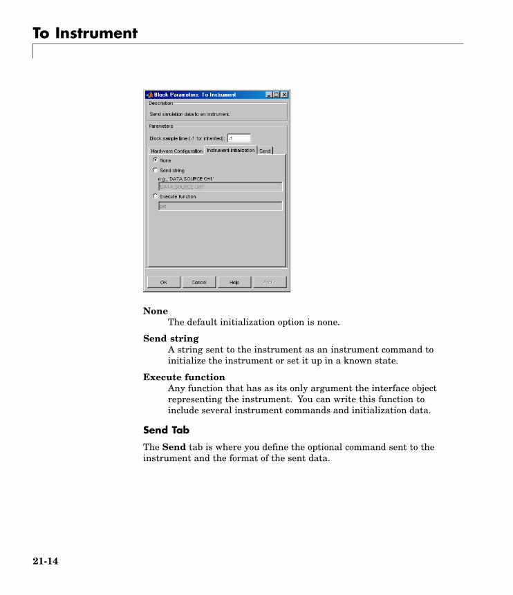
To Instrument
NoneThe default initialization option is none.
Send stringA string sent to the instrument as an instrument command toinitialize the instrument or set it up in a known state.
Execute functionAny function that has as its only argument the interface objectrepresenting the instrument. You can write this function toinclude several instrument commands and initialization data.
Send Tab
The Send tab is where you define the optional command sent to theinstrument and the format of the sent data.
21-14

To Instrument
CommandThis is the command that is sent to the instrument with theSimulink data. This command is optional—if you leave this fieldblank, the Simulink data is sent to the instrument without anyprefix or additional formatting.
Output formatYour options are ASCII, Binary, or Binblock (binary block —the binblock format is described in the binblockwrite functionreference page).
ASCII format stringAvailable only when the format is ASCII, this defines the formatstring for the data. For a list of formats, see the fprintf function.
PrecisionUsed for binary or binblock format. Your options are:
• 8-bit integer (default)
21-15

To Instrument
• 16-bit integer
• 32-bit integer
• 8-bit unsigned integer (default)
• 16-bit unsigned integer
• 32-bit unsigned integer
• 32-bit float
• 64-bit float
Byte orderWhen using binary or binblock format with more than 8 bits, youcan specify the instrument’s byte order for the data. Your optionsare Big Endian or Little Endian.
Note Hardware information shown in the dialog box is determinedand cached when the dialog box is first opened. To refresh the displaywith new values, restart MATLAB.
See Also Query Instrument, TCP/IP Receive, TCP/IP Send, UDP Receive, UDPSend
21-16

TCP/IP Receive
Purpose Receive data over TCP/IP from specified remote machine
Library Instrument Control Toolbox
Description The TCP/IP Receive block configures and opens an interface to aspecified remote address using the TCP/IP protocol. The configurationand initialization occur once at the start of the model’s execution.During the model’s run time, the block acquires data either in blockingmode or nonblocking mode.
Note You must have a license for both Instrument Control Toolbox andSimulink to use this block.
This block has no input ports. It has either one or two output ports,based on your selection of blocking or nonblocking mode. If you selectblocking mode then the block will have one output port corresponding tothe data it receives.
If you do not select blocking mode, the block will have two output ports,the Data port and the Status port.
A First In First Out (FIFO) buffer receives the data. At every timestep, the Data port outputs the requested values from the buffer. Innonblocking mode, the Status port indicates if the block has receivednew data.
21-17

TCP/IP Receive
Use the TCP/IP Receive block to read streaming data over a TCP/IPnetwork, using the Instrument Control Toolbox functionality inSimulink.
DialogBox
Use the Source Block Parameters dialog box to select yourcommunication parameters.
Remote addressEnter the IP address, name, or the Web server address of themachine from which you need to receive data. This field is emptyby default.
PortEnter the remote port on the remote machine you need to connectto. The default port value is 80. Valid port values are 1 to 65535.
Verify address and port connectivity ...Click this button to
21-18

TCP/IP Receive
• Check if the specified remote address is correct.
• Establish connection with the specified remote address andport.
Data sizeSpecify the output data size, or the number of values that shouldbe read at every simulation time step. The default size is [1 1].
Data typeSpecify the output data type to receive from the block. You canselect from the following values:
• single
• double
• int8
• uint8 (default)
• int16
• uint16
• int32
• uint32
Enable blocking modeSpecify if you want to block the simulation while receiving data.This option is selected by default. Clear this check box if you donot want the read operation to block the simulation.
If you enable blocking mode, the model will block the simulationwhile it is waiting for the requested data to be available.When you do not enable blocking mode, the simulation runscontinuously. The block has two output ports, Status and Data.The Data port contains the requested set of data at each timestep. The Status port contains 0 or 1 based on whether it receivednew data at the given time step. The following diagrams showthe difference between receiving data using blocking mode andnonblocking mode.
21-19

TCP/IP Receive
In this example, you start the simulation at time (t=0) andspecifies the amount of data to receive as 4 (set in the Data sizefield of the TCP/IP Receive Block Parameters dialog box). Oncethe simulation starts, the data is acquired asynchronously ina FIFO buffer.
Blocking Mode
The blocking mode simulation occurs like this:
• At time step 1: Simulink requests data and the buffer hasfour values available, the block fulfills the request withoutinterrupting the simulation. The block resets the buffer valueto 0.
• At time step 2: Simulink requests data again, and the bufferhas only three values, therefore it blocks the simulation until itreceives the fourth value. When the block receives the fourthvalue, it fulfills the request and resumes the simulation. Theblock resets the buffer value to 0.
21-20

TCP/IP Receive
• At time step 3: When Simulink requests data, the block hasfive values and it returns the first four that it received andresets the buffer to 1.
If the requested data is not received within the amount oftime specified in the Timeout field (of the TCP/IP ReceiveBlock Parameters dialog box), a Simulink error occurs and thesimulation is stopped.
Nonblocking Mode
Here the simulation is not blocked and runs continuously.
• At time step 1: Simulink requests data and the buffer has fourvalues available, the block fulfills the request and changes theStatus port value to 1, indicating that new data is available.The Data port at this point contains the newly received values.The block resets the buffer value to 0.
• At time step 2: Simulink requests data again, and the bufferhas only three values, and the block cannot return it as datasize is specified as 4. Therefore the block sets the Status port
21-21

TCP/IP Receive
value to 0, indicating that there is no new data. The Dataport contains the previously received value, and the buffer isat three (the number of values it has received since the lastrequest was fulfilled).
• At time step 3: When Simulink requests data here, the buffernow has five values and it returns the first four in the order itreceived and changes the Status Port value to 1.
TimeoutSpecify the amount of time that the model will wait for thedata during each simulation time step. The default value is 10(seconds). This field is disabled if you have not selected Enableblocking mode.
Block sample timeSpecify the sample time of the block during the simulation. Thisis the rate at which the block is executed during simulation. Thedefault value is 0.01 (seconds).
See Also Query Instrument, To Instrument, TCP/IP Send, UDP Receive, UDPSend
21-22

TCP/IP Send
Purpose Send data over TCP/IP to specified remote machine
Library Instrument Control Toolbox
Description The TCP/IP Send block sends data from your model to remote machinesusing the TCP/IP protocol. This data is sent at the end of the simulationor at fixed intervals during a simulation.
Note You must have a license for both Instrument Control Toolbox andSimulink to use this block.
The TCP/IP Send block has one input port. The size of the input portis dynamic, and is inherited from the driving block. This block has nooutput ports.
DialogBox
Use the Sink Block Parameters dialog box to select your communicationparameters.
21-23

TCP/IP Send
Remote addressSpecify the IP address, name, or the Web server address of themachine to which you need to send data. This field is empty bydefault.
PortSpecify the remote port on the host you need to send the data to.The default port value is 80. Valid port values are 1 to 65535.
Verify address and port connectivity ...Click this button to
• Check if the specified remote address is correct.
• Establish connection with the specified remote address andport.
Enable blocking modeSpecify if you want to block the simulation while sending data.This option is selected by default. Clear this check box if you donot want the write operation to block the simulation.
The following diagrams show the difference between sending datausing blocking mode and nonblocking mode.
Blocking mode
21-24

TCP/IP Send
In this example, you start the simulation at time (t=0). At timestep (T1), data output is initiated and simulation stops until theblock of data (B1) is sent to the specified remote address and port.Once the data is sent, simulation resumes until time step (T2),where the block initiates another data output and simulation isblocked until the block of data (B2) is sent to the remote addressand port, and the simulation resumes.
Nonblocking Mode – Scenario 1
In this scenario, the data output outpaces the simulation speed.Data output is initiated at the first time step (T1) and thecorresponding block of data (B1) is sent to the specified remoteaddress asynchronously. The simulation runs continuously inthis mode.
21-25

TCP/IP Send
Nonblocking Mode – Scenario 2
In this scenario the simulation speed outpaces the dataacquisition.
• At time step T1: The block of data B1 is sent to the specifiedremote address and port asynchronously.
• At time step T2: The simulation is blocked until the block ofdata B1 is sent completely. When the B1 is completely sent, thenew block of data B2 is sent asynchronously, and the simulationresumes.
Note Several factors, including network connectivity and modelcomplexity, can affect the simulation speed. This can cause bothnonblocking scenarios to occur within the same simulation.
21-26
TCP/IP Send
TimeoutSpecify the amount of time that the model will wait when datais sent during each simulation time step. The default value is10 (seconds). This field is unavailable if you have not enabledblocking mode.
See Also Query Instrument, To Instrument, TCP/IP Receive, UDP Receive, UDPSend
21-27
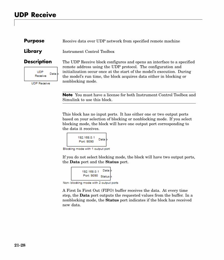
UDP Receive
Purpose Receive data over UDP network from specified remote machine
Library Instrument Control Toolbox
Description The UDP Receive block configures and opens an interface to a specifiedremote address using the UDP protocol. The configuration andinitialization occur once at the start of the model’s execution. Duringthe model’s run time, the block acquires data either in blocking ornonblocking mode.
Note You must have a license for both Instrument Control Toolbox andSimulink to use this block.
This block has no input ports. It has either one or two output portsbased on your selection of blocking or nonblocking mode. If you selectblocking mode, the block will have one output port corresponding tothe data it receives.
If you do not select blocking mode, the block will have two output ports,the Data port and the Status port.
A First In First Out (FIFO) buffer receives the data. At every timestep, the Data port outputs the requested values from the buffer. In anonblocking mode, the Status port indicates if the block has receivednew data.
21-28

UDP Receive
DialogBox
Use the Source Block Parameters dialog box to select your acquisitionmode and to set other configuration options.
Remote addressSpecify the IP address, name, or the Web server address of themachine from which you need to receive data. This field is emptyby default.
PortSpecify the remote port on the host you need to connect to. Thedefault port value is 9090. Valid port values are 1 to 65535.
Local portSpecify the port to bind on the local machine. The default value is-1, which automatically binds to an available port.
Verify address and port connectivity ...Click this button to
21-29

UDP Receive
• Check if the specified remote address is correct.
• Establish connection with the specified remote address andport.
Data sizeSpecify the output data size, or the number of values that shouldbe read at every simulation time step. The default size is [1 1].
Enable blocking modeSpecify if you want to block the simulation while receiving data.This option is selected by default. Clear this check box if you donot want the read operation to block the simulation.
If you enable blocking mode, the model will block the simulationwhile it is waiting for the requested data to be available. If youdo not enable blocking mode, the simulation runs continuously.The block has two output ports, Status and Data. The Data portcontains the requested set of data at each time step. The Statusport contains 0 or 1 based on whether it received new data atthe given time step. The following diagrams show the differencebetween receiving data using blocking mode and nonblockingmode.
In this example, you start the simulation at time (t=0) andspecifies the amount of data to receive as 4 (set in the Data sizefield of the UDP Receive Block Parameters dialog box). Once thesimulation starts, the data is acquired asynchronously in a FIFObuffer.
21-30

UDP Receive
Blocking Mode
The blocking mode simulation occurs like this:
• At time step 1: Simulink requests data and the buffer hasfour values available, the block fulfills the request withoutinterrupting the simulation. The block resets the buffer valueto 0.
• At time step 2: Simulink requests data again, and the bufferhas only three values, therefore it blocks the simulation until itreceives the fourth value. When the block receives the fourthvalue, it fulfills the request and resumes the simulation. Theblock resets the buffer value to 0.
• At time step 3: When Simulink requests data, the block hasfive values and it returns the first four that it received andresets the buffer to 1.
If the requested data is not received within the amount oftime specified in the Timeout field (of the UDP ReceiveBlock Parameters dialog box), a Simulink error occurs and thesimulation is stopped.
21-31
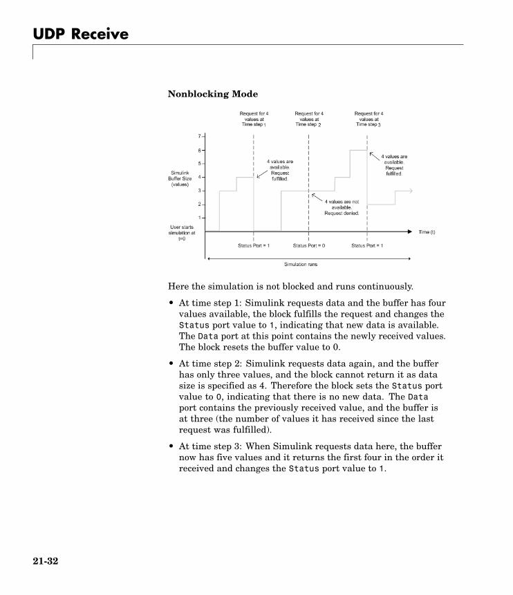
UDP Receive
Nonblocking Mode
Here the simulation is not blocked and runs continuously.
• At time step 1: Simulink requests data and the buffer has fourvalues available, the block fulfills the request and changes theStatus port value to 1, indicating that new data is available.The Data port at this point contains the newly received values.The block resets the buffer value to 0.
• At time step 2: Simulink requests data again, and the bufferhas only three values, and the block cannot return it as datasize is specified as 4. Therefore the block sets the Status portvalue to 0, indicating that there is no new data. The Dataport contains the previously received value, and the buffer isat three (the number of values it has received since the lastrequest was fulfilled).
• At time step 3: When Simulink requests data here, the buffernow has five values and it returns the first four in the order itreceived and changes the Status port value to 1.
21-32
UDP Receive
TimeoutSpecify the amount of time that the model will wait for thedata during each simulation time step. The default value isinf (seconds). This field is unavailable if you have not enabledblocking mode.
Block sample timeSpecify the sampling time of the block during simulation. Thedefault value is 0.01 (seconds).
Data typeSpecify the output data type to receive from the block. You canselect from the following values:
• single
• double
• int8
• uint8 (default)
• int16
• uint16
• int32
• uint32
See Also Query Instrument, To Instrument, TCP/IP Receive, TCP/IP Send, UDPSend
21-33

UDP Send
Purpose Send data over UDP network to specified remote machine
Library Instrument Control Toolbox
Description The UDP Send block sends data from your model to the specified remotemachine using the UDP protocol.
Note You must have a license for both Instrument Control Toolbox andSimulink to use this block.
The UDP Send block has one input port and it accepts both 1–D vectorand matrix data. This block has no output ports. The block inherits thedata type from the signal at the input port.
21-34

UDP Send
DialogBox
Use the Sink Block Parameters dialog box to select your acquisitionmode and to set other configuration options.
Remote addressSpecify the IP address, name, or the web server address of themachine to which you need to send data. This field is empty bydefault.
PortSpecify the remote port on the host you need to send the data to.The default port value is 80. Valid port values are 1 to 65535.
Local portSpecify the port to bind on the local machine. The default value is-1, which automatically binds to an available port.
21-35

UDP Send
Verify address and port connectivity ...Click this button to
• check if the specified remote address is correct.
• establish connection with the specified remote address and port.
Enable blocking modeSpecify if you want to block the simulation while sending data.This option is selected by default. Clear this check box if you donot want the write operation to block the simulation.
The following diagrams show the difference between sending datausing blocking mode and nonblocking mode.
Blocking Mode
In this example, you start the simulation at time (t=0). At timestep (T1), data output is initiated and simulation stops until theblock of data (B1) is sent to the specified remote address and port.Once the data is sent, simulation resumes until time step (T2),where the block initiates another data output and simulation isblocked until the block of data (B2) is sent to the remote addressand port, and the simulation resumes.
21-36

UDP Send
Nonblocking Mode – Scenario 1
In this scenario, the data output outpaces the simulation speed.Data output is initiated at the first time step (T1) and thecorresponding block of data (B1) is sent to the specified remoteaddress asynchronously. The simulation runs continuously inthis mode.
Nonblocking Mode – Scenario 2
21-37

UDP Send
In this scenario the simulation speed outpaces the dataacquisition.
• At time step T1: The block of data B1 is sent to the specifiedremote address and port asynchronously.
• At time step T2: The simulation is blocked until the block ofdata B1 is sent completely. When the B1 is completely sent, thenew block of data B2 is sent asynchronously, and the simulationresumes.
Here the simulation is nonblocking and occurs faster than thedata initiation. Data is initiated at time step T1, . When thesecond data initiation occurs at T2, the to the specified remoteaddress and port. The simulation resumes and B2 is sent. Whenthe next data initiation at T3 occurs, the simulation is blockeduntil B2 is sent.
Note Several factors, including network connectivity and modelcomplexity, can affect the simulation speed. This can cause bothnonblocking scenarios to occur within the same simulation.
See Also Query Instrument, To Instrument, TCP/IP Receive, TCP/IP Send, UDPReceive
21-38

A
Vendor DriverRequirements andLimitations
This appendix describes the requirements and limitations for the vendorGPIB and VISA drivers supported by Instrument Control Toolbox.
Driver Requirements (p. A-2) Required versions of vendors’drivers.
GPIB Driver Limitations by Vendor(p. A-3)
Known limitations with supportedGPIB drivers.
VISA Driver Limitations (p. A-7) Known limitations with supportedVISA drivers.
Note The limitations described in this appendix are restricted to thelimitations directly associated with using Instrument Control Toolbox.

A Vendor Driver Requirements and Limitations
Driver RequirementsYou can use Instrument Control Toolbox with the following GPIB and VISAdrivers.
Interface Vendor Minimum DriverRequirements
Advantech Advantech version 1.0
Agilent SICL versionH.012.02.00
Capital EquipmentCorporation
CEC-488 version 5.08
CONTEC API-GPLV version 1.33
ICS Electronics ICS 488.2 version2.0.3.15
IOTech IOTech version 1.0
Keithley Keithley-488 version5.08
MeasurementComputing Corporation
GPIB-32 version 2.12
GPIB
National Instruments NI-488 version 1.6
Agilent Agilent IO Librariesversion M.01.01.04
National Instruments NI-VISA version 3.0
VISA
Tektronix Tektronix VISA version2.0
See the following sections for a description of
• “GPIB Driver Limitations by Vendor” on page A-3
• “VISA Driver Limitations” on page A-7
A-2

GPIB Driver Limitations by Vendor
GPIB Driver Limitations by Vendor
In this section...
“Advantech” on page A-3
“Agilent Technologies” on page A-3
“Capital Equipment Corporation” on page A-4
“ICS Electronics” on page A-4
“IOTech” on page A-5
“Keithley” on page A-5
“Measurement Computing Corporation” on page A-6
AdvantechThe Advantech GPIB driver has these limitations:
• Asynchronous read and write operations are not supported. Therefore,Advantech GPIB objects do not support the following toolbox functionality:
- The readasync function
- The async flag for the fprintf and fwrite functions
- BytesAvailableAction and OutputEmptyAction properties
Agilent TechnologiesThe Agilent GPIB driver has these limitations:
• Asynchronous read and write operations are not supported. Therefore,Agilent GPIB objects do not support the following toolbox functionality:
- The readasync function
- The async flag for the fprintf and fwrite functions
- BytesAvailableAction and OutputEmptyAction properties
• The End Or Identify (EOI) line is not asserted when the End-Of-String(EOS) character is written to the hardware. Therefore, when the EOSModeproperty is configured to write and the EOIMode property is configured to
A-3
A Vendor Driver Requirements and Limitations
on, the EOI line is not asserted when the EOSCharCode property valueis written to the hardware.
• All eight bits are used for the EOS comparison. Therefore, the only valuesupported by the CompareBits property is 8.
• A board index value of 0 is not supported.
• An error is not reported for an invalid primary address. Instead, the readand write operations will time out.
Capital Equipment CorporationThe Capital Equipment Corporation (CEC) GPIB driver has these limitations:
• Asynchronous read operations are not supported. Therefore, CEC GPIBobjects do not support the following toolbox functionality:
- The readasync function
- The async flag for the fprintf and fwrite functions
- The BytesAvailableAction and OutputEmptyAction properties
• The Handshake and Bus Management line values are not provided. TheBusManagementStatus and HandshakeStatus properties always returnthe line values as on.
• The EOI line is not asserted when the EOS character is written to thehardware. Therefore, when the EOSMode property is configured to writeand the EOIMode property is configured to on, the EOI line is not assertedwhen the EOSCharCode property value is written to the hardware.
• All eight bits are used for the EOS comparison. Therefore, the only valuesupported by the CompareBits property is 8.
• You should not simultaneously use a GPIB controller address of 0 and aninstrument primary address of 0.
ICS ElectronicsThe ICS Electronics GPIB adaptor only works with their USB GPIB controller.However, you can still use their other controllers (PCI/PCMCIA) by using themcc adaptor. See Solution 1-1BFZ2 on the MathWorks support Web site.
A-4

GPIB Driver Limitations by Vendor
IOTechThe IOTech GPIB driver has these limitations:
• Asynchronous read and write operations are not supported. Therefore,IOTech GPIB objects do not support the following toolbox functionality:
- The readasync function
- The async flag for the fprintf and fwrite functions
- The BytesAvailableAction and OutputEmptyAction properties.
• Incorrect values are returned for the REN and IFC bus management lines.The BusManagementStatus property always returns a value of on for theRemoteEnable and the InterfaceClear fields.
• The EOI line is not asserted when the EOS character is written to thehardware. Therefore, when the EOSMode property is configured to writeand the EOIMode property is configured to on, the EOI line will not beasserted when the EOSCharCode property value is written to the hardware.
KeithleyThe Keithley GPIB driver has these limitations:
• Asynchronous read and write operations are not supported. Therefore,Keithley GPIB objects do not support the following toolbox functionality:
- The readasync function
- The async flag for the fprintf and fwrite functions
- The BytesAvailableAction and OutputEmptyAction properties
• The Handshake and Bus Management line values are not provided. TheBusManagementStatus and HandshakeStatus properties always returnthe line value as on.
• The EOI line is not asserted when the EOS character is written to thehardware. Therefore, when the EOSMode property is configured to writeand the EOIMode property is configured to on, the EOI line will not beasserted when the EOSCharCode property value is written to the hardware.
• All eight bits are used for the EOS comparison. Therefore, the only valuesupported by the CompareBits property is 8.
A-5

A Vendor Driver Requirements and Limitations
• You should not simultaneously use a GPIB controller address of 0 and aninstrument primary address of 0.
Measurement Computing CorporationThe Measurement Computing Corporation GPIB driver does not supportasynchronous notification for the completion of read and write operations.Therefore, Measurement Computing Corporation GPIB objects do not supportthe following toolbox functionality:
• The readasync function
• The async flag for the fprintf and fwrite functions
• The BytesAvailableAction and OutputEmptyAction properties
A-6

VISA Driver Limitations
VISA Driver Limitations
In this section...
“Agilent Technologies” on page A-7
“National Instruments” on page A-7
Agilent TechnologiesThe Agilent VISA driver has these known limitations:
• Asynchronous read and write operations for GPIB, GPIB-VXI andVXI VISA objects are not supported. Therefore, the following toolboxfunctionality is not supported for these objects:
- The readasync function
- The BytesAvailableAction and OutputEmptyAction properties
• All eight bits are used for the EOS comparison. Therefore, the only valuesupported by the CompareBits property is 8.
National InstrumentsThe National Instruments VISA driver uses all eight bits for the EOScomparison. Therefore, the only value that the CompareBits propertysupports is 8.x
A-7

A Vendor Driver Requirements and Limitations
A-8

B
Bibliography
[1] Axelson, Jan, Serial Port Complete, Lakeview Research, Madison, WI,1998.
[2] Courier High Speed Modems User’s Manual, U.S. Robotics, Inc., Skokie,IL, 1994.
[3] TIA/EIA-232-F, Interface Between Data Terminal Equipment and DataCircuit-Terminating Equipment Employing Serial Binary Data Interchange.
[4] Getting Started with Your AT Serial Hardware and Software for Windows98/95, National Instruments, Inc., Austin, TX, 1998.
[5] HP E1432A User’s Guide, Hewlett-Packard Company, Palo Alto, CA, 1997.
[6] HP 33120A Function Generator/Arbitrary Waveform Generator User’sGuide, Hewlett-Packard Company, Palo Alto, CA, 1997.
[7] HP VISA User’s Guide, Hewlett-Packard Company, Palo Alto, CA, 1998.
[8] NI-488.2MTM User Manual for Windows 95 and Windows NT, NationalInstruments, Inc., Austin, TX, 1996.
[9] NI-VISATM User Manual, National Instruments, Inc., Austin, TX, 1998.
[10] IEEE Std 488.2-1992, IEEE Standard Codes, Formats, Protocols, andCommon Commands for Use with IEEE Std 4881.-1987, IEEE StandardDigital Interface for Programmable Instrumentation, Institute of Electricaland Electronics Engineers, New York, NY, 1992.
[11] Instrument Communication Handbook, IOTech, Inc., Cleveland, OH,1991.

B Bibliography
[12] TDS 200-Series Two Channel Digital Oscilloscope Programmer Manual,Tektronix, Inc., Wilsonville, OR.
[13] Stevens, W. Richard, TCP/IP Illustrated, Volume 1, Addison-Wesley,Boston, MA, 1994.
B-2

Index
IndexAA16/A24/A32 memory space 5-15active state, serial port 6-6ActualLocation property 20-2adaptors 1-8
finding with instrhwinfo 1-13add function 18-2address configuration
GPIB object 4-18VISA-GPIB object 5-7VISA-GPIB-VXI object 5-25VISA-RSIB object 5-41VISA-TCPIP object 5-37VISA-USB object 5-33VISA-VXI object 5-12
Agilent Technologiesadaptors 1-8E1432A registers, example of 5-17
Alias property 20-3array, instrument object
creating 3-3example of 4-40
ASCIIcontrol characters 6-34read operations 4-20
versus binary 3-21serial data 6-9write operations 4-20
versus binary 3-15asynchronous
read operations 3-23readasync example 4-23readasync example using events 4-34ReadAsyncMode, example of 6-20
serial port 6-10write operations 3-17
ATN line 4-7serial poll 4-39
Bbase properties 2-5
list for interface objects 19-2BaudRate property 20-4binary
floating-point arithmetic standard 12-8read operations 4-22
versus text 3-21write operations 3-15
binblockread function 18-6binblockwrite function 18-9Block Library 16-3blocks
Query Instrument 21-2TCP/IP Receive 21-17TCP/IP Send 21-23To Instrument 21-10UDP Receive 21-28UDP Send 21-34using the Instrument Control Toolbox block
library 16-1BoardIndex
GPIB object 4-18VISA-GPIB object 5-8VISA-GPIB-VXI object 5-26
BoardIndex property 20-6break-interrupt event
datagram-received 7-21serial port 6-25
BreakInterruptFcn property 20-8buffer
clearing hardware 4-27input 3-20output 3-14values versus bytes 3-14
bus and connector, GPIB 4-4BusManagementStatus
GPIB interface management lines 4-8BusManagementStatus property 20-10
example of 20-10
Index-1

Index
ByteOrder property 20-12bytes versus values 3-14bytes-available event 4-29
example 4-34BytesAvailable
example of 3-24BytesAvailable property 20-13BytesAvailableFcn property 20-14BytesAvailableFcnCount property 20-17BytesAvailableFcnMode property 20-18BytesToOutput
output buffer 3-14BytesToOutput property 20-20
Ccallback functions
creating 4-32enabling after they error 4-33executing 4-32instrcallback, example 4-28
callback propertiesGPIB object 4-29saving property values to a MAT-file 12-2serial port object 6-25TCP/IP object 7-21UDP object 7-21
CD pin 6-8ChassisIndex property 20-21clear
cleaning up the MATLAB environment 3-25clear function 18-12clrdevice
example of 4-27clrdevice function 18-13commit function 18-14CompareBits property 20-23configuring property values 3-9ConfirmationFcn property 20-24connect function 18-15
connecting to the instrument 2-4interface object 3-5
constructor 3-2finding with instrhwinfo 1-13
control characters 6-34control pins 6-7
using 6-30controllers, GPIB 4-4creation function 3-2CTS pin 6-8
Ddata bits 6-11data format
serial port 6-9data lines 4-7DataBits property 20-25DatagramAddress property 20-26DatagramPort property 20-27DatagramReceivedFcn property 20-28DatagramTerminateMode property 20-29DataTerminalReady property 20-30DAV line 4-8DCE 6-3dec2bin 12-9default property values 3-10delete
cleaning up the MATLAB environment 3-25delete function 18-17demos 1-9device groups 8-14device objects 8-1
compared to interface objects 2-3connecting 8-7control commands 8-12creating 8-5device groups 8-14methods 8-10
devicereset function 18-19
Index-2

Index
DIO lines 4-7disconnect function 18-20disconnecting from the instrument 3-25disp function 18-22display summary
GPIB object 4-16serial port object 6-17TCP/IP object 7-5UDP object 7-11VISA-GPIB object 5-7VISA-GPIB-VXI object 5-24VISA-RSIB object 5-40VISA-serial object 5-28VISA-TCPIP object 5-36VISA-USB object 5-32VISA-VXI object 5-11
documentation examples 1-9dot notation
configuring property values 3-9returning property values 3-9saving property values to an M-file 12-2
DriverName property 20-31DriverSessions property 20-32DriverType property 20-33DSR pin 6-8DTE 6-3DTR pin 6-8
Eechotcpip function 18-23echoudp function 18-24enable registers 4-10EOI line 4-7
example of 4-25EOIMode
example 4-25EOIMode property 20-34EOS character 4-25
EOSCharCode 20-35
EOSCharCodeexample 4-25
EOSCharCode property 20-35EOSMode
example 4-25EOSMode property 20-36error event 4-30ErrorFcn property 20-39ESER 4-13even parity 6-12event reporting 4-10event types
GPIB object 4-29serial port object 6-25TCP/IP object 7-21UDP object 7-21
events 1-7example index 1-9examples
communicating with a GPIB instrument 1-21communicating with a GPIB instrument
through a device object 1-25communicating with a GPIB-VXI
instrument 1-22communicating with a serial port
instrument 1-24connecting two modems 6-31executing a serial poll 4-39executing a trigger, GPIB 4-36parsing input data using scanstr 4-24reading binary data, GPIB 4-22reading text data versus reading binary
data 3-21recording information to disk 12-10understanding EOI and EOS 4-25using events and callbacks, GPIB 4-33using events and callbacks, serial port 6-28using software handshaking 6-35writing and reading text data, GPIB 4-20
Index-3

Index
writing and reading text data, serialport 6-22
writing text data versus writing binarydata 3-15
Ffclose
disconnecting from the instrument 3-25fclose function 18-25fgetl
reading text data 3-21fgetl function 18-27
example of 18-29fgets
reading text data 3-21fgets function 18-31
example of 18-33FlowControl
example of 6-35FlowControl property 20-41flushinput function 18-35flushoutput function 18-36fopen
connecting to the instrument 3-5fopen function 18-37format
record file 12-8serial data 6-9
fprintfexample 4-21writing text data 3-16
fprintf function 18-39fread
example 4-23reading binary data 3-21
fread function 18-43fscanf
example 4-21reading text data 3-21
fscanf function 18-48full-duplex 6-7function handles 4-32functions
add 18-2binblockread 18-6binblockwrite 18-9clear 18-12clrdevice 18-13commit 18-14connect 18-15delete 18-17devicereset 18-19disconnect 18-20disp 18-22echotcpip 18-23echoudp 18-24fclose 18-25fgetl 18-27fgets 18-31flushinput 18-35flushoutput 18-36fopen 18-37fprintf 18-39fread 18-43fscanf 18-48fwrite 18-53get 18-57
GPIB object 3-7geterror 18-59gpib 18-60
creating object 4-15icdevice 18-64inspect 18-69instrcallback 18-71
example 4-28example with binary data 4-34
instrfind 18-73instrfindall 18-76
Index-4

Index
instrhelp 18-79introduction 1-31
instrhwinfo 18-81introduction 1-12
instrnotify 18-86instrreset 18-89invoke 18-90isvalid 18-92iviconfigurationstore 18-93length 18-94load 18-95makemid 18-97memmap 18-99mempeek 18-101mempoke 18-103memread 18-105memunmap 18-108memwrite 18-110methods 18-112midedit 18-113midtest 18-114obj2mfile 18-115propinfo 18-118
introduction 1-31query 18-121readasync 18-124
example 4-23example using events 4-34
record 18-127remove 18-129resolvehost 18-130save 18-131scanstr 18-133selftest 18-136serial 18-137serialbreak 18-139set 18-140
configuring property values 3-9GPIB object 3-6
size 18-143
spoll 18-144stopasync 18-146tcpip 18-148tmtool 18-151trigger 18-152
example 4-37udp 18-153update 18-156visa 18-159
fwriteexample of 3-17writing binary data 3-16
fwrite function 18-53
GGeneric instrument drivers 11-1
using at the command line 11-13using with Test & Measurement Tool 11-9writing 11-3
getGPIB object properties 3-7
get function 18-57geterror function 18-59gpib
creating GPIB object 4-15gpib function 18-60GPIB object
address configuration 4-18base properties 19-2callback properties 4-29creation 4-15display summary 4-16event types 4-29events and callbacks 4-28object-specific properties 19-5
GPIB standard 4-3bus and connector 4-4controllers 4-4data 4-5
Index-5

Index
data lines 4-7enable registers 4-10event reporting 4-10handshake lines 4-8interface management lines 4-7listeners 4-4status registers 4-10talkers 4-4
GPIB-VXI interface 5-22Group Execute Trigger 4-36GUI
instredit 18-113Property Inspector 2-6
Hhalf-duplex 6-7handshake lines 4-8HandshakeStatus
GPIB handshake lines 4-10HandshakeStatus property 20-43handshaking
hardware 6-34serial port object 6-33software 6-34
hardware handshaking 6-34hardware resources 1-12HardwareAssets property 20-44help 1-31
overview 1-9hex2dec 12-9hexadecimal values
converting to decimal values 12-9saved to record file 12-12
high-level memory functions, VXI 5-16HP-IB 4-3HwIndex property 20-45HwName property 20-46
Iicdevice function 18-64IEEE
488 standard 4-3754 standard 12-8format saved to record file 12-8
IFC line 4-7inactive state, serial port 6-6input buffer 3-20InputBufferSize property 20-47inspect function 18-69instrcallback
example 4-28example using binary data 4-34
instrcallback function 18-71instrfind function 18-73instrfindall function 18-76instrhelp
example of 1-31instrhelp function 18-79instrhwinfo
adaptors, finding 1-13example of 1-12object constructors, finding 1-13
instrhwinfo function 18-81instrnotify function 18-86instrreset function 18-89instrument control session 2-1
loading 12-2saving 12-2
Instrument Control Toolbox block libraryusing 16-1
Instrument Control Toolbox Block Libraryopening 16-3
instrument object 2-2array
creating 3-3example of 4-40
configuring property values 3-9during object creation 3-3
Index-6

Index
connecting to instrument 2-4creating 2-2disconnecting from instrument 2-8input buffer 3-20interface-specific properties 19-5invalid 3-25loading 12-2output buffer 3-14reading data 3-19returning from memory 18-73returning property values 2-5saving 12-2specifying property names 3-10writing data 3-13
InstrumentModel property 20-48interface
driver adaptor 1-8GPIB object 4-15serial port object 6-16TCP/IP object 7-4UDP object 7-10VISA-GPIB object 5-5VISA-GPIB-VXI object 5-23VISA-RSIB object 5-39VISA-serial object 5-27VISA-TCPIP object 5-35VISA-USB object 5-31VISA-VXI object 5-10
interface management lines 4-7interface object 3-1
base properties 19-2compared to device object 2-2connecting to instrument 3-5creating 3-2disconnecting from instrument 3-25returning property values 3-6
Interface property 20-49interface-specific properties
list by object type 19-5InterfaceIndex property 20-50
InterruptFcn property 20-51invalid instrument object 3-25invoke function 18-90isvalid function 18-92IVI drivers 10-1
constructing device object 10-9creating MATLAB IVI driver 10-6IVI configuration store 10-11shared components 10-3
iviconfigurationstore function 18-93
LLANName property 20-52length function 18-94listeners 4-4load 12-4load function 18-95loading instrument objects
from M-file 12-3from MAT-file 12-4
LocalHost property 20-53LocalPort property 20-54LocalPortMode property 20-55logical unit 4-18LogicalAddress property 20-56LogicalName property 20-57LogicalNames property 20-58low-level memory functions, VXI 5-19
Mmakemid function 18-97ManufacturerID property 20-59MappedMemoryBase property 20-60MappedMemorySize property 20-62mark parity 6-12MasterLocation property 20-63MAT-file
instrument objects, saving to 12-4
Index-7

Index
properties, saving to 12-2memmap function 18-99memory mapping, VXI 5-19MemoryBase property 20-64MemoryIncrement property 20-66MemorySize property 20-69MemorySpace property 20-71mempeek function 18-101mempoke function 18-103memread function 18-105memunmap function 18-108memwrite function 18-110message-based communication, VXI 5-12methods function 18-112midedit function 18-113midtest function 18-114ModelCode property 20-73
NNagle’s algorithm 20-126Name property 20-74
iviconfigurationstore 20-76National Instruments
adaptors 1-8NDAC line 4-8NRFD line 4-8null modem cable 6-4
Oobj2mfile
example 12-2obj2mfile function 18-115object constructor 3-2
finding with instrhwinfo 1-13object-specific properties 2-5ObjectVisibility property 20-77odd parity 6-12online help 1-31
output buffer 3-14output-empty event 4-30OutputBufferSize property 20-79OutputEmptyFcn property 20-80
PParent property 20-82parity bit 6-12Parity property 20-83parsing input data 4-24pin-status event 6-26PinStatus
example of 6-31PinStatus property 20-85PinStatusFcn property 20-87Port property 20-89PrimaryAddress
GPIB object 4-18VISA-GPIB object 5-8VISA-GPIB-VXI object 5-26
PrimaryAddress property 20-91ProcessLocation property 20-93properties
ActualLocation 20-2Alias 20-3BaudRate 20-4BoardIndex 20-6BreakInterruptFcn 20-8BusManagementStatus 20-10ByteOrder 20-12BytesAvailable 20-13BytesAvailableFcn 20-14BytesAvailableFcnCount 20-17BytesAvailableFcnMode 20-18BytesToOutput 20-20characteristics 1-31ChassisIndex 20-21CompareBits 20-23ConfirmationFcn 20-24
Index-8

Index
DataBits 20-25DatagramAddress 20-26DatagramPort 20-27DatagramReceivedFcn 20-28DatagramTerminateMode 20-29DataTerminalReady 20-30DriverName 20-31DriverSessions 20-32DriverType 20-33EOIMode 20-34EOSCharCode 20-35EOSMode 20-36ErrorFcn 20-39FlowControl 20-41HandshakeStatus 20-43HardwareAssets 20-44HwIndex 20-45HwName 20-46InputBufferSize 20-47InstrumentModel 20-48Interface 20-49InterfaceIndex 20-50InterruptFcn 20-51LANName 20-52LocalHost 20-53LocalPort 20-54LocalPortMode 20-55LogicalAddress 20-56LogicalName 20-57LogicalNames 20-58ManufacturerID 20-59MappedMemoryBase 20-60MappedMemorySize 20-62MasterLocation 20-63MemoryBase 20-64MemoryIncrement 20-66MemorySize 20-69MemorySpace 20-71ModelCode 20-73
Name 20-74iviconfigurationstore 20-76
ObjectVisibility 20-77OutputBufferSize 20-79OutputEmptyFcn 20-80Parent 20-82Parity 20-83PinStatus 20-85PinStatusFcn 20-87Port 20-89PrimaryAddress 20-91ProcessLocation 20-93PublishedAPIs 20-94ReadAsyncMode 20-95RecordDetail 20-97RecordMode 20-98RecordName 20-100RecordStatus 20-101RemoteHost 20-102RemotePort 20-103RequestToSend 20-104Revision 20-105RsrcName 20-106SecondaryAddress 20-108SerialNumber 20-110ServerDescription 20-111Sessions 20-112Slot 20-113SoftwareModules 20-114SpecificationVersion 20-115Status 20-116StopBits 20-117Tag 20-119Terminator 20-120Timeout 20-122TimerFcn property 20-123TimerPeriod property 20-125TransferDelay 20-126TransferStatus 20-127TriggerFcn 20-129
Index-9

Index
TriggerLine 20-130TriggerType 20-131Type 20-132UserData 20-134ValuesReceived 20-135ValuesSent 20-137Vendor 20-139
Property Inspector 2-6interface objects 3-11
property valuesbase 2-5
for interface objects 19-2configuring 3-9
during object creation 3-3default 3-10interface-specific 19-5object-specific 2-5returning 2-5returning from interface objects 3-6saving 12-2specifying names 3-10
propinfoexample of 1-31
propinfo function 18-118PublishedAPIs property 20-94
Qquery function 18-121Query Instrument block 21-2
Rread operations
asynchronous 4-23using events 4-34
asynchronous versus synchronous 3-23binary 4-22
versus text 3-21
completingGPIB object 4-20serial port object 6-22UDP object 7-15
GPIB registers 4-14register-based, VXI 5-12synchronous 3-23text 4-20
versus binary 3-21readasync
asynchronous read operations 3-23example 4-23example using events 4-34
readasync function 18-124ReadAsyncMode
asynchronous read operations 6-20example of 6-20
ReadAsyncMode property 20-95record
example 12-11record file
creating multiple files 12-7file name 12-8format 12-8
record function 18-127RecordDetail
example 12-11format, record file 12-8
RecordDetail property 20-97RecordMode
example 12-11multiple record files, creating 12-7
RecordMode property 20-98RecordName
example 12-11specifying a record file name 12-8
RecordName property 20-100RecordStatus property 20-101register-based communication, VXI 5-12
Index-10

Index
high-level memory functions, exampleof 5-16
low-level memory functions, example of 5-19registers
Agilent E1432A, example of 5-17reading and writing 4-14
serial poll 4-40Service Request Enable 4-12Standard Event Status 4-13Standard Event Status Enable 4-13Status Byte 4-12
RemoteHost property 20-102RemotePort property 20-103remove function 18-129REN line 4-7RequestToSend 20-104resolvehost function 18-130resource name
visa input argument 18-159returning objects from memory 18-73returning property values 2-5
interface object 3-6Revision property 20-105RI pin 6-8RS-232 standard 6-3RsrcName property 20-106RTS pin 6-8
Ssave function 18-131saving instrument objects
to M-file 12-2to MAT-file 12-4
SBR 4-12scanstr 4-24scanstr function 18-133SCPI 4-3Secondary VISA 5-4SecondaryAddress
GPIB object 4-18VISA-GPIB object 5-8VISA-GPIB-VXI object 5-26
SecondaryAddress property 20-108selftest function 18-136serial
creating a serial port object 6-16serial function 18-137serial poll 4-39serial port
configuring via operating system 6-13connecting two devices 6-3data format 6-9RS-232 standard 6-3signal and pin assignments 6-5
serial port objectbase properties 19-2callback properties 6-25configuring communications 6-19control pins 6-7
using 6-30creation 6-16display summary 6-17event types 6-25events and callbacks 6-25handshaking 6-33object-specific properties 19-6writing data 6-20
serialbreak function 18-139SerialNumber property 20-110ServerDescription property 20-111Service Request Enable Register 4-12SESR 4-13session 2-1
loading 12-2saving 12-2
Sessions property 20-112set
configuring property values 3-9GPIB object properties 3-6
Index-11

Index
saving property values to an M-file 12-2set function 18-140setserial 6-14signal state
GPIB 4-6serial port 6-6
Simulink blockTCP/IP Receive 21-17TCP/IP Send 21-23UDP Receive 21-28UDP Send 21-34
Simulink Library Browser 16-4size function 18-143Slot property 20-113software handshaking 6-34SoftwareModules property 20-114space parity 6-12SpecificationVersion property 20-115spoll 4-40spoll function 18-144SRER 4-12SRQ line 4-7
serial poll 4-39Standard Event Status Enable Register 4-13Standard Event Status Register 4-13start bit 6-11Status Byte Register 4-12Status property 20-116status registers 4-10stop bit 6-11stopasync function 18-146StopBits property 20-117stty 6-15synchronous
read operations 3-23serial port 6-10write operations 3-17
TTag property 20-119talkers 4-4TCP/IP object
callback properties 7-21creation 7-4display summary 7-5event types 7-21writing data 7-14
TCP/IP Receive block 21-17TCP/IP Send block 21-23tcpip
creating a TCP/IP object 7-4tcpip function 18-148TCPIP object
object-specific properties 19-7termination
EOSCharCode, example of 4-26read operations
GPIB object 4-20serial port object 6-22UDP object 7-15
Terminator, example 6-31write operations
GPIB object 4-19serial port object 6-21UDP and TCIP objects 7-14
Terminatorexample 6-31
Terminator property 20-120Test & Measurement Tool 13-1
connecting to instrument 13-8exporting data 13-10exporting objects 13-10getting started 1-16hardware 13-4instrument drivers 13-16instrument objects 13-12saving the session 13-11
text
Index-12

Index
read operations 4-20versus binary 3-21
write operations 4-20versus binary 3-15
Timeout property 20-122timer event 4-30tmtool
See also Test & Measurement Tool 13-1tmtool function 18-151To Instrument block 21-10toolbox components
interface driver adaptor 1-8M-files 1-7
TransferDelay property 20-126TransferStatus property 20-127trigger
example of 4-37trigger function 18-152TriggerFcn property 20-129TriggerLine property 20-130TriggerType property 20-131troubleshooting
serial ports 6-13tutorials 1-9Type property 20-132
Uudp
creating a UDP object 7-10udp function 18-153UDP object
callback properties 7-21creation 7-10display summary 7-11event types 7-21object-specific properties 19-7writing data 7-14
UDP Receive block 21-28UDP Send block 21-34
update function 18-156UserData
saving values to a MAT-file 12-2UserData property 20-134
Vvalues versus bytes 3-14ValuesReceived property 20-135ValuesSent property 20-137Vendor property 20-139VISA
secondary 5-4visa function 18-159VISA-GPIB object
address configuration 5-7base properties 19-2creation 5-5display summary 5-7object-specific properties 19-8
VISA-GPIB-VXI objectaddress configuration 5-25base properties 19-2creation 5-23display summary 5-24object-specific properties 19-8
VISA-RSIB objectaddress configuration 5-41creation 5-39display summary 5-40object-specific properties 19-9
VISA-serial objectbase properties 19-2communication configuration 5-29creation 5-27display summary 5-28object-specific properties 19-10
VISA-TCPIP objectaddress configuration 5-37creation 5-35
Index-13

Index
display summary 5-36object-specific properties 19-10
VISA-USB objectaddress configuration 5-33creation 5-31display summary 5-32object-specific properties 19-11
VISA-VXI objectaddress configuration 5-12base properties 19-2creation 5-10display summary 5-11object-specific properties 19-11register-based communication 5-12
VXI interface 5-9VXIplug&play drivers 9-1
constructing device object 9-8creating MATLAB VXIplug&play driver 9-5
WWorkspace browser
Display Hardware Info 1-15Display Summary 4-16
Instrument Help 1-31Property Inspector 2-6
write operationsasynchronous 3-17binary 3-15completing
GPIB object 4-19serial port object 6-21UDP and TCP/IP objects 7-14
GPIB registerscommon commands 4-14serial poll example 4-40
register-based, VXI 5-12synchronous 3-17text
example 4-20text versus binary 3-15values versus bytes 3-14
XXoff 6-34Xon 6-34
Index-14