instructors - itcaitcaonline.com/wp-content/uploads/2013/11/itca-module-i-notes... · instructors...
TRANSCRIPT
Slide 1 ITCA UST Installation and Closure February 28 – March 1, 2012
___________________________________
___________________________________
___________________________________
___________________________________
___________________________________
___________________________________
___________________________________
Slide 2 Instructors
Kevin HendersonKevin Henderson Consulting LLC,
Brandon, MS
601-706-4463 (office)
601-825-1985 (cell)
John KneeceUnderground Storage Training and
Consulting LLC, Leesville, SC
803-429-5271 (cell)
803-532-2354 (home)
___________________________________
___________________________________
___________________________________
___________________________________
___________________________________
___________________________________
___________________________________
Slide 3 COURSE OVERVIEW
– INTRODUCTION
– TANK INSTALLATION
• Chapter 1: Sources of Information on Tank Installation
• Chapter 2: Tank Rules and Regulations
• Chapter 3: Material Handling & Pre-Installation Testing
• Chapter 4: Excavating and Trenching
• Chapter 5: Supplementary Hold Down for Tanks
• Chapter 6: Backfill and Compaction
• Chapter 7: Secondary Containment & Overfill/Spill Prevention
___________________________________
___________________________________
___________________________________
___________________________________
___________________________________
___________________________________
___________________________________

Slide 4 COURSE OVERVIEW
– INSTALLATION (continued)
• Chapter 8: Piping Layout, Techniques and Materials
• Chapter 9: Installation of Tank Related Equipment
• Chapter 10: Tank-System Electrical Installation
• Chapter 11: Tank-System Release Detection
• Chapter 12: Corrosion Control
• Chapter 13: Tank System Testing
• Chapter 14: Safety Requirements for Tank Installation
___________________________________
___________________________________
___________________________________
___________________________________
___________________________________
___________________________________
___________________________________
Slide 5 COURSE OVERVIEW
– CLOSURE
• Chapter 1: Industry/Regulatory Documents
• Chapter 2: Safety Requirements
• Chapter 3: Release Reporting
• Chapter 4: Temporary Closure
• Chapter 5: Permanent Closure
• Chapter 6: Removal From Ground
• Chapter 7: Closure in Place
• Chapter 8: Sampling/Analytical Requirements
• Chapter 9: Making Tanks Safe
• Chapter 10: Tank Cleaning
___________________________________
___________________________________
___________________________________
___________________________________
___________________________________
___________________________________
___________________________________
Slide 6 Introduction
• There are many aspects of the industry that individuals must become familiar with in order to provide effective oversight of Underground Storage Tank (UST) installations and closures.
• This course will discuss practically every aspect of tank installation/closure but no class is a substitute for practical, hands-on “real world” experience.
___________________________________
___________________________________
___________________________________
___________________________________
___________________________________
___________________________________
___________________________________
Slide 7 Introduction
Oversight Responsibilities
Be present at the job site during the following installation critical junctures:
(i) Excavation immediately prior to tank and piping installation and during backfill and compaction
(ii) After excavation and prior to setting tank and piping
(iii) Setting of the UST and piping
(iv) Connection of piping and UST system components
(v) Installation of UST system restraining devices, and
(vi) Tightness testing of the UST system during installation
___________________________________
___________________________________
___________________________________
___________________________________
___________________________________
___________________________________
___________________________________
Slide 8 Introduction
Oversight Responsibilities
Be present at the job site during the following closure critical junctures:
(i) De-vaporization, inerting, and cleaning of the tank
(ii) Testing the atmosphere in and around the tanks
(iii) Excavation of material around the tank and piping
(iv) Removal of the tank and piping from the excavation and job site
(v) Cutting or destroying the tank if done on site, and
(vi) When closing in place, filling the tanks with an inert material
___________________________________
___________________________________
___________________________________
___________________________________
___________________________________
___________________________________
___________________________________
Slide 9 Chapter 1: Sources of Information
Why you need to be familiar with codes
– Regulations refer to and rely on various industry codes, practices and documents to determine the proper techniques for tank system installation.
• PEI (Petroleum Equipment Institute)• API (American Petroleum Institute)• STI (Steel Tank Institute)• FTPI (Fiberglass Tank & Pipe Institute)• NFPA (National Fire Prevention Association• IFC (International Fire Code)• UL (Underwriters Laboratories)• Manufacturers
___________________________________
___________________________________
___________________________________
___________________________________
___________________________________
___________________________________
___________________________________

Slide 10 Chapter 1: Sources of Information
Why contractors need to be familiar with codes
– Even if the contractor thinks there is a better way, the contractor must still follow recognized codes.
– If litigation occurs, lawyers will want to know specifically what code, standard or recommended practice was used
– If contractor didn’t follow codes, may be found liable.
___________________________________
___________________________________
___________________________________
___________________________________
___________________________________
___________________________________
___________________________________
Slide 11 Chapter 1: Sources of Information
Law vs. Regulation
• Law – Enabling legislation (statute) that creates government agencies and establishes their authority to develop and enforce rules.
• Regulation – Rules adopted by agencies intended to carry out policies established by laws.
• Code (Recommended Practice, Industry Standard, Manufacturers Instructions, etc.) – Documents developed by non-governmental organizations that describe specific procedures or practices.
___________________________________
___________________________________
___________________________________
___________________________________
___________________________________
___________________________________
___________________________________
Slide 12 Chapter 1: Sources of Information
Adoption by Reference
– It is common for rules to make reference to industry created documents.
– Many of these documents are intended only as “recommended practices”.
– Because the rules commonly incorporate these documents by reference, they become enforceable as “law”.
___________________________________
___________________________________
___________________________________
___________________________________
___________________________________
___________________________________
___________________________________

Slide 13 Chapter 1: Sources of Information
Recommended Practice = Requirement?
– If there is something in one of these documents that says a particular practice “should” be done, the net effect is that it must be done.
– The committees that write these “recommended” practices don’t always recognize that whatever they put in the document is likely to be required whether they intended it to be or not.
___________________________________
___________________________________
___________________________________
___________________________________
___________________________________
___________________________________
___________________________________
Slide 14 Chapter 1: Sources of Information
Generally Accepted Best Practices
• Even if something has not been adopted into rule, the installer should still follow all of the existing practices.
• The reasons are the same as we have already discussed –the lawyers will have a field day should something go to trial.
___________________________________
___________________________________
___________________________________
___________________________________
___________________________________
___________________________________
___________________________________
Slide 15 Chapter 1: Sources of Information
How Industry Codes are Created
• Committees are formed by various code making bodies.
• Generally, committee members are those who work within the industry who have many years of experience with the subject.
• Members must also be able to “volunteer” a considerable amount of time, effort and resources.
• Documents represent consensus of the committee members.
• Generally released for public comment before final publication.
___________________________________
___________________________________
___________________________________
___________________________________
___________________________________
___________________________________
___________________________________

Slide 16 Chapter 1: Sources of Information
How Documents are Updated & Significance
• Committees meet periodically to revise codes. For instance, PEI attempts to update their RP’s every five years. Year of revision is usually part of title (e.g. PEI RP100-11)
• Others may or may not have any scheduled updates. API 1615 has not been updated in many years.
• The rules that adopt these standards only apply to the version that was adopted. If the rules were written in 1990 then PEI RP100-11 is not part of the rules.
___________________________________
___________________________________
___________________________________
___________________________________
___________________________________
___________________________________
___________________________________
Slide 17 Chapter 1: Sources of Information
UL Listing
• Many provisions of the rules require that tank system components be UL listed.
• This has become even more important now that alternative fuels have become more common.
• UL listing is not exactly what
most people think that it is.
• UL 971 is a good example.
___________________________________
___________________________________
___________________________________
___________________________________
___________________________________
___________________________________
___________________________________
Slide 18 Chapter 1: Sources of Information
Conflicts between Codes
• Sometimes, two different industry codes will cover essentially the same topic but will not say exactly the same thing or there might be a conflict with the manufacturer’s installation instructions.
• Generally, where there is a conflict, you should seek written resolution from parties involved
– If no resolution, it is always best to follow the more conservative approach
PEI RP100 vs. API 1615 tank separation requirements
RP100 says 24 inches – 1615 says 12 inches
___________________________________
___________________________________
___________________________________
___________________________________
___________________________________
___________________________________
___________________________________
Slide 19 Chapter 1: Sources of Information
Essential Reference Documents
– Laws & Statues Applicable to You
– Rules & Regulations Applicable
to You
• Federal (40 CFR 280)
___________________________________
___________________________________
___________________________________
___________________________________
___________________________________
___________________________________
___________________________________
Slide 20 Chapter 1: Sources of Information
Essential Reference Documents– PEI
• RP100-11 Installation of UST Systems• RP200-08 Installation of AST Systems• RP300-09 Vapor Recovery• RP400-02 (reaffirmed 2007) Testing Electrical Continuity of
Dispenser Hanging Hardware• RP500-11 Inspection and Maintenance of Dispensers• RP600-07 Overfill for Shop Fabricated ASTs• RP700-09 Vehicle Maintenance Facilities• RP800-08 Installation of Bulk Plants• RP900-08 Inspection & Maintenance of UST Systems• RP1000-09 Installation of Marina Fueling Systems• RP1100-10 Diesel Exhaust Fluid Systems• RP1200-12? Testing of UST Systems
___________________________________
___________________________________
___________________________________
___________________________________
___________________________________
___________________________________
___________________________________
Slide 21 Chapter 1: Sources of Information
Essential Reference Documents
– API• 1604 Closure of UST Systems• 1615 Installation of UST Systems• 1626 Storage & Handling of Gasoline-Ethanol Blends• 1631 Interior Lining & Periodic Inspection of USTs• 1637 Color-Symbol System for Product Identification• 2015 Cleaning Petroleum Storage Systems
– NFPA• 30 Flammable and Combustible Liquids• 30A Automotive and Marine Service Station• 70 National Electrical Code
___________________________________
___________________________________
___________________________________
___________________________________
___________________________________
___________________________________
___________________________________

Slide 22 Chapter 1: Sources of Information
Essential Reference Documents
– IFC
• International Fire Code OR
• Fire Code adopted by your AHJ
– OSHA
• 29 CFR 1956– 650, 651, 652 (Subpart P)
___________________________________
___________________________________
___________________________________
___________________________________
___________________________________
___________________________________
___________________________________
Slide 23 Chapter 1: Sources of Information
Other Reference Documents
– NACE• 0285 – Corrosion Control of USTs
• 0101 – Testing CP
– UL• 58 Steel Tanks
• 971 Nonmetallic Piping
• 1316 Fiberglass Tanks
• 1746 Composite Tanks
– STI• 972 Supplemental Anodes for sti-P3 tanks
___________________________________
___________________________________
___________________________________
___________________________________
___________________________________
___________________________________
___________________________________
Slide 24 Chapter 1: Sources of Information
Other Reference Documents
– Manufacturers Instructions
• Nearly every rule and code makes reference to following manufacturers’ instructions.
• Following manufacturers’ instructions is probably the most important thing a contractor must do.
• Sometimes, there is a conflict between rules, codes and manufacturers instructions.
– Contractors should always get resolution between AHJ and manufacturer in writing proceeding.
___________________________________
___________________________________
___________________________________
___________________________________
___________________________________
___________________________________
___________________________________

Slide 25 Chapter 1: Sources of Information
Other Documents
– Various Newsletters & Publications
• PEI – Tulsaletter (www.pei.org/PublicationsResources/TulsaLetter)
• STI - Tanktalkhttp: (www.steeltank.com/Publications/TankTalkNewsletter)
• NEIWPCC – LUSTLine (http://www.neiwpcc.org/lustline)
– PEI Forum
• http://www.pei.org/forum/
___________________________________
___________________________________
___________________________________
___________________________________
___________________________________
___________________________________
___________________________________
Slide 26 Chapter 1: Sources of Information
Don’t Be Intimidated
There are many, many things to learn.
No one has mastered everything – Nor do you need to.
This class is a good place to start.
___________________________________
___________________________________
___________________________________
___________________________________
___________________________________
___________________________________
___________________________________
Slide 27 Chapter 2: Tank Rules and Regulations
History of Regulations
– Gas stations have been regulated in one way or the other since the 1920’s.
– Originally, regulations were designed to protect consumers (weights & measures)
– Regulations were later developed to help prevent fires
– However, the tanks themselves were unregulated for many years (out of sight – out of mind).
___________________________________
___________________________________
___________________________________
___________________________________
___________________________________
___________________________________
___________________________________

Slide 28 Chapter 2: Tank Rules and Regulations
History of Regulations
– Not until several notable leaks occurred and were publicized in the late ’70s and early ‘80s did Congress begin to contemplate tank regulations.
– Sixty Minutes story “Check the Water” aired in 1983 and sealed the deal.
– Congress passed law in 1984
– Federal rules were published on September 23, 1988.
– Became effective December 22, 1988.
___________________________________
___________________________________
___________________________________
___________________________________
___________________________________
___________________________________
___________________________________
Slide 29 Chapter 2: Tank Rules and Regulations
History of Regulations
40 CFR Part 280 – “Technical Standards and Corrective Action Requirements for Owners and Operators of Underground Storage Tank Systems”
– Federal Rules are the minimum
• States can be more but not less stringent than fed.
___________________________________
___________________________________
___________________________________
___________________________________
___________________________________
___________________________________
___________________________________
Slide 30 Chapter 2: Tank Rules and Regulations
Federal Rule
• Subpart A Program Scope and Interim Prohibition
• Subpart B UST Systems: Design, Construction, Installation and Notification
• Subpart C General Operating Requirements
• Subpart D Release Detection
• Subpart E Release Reporting, Investigation, and Confirmation
• Subpart F Release Response and Corrective Action
• Subpart G Out-of-Service UST Systems and Closure
• Subpart H Financial Responsibility
• Subpart I Lender Liability
___________________________________
___________________________________
___________________________________
___________________________________
___________________________________
___________________________________
___________________________________

Slide 31 Chapter 2: Tank Rules and Regulations
UST Rules
While only certain parts of rules apply to installers, it is helpful to know where these rules are and generally what they say.
It is better if you can look it up yourself to see exactly what is required instead of relying on others to tell you what they think the rule says and requires.
___________________________________
___________________________________
___________________________________
___________________________________
___________________________________
___________________________________
___________________________________
Slide 32 Chapter 2: Tank Rules and Regulations
Regulations – Generalized Requirements
Definition of UST - Any tank (including piping) that contains a regulated substance (CERCLA) and has 10% or more beneath the surface of the ground. UST definition does not include:
– Farm/residential tank of 1100 gallons or less
– Heating Oil Tanks
– Septic Tanks
– Pipeline facilities regulated by Pipeline Safety Act
– Surface impoundment
– Storm-water or wastewater collection system
– Flow-through process tank
– Liquid traps associated with oil/gas production
– Tanks in underground areas (basement, vault, mine or tunnel but only if tank is situated upon or above surface of floor)
___________________________________
___________________________________
___________________________________
___________________________________
___________________________________
___________________________________
___________________________________
Slide 33 Chapter 2: Tank Rules and Regulations
Regulations – Generalized Requirements
What UST systems are excluded from UST regulations?
• Hazardous waste tanks
• Wastewater treatment tanks regulated by NPDES or POTW
• Hydraulic lift tanks
• Tanks of 110 gallons capacity or less
• Tanks containing de minimis concentrations
• Emergency spill/overflow tanks that are expeditiously emptied
___________________________________
___________________________________
___________________________________
___________________________________
___________________________________
___________________________________
___________________________________
Slide 34 Chapter 2: Tank Rules and Regulations
Regulations – Generalized Requirements
What UST systems are only partially regulated (deferred from certain parts of regulations)?
Deferred from everything but registration & corrective action
• Wastewater treatment tanks (not NPDES or POTW)
• Radioactive material (Atomic Energy Act)
• EPG system at nuclear power plant (NRC)
• Airport hydrant fuel systems
• Field constructed tanks
Deferred from leak detection only
• Emergency power generator tanks
___________________________________
___________________________________
___________________________________
___________________________________
___________________________________
___________________________________
___________________________________
Slide 35 Chapter 2: Tank Rules and Regulations
Regulations – Generalized Requirements
Are these tanks regulated?
Dual use tanks - Stores diesel that is used to fire boilers but is also used as EPG fuel source.
“Heating Oil” designation can be problematic
___________________________________
___________________________________
___________________________________
___________________________________
___________________________________
___________________________________
___________________________________
Slide 36 Chapter 2: Tank Rules and Regulations
Regulations – General Characteristics
The rules make reference to:
“Operational Life” – Designed and installed such that no release will occur for the life of the system
“Compatible” – The ability of two or more substances to maintain their respective physical and chemical properties upon contact with one another for the design life of the tank system under conditions likely to be encountered in the UST.
___________________________________
___________________________________
___________________________________
___________________________________
___________________________________
___________________________________
___________________________________
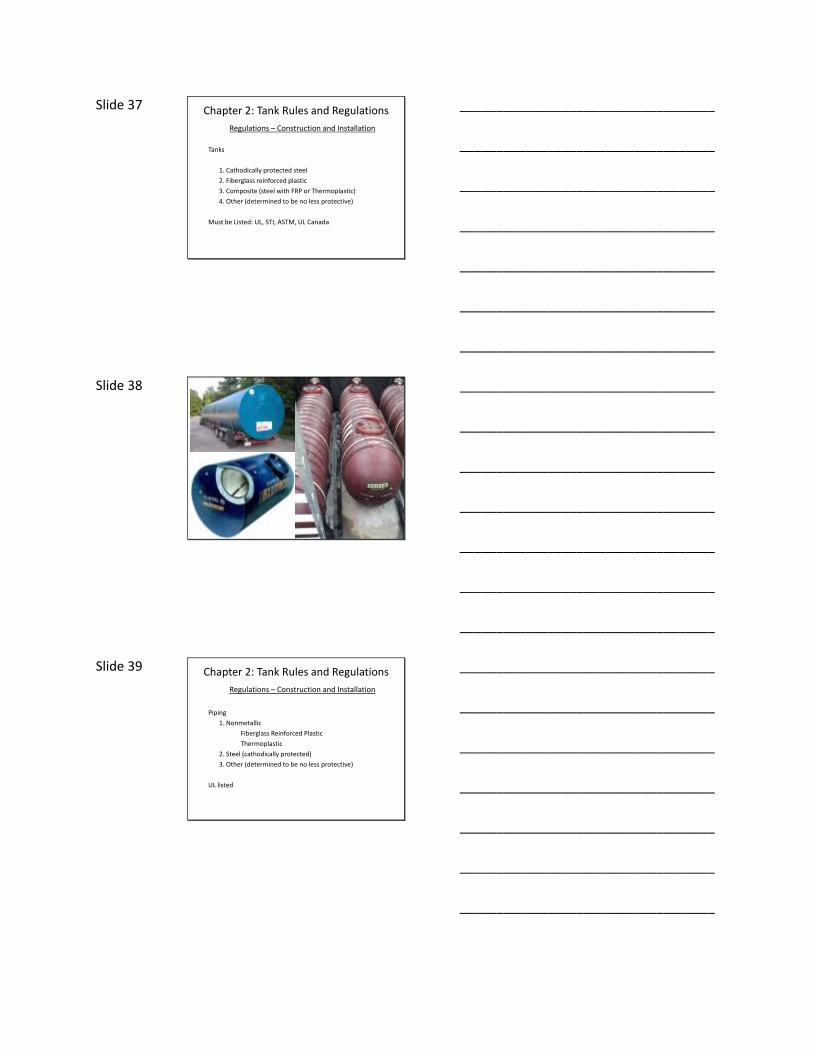
Slide 37 Chapter 2: Tank Rules and Regulations
Regulations – Construction and Installation
Tanks
1. Cathodically protected steel
2. Fiberglass reinforced plastic
3. Composite (steel with FRP or Thermoplastic)
4. Other (determined to be no less protective)
Must be Listed: UL, STI, ASTM, UL Canada
___________________________________
___________________________________
___________________________________
___________________________________
___________________________________
___________________________________
___________________________________
Slide 38
___________________________________
___________________________________
___________________________________
___________________________________
___________________________________
___________________________________
___________________________________
Slide 39 Chapter 2: Tank Rules and Regulations
Regulations – Construction and Installation
Piping
1. Nonmetallic
Fiberglass Reinforced Plastic
Thermoplastic
2. Steel (cathodically protected)
3. Other (determined to be no less protective)
UL listed
___________________________________
___________________________________
___________________________________
___________________________________
___________________________________
___________________________________
___________________________________

Slide 40
___________________________________
___________________________________
___________________________________
___________________________________
___________________________________
___________________________________
___________________________________
Slide 41 Chapter 2: Tank Rules and Regulations
Regulations – Construction and Installation
Installation
New tank and piping systems must be installed in accordance with:
1. A nationally recognized code of practice.
2. The manufacturer’s instructions.
___________________________________
___________________________________
___________________________________
___________________________________
___________________________________
___________________________________
___________________________________
Slide 42 Chapter 2: Tank Rules and Regulations
Regulations – Construction and Installation
Certification of Installation
The proposed new federal rules requires the installer to certify the installation followed the rules and industry codes.
___________________________________
___________________________________
___________________________________
___________________________________
___________________________________
___________________________________
___________________________________
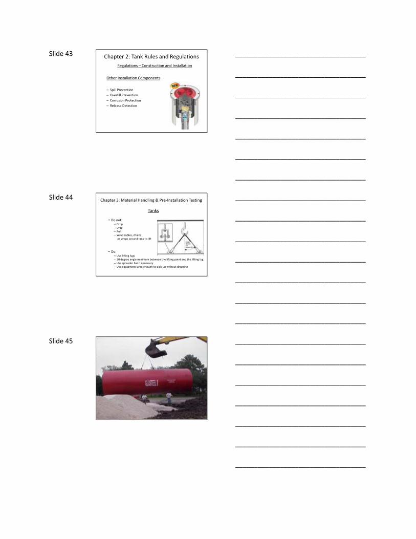
Slide 43 Chapter 2: Tank Rules and Regulations
Regulations – Construction and Installation
Other Installation Components
– Spill Prevention
– Overfill Prevention
– Corrosion Protection
– Release Detection
___________________________________
___________________________________
___________________________________
___________________________________
___________________________________
___________________________________
___________________________________
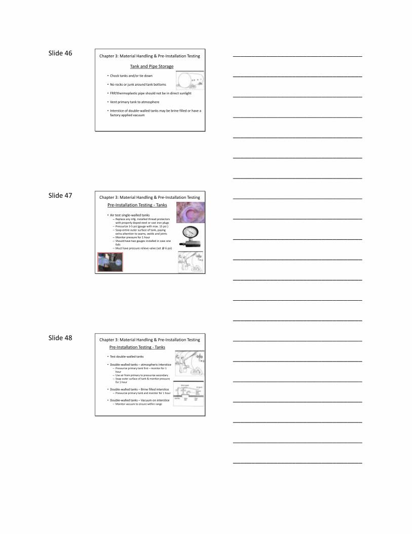
Slide 44 Chapter 3: Material Handling & Pre-Installation Testing
Tanks
• Do not:– Drop– Drag– Roll– Wrap cables, chains
or straps around tank to lift
• Do:– Use lifting lugs– 30 degree angle minimum between the lifting point and the lifting lug– Use spreader bar if necessary– Use equipment large enough to pick-up without dragging
___________________________________
___________________________________
___________________________________
___________________________________
___________________________________
___________________________________
___________________________________
Slide 45
___________________________________
___________________________________
___________________________________
___________________________________
___________________________________
___________________________________
___________________________________
Slide 46
Tank and Pipe Storage
• Chock tanks and/or tie down
• No rocks or junk around tank bottoms
• FRP/thermoplastic pipe should not be in direct sunlight
• Vent primary tank to atmosphere
• Interstice of double-walled tanks may be brine filled or have a factory applied vacuum
Chapter 3: Material Handling & Pre-Installation Testing
___________________________________
___________________________________
___________________________________
___________________________________
___________________________________
___________________________________
___________________________________
Slide 47 Chapter 3: Material Handling & Pre-Installation Testing
Pre-Installation Testing - Tanks
• Air test single-walled tanks– Replace any mfg. installed thread protectors
with properly doped steel or cast iron plugs– Pressurize 3-5 psi (gauge with max. 15 psi )– Soap entire outer surface of tank, paying
extra attention to seams, welds and joints– Monitor pressure for 1 hour– Should have two gauges installed in case one
fails– Must have pressure relieve valve (set @ 6 psi)
___________________________________
___________________________________
___________________________________
___________________________________
___________________________________
___________________________________
___________________________________
Slide 48 Chapter 3: Material Handling & Pre-Installation Testing
Pre-Installation Testing - Tanks
• Test double-walled tanks
• Double-walled tanks – atmospheric interstice– Pressurize primary tank first – monitor for 1
hour– Use air from primary to pressurize secondary– Soap outer surface of tank & monitor pressure
for 1 hour
• Double-walled tanks – Brine filled interstice– Pressurize primary tank and monitor for 1 hour
• Double-walled tanks – Vacuum on interstice– Monitor vacuum to ensure within range
___________________________________
___________________________________
___________________________________
___________________________________
___________________________________
___________________________________
___________________________________

Slide 49 Double-walled tanks -
Factory applied vacuum monitored
until backfill is complete
___________________________________
___________________________________
___________________________________
___________________________________
___________________________________
___________________________________
___________________________________
Slide 50 Chapter 3: Material Handling & Pre-Installation Testing
Pre-Installation Testing Piping
• Air test piping
– Pressurize primary pipe at 50 psi for 1 hour
– Soap entire outer surface of pipe and look for visual evidence of a leak (soap bubbles)
» 3 over 2 FRP» “Coaxial” FRP» Coaxial thermoplastic
___________________________________
___________________________________
___________________________________
___________________________________
___________________________________
___________________________________
___________________________________
Slide 51 Chapter 3: Material Handling & Pre-Installation Testing
Cold Weather Handling
• Must use heat packs if bonding FRP piping
• Thermoplastic pipe is very stiff if cold
• Water can freeze in sumps/spill buckets
___________________________________
___________________________________
___________________________________
___________________________________
___________________________________
___________________________________
___________________________________

Slide 52 Chapter 4: Excavating and Trenching
Pre-Excavation Planning
• Is there contaminated soil/groundwater?• Is there any rock to deal with?• Are there unstable soils?• What are the groundwater conditions?• Are there adjacent structures to deal with?• Where are the underground and overhead utilities?• What kind of pavement will need to be removed?• Will hold down straps be needed?• Is there anywhere to store excavated material?• Is there anywhere to store backfill material?• How close are adjoining property lines?
___________________________________
___________________________________
___________________________________
___________________________________
___________________________________
___________________________________
___________________________________
Slide 53 Chapter 4: Excavating and Trenching
Pre-Excavation Planning (cont’d)
• If there are buildings/structures at the site, the angle between the foundation of the building and the nearest edge of the bottom of the excavation must not exceed 45 degrees.
• All excavations must be at least 5 feet from adjacent structures and property lines.
___________________________________
___________________________________
___________________________________
___________________________________
___________________________________
___________________________________
___________________________________
Slide 54 Chapter 4: Excavating and Trenching
Product Delivery Truck Considerations
• Delivery points (tank fills) should be located so that the truck making the delivery will not:
– Be on a public right-of-way– Block motorists’ view of roadways– Impede flow of traffic or pedestrians
• Should also minimize the amountof maneuvering the truck must do
___________________________________
___________________________________
___________________________________
___________________________________
___________________________________
___________________________________
___________________________________

Slide 55 Chapter 4: Excavating and Trenching
Dimensions of the Excavation
• What are the manufacturers recommendations?
– Spacing between tanks– Spacing between excavation and tanks– Backfill underneath tanks– Burial depth needed for hold-down calculations– Burial depth for pipe slope– Maximum burial depth– Sloping needed to accommodate soil conditions
___________________________________
___________________________________
___________________________________
___________________________________
___________________________________
___________________________________
___________________________________
Slide 56 Chapter 4: Excavating and Trenching
Dimensions of the Excavation
• Spacing between tanks and between tanks and excavation
– PEI RP100 recommends 24 inches– API 1615 recommends 12 inches for
steel, 18 inches for FRP
• Spacing between piping within trench
– PEI RP100 recommends twice the piping diameter
• Spacing between excavation wall and pipe
– PEI RP100 recommends 6 inches
___________________________________
___________________________________
___________________________________
___________________________________
___________________________________
___________________________________
___________________________________
Slide 57 Chapter 4: Excavating and Trenching
Dimensions of the Excavation
• Depth of Excavation– Manufacturers have maximum burial depths
» Steel – Marked on the tank but usually the tank diameter» FRP – Generally 7 feet
– How much overburden is needed for hold-down?
– If piping is to be uniformly sloped, how much fall is needed?
• Bedding– Generally, 1 foot of bedding underneath tanks– If hold down pad is used – 6 inches
___________________________________
___________________________________
___________________________________
___________________________________
___________________________________
___________________________________
___________________________________

Slide 58 Chapter 4: Excavating and Trenching
Cover
• Amount of Cover Depends on:– Traffic vs. non-traffic areas– Type of pavement– Thickness of pavement– Groundwater conditions– Flood prone areas
• PEI RP100 recommends:– 30 inches backfill + 6 inches asphalt or– 18 inches backfill + 8 inches reinforced concrete
• API 1615 & NFPA 30 recommend:– 36 inches backfill or– 18 inches backfill + 8 inches asphalt / 6 inches reinforced concrete
___________________________________
___________________________________
___________________________________
___________________________________
___________________________________
___________________________________
___________________________________
Slide 59 Chapter 4: Excavating and Trenching
Sloping and Shoring
• Shoring & Sloping Requirements
– Safety of workers who must enter excavation is of primary concern
• Shoring of tank holes not usually practical or cost effective
• Sloping or benching more commonly done
• Degree of sloping depends on soil type
___________________________________
___________________________________
___________________________________
___________________________________
___________________________________
___________________________________
___________________________________
Slide 60 Chapter 4: Excavating and Trenching
Dimensions of the Excavation
• Soil Type
– Stable Rock» No sloping necessary (90 degrees)
– Type A (clay, silty/sandy clay), » 3/4 to 1 slope (53 degrees)
– Type B (silt, sandy loam)» 1 to 1 slope (45 degrees)
– Type C (sand, gravel)» 34 degrees slope
___________________________________
___________________________________
___________________________________
___________________________________
___________________________________
___________________________________
___________________________________

Slide 61 Chapter 4: Excavating and Trenching
Excavations
OSHA Requirements
• Banks more than 5 feet high must be sloped or shored
• Banks less than 5 feet must also be effectively protected if evidence of hazardous ground movement is observed
The entire depth of trenches morethan feet deep does not have to beshored – There may be 5 feet or lessat bottom of the excavation
___________________________________
___________________________________
___________________________________
___________________________________
___________________________________
___________________________________
___________________________________
Slide 62
___________________________________
___________________________________
___________________________________
___________________________________
___________________________________
___________________________________
___________________________________
Slide 63 Chapter 4: Excavating and TrenchingExcavations
OSHA Excavation Requirements
Sloping
– Slope the sides to an angle not steeper than 1 ½ to 1 (Type C soils)
– For example: For every foot of depth, the hole must be sloped back 1 ½ feet.
Benching
– No bench may have more than 5 ft vertical rise
– Benching not allowed in Type C soils
Shoring
– Trench box– Sheet piling
___________________________________
___________________________________
___________________________________
___________________________________
___________________________________
___________________________________
___________________________________
Slide 64 Chapter 4: Excavating and Trenching
Materials on Site
Stockpiling of materials
All materials must be at
least 2 feet from edge ofexcavation
___________________________________
___________________________________
___________________________________
___________________________________
___________________________________
___________________________________
___________________________________
Slide 65 Chapter 4: Excavating and Trenching
Safety Considerations
• Daily Inspections• Keep workers out from under heavy equipment• Check after rain storms• Guard against surface water and storm events (build dikes or
dig ditches)• Keep equipment away from edge• Minimize work in the excavation• Provide protective equipment• Traffic barricades• Excavation marking• Avoid hazardous areas (face of excavation)
___________________________________
___________________________________
___________________________________
___________________________________
___________________________________
___________________________________
___________________________________
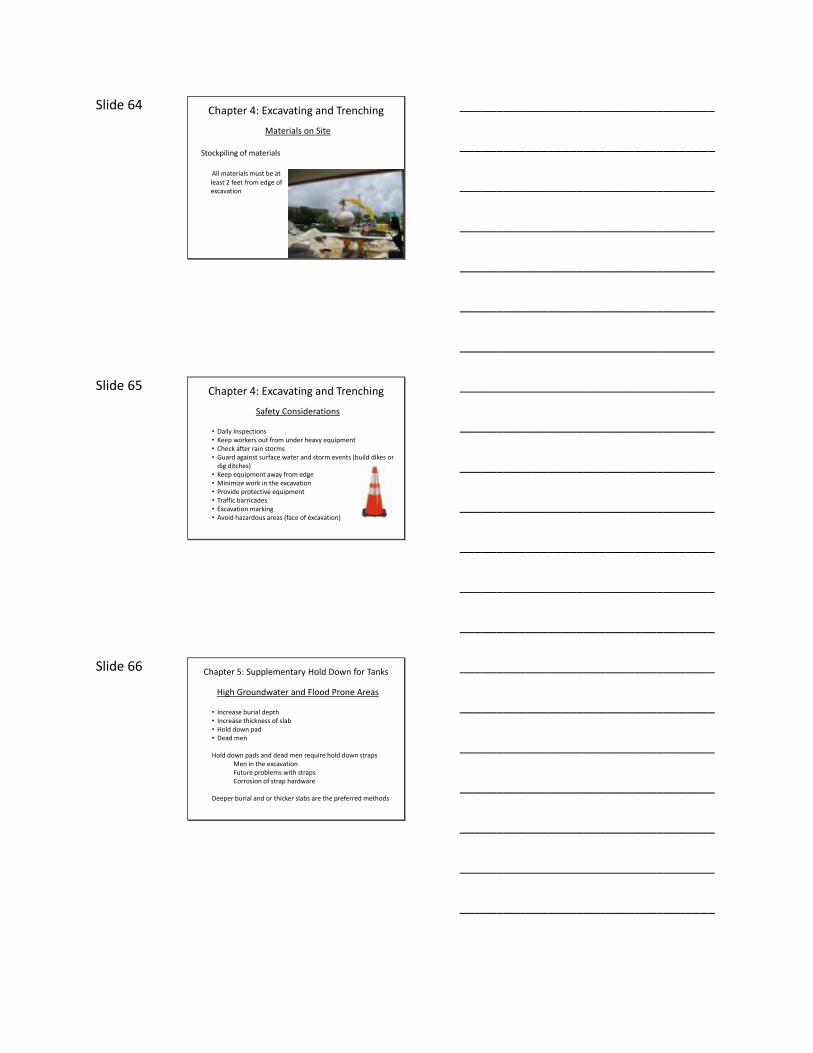
Slide 66 Chapter 5: Supplementary Hold Down for Tanks
High Groundwater and Flood Prone Areas
• Increase burial depth• Increase thickness of slab• Hold down pad• Dead men
Hold down pads and dead men require hold down strapsMen in the excavationFuture problems with strapsCorrosion of strap hardware
Deeper burial and or thicker slabs are the preferred methods
___________________________________
___________________________________
___________________________________
___________________________________
___________________________________
___________________________________
___________________________________

Slide 67 Chapter 5: Supplementary Hold Down for Tanks
High Groundwater and Flood Prone Areas
• Raise vents to be above highest anticipated flood level
• Anchor vents so that floating debris does not knock over
• Consider vapor shear valves at base of vents in case they are impacted and knocked down
Keep in mind that the greater the tank diameter the greater the buoyancy
___________________________________
___________________________________
___________________________________
___________________________________
___________________________________
___________________________________
___________________________________
Slide 68 Chapter 5: Supplementary Hold Down for Tanks
Wet Hole Conditions
Water should be pumped out when setting tanks
If not possible, water ballast tanks to sink them
Water in tank must not exceed water level in hole
Lifting equipment may be used to stabilize the tank but no pressure on the lifting cables can occur or the tank may be damaged
___________________________________
___________________________________
___________________________________
___________________________________
___________________________________
___________________________________
___________________________________
Slide 69 Chapter 5: Supplementary Hold Down for Tanks
Dewatering
• Dewatering
– Vacuum Trucks– Well Pointing– “Dipping”
___________________________________
___________________________________
___________________________________
___________________________________
___________________________________
___________________________________
___________________________________
Slide 70 Chapter 5: Supplementary Hold Down for Tanks
Bottom Hold Down Pad
• “Normal” pad is eight inches thick (exact thickness calculated)• Extends 18 inches beyond sides of tanks• Extends 12 inches beyond ends of tanks
Excess dimensions provide stable base for entire tank and increase hold down force by allowing full weight of backfill column to act on pad
___________________________________
___________________________________
___________________________________
___________________________________
___________________________________
___________________________________
___________________________________
Slide 71 Chapter 5: Supplementary Hold Down for Tanks
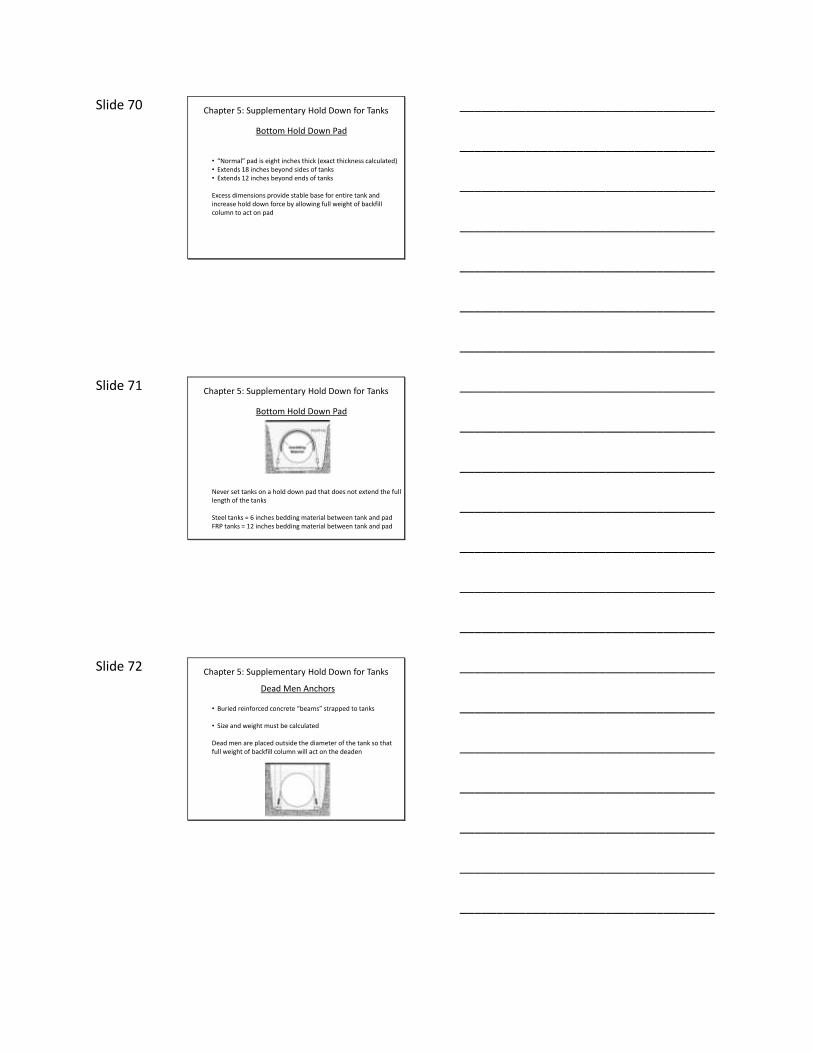
Bottom Hold Down Pad
Never set tanks on a hold down pad that does not extend the full length of the tanks
Steel tanks = 6 inches bedding material between tank and padFRP tanks = 12 inches bedding material between tank and pad
___________________________________
___________________________________
___________________________________
___________________________________
___________________________________
___________________________________
___________________________________
Slide 72 Chapter 5: Supplementary Hold Down for Tanks
Dead Men Anchors
• Buried reinforced concrete “beams” strapped to tanks
• Size and weight must be calculated
Dead men are placed outside the diameter of the tank so that full weight of backfill column will act on the deaden
___________________________________
___________________________________
___________________________________
___________________________________
___________________________________
___________________________________
___________________________________

Slide 73
___________________________________
___________________________________
___________________________________
___________________________________
___________________________________
___________________________________
___________________________________
Slide 74 Chapter 5: Supplementary Hold Down for Tanks
Hold Down Straps
• Are supplied by the tank manufacturer• Installation position is specified by manufacturer• Are typically made of nonmetallic material• Turnbuckles generally employed to adjust tension• Metal connections, turnbuckles subject to corrosion
– Must be coated with dielectric material– Should consider installation of sacrificial anodes
___________________________________
___________________________________
___________________________________
___________________________________
___________________________________
___________________________________
___________________________________
Slide 75 Chapter 5: Supplementary Hold Down for Tanks
Calculating Hold Down Requirements
• Must first determine buoyant forces in order to calculate hold down needed to ensure tank does not float.
• The buoyant upward force of a tank is directly related to the amount of water it displaces.
• This means that the weight of the water the tank displaces must be calculated.
___________________________________
___________________________________
___________________________________
___________________________________
___________________________________
___________________________________
___________________________________
Slide 76 Chapter 5: Supplementary Hold Down for Tanks
___________________________________
___________________________________
___________________________________
___________________________________
___________________________________
___________________________________
___________________________________
Slide 77 Chapter 5: Supplementary Hold Down for Tanks
___________________________________
___________________________________
___________________________________
___________________________________
___________________________________
___________________________________
___________________________________
Slide 78 Chapter 5: Supplementary Hold Down for Tanks
Calculating Hold Down Requirements
Volume = 1356.48 ft3
This gives us the volume of water displaced but we need to know the weight of the water (water = 62.4 lb/ft3)
To calculate the weight of the displaced water multiply volume (calculated in ft3) by 62.4 lb/ft3
1356.48 ft3 x 62.4 lb/ft3 = 84,645 lb
The weight needed on top of the tank to offset the buoyant forces is rounded up to equal 85,000 lb
___________________________________
___________________________________
___________________________________
___________________________________
___________________________________
___________________________________
___________________________________
Slide 79 Chapter 5: Supplementary Hold Down for Tanks
Calculating Hold Down Requirements
Calculation of total tank volume is not as simple as this example – Other aspects of the tank must be considered:
• Man ways• Interstice of double-walled tanks• Ribs (FRP tanks)• Convex end caps (FRP tanks)• Risers
• Formula for a cylinder is a rough estimate – Consult with the manufacturer to determine total displacement of the tank, including appurtenances and multiply this by 62.4 lbs.
___________________________________
___________________________________
___________________________________
___________________________________
___________________________________
___________________________________
___________________________________
Slide 80 Chapter 5: Supplementary Hold Down for Tanks
Calculating Hold Down Requirements
Weight Calculations
• First, you must figure in the weight of the tank and all appurtenances themselves.
• Convex end caps (FRP tanks)
• Risers
• Formula for a cylinder is a rough estimate – Consult with the manufacturer to determine total displacement of the tank, including appurtenances and multiply this by 62.4 lbs.
___________________________________
___________________________________
___________________________________
___________________________________
___________________________________
___________________________________
___________________________________
Slide 81 Chapter 5: Supplementary Hold Down for Tanks
Calculating Hold Down Requirements
Weight Calculations
• When calculating weight of backfill, keep in mind that you must figure submerged weight – Not dry weight.
• A cubic foot of sand or pea gravel submerged in water does not weigh as much as the same cubic foot of sand or pea gravel when it is dry.
• Submerged weights must be figured for everything (tanks, backfill, slab) when making calculations.
___________________________________
___________________________________
___________________________________
___________________________________
___________________________________
___________________________________
___________________________________

Slide 82 Chapter 5: Supplementary Hold Down for Tanks
Calculating Hold Down Requirements
Tank Slab Area
• It is accepted practice that the slab extends 1 foot beyond the dimensions of the tank.
• In our example of a 10,000 gallon steel tank that is 8’ x 27’ the slab would be 10 feet wide x 29 feet long.
10 x 29 = 290 square feet
This is the actual figure (instead of the tank reflected area) that is used when calculating the weight of the overburden that is
acting downward on the tank.
___________________________________
___________________________________
___________________________________
___________________________________
___________________________________
___________________________________
___________________________________
Slide 83 Chapter 5: Supplementary Hold Down for Tanks
Calculating Hold Down Requirements
Determining Total Downward Force
• After you have figured the total buoyant force (weight of displaced water) and the tank slab area (square feet), you can now calculate the total amount of overburden weight necessary to prevent the tank from float out.
___________________________________
___________________________________
___________________________________
___________________________________
___________________________________
___________________________________
___________________________________
Slide 84 Chapter 5: Supplementary Hold Down for Tanks
Calculating Hold Down Requirements
Determining Total Downward Force
Determined that total weight needed = 85,000 pounds
• Weight of tank itself = 8000 lbs
• Weight of slab=
8 inch slab of 290 ft2 = volume of 218 ft3
Submerged weight of reinforced concrete = 87.6 lbs/ft3
218 x 87.6 = 19,097 lbs.
• 8000 + 19,100 = 27,100 lbs (weight of tank + slab)
___________________________________
___________________________________
___________________________________
___________________________________
___________________________________
___________________________________
___________________________________

Slide 85 Chapter 5: Supplementary Hold Down for Tanks
Calculating Hold Down Requirements
Determining Total Downward Force
Determined that total weight needed = 85,000 pounds
• 85,000 – 27,100 = 57,900 lb backfill needed to achieve total
Volume of backfill needed =
57,900 ÷ 60 (submerged wt. of sand) = 965 ft3
965 ÷ 290 = 3.33 feet
___________________________________
___________________________________
___________________________________
___________________________________
___________________________________
___________________________________
___________________________________
Slide 86 Chapter 5: Supplementary Hold Down for Tanks
Calculating Hold Down Requirements
Appendix of PEI RP100 is the best reference for hold down calculation.
___________________________________
___________________________________
___________________________________
___________________________________
___________________________________
___________________________________
___________________________________
Slide 87 Chapter 6: Backfill and Compaction
– Follow the manufacturers instructions regarding the type of backfill.
– Generally, clean sand or pea gravel / crushed stone is used for backfill. Rarely (if ever) is it appropriate to use native soil.
– Whatever is used, uniformity is critical (no rocks, chunks or foreign objects).
___________________________________
___________________________________
___________________________________
___________________________________
___________________________________
___________________________________
___________________________________

Slide 88 Chapter 6: Backfill and Compaction
– Very important to ensure tank lower quadrant is properly compacted
• May use long handled probes to accomplish this
___________________________________
___________________________________
___________________________________
___________________________________
___________________________________
___________________________________
___________________________________
Slide 89 Chapter 6: Backfill and Compaction
General Rules of Thumb
– Sand: Clean and uniform (no more than 3% pass through #8 sieve), well granulated and free flowing
– Pea Gravel: 1/8 to 3/4 inch
– Crushed Stone: 1/4 to 1/2 inch
___________________________________
___________________________________
___________________________________
___________________________________
___________________________________
___________________________________
___________________________________
Slide 90 Chapter 6: Backfill and Compaction
General Rules of Thumb
– Steel/Composite Tanks: Sand, pea gravel, crushed stone
– FRP Tanks: Pea gravel, crushed stone (sand in some circumstances)
– Piping: Sand, pea gravel, crushed stone
___________________________________
___________________________________
___________________________________
___________________________________
___________________________________
___________________________________
___________________________________

Slide 91 Chapter 6: Backfill and Compaction
Bedding & Placement
– Bottom of Excavation – Place 12 inches of backfill in bottom before setting tanks.
• If using a hold down pad may reduce to 6 inches for steel/composite tanks (FRP still 12 inches).
– Backfill should extend 2 feet from ends and sides of tanks (1 foot per API 1615)
– At least 2 feet of backfill over tanks
___________________________________
___________________________________
___________________________________
___________________________________
___________________________________
___________________________________
___________________________________
Slide 92 Chapter 6: Backfill and Compaction
Compaction
– USTs depend on properly compacted backfill for structural support – tanks are not designed to be “self supporting”
– Bottom quadrants of tanks must be hand tamped to ensure proper backfilling/compaction in this area.
– Sand must be mechanically compacted.
– Pea gravel/crushed stone generally self-compacting.
– Add backfill in 12 inch lifts.
– Do not use water to facilitate compaction.
___________________________________
___________________________________
___________________________________
___________________________________
___________________________________
___________________________________
___________________________________
Slide 93 Chapter 6: Backfill and Compaction
Ballasting
– Do not ballast until backfilled to the top of tank.• It is possible to partially ballast as long as ballast level does
not exceed the backfill level – May be necessary to “sink” tank in a flooded hole
– Water is generally preferred rather thanproduct but both have their advantages/disadvantages.
___________________________________
___________________________________
___________________________________
___________________________________
___________________________________
___________________________________
___________________________________

Slide 94 Chapter 6: Backfill and Compaction
Ballasting
– Water• What about disposal when it comes time to put into service?• Could allow growth of microbes inside tank (slimy)• Can’t install STP or other in-tank electronic equipment.
– Product• Fire codes may prohibit• Can’t do air testing on tank• If something does go wrong……• Ethanol fuels have relatively short “shelf life”• Product is lighter than water
___________________________________
___________________________________
___________________________________
___________________________________
___________________________________
___________________________________
___________________________________
Slide 95 Chapter 6: Backfill and Compaction
Backfill Migration
– Occurs when two distinctly different materials are in contact with one another underground
• Over time, the material that has the higher density (backfill) will migrate into the material (native soil) that has the lower density.
• The same thing happens when two different types of backfill are used in the same excavation (e.g. pea gravel around tanks and “topping off” with sand).
___________________________________
___________________________________
___________________________________
___________________________________
___________________________________
___________________________________
___________________________________
Slide 96 Chapter 6: Backfill and Compaction
Backfill Migration
– Filter fabrics are installed to prevent backfill migration
___________________________________
___________________________________
___________________________________
___________________________________
___________________________________
___________________________________
___________________________________

Slide 97 Chapter 6: Backfill and Compaction
Tank Deflection
– Minor “breathing” of tanks is normal. • Tanks will “squat” or “stand up” slightly depending on
relationship of product level inside tank to groundwater conditions and variations between them.
– Excessive deformation can cause trouble• Tank diameter is measured before and at various stages of
installation process.– While still above ground– After placing in excavation but before backfilling begins– After backfilling to the top of the tank
___________________________________
___________________________________
___________________________________
___________________________________
___________________________________
___________________________________
___________________________________
Slide 98 Chapter 6: Backfill and Compaction
Tank Deflection
– The cause of excessive tank deflection is usually inadequate backfill compaction
• Directly underneath tank• At the lower quadrants of the tank• At the sides of the tank
– Excessive deflection must be addressed before proceeding – can cause stress cracking of the tank shell that can lead to failure
– Retain deflection testing records in installation documents (tank installation checklist)
___________________________________
___________________________________
___________________________________
___________________________________
___________________________________
___________________________________
___________________________________
Slide 99 Chapter 6: Backfill and Compaction
Backfilling of Piping Trenches
– The backfill requirements for piping are generally the same as for tanks (sand, pea gravel or crushed stone).
– Trenches should be deep enough to allow for 6 inches of backfill beneath the pipe and at least 18 inches of backfill on top of the pipe.
– Trenches should be wide enough to allow separation distances of twice the pipe diameter between any two pipes and 6 inches betweenthe trench side and the pipe.
___________________________________
___________________________________
___________________________________
___________________________________
___________________________________
___________________________________
___________________________________

Slide 100 Chapter 6: Backfill and Compaction
Backfilling of Piping Trenches
– Nonmetallic piping should be marked with magnetic tape or a tracer wire so that the line can be located in the future.
• Tracer wires must be accessible at both the STP end and the furthest dispenser.
___________________________________
___________________________________
___________________________________
___________________________________
___________________________________
___________________________________
___________________________________
Slide 101 Chapter 6: Backfill and Compaction
Final Grading & Paving
– The paving over the tanks in traffic areas must extend at least one foot (12 inches) beyond the area of the tanks in all directions.
– To prevent damage to the piping by electrical contractors and/or pavers,clearly mark piping trenches.
– Many contractors leave 50 psi on the piping until final concrete work is completed.
___________________________________
___________________________________
___________________________________
___________________________________
___________________________________
___________________________________
___________________________________
Slide 102 Chapter 7: Secondary Containment & Spill/Overfill Prevention
Overfill Prevention
Not required if filled by transfers of no more than 25 gallons
Options in 40 CFR 280
1. Automatically shut off flow when the tank is no more than @ 95% full
2. Alert the transfer operator when the tank is no more than 90% full by:a. restricting flowb. triggering an alarm
___________________________________
___________________________________
___________________________________
___________________________________
___________________________________
___________________________________
___________________________________

Slide 103 Chapter 7: Secondary Containment & Spill/Overfill Prevention
Overfill Prevention
Other options added when 40 CFR 280 amended in 1991
1. Restrict flow 30 minutes prior to overfilling.
2. Alert the operator with a high level alarm one minute before overfilling.
3. Automatically shut off flow into the tank so that none of the fittings located on top of the tank are exposed to product.
___________________________________
___________________________________
___________________________________
___________________________________
___________________________________
___________________________________
___________________________________
Slide 104 Chapter 7: Secondary Containment & Spill/Overfill Prevention
Overfill Prevention
1. Shut off (95%)• Drop tube device
2. Restrict (90%)• Ball Float Valve
3. Alarm (90%)• Electronic Alarm
___________________________________
___________________________________
___________________________________
___________________________________
___________________________________
___________________________________
___________________________________
Slide 105 OVERFILL PREVENTION DEVICES
RESTRICT ALARM SHUT OFF
___________________________________
___________________________________
___________________________________
___________________________________
___________________________________
___________________________________
___________________________________

Slide 106
ARE WE EFFECTIVELY PREVENTING OVERFILLS?
Chapter 7: Secondary Containment & Spill/Overfill Prevention
___________________________________
___________________________________
___________________________________
___________________________________
___________________________________
___________________________________
___________________________________
Slide 107
SHUT OFF
To stop the flow or passage of; cut off
Generally thought of as 95% tank capacity
– Alternative rule allows filling beyond 95% as long as tank top fittings are not wetted.
Chapter 7: Secondary Containment & Spill/Overfill Prevention
___________________________________
___________________________________
___________________________________
___________________________________
___________________________________
___________________________________
___________________________________
Slide 108 95% SHUT OFF
DEVICE
___________________________________
___________________________________
___________________________________
___________________________________
___________________________________
___________________________________
___________________________________

Slide 109
SHUT OFF
• Certain devices are marketed as providing precision repeatability - allowing tank to be filled up to 99% capacity– 99% capacity is taken to represent the maximum
allowable fill level that will satisfy the alternate rule requirements that no tank top fittings are wetted
Chapter 7: Secondary Containment & Spill/Overfill Prevention
___________________________________
___________________________________
___________________________________
___________________________________
___________________________________
___________________________________
___________________________________
Slide 110
___________________________________
___________________________________
___________________________________
___________________________________
___________________________________
___________________________________
___________________________________
Slide 111
99% SHUT OFF DEVICE
___________________________________
___________________________________
___________________________________
___________________________________
___________________________________
___________________________________
___________________________________

Slide 112
HOW DO DROP TUBE DEVICES WORK?
All of these function as “two point” shut off devices
Initially, flow is restricted (point 1)
Subsequently, flow is shut off (point 2)
Some devices do this with one float, others two floats
Some devices do this with one valve. others two valves
• Chapter 7: Secondary Containment & Spill/Overfill Prevention
___________________________________
___________________________________
___________________________________
___________________________________
___________________________________
___________________________________
___________________________________
Slide 113
HOW DO DROP TUBE DEVICES WORK?
1st Stage “shut off” intended to relieve hydraulic shock should 2nd stage shut off occur
No manufacturer recognizes these as restriction devices – Shut off devices only
• Chapter 7: Secondary Containment & Spill/Overfill Prevention
___________________________________
___________________________________
___________________________________
___________________________________
___________________________________
___________________________________
___________________________________
Slide 114 Reason for Two Stage Shutoff - Hydraulic Hammer
Tremendous stress placed on delivery
system when 400 gpm flow rate is suddenly
interrupted
• Chapter 7: Secondary Containment & Spill/Overfill Prevention
___________________________________
___________________________________
___________________________________
___________________________________
___________________________________
___________________________________
___________________________________

Slide 115
___________________________________
___________________________________
___________________________________
___________________________________
___________________________________
___________________________________
___________________________________
Slide 116
___________________________________
___________________________________
___________________________________
___________________________________
___________________________________
___________________________________
___________________________________
Slide 117 SOME HAVE MINIMUM CLEARANCE REQURIEMENTS
Chapter 7: Secondary Containment & Spill/Overfill Prevention
___________________________________
___________________________________
___________________________________
___________________________________
___________________________________
___________________________________
___________________________________

Slide 118
CROWED SUMPS ARE IN VOGUE
• Chapter 7: Secondary Containment & Spill/Overfill Prevention
___________________________________
___________________________________
___________________________________
___________________________________
___________________________________
___________________________________
___________________________________
Slide 119
DROP TUBE SHUT OFF DEVICES4 U.S. Manufacturers
Universal
Model 39EBW
Auto Limiter II
Emco Wheaton
Guardian A1100
OPW
61-SO / 71-SO
Chapter 7: Secondary Containment & Spill/Overfill Prevention
___________________________________
___________________________________
___________________________________
___________________________________
___________________________________
___________________________________
___________________________________
Slide 120
Manufacturers give “standard” installation instructions
PEI RP-100 requires that these devices must be installed according to the manufacturers instructions
Chapter 7: Secondary Containment & Spill/Overfill Prevention
___________________________________
___________________________________
___________________________________
___________________________________
___________________________________
___________________________________
___________________________________
Slide 121
Where these devices actually shut off depends on where the installer actually cuts the drop tube and several other factors
- specific gravity
- tank deflection
- tank tilt
• Chapter 7: Secondary Containment & Spill/Overfill Prevention
___________________________________
___________________________________
___________________________________
___________________________________
___________________________________
___________________________________
___________________________________
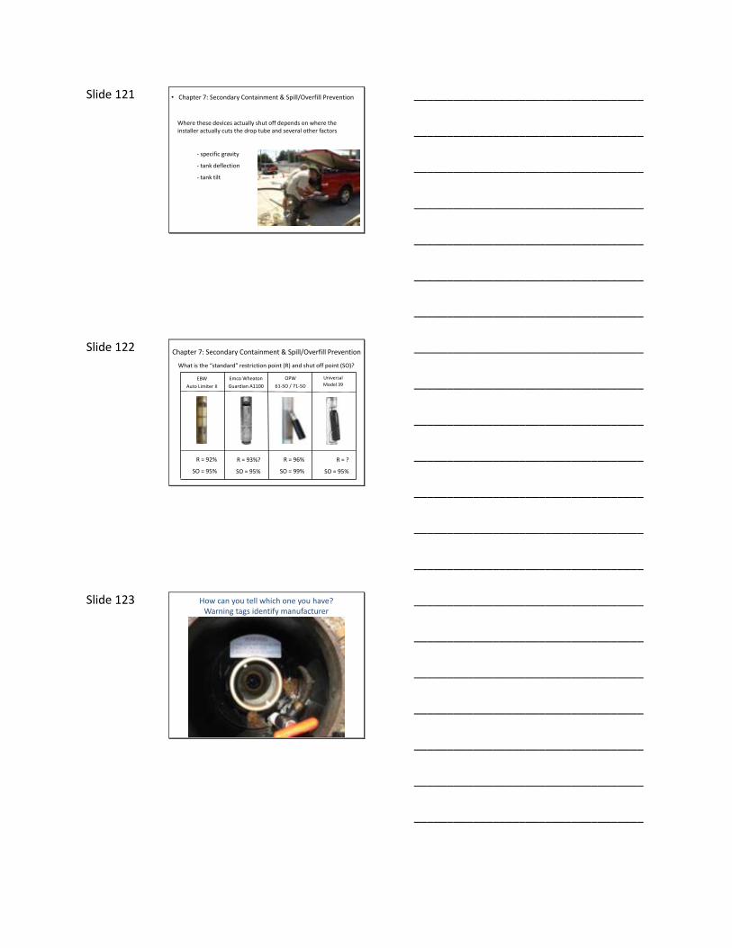
Slide 122 What is the “standard” restriction point (R) and shut off point (SO)?
Universal
Model 39EBW
Auto Limiter II
Emco Wheaton
Guardian A1100
OPW
61-SO / 71-SO
R = 92%
SO = 95%
R = 93%?
SO = 95%
R = 96%
SO = 99%
R = ?
SO = 95%
Chapter 7: Secondary Containment & Spill/Overfill Prevention
___________________________________
___________________________________
___________________________________
___________________________________
___________________________________
___________________________________
___________________________________
Slide 123 How can you tell which one you have?Warning tags identify manufacturer
___________________________________
___________________________________
___________________________________
___________________________________
___________________________________
___________________________________
___________________________________
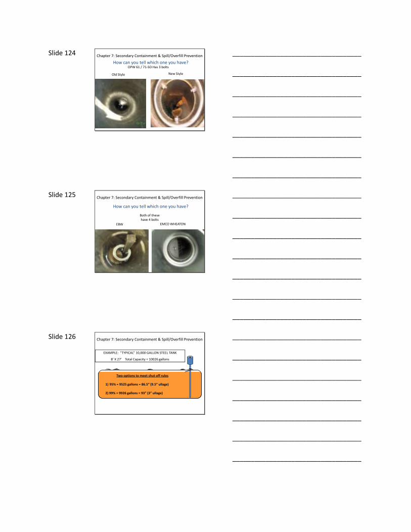
Slide 124 How can you tell which one you have?
OPW 61 / 71-SO Has 3 bolts
Old Style New Style
Chapter 7: Secondary Containment & Spill/Overfill Prevention
___________________________________
___________________________________
___________________________________
___________________________________
___________________________________
___________________________________
___________________________________
Slide 125
How can you tell which one you have?
EBW EMCO WHEATON
Both of these have 4 bolts
Chapter 7: Secondary Containment & Spill/Overfill Prevention
___________________________________
___________________________________
___________________________________
___________________________________
___________________________________
___________________________________
___________________________________
Slide 126
EXAMPLE: “TYPICAL” 10,000 GALLON STEEL TANK
8’ X 27’ Total Capacity = 10026 gallons
Two options to meet shut off rules
1) 95% = 9525 gallons = 86.5” (9.5” ullage)
2) 99% = 9926 gallons = 93” (3” ullage)
Chapter 7: Secondary Containment & Spill/Overfill Prevention
___________________________________
___________________________________
___________________________________
___________________________________
___________________________________
___________________________________
___________________________________

Slide 127
Two options to meet shut off rules
1) 95% = 9525 gallons = 86.5” (9.5” ullage)
2) 99% = 9926 gallons = 93” (3” ullage)
EXAMPLE: “TYPICAL” 10,000 GALLON STEEL TANK
8’ X 27’ Total Capacity = 10026 gallons
Chapter 7: Secondary Containment & Spill/Overfill Prevention
___________________________________
___________________________________
___________________________________
___________________________________
___________________________________
___________________________________
___________________________________
Slide 128
“STANDARD” INSTALLATION INSTRUCTIONS
Chapter 7: Secondary Containment & Spill/Overfill Prevention
___________________________________
___________________________________
___________________________________
___________________________________
___________________________________
___________________________________
___________________________________
Slide 129
GENERAL INSTRUCTIONS
The main 61SO valve normally closes when liquid level is within 8” of the top of the tank. (The actual shut-off points are a function of where the valve is positioned in the tank, which is determined by the length of the upper tube). A small bypass valve remains open to allow the delivery hose to drain at 5 gallons per minute. If the delivery truck valve is not closed after initial shut-off, the bypass valve will close when the liquid level is within 3” of the top of the tank.
3 inches ullage = 99% capacity
Chapter 7: Secondary Containment & Spill/Overfill Prevention
___________________________________
___________________________________
___________________________________
___________________________________
___________________________________
___________________________________
___________________________________

Slide 130
Does this meet the overfill prevention requirements?
A. 95% - NO
B. 99% - YES
Tank is perfectly level
Shuts Off @ “Standard” 3 Inches
Chapter 7: Secondary Containment & Spill/Overfill Prevention
___________________________________
___________________________________
___________________________________
___________________________________
___________________________________
___________________________________
___________________________________
Slide 131
Overfill device installed on the low end of the tank
What if the tank is tilted?
“Positive Tilt”
Chapter 7: Secondary Containment & Spill/Overfill Prevention
___________________________________
___________________________________
___________________________________
___________________________________
___________________________________
___________________________________
___________________________________
Slide 132
What if the tank is tilted?
Overfill device installed on the high end of the tank
“Negative Tilt”
Chapter 7: Secondary Containment & Spill/Overfill Prevention
___________________________________
___________________________________
___________________________________
___________________________________
___________________________________
___________________________________
___________________________________
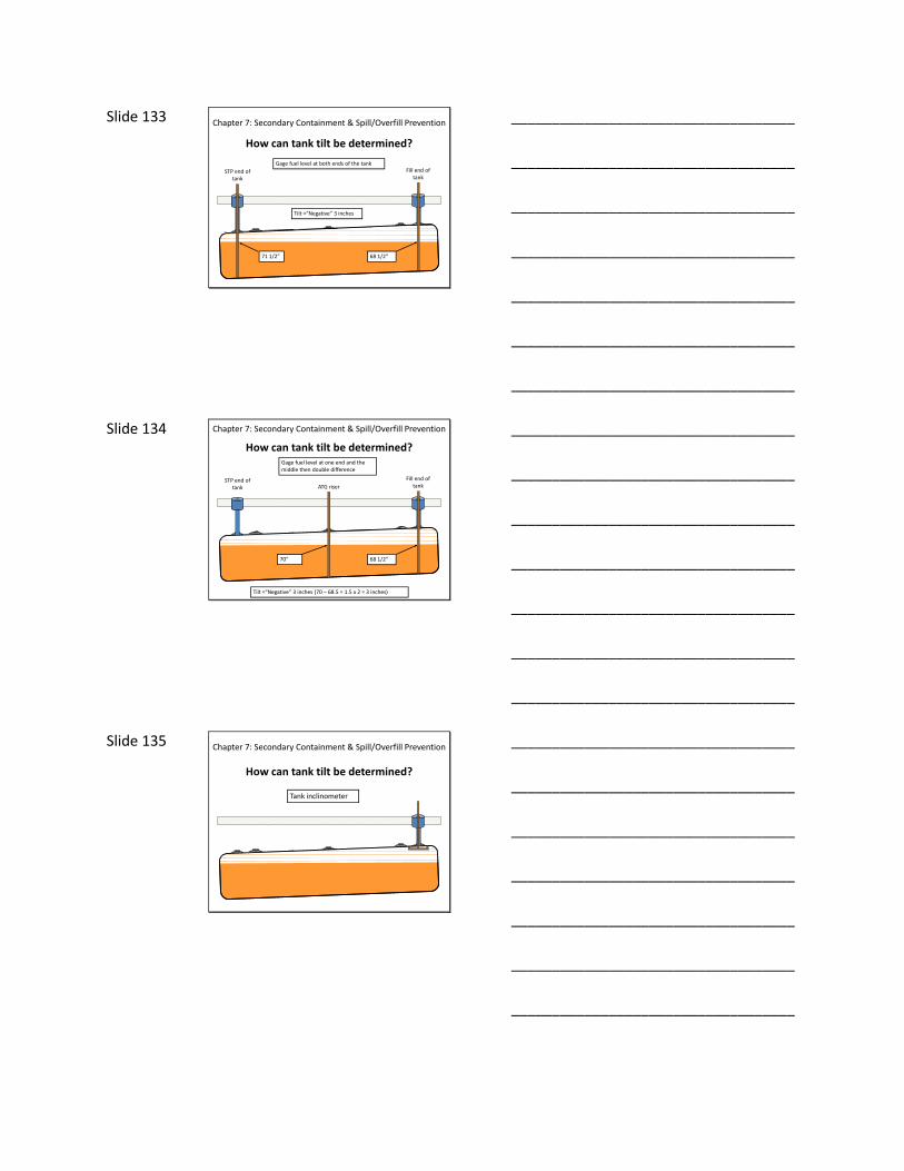
Slide 133
How can tank tilt be determined?
71 1/2” 68 1/2”
Tilt =“Negative” 3 inches
STP end of tank
Fill end of tank
Gage fuel level at both ends of the tank
Chapter 7: Secondary Containment & Spill/Overfill Prevention
___________________________________
___________________________________
___________________________________
___________________________________
___________________________________
___________________________________
___________________________________
Slide 134 How can tank tilt be determined?
70” 68 1/2”
Tilt =“Negative” 3 inches (70 – 68.5 = 1.5 x 2 = 3 inches)
ATG riser
Fill end of tank
STP end of tank
Gage fuel level at one end and the middle then double difference
Chapter 7: Secondary Containment & Spill/Overfill Prevention
___________________________________
___________________________________
___________________________________
___________________________________
___________________________________
___________________________________
___________________________________
Slide 135
How can tank tilt be determined?
Tank inclinometer
Chapter 7: Secondary Containment & Spill/Overfill Prevention
___________________________________
___________________________________
___________________________________
___________________________________
___________________________________
___________________________________
___________________________________

Slide 136
How can tank tilt be determined?
Transit Level
Chapter 7: Secondary Containment & Spill/Overfill Prevention
___________________________________
___________________________________
___________________________________
___________________________________
___________________________________
___________________________________
___________________________________
Slide 137
Shuts off @ “standard” 3 inches
Does this tank meet overfill prevention requirements?
A. 95% - NO
B. 99% – NO (ullage is less than 1% capacity)
1 inch Negative Tilt
DEVICE INSTALLED AT HIGH END OF TANK 3”2”
Chapter 7: Secondary Containment & Spill/Overfill Prevention
___________________________________
___________________________________
___________________________________
___________________________________
___________________________________
___________________________________
___________________________________
Slide 138
Shuts off @ “standard” 3 inches
Potential for Hidden Overfill to Occur
3 inches Negative Tilt
DEVICE INSTALLED AT HIGH END OF TANK 3”
Chapter 7: Secondary Containment & Spill/Overfill Prevention
___________________________________
___________________________________
___________________________________
___________________________________
___________________________________
___________________________________
___________________________________

Slide 139
What About Secondarily Contained Tanks?
Double-walled tank
8 foot diameter
300 degree wrap
Should overfill prevention requirements consider
single-walled portion of secondarily contained
tanks?
300 degree wrap = 6 inches ullage
Chapter 7: Secondary Containment & Spill/Overfill Prevention
___________________________________
___________________________________
___________________________________
___________________________________
___________________________________
___________________________________
___________________________________
Slide 140
Overfill Prevention Device Shuts off @ 3 inches
3” 6”
Does this meet the overfill prevention requirements?
Yes?
Does this meet the secondary containment
requirements?
No?
Double-walled tank
8 foot diameter
300 degree wrap
Chapter 7: Secondary Containment & Spill/Overfill Prevention
___________________________________
___________________________________
___________________________________
___________________________________
___________________________________
___________________________________
___________________________________
Slide 141
OTHER POTENTIAL ISSUES
• Aluminum compatibility with ethanol
• Long term performance of elastomeric seals
– Compatibility
– Mechanical Wear
• Effectiveness of 100% shutoff is questionable
Chapter 7: Secondary Containment & Spill/Overfill Prevention
___________________________________
___________________________________
___________________________________
___________________________________
___________________________________
___________________________________
___________________________________
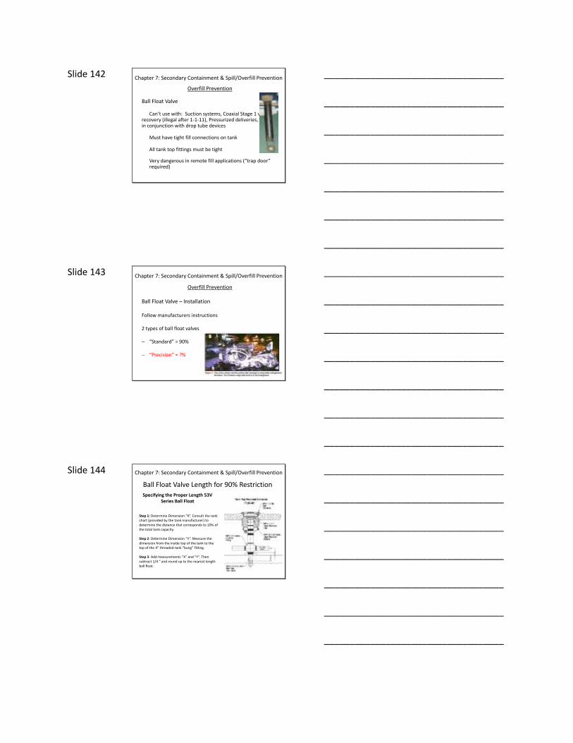
Slide 142 Chapter 7: Secondary Containment & Spill/Overfill Prevention
Overfill Prevention
Ball Float Valve
Can’t use with: Suction systems, Coaxial Stage 1 vapor recovery (illegal after 1-1-11), Pressurized deliveries, in conjunction with drop tube devices
Must have tight fill connections on tank
All tank top fittings must be tight
Very dangerous in remote fill applications (“trap door” required)
___________________________________
___________________________________
___________________________________
___________________________________
___________________________________
___________________________________
___________________________________
Slide 143 Chapter 7: Secondary Containment & Spill/Overfill Prevention
Overfill Prevention
Ball Float Valve – Installation
Follow manufacturers instructions
2 types of ball float valves
– “Standard” = 90%
– “Precision” = ?%
___________________________________
___________________________________
___________________________________
___________________________________
___________________________________
___________________________________
___________________________________
Slide 144
Specifying the Proper Length 53V Series Ball Float
Step 1: Determine Dimension “X”. Consult the tank chart (provided by the tank manufacturer) to determine the distance that corresponds to 10% of the total tank capacity.
Step 2: Determine Dimension “Y”. Measure the dimension from the inside top of the tank to the top of the 4” threaded tank “bung” fitting.
Step 3: Add measurements “X” and “Y”. Then subtract 1/4 “ and round up to the nearest length ball float.
Ball Float Valve Length for 90% Restriction
Chapter 7: Secondary Containment & Spill/Overfill Prevention
___________________________________
___________________________________
___________________________________
___________________________________
___________________________________
___________________________________
___________________________________

Slide 145
DEPTH (inches) GALLONS78 8701.9 79 8804.3 80 8904.4 81 9002.0 82 9097.0 83 9189.2 84 9278.4 85 9364.6 86 9447.3 87 9526.5 88 9601.9 89 9673.0 90 9739.7 91 9801.3 92 9857.3 93 9907.0 94 9949.2 95 9981.9 96 10,000
Step 1: “X” = 10% tank capacity
96” – 81” = 15”
Step 2: “Y” = 1 inch
Step 3: “X” + “Y” - 1/4“ = ball float length
15” + 1” = 16” - 1/4“ = 15 3/4”
Ball float length = 16”
8’ Diameter Tank
Ball Float Valve Length for 90% Restriction
Chapter 7: Secondary Containment & Spill/Overfill Prevention
___________________________________
___________________________________
___________________________________
___________________________________
___________________________________
___________________________________
___________________________________
Slide 146
Ball Float Valve Length for 90% Restriction
The length of the ball float valve depends only on the diameter of the tank – The tank capacity does not matter.
Chapter 7: Secondary Containment & Spill/Overfill Prevention
___________________________________
___________________________________
___________________________________
___________________________________
___________________________________
___________________________________
___________________________________
Slide 147
DEPTH (inches) GALLONS78 8701.9 79 8804.3 80 8904.4 81 9002.0 82 9097.0 83 9189.2 84 9278.4 85 9364.6 86 9447.3 87 9526.5 88 9601.9 89 9673.0 90 9739.7 91 9801.3 92 9857.3 93 9907.0 94 9949.2 95 9981.9 96 10,000
8’ Diameter Tank
To begin restricting flow 30 minutes prior to overfilling
Follow the steps as outlined above, except the length of the float vent valve must be determined using the UST’s tank chart in lieu of the Float Vent Valve Sizing Chart shown above. From the UST tank chart, determine the length which corresponds to 310 gallons. Use this figure for the length of the green pipe.
96” – 89” = 7”
310 gal. ÷ 30 min. = 10.3 gal/min
Ball Float Valve Length for 30 Minute Restriction
___________________________________
___________________________________
___________________________________
___________________________________
___________________________________
___________________________________
___________________________________

Slide 148 Ball Float Valve Length for 30 Minute Restriction
Chapter 7: Secondary Containment & Spill/Overfill Prevention
___________________________________
___________________________________
___________________________________
___________________________________
___________________________________
___________________________________
___________________________________
Slide 149 REMOTE FILL
Drop tube type and ball float valve overfill prevention devices are Very dangerous when used with remote fills
___________________________________
___________________________________
___________________________________
___________________________________
___________________________________
___________________________________
___________________________________
Slide 150 Remote Fill – Trap Door
___________________________________
___________________________________
___________________________________
___________________________________
___________________________________
___________________________________
___________________________________

Slide 151 Chapter 7: Secondary Containment & Spill/Overfill Prevention
Overfill Prevention
Electronic Alarm
Alarm must be audible to the delivery driver and identified as an overfill alarm
Installation – Usually part of the ATG system (an upper float on the tank probe).
Actual alarm height can be programmed in the ATG console
___________________________________
___________________________________
___________________________________
___________________________________
___________________________________
___________________________________
___________________________________
Slide 152 Chapter 7: Secondary Containment & Spill/Overfill Prevention
Spill Prevention
“Spill Buckets”
– Single-Walled– Double-Walled
“Will prevent the release of product to the environment when the transfer hose is detached”
Reality is that must prevent release during the transfer also
___________________________________
___________________________________
___________________________________
___________________________________
___________________________________
___________________________________
___________________________________
Slide 153 Chapter 7: Secondary Containment & Spill/Overfill Prevention
Spill Prevention
Spill Bucket Installation
– Slip On– Screw On
Newer buckets have replaceable inserts so don’t have to break concrete
___________________________________
___________________________________
___________________________________
___________________________________
___________________________________
___________________________________
___________________________________
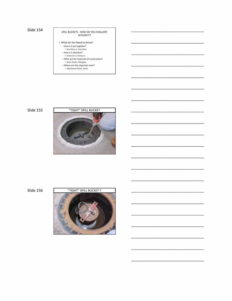
Slide 154 SPILL BUCKETS - HOW DO YOU EVALUATE
INTEGRITY?
• What do You Need to Know?
– How is it put together?
• One Piece vs. Two Piece
– How is it attached?
• Screw on vs. Clamp on
– What are the materials of construction?
• Steel, Plastic, Fiberglass
– Where are the important seals?
• Attachment Points, Joints
___________________________________
___________________________________
___________________________________
___________________________________
___________________________________
___________________________________
___________________________________
Slide 155 “TIGHT” SPILL BUCKET
___________________________________
___________________________________
___________________________________
___________________________________
___________________________________
___________________________________
___________________________________
Slide 156 “TIGHT” SPILL BUCKET ?
___________________________________
___________________________________
___________________________________
___________________________________
___________________________________
___________________________________
___________________________________

Slide 157 “TIGHT” SPILL BUCKET ?
___________________________________
___________________________________
___________________________________
___________________________________
___________________________________
___________________________________
___________________________________
Slide 158 ONE PIECE CONSTRUCTION
___________________________________
___________________________________
___________________________________
___________________________________
___________________________________
___________________________________
___________________________________
Slide 159 TWO PIECE CONSTRUCTION
___________________________________
___________________________________
___________________________________
___________________________________
___________________________________
___________________________________
___________________________________

Slide 160 SCREW ON INSTALLATION
___________________________________
___________________________________
___________________________________
___________________________________
___________________________________
___________________________________
___________________________________
Slide 161 SLIP ON INSTALLATION
___________________________________
___________________________________
___________________________________
___________________________________
___________________________________
___________________________________
___________________________________
Slide 162 SLIP ON INSTALLATION
COMPRESSION SEAL
___________________________________
___________________________________
___________________________________
___________________________________
___________________________________
___________________________________
___________________________________

Slide 163 SLIP ON INSTALLATION
COMPRESSION SEAL
BAND CLAMP RUBBER BOOT
___________________________________
___________________________________
___________________________________
___________________________________
___________________________________
___________________________________
___________________________________
Slide 164
BAND CLAMPS RUBBER BOOT
SLIP ON INSTALLATION
___________________________________
___________________________________
___________________________________
___________________________________
___________________________________
___________________________________
___________________________________
Slide 165
BAND CLAMP
SLIP ON INSTALLATION
___________________________________
___________________________________
___________________________________
___________________________________
___________________________________
___________________________________
___________________________________

Slide 166 TWO PIECE CONSTRUCTION
BASE OR CUP
“BELLOWS”
GRAVEL GUARD
INSIDE BAND CLAMPS
___________________________________
___________________________________
___________________________________
___________________________________
___________________________________
___________________________________
___________________________________
Slide 167
OUTSIDE BAND CLAMPS
TWO PIECE CONSTRUCTION
___________________________________
___________________________________
___________________________________
___________________________________
___________________________________
___________________________________
___________________________________
Slide 168 TWO PIECE CONSTRUCTION
COMPRESSION SEAL
___________________________________
___________________________________
___________________________________
___________________________________
___________________________________
___________________________________
___________________________________

Slide 169 TWO PIECE CONSTRUCTION
ELASTOMERIC SEAL
___________________________________
___________________________________
___________________________________
___________________________________
___________________________________
___________________________________
___________________________________
Slide 170 GOT BALL FLOAT VALVES ?
___________________________________
___________________________________
___________________________________
___________________________________
___________________________________
___________________________________
___________________________________
Slide 171 TIGHT ?
WATER TABLE BELOW BASE
WATER TABLE ABOVE BASE
___________________________________
___________________________________
___________________________________
___________________________________
___________________________________
___________________________________
___________________________________

Slide 172 Chapter 7: Secondary Containment & Spill/Overfill Prevention
Secondary Containment
– Double-walled tanks
– Double-walled piping
– Containment sumps (single or double-walled)• Dispenser sumps (under dispenser containment)• Tank sumps
___________________________________
___________________________________
___________________________________
___________________________________
___________________________________
___________________________________
___________________________________
Slide 173 Chapter 7: Secondary Containment & Spill/Overfill Prevention
Secondary Containment
Double-walled tanks• Steel• FRP• Composite
Interstice may be wet or dry• Steel/Composite tanks = dry• FRP tanks = wet or dry
___________________________________
___________________________________
___________________________________
___________________________________
___________________________________
___________________________________
___________________________________
Slide 174 Chapter 7: Secondary Containment & Spill/Overfill Prevention
Secondary Containment
Double-walled piping• FRP• Thermoplastic• Composite• Steel?
– 3 over 2 type (FRP)– Coaxial type– Variations
– Interstice may be wet or dry
___________________________________
___________________________________
___________________________________
___________________________________
___________________________________
___________________________________
___________________________________
Slide 175 Chapter 7: Secondary Containment & Spill/Overfill Prevention
Secondary Containment
Containment Sumps• FRP• Thermoplastic• Steel
– Sumps themselves may be double-walled
– Dispenser Pans or Sumps
– One piece or two piece
– Source of problems:• Penetration fittings• Lid• Sump itself
___________________________________
___________________________________
___________________________________
___________________________________
___________________________________
___________________________________
___________________________________
Slide 176 Chapter 7: Secondary Containment & Spill/Overfill Prevention
Secondary Containment
Monitoring/Observation Wells
Do I still need to install an observation well in the tank bed if everything must be double-walled with interstitial monitoring anyway?
___________________________________
___________________________________
___________________________________
___________________________________
___________________________________
___________________________________
___________________________________
Slide 177 Chapter 7: Secondary Containment & Spill/Overfill Prevention
Secondary Containment
Installation Testing
Any tank, pipe, sump or spill bucket should be tested after installation and carefully documented to ensure integrity (and protect the installer).
___________________________________
___________________________________
___________________________________
___________________________________
___________________________________
___________________________________
___________________________________

Slide 178 Chapter 8: Piping: Layout, Techniques & Materials
Piping in UST Systems
• Product lines• Tank vent lines• Tank fills / risers• Vapor recovery lines• Siphon bars• Valves • Fittings• Dispensers
___________________________________
___________________________________
___________________________________
___________________________________
___________________________________
___________________________________
___________________________________
Slide 179 Chapter 8: Piping: Layout, Techniques & Materials
Where the leaks are
API study estimated 1/3 of all leaks occurred in piping
Original EPA estimates were much higher
Why did so many piping leaks occur before the regulations came about?
Why do so many piping leaks occur these days?
___________________________________
___________________________________
___________________________________
___________________________________
___________________________________
___________________________________
___________________________________
Slide 180 Chapter 8: Piping: Layout, Techniques & Materials
Piping Slope
– Used to be that piping slope recommendations were ½ inch per foot.
– Changed to 1/8 inch per foot
– Slope requirements for pressurized lines have been done away with in most recent edition of PEI RP100
– Why is slope no longer required?
___________________________________
___________________________________
___________________________________
___________________________________
___________________________________
___________________________________
___________________________________

Slide 181 Chapter 8: Piping: Layout, Techniques & Materials
Piping Layout
General rules of thumb
– Do not run pipe across tanks – Have pipe come off ends of tanks
– Keep distance between tanks and dispensers as short as possible
– Route piping parallel to dispensers
___________________________________
___________________________________
___________________________________
___________________________________
___________________________________
___________________________________
___________________________________
Slide 182 Chapter 8: Piping: Layout, Techniques & Materials
Depth of Piping Burial
– PEI says 18 inches (including paving)
– API says 12 inches
– Manufacturers may be different
– Depends on size of pipe also(2 inch vs. 3 inch)
___________________________________
___________________________________
___________________________________
___________________________________
___________________________________
___________________________________
___________________________________
Slide 183 Chapter 8: Piping: Layout, Techniques & Materials
Piping Separation Distances
– PEI says pipe must be separated by at least twice the pipe diameter (for 2 inch pipe separation distance must be 4 inches)
– PEI says pipe must be at least 6 inches from floor (provide 6 inches of bedding)
– PEI says pipe must be separated from the sidewalls of the trench by at least 6 inches
– Manufacturers may be different
___________________________________
___________________________________
___________________________________
___________________________________
___________________________________
___________________________________
___________________________________
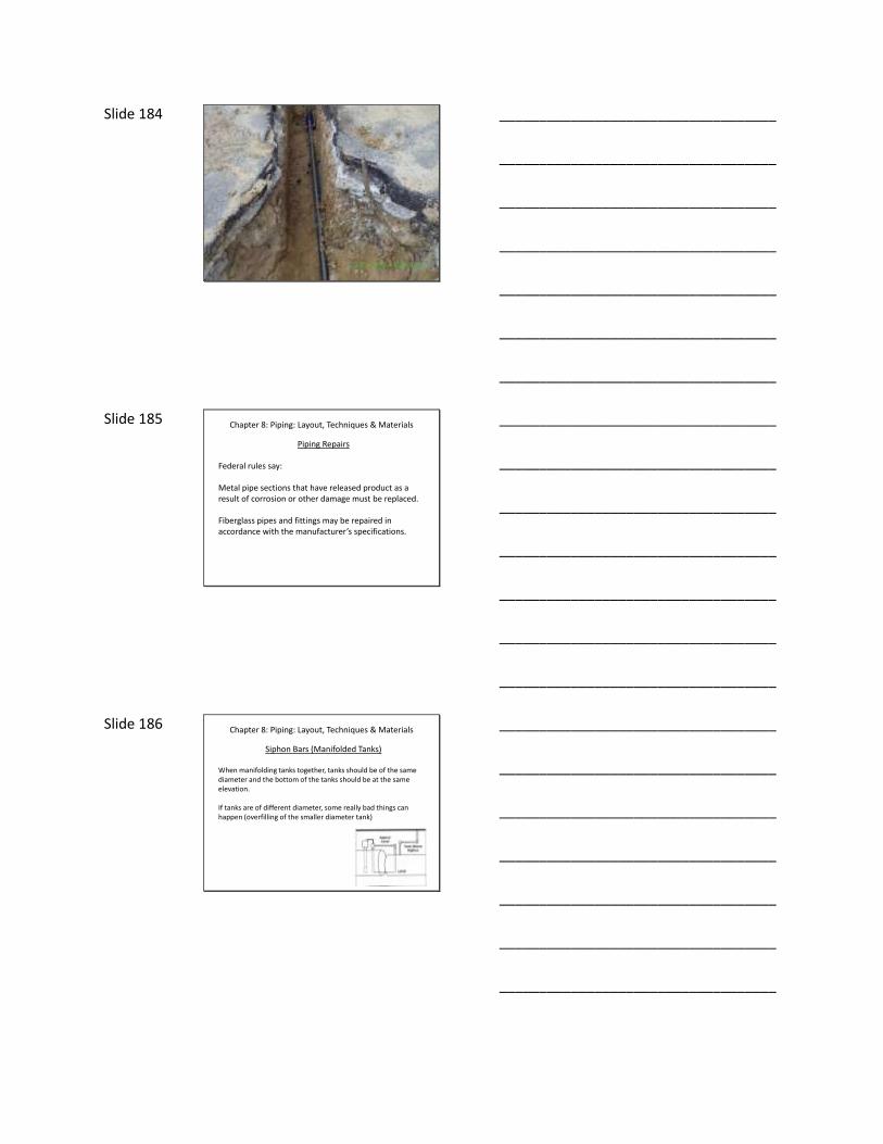
Slide 184
___________________________________
___________________________________
___________________________________
___________________________________
___________________________________
___________________________________
___________________________________
Slide 185 Chapter 8: Piping: Layout, Techniques & Materials
Piping Repairs
Federal rules say:
Metal pipe sections that have released product as a result of corrosion or other damage must be replaced.
Fiberglass pipes and fittings may be repaired in accordance with the manufacturer’s specifications.
___________________________________
___________________________________
___________________________________
___________________________________
___________________________________
___________________________________
___________________________________
Slide 186 Chapter 8: Piping: Layout, Techniques & Materials
Siphon Bars (Manifolded Tanks)
When manifolding tanks together, tanks should be of the same diameter and the bottom of the tanks should be at the same elevation.
If tanks are of different diameter, some really bad things can happen (overfilling of the smaller diameter tank)
___________________________________
___________________________________
___________________________________
___________________________________
___________________________________
___________________________________
___________________________________

Slide 187 Chapter 8: Piping: Layout, Techniques & Materials
Vent Lines
Size is important
API 1615– 2 inch vents adequate for 4 inch drop hoses– Bury at least 12 inches– Slope uniformly toward tanks @ 1/8 inch/foot– Sags and traps should be avoided
NFPA 30 has calculations for vent sizes
___________________________________
___________________________________
___________________________________
___________________________________
___________________________________
___________________________________
___________________________________
Slide 188 Chapter 8: Piping: Layout, Techniques & Materials
Vent Lines
Vent Discharge – Class 1 Liquids
Freestanding vents must be at least 12 feet high and have adequate support
Vents installed adjacent to buildings must be 2 feet above the adjacent roof line and no less than 5 feet from any openings
Must use Schedule 40 steel pipingfor above ground vent lines
___________________________________
___________________________________
___________________________________
___________________________________
___________________________________
___________________________________
___________________________________
Slide 189 Chapter 8: Piping: Layout, Techniques & Materials
Vent Lines
Manifolding
Size must be adequate to vent all tanks if they are simultaneously filled
Should not manifold vents of tanks containing different classes of liquids (diesel vs. gasoline)
___________________________________
___________________________________
___________________________________
___________________________________
___________________________________
___________________________________
___________________________________

Slide 190 Chapter 8: Piping: Layout, Techniques & Materials
Piping Material Selection
Under the proposed change to the federal rules, all new piping must be secondarily contained.
– Fiberglass Reinforced Plastic• Smith• Ameron
– Thermoplastic• APT/UPP• OPW• NUPI• IPP
– Steel• Double-walled?
– Composite• Brugg• DoubleTrac
___________________________________
___________________________________
___________________________________
___________________________________
___________________________________
___________________________________
___________________________________
Slide 191 Chapter 8: Piping: Layout, Techniques & Materials
Methods of Providing Flexibility
– Flex connectors
– Swing Joints
– Flexible Piping
Must provide flexibility where piping is connected to tanks and dispensers.
___________________________________
___________________________________
___________________________________
___________________________________
___________________________________
___________________________________
___________________________________
Slide 192 Chapter 8: Piping: Layout, Techniques & Materials
Flex Connector Corrosion Protection
– Existing flex connectors must be protected from corrosion by:
• Isolation from contact with the soil/water– Dry sumps– Boots– Removal of all soil
• Cathodic protection
___________________________________
___________________________________
___________________________________
___________________________________
___________________________________
___________________________________
___________________________________

Slide 193 Chapter 8: Piping: Layout, Techniques & Materials
Types of Flex Connectors
– Stainless Steel• End fittings not stainless
– Non-Metallic• End fittings not non-metallic
– Soil Safe• End fittings not soil safe
– Double-walled?
___________________________________
___________________________________
___________________________________
___________________________________
___________________________________
___________________________________
___________________________________
Slide 194 Chapter 8: Piping: Layout, Techniques & Materials
Types of Flex Connectors
– Fire Rated• Generally required if used in sumps
– Not Fire Rated• Generally O.K. if direct buried
___________________________________
___________________________________
___________________________________
___________________________________
___________________________________
___________________________________
___________________________________
Slide 195 Chapter 8: Piping: Layout, Techniques & Materials
Fiberglass Reinforced Piping
General Rules of Thumb
• Joints must be cleaned (acetone) before gluing• Tapered ends must be protected from UV rays• Curing temperatures are critical (600 F minimum)
– Heat packs may be necessary
• Threaded connections made with compatible dope• Spigot type joints must be fully inserted into bell• Male FRP threads joined to female steel threads• “Clamshells” must be thoroughly sanded/cleaned
– “LCX” joints must be thoroughly sanded– Usually takes more glue than you think
___________________________________
___________________________________
___________________________________
___________________________________
___________________________________
___________________________________
___________________________________
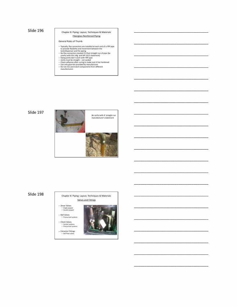
Slide 196 Chapter 8: Piping: Layout, Techniques & Materials
Fiberglass Reinforced Piping
General Rules of Thumb
– Typically, flex connectors are installed at each end of a FRP pipe to provide flexibility and movement between the tank/dispenser and the piping
– No flex connectors needed if 4 foot straight run of pipe (be careful with this mfg. and API 1615 statement)
– Swing joints don’t work with FRP pipe– Joints must be straight – not cocked– Check adhesive after curing to make sure it has hardened– Use only glue kits provided by manufacturer– Do not mix and match components from different
manufacturers
___________________________________
___________________________________
___________________________________
___________________________________
___________________________________
___________________________________
___________________________________
Slide 197 Be carful with 4’ straight run manufacturer’s statement
___________________________________
___________________________________
___________________________________
___________________________________
___________________________________
___________________________________
___________________________________
Slide 198 Chapter 8: Piping: Layout, Techniques & Materials
Valves and Fittings
– Shear Valves• Single poppet• Double poppet
– Ball Valves• Pressurized systems
– Check Valves• Suction systems• Pressurized systems
– Extractor Fittings• Ball float valves
___________________________________
___________________________________
___________________________________
___________________________________
___________________________________
___________________________________
___________________________________

Slide 199 Chapter 8: Piping: Layout, Techniques & Materials
Valves and Fittings
– Shear Valves (aka Crash, Impact, Emergency Valves)
• Installed underneath dispensers on all pressurized piping
• Must be installed so that shear section is within 1/2 inch of grade level
• Must be securely anchored
• Fire codes generally require that shear valves be tested annually
• Thermal mechanism (fusible link) must be operative
– Are shear valves required on satellite dispensers?
– “Nuisance” breaks
___________________________________
___________________________________
___________________________________
___________________________________
___________________________________
___________________________________
___________________________________
Slide 200 Chapter 8: Piping: Layout, Techniques & Materials
Valves and Fittings
– Ball Valves
• Installed in Pressure Systems (can/should be installed in suction systems?)
– Isolate piping for testing purposes» Precision line testing
– Isolate certain sections of piping for repairs» Dual feed piping systems
___________________________________
___________________________________
___________________________________
___________________________________
___________________________________
___________________________________
___________________________________
Slide 201 Chapter 8: Piping: Layout, Techniques & Materials
Valves and Fittings
– Check Valves
• Suction Systems– Foot valves– Angle check valves– Union check valves
• Pressure Systems– In-line check valves (dual STPs)– Pressure relief (functional element)
___________________________________
___________________________________
___________________________________
___________________________________
___________________________________
___________________________________
___________________________________

Slide 202 Chapter 8: Piping: Layout, Techniques & Materials
Valves and Fittings
– Extractor Fittings
• Installed to facilitate removal/inspection of ball float valves
___________________________________
___________________________________
___________________________________
___________________________________
___________________________________
___________________________________
___________________________________
Slide 203 Chapter 8: Piping: Layout, Techniques & Materials
Tank Openings
– Generally 4 inch
– 5 inch (P3 tanks) with nylon bushings
– Double-tap bushings commonly utilized
– Tank fill risers/gauge openings must have striker plates
– Tank fills must have drop tubes (10,000 gallons/month volume)
• Drop tube should allow for at least 4 and less than 6 inches of clearance from the tank bottom to the highest point of the tube cut
– Tank fills must have tight-fill adapters• Top seal• Side seal
4-6”
___________________________________
___________________________________
___________________________________
___________________________________
___________________________________
___________________________________
___________________________________
Slide 204 Chapter 8: Piping: Layout, Techniques & Materials
Vapor Recovery
– Stage 1 / Stage 2
– Stage 1 required if volume is 100,000 gallons or greater per month
– Stage 2 required in certain ozone non-attainment areas
• Stage 2 being phased out –on board vehicle vapor recovery (wide-spread use designation)
___________________________________
___________________________________
___________________________________
___________________________________
___________________________________
___________________________________
___________________________________

Slide 205 Chapter 8: Piping: Layout, Techniques & Materials
Vapor Recovery
Stage 1
When a delivery to a tank is being made, the truck connects two hoses per product.
– 4 inch hose to drop fuel into the tank
– 3 inch hose to return vapors to the truck
– Pressure/Vacuum caps required on vents
– Tight fill adapters are generally swivel type
___________________________________
___________________________________
___________________________________
___________________________________
___________________________________
___________________________________
___________________________________
Slide 206 Chapter 8: Piping: Layout, Techniques & Materials
Vapor Recovery
Stage 1
Two ways to accomplish:
1. Two point (poppet installed in tank vent riser)2. Coaxial (special drop tube & tight fill adapter)
Tank vapor recovery may be manifolded
“Issues” with deliveries reported
___________________________________
___________________________________
___________________________________
___________________________________
___________________________________
___________________________________
___________________________________
Slide 207
Stick Reading 50.5 inches = 5600 gallons ullage
Actual Fuel Level Approx 68 inches = 3000 gallons ullage
“NEW” NESHAP STAGE 1 VAPOR RECOVERY RULES
12,000 gallon 8’ diameter tank
___________________________________
___________________________________
___________________________________
___________________________________
___________________________________
___________________________________
___________________________________

Slide 208 Chapter 8: Piping: Layout, Techniques & Materials
Vapor Recovery
Stage 2
Vapors are collected at dispenser nozzles as automobiles are filled and returned to tanks:
Two ways to accomplish:1. Vacuum assist2. Balance
Requires coaxial dispenser hoses
Must have dedicated piping from dispensers back to tanks
___________________________________
___________________________________
___________________________________
___________________________________
___________________________________
___________________________________
___________________________________
Slide 209 Chapter 8: Piping: Layout, Techniques & Materials
Identification of Manholes & Fill pipes
API 1637
White = Regular gasolineBlue = Midgrade gasolineRed = Premium gasolineYellow = Diesel
___________________________________
___________________________________
___________________________________
___________________________________
___________________________________
___________________________________
___________________________________
Slide 210 Chapter 8: Piping: Layout, Techniques & Materials
Identification of Manholes & Fill pipes
Monitoring wells must be clearly marked (usually a black triangle) to prevent any mistakes
___________________________________
___________________________________
___________________________________
___________________________________
___________________________________
___________________________________
___________________________________

Slide 211 Chapter 9: Installation of Tank Related Equipment
FIRE CODES
NFPA 30
NFPA 30A
Uniform Fire Code Chapter 59International Fire Code Institute
Many of the requirements NFPA 30A reference Chapter 59
Must determine what fire code your state/county/city has adopted
___________________________________
___________________________________
___________________________________
___________________________________
___________________________________
___________________________________
___________________________________
Slide 212 Chapter 9: Installation of Tank Related Equipment
FIRE CODES
Dispensers
• Must be installed 10 feet from property lines
• 5 feet from building openings
• 20 feet from any ignition source– UFC requires 20 feet from extended nozzle
• Must be mounted on a concrete island or otherwise protected from collision
– Island must be 6 inches high– Bollards
• Must be bolted in place
___________________________________
___________________________________
___________________________________
___________________________________
___________________________________
___________________________________
___________________________________
Slide 213 Chapter 9: Installation of Tank Related Equipment
FIRE CODES
Dispenser Hoses
• Hose may not be more than 18 feet long
• Marina hose may be longer but must have hose reel
• Hose must be electrically conductive to dissipate static charges
___________________________________
___________________________________
___________________________________
___________________________________
___________________________________
___________________________________
___________________________________

Slide 214 Chapter 9: Installation of Tank Related Equipment
FIRE CODES
Dispenser Nozzle Hold Open Latches
• NFPA says may or may not have hold open latches
• UFC says self serve must have hold open latches
• Some local fire officials ban hold open latches
• Classic Catch-22– If you don’t allow, customers will devise a way to hold open– If you allow, must trust customer
___________________________________
___________________________________
___________________________________
___________________________________
___________________________________
___________________________________
___________________________________
Slide 215 Chapter 9: Installation of Tank Related Equipment
FIRE CODES
Dispenser Hose Breakaways
• Required by fire codes
• “Dated expiration”
• If hose is connected to a retriever mechanism, breakaway must be located between nozzle and the point where the retriever is located
___________________________________
___________________________________
___________________________________
___________________________________
___________________________________
___________________________________
___________________________________
Slide 216 Chapter 9: Installation of Tank Related Equipment
FIRE CODES
Non-Gasoline Dispensers
• Kerosene dispensers and certain others must be located at least 20 feet from Class I (gasoline) dispensers
• Nozzle is usually a different size
• Intent is to minimize the potential for mistakes
___________________________________
___________________________________
___________________________________
___________________________________
___________________________________
___________________________________
___________________________________
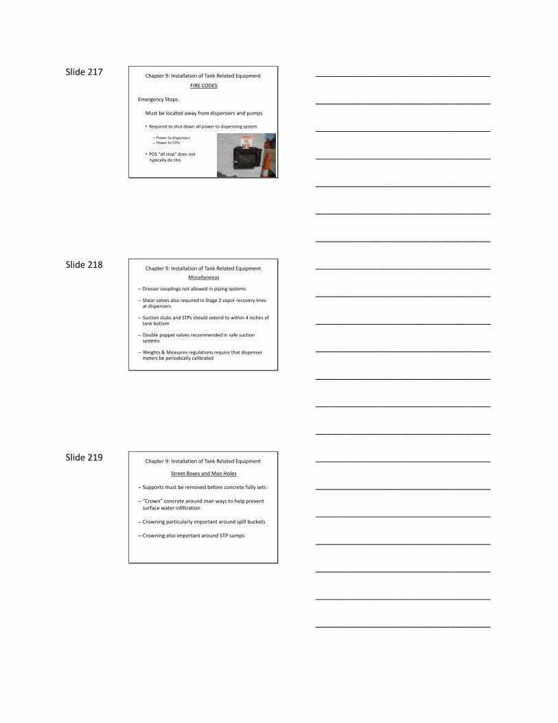
Slide 217 Chapter 9: Installation of Tank Related Equipment
FIRE CODES
Emergency Stops
Must be located away from dispensers and pumps
• Required to shut down all power to dispensing system
– Power to dispensers– Power to STPs
• POS “all stop” does not typically do this
___________________________________
___________________________________
___________________________________
___________________________________
___________________________________
___________________________________
___________________________________
Slide 218 Chapter 9: Installation of Tank Related Equipment
Miscellaneous
– Dresser couplings not allowed in piping systems
– Shear valves also required in Stage 2 vapor recovery lines at dispensers
– Suction stubs and STPs should extend to within 4 inches of tank bottom
– Double poppet valves recommended in safe suction systems
– Weights & Measures regulations require that dispenser meters be periodically calibrated
___________________________________
___________________________________
___________________________________
___________________________________
___________________________________
___________________________________
___________________________________
Slide 219 Chapter 9: Installation of Tank Related Equipment
Street Boxes and Man Holes
– Supports must be removed before concrete fully sets
– “Crown” concrete around man ways to help prevent surface water infiltration
– Crowning particularly important around spill buckets
– Crowning also important around STP sumps
___________________________________
___________________________________
___________________________________
___________________________________
___________________________________
___________________________________
___________________________________

Slide 220 Chapter 9: Installation of Tank Related Equipment
Documentation and Training
– Carefully document every aspect of installation – pictures are very important and should be taken at every opportunity during the installation
– Once installation is complete, make sure the owner/operator is trained on the interfaces with the system and routine maintenance and operation requirements
• ATG system• POS system• Testing requirements• Maintenance requirements• Recognition and significance of various alarms, warnings, symptoms
– Insure the contractor provides copies of manufacturers’ literature• Performance claims• Operating instructions• Maintenance requirements
– Good idea to make sure regulators, fire officials understand system and how it works
___________________________________
___________________________________
___________________________________
___________________________________
___________________________________
___________________________________
___________________________________
Slide 221 Chapter 10: Tank System Electrical Installation
NFPA - National Electrical Code
– Typically, the tank installer subcontracts the electrical installation to a licensed electrician
– Also typically, the tank installer is ultimately responsible for the electricians work
– Possible that contract stipulates the electrical is separate but tank installer should still have basic understanding of what is required
___________________________________
___________________________________
___________________________________
___________________________________
___________________________________
___________________________________
___________________________________
Slide 222 Chapter 10: Tank System Electrical Installation
NFPA – National Electrical Code
– Classification
• Of substance (propensity to produce flammable vapors)
– Flash Point is utilized for liquids to determine propensity to produce flammable vapors
“The minimum temperature at which a liquid gives off a vapor in sufficient concentration to form an ignitable mixture with air near the surface of the liquid.”
• Of location (must determine likelihood of vapor exposure)
___________________________________
___________________________________
___________________________________
___________________________________
___________________________________
___________________________________
___________________________________

Slide 223 Chapter 10: Tank System Electrical Installation
NFPA – National Electrical Code
– Classification of Flammable & Combustible Liquids
• Class I - Flash Point < 100°F (Class 1A & 1B < 73°F)– Gasoline
• Class II - Flash Point ≥ 100°F, but < 140°F – Diesel
• Class IIIA - Flash Point ≥ 140°F– Heating Oil
___________________________________
___________________________________
___________________________________
___________________________________
___________________________________
___________________________________
___________________________________
Slide 224 Chapter 10: Tank System Electrical Installation
NFPA – National Electrical Code
– Classification of Location
• Locations are classified into two Divisions
– Division 1– Division 2
– Divisions are determined based on the frequency by which certain conditions can be expected to occur at the location
___________________________________
___________________________________
___________________________________
___________________________________
___________________________________
___________________________________
___________________________________
Slide 225 Chapter 10: Tank System Electrical Installation
NFPA – National Electrical Code
– Division 1 Location
• The hazard of ignitable concentrations of gases or vapors can exist under normal operating conditions
• Ignitable concentrations of vapors may occur frequently because of repair or maintenance operations or because leaks are likely to occur at that location
• breakdown or faulty operation of equipment might release ignitable concentrations of flammable vapors, and might also cause simultaneous failure of electric equipment
___________________________________
___________________________________
___________________________________
___________________________________
___________________________________
___________________________________
___________________________________

Slide 226 Chapter 10: Tank System Electrical Installation
NFPA – National Electrical Code
– Division 2
• Flammable gases are handled but normally confined inside a closed system—can escape only in case of accidental rupture
• A mechanical ventilation system removes hazardous concentrations of vapors
• Ignitable concentrations of vapors might occasionally stray (location is next to or near a Division 1 location)
___________________________________
___________________________________
___________________________________
___________________________________
___________________________________
___________________________________
___________________________________
Slide 227 Chapter 10: Tank System Electrical Installation
NFPA – National Electrical Code
– Consider Gasoline Tank Vent Discharge
• Substance is Class I
• Area within 3 feet of vent discharge is Division 1
• Area from 3 feet to 5 feet of vent discharge is Division 2
___________________________________
___________________________________
___________________________________
___________________________________
___________________________________
___________________________________
___________________________________
Slide 228 Chapter 10: Tank System Electrical Installation
NFPA – National Electrical Code
– Flammable vs. Combustible Liquids
• Combustible = Flash point above 100o F– Diesel, Kerosene, Heating Oil
• Flammable = Flash point below 100o F– Gasoline, Ethanol
Flash point—the minimum temperature at which the liquid gives off vapors in sufficient concentration to form an ignitable mixture
___________________________________
___________________________________
___________________________________
___________________________________
___________________________________
___________________________________
___________________________________

Slide 229 Chapter 10: Tank System Electrical Installation
Fuel Flash pointAuto ignitiontemperature
Ethanol 55 °F 685
Gasoline -45 °F 475
Diesel 140 410
Jet fuel 140 410
Kerosene 100–162 °F 428
Vegetable oil (canola) 621
Biodiesel 266
___________________________________
___________________________________
___________________________________
___________________________________
___________________________________
___________________________________
___________________________________
Slide 230 Chapter 10: Tank System Electrical Installation
NFPA – National Electrical Code
– Electrical Area Classifications
• NFPA 30A applies to Marina and Service Stations only
– NFPA 30A - Table 7 is a good reference for determining Division 1 vs. Division 2 classification of gas station areas
• NFPA 30 should be referenced for other facilities– Bulk Plants– Loading Racks
___________________________________
___________________________________
___________________________________
___________________________________
___________________________________
___________________________________
___________________________________
Slide 231 Chapter 10: Tank System Electrical Installation
NFPA – National Electrical Code
– Electrical Area Classifications
• Division 1 = The potential for the presence of ignitable vapors is more or less constant
• Division 2 = The potential for hazard exists only infrequently or under abnormal conditions
___________________________________
___________________________________
___________________________________
___________________________________
___________________________________
___________________________________
___________________________________

Slide 232 Chapter 10: Tank System Electrical Installation
NFPA – National Electrical Code
• Consider the Electrical Area Classification for Gasoline
• Division 1
– Tanks = Sump, pit, man way or below grade opening over a tank (vapors heavier than air)
– Dispensers = Area within a dispenser enclosure (dispenser sump, cabinet)
• Division 2
– Tanks = Area above grade level of tank openings (extends 18 inches above grade and within a 5 foot radius).
– Dispensers = Area adjacent to dispensers (extends 18 inches above grade and within a 20 foot radius).
___________________________________
___________________________________
___________________________________
___________________________________
___________________________________
___________________________________
___________________________________
Slide 233 Chapter 10: Tank System Electrical Installation
NFPA – National Electrical Code
– Intrinsically Safe
• Electrical components that operate at very low voltage level, as well as at a low level of amperage, capacitance, and inductance.
• Voltage is too low to have enough energy to cause ignition
___________________________________
___________________________________
___________________________________
___________________________________
___________________________________
___________________________________
___________________________________
Slide 234 Chapter 10: Tank System Electrical Installation
NFPA – National Electrical Code
– Explosion Proof
• Case prevents any spark from escaping to the outside and igniting vapors
• Case can withstand internal explosion
• Case does not get hot enough to ignite external vapors
___________________________________
___________________________________
___________________________________
___________________________________
___________________________________
___________________________________
___________________________________

Slide 235 Chapter 10: Tank System Electrical Installation
NFPA – National Electrical Code
– Explosion Proof Fittings
– “Seal offs” in conduits are common example• Under dispensers• At STPs
– Conduits in Class I-Division 1 areas must be rigid metal
– Rigid non-metallic conduit may be used for underground wiring if it is buried at least 24 inches deep, and if metallic conduit is used for the last two feet before the wiring emerges or connects with an above-ground raceway.
___________________________________
___________________________________
___________________________________
___________________________________
___________________________________
___________________________________
___________________________________
Slide 236 Chapter 10: Tank System Electrical Installation
NFPA – National Electrical Code
Circuit Disconnects
Each circuit leading to or through a dispensing pump shall be provided with a switch or other acceptable means to disconnect simultaneously from the source of supply all conductors of the circuit, including the grounded neutral, if any.
___________________________________
___________________________________
___________________________________
___________________________________
___________________________________
___________________________________
___________________________________
Slide 237 Chapter 10: Tank System Electrical Installation
NFPA – National Electrical Code
– Burial Depth
• Rigid Metallic Conduit– 6 inches in non-traffic areas– 24 inches in traffic areas
• Rigid Non-Metallic Conduit– 18 inches in non-traffic areas– 24 inches in traffic areas
– Wiring conduits should be separated from product piping by at least 6 inches
• When possible, route electrical conduits away from product piping
– Wiring for intrinsically safe circuits may not be in same conduit as higher voltage circuits
___________________________________
___________________________________
___________________________________
___________________________________
___________________________________
___________________________________
___________________________________

Slide 238 Chapter 11: Tank System Release Detection
LEAK vs. RELEASE
– Leak is any breech in the primary containment
– Release is any leak that reaches the environment
– “In-tank” vs. External leak detection methods
– Regardless, leak detection must be conducted at least monthly (every 30 days)
___________________________________
___________________________________
___________________________________
___________________________________
___________________________________
___________________________________
___________________________________
Slide 239 Chapter 11: Tank System Release Detection
– Obviously, our objective is to design, install, operate and maintain UST systems so that leaks do not occur
– However, no matter what we do, leaks will continue to occur
– Therefore, we want to be able to detect leaks as accurately and as soon as possible so that the impact to the environment is zero or as small as possible
___________________________________
___________________________________
___________________________________
___________________________________
___________________________________
___________________________________
___________________________________
Slide 240 Chapter 11: Tank System Release Detection
METHODS OF LEAK DETECTION
Tank Leak Detection vs. Piping Leak Detection
– Some of methods of leak detection apply to both but some do not
– We will speak about tank leak detection first andthen piping leak detection separately
___________________________________
___________________________________
___________________________________
___________________________________
___________________________________
___________________________________
___________________________________

Slide 241 Chapter 11: Tank System Release Detection
METHODS OF TANK LEAK DETECTION
• Inventory Control – Daily tank sticking & reconciliation of sales/deliveries. Conducted in conjunction with periodic PTT
• Statistical Inventory Reconciliation – Monthly computer analysis of inventory data
• Manual Tank Gauging – Weekly sticking of small tanks
• Groundwater/Vapor Monitoring – Monthly observation
• Automatic Tank Gauging – Computerized monitoring of liquid levels
• Interstitial Monitoring – Monitoring of secondary containment• Only option available for new tanks installed under proposed federal rule
change
• Other Methods – Warren Rogers
___________________________________
___________________________________
___________________________________
___________________________________
___________________________________
___________________________________
___________________________________
Slide 242 Chapter 11: Tank System Release Detection
METHODS OF TANK LEAK DETECTION
Inventory Control – Only allowed for 10 years following tank installation or upgrade to meet 1998 federal deadline for corrosion protection, spill protection and overfill protection
• After 10 years – alternative method of leak detection is required
Must be conducted in conjunction withPeriodic precision tightness testing.
___________________________________
___________________________________
___________________________________
___________________________________
___________________________________
___________________________________
___________________________________
Slide 243 Chapter 11: Tank System Release Detection
METHODS OF TANK LEAK DETECTION
Inventory Control• Tank inventory is obtained daily (sticking or ATG)• Sales are obtained daily (dispenser totalizers)• Sales are compared to tank inventory daily• At the end of the month, daily variance is totaled• Total variance is compared with standard• Standard is 130 gallons + 1% throughput
• If total variance for the month is greater than standard –Suspected release must be reported
___________________________________
___________________________________
___________________________________
___________________________________
___________________________________
___________________________________
___________________________________

Slide 244 Chapter 11: Tank System Release Detection
METHODS OF TANK LEAK DETECTION
Statistical Inventory Reconciliation (SIR)
• Tank inventory is obtained daily (stick or ATG)• Sales are obtained daily (dispenser totalizers)• Data is processed with computer program (usually a 3rd party)• Computer program analyzes data to determine if the system
is leaking or not– Pass – No leak– Fail – Leak suspected– Inconclusive – Can’t make the call
• Two consecutive inconclusives or a fail require tightness test(generally accepted approach nationwide)
___________________________________
___________________________________
___________________________________
___________________________________
___________________________________
___________________________________
___________________________________
Slide 245
Behavior of Water in E-10 Tanks
E-10 & Tank Tightness Testing
Because water readily mixes with ethanol,
there is not normally any layer of water on
the bottom of an ethanol blend tank.
In an E-10 tank, the fuel can absorb around
0.5% water before phase separation occurs.
5 gallons water / 1000 gallons fuel
___________________________________
___________________________________
___________________________________
___________________________________
___________________________________
___________________________________
___________________________________
Slide 246
Behavior of Water in E-10 tanks
Once phase separation occurs, the ethanol /
water mix will fall-out and go to the bottom.
There is still not a layer of “free” water on
the bottom of the tank – It is a mix of
ethanol, water and other hydrocarbons.
E-10 & Tank Tightness Testing
___________________________________
___________________________________
___________________________________
___________________________________
___________________________________
___________________________________
___________________________________
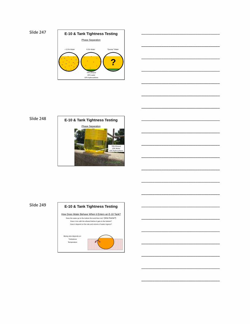
Slide 247
Phase Separation
< 0.5% Water 0.5% Water “Excess” Water
70% ethanol
20% water
10% hydrocarbons
?
E-10 & Tank Tightness Testing
___________________________________
___________________________________
___________________________________
___________________________________
___________________________________
___________________________________
___________________________________
Slide 248
Phase Separation
70% Ethanol20% Water
10% Hydrocarbons
E-10 & Tank Tightness Testing
___________________________________
___________________________________
___________________________________
___________________________________
___________________________________
___________________________________
___________________________________
Slide 249
How Does Water Behave When it Enters an E-10 Tank?
Does the water go to the bottom first and then mix? (time frame?)
Does it mix with the ethanol before it gets to the bottom?
Does it depend on the rate and volume of water ingress?
Mixing also depends on:
Turbulence
Temperature
E-10 & Tank Tightness Testing
___________________________________
___________________________________
___________________________________
___________________________________
___________________________________
___________________________________
___________________________________

Slide 250
How Does Water Behavior Potentially Effect Precision Tank
Tightness Testing?
Whenever groundwater is above the bottom of the tank the ability to detect any water
ingress becomes critical.
E-85 tanks – Water ingress can’t be detected with water sensors located at the bottom
of the tank (maybe if phase separation has occurred).
What about E-10 tanks?
E-10 & Tank Tightness Testing
___________________________________
___________________________________
___________________________________
___________________________________
___________________________________
___________________________________
___________________________________
Slide 251
“Vacuum” Precision Tank Tightness Testing
Common tightness testing method
Microphone is placed in the top of the tank
Vacuum is pulled on the ullage
Operator listens for the acoustic characteristics of a leak
Leak in ullage = hiss
Leak below product level = air bubble
Tank Bed is Dry (no groundwater)
E-10 & Tank Tightness Testing
___________________________________
___________________________________
___________________________________
___________________________________
___________________________________
___________________________________
___________________________________
Slide 252
“Vacuum” Precision Tank Tightness Testing
Water sensor must be placed in tank if groundwater is at any level
above the bottom of the tank
Operator listens for the acoustic characteristics of a leak
AND
Must be able to detect ANY ingress of water
Leak in ullage = drip
Leak below product level = water ingress
Tank is Submerged
Groundwater
E-10 & Tank Tightness Testing
___________________________________
___________________________________
___________________________________
___________________________________
___________________________________
___________________________________
___________________________________

Slide 253
“Vacuum” Precision Tank Tightness Testing
Several different scenarios possible depending on relationship between product level
in tank and the groundwater conditions
Leak in ullage = hiss
Leak below product
level and groundwater
Tank is Partially Submerged by Groundwater
Leak below product level
but above groundwater = air bubble
= water ingressGroundwater
E-10 & Tank Tightness Testing
___________________________________
___________________________________
___________________________________
___________________________________
___________________________________
___________________________________
___________________________________
Slide 254
“Vacuum” Precision Tank Tightness Testing
There are a number of “other” issues regarding the ability of these types of testing
systems to detect water ingress:
Tank is Partially Submerged by Groundwater
Tank tilt
Striker plates
Tank sludge
PTT operator
Groundwater
E-10 & Tank Tightness Testing
___________________________________
___________________________________
___________________________________
___________________________________
___________________________________
___________________________________
___________________________________
Slide 255
“Vacuum” Precision Tank Tightness Testing
BTW - What if the hole in the tank happens to be at the same level free product is
at within the tank backfill?
Leak = ?
Tank Partially Submerged with Free Product on Groundwater
Can PTT method
detect an ingress of
free product?
E-10 & Tank Tightness Testing
___________________________________
___________________________________
___________________________________
___________________________________
___________________________________
___________________________________
___________________________________
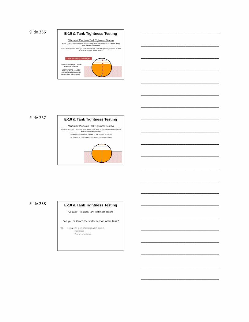
Slide 256
“Vacuum” Precision Tank Tightness Testing
Some types of water sensors (conductivity) must be calibrated in the tank every
time a test is conducted
Calibration involves adding a small amount (50 – 150 ml typically) of water to tank
in order to “trigger” water sensor.
Tank is Partially Submerged
The calibration process is
repeated 3 times
Each time the operator
manually sets the water
sensor just above water.
E-10 & Tank Tightness Testing
___________________________________
___________________________________
___________________________________
___________________________________
___________________________________
___________________________________
___________________________________
Slide 257
“Vacuum” Precision Tank Tightness Testing
To begin calibration, there must already be enough water in the tank (0.014 inches) to be detected by the water sensor.
This water must remain in the tank for the duration of the test.
The duration of the test varies but can be up to nearly an hour.
E-10 & Tank Tightness Testing
___________________________________
___________________________________
___________________________________
___________________________________
___________________________________
___________________________________
___________________________________
Slide 258
“Vacuum” Precision Tank Tightness Testing
Can you calibrate the water sensor in the tank?
YES - Is adding water to an E-10 tank an acceptable practice?
- In any amount
- Under any circumstances
E-10 & Tank Tightness Testing
___________________________________
___________________________________
___________________________________
___________________________________
___________________________________
___________________________________
___________________________________

Slide 259
“Vacuum” Precision Tank Tightness Testing
E-10 QUESTIONS & CONCERNS
Is adding water to the tank an acceptable practice?NO - Is there another way to calibrate water sensor?
BC-250 Diesel Fuel Biocide ?????
BC-250 is the only diesel treatment you'll need because it...-Helps separate water from your fuel. -1 litre of BC-250 per 1,000 litres fuel
Mfg. recommends mixing 1000 ml BC-250 with 5 gallons water for water sensor calibration.
___________________________________
___________________________________
___________________________________
___________________________________
___________________________________
___________________________________
___________________________________
Slide 260
“Vacuum” Precision Tank Tightness Testing
E-10 QUESTIONS & CONCERNS
Can you detect water ingress in an E-10 tank during the tightness test?
To answer this question we must try to answer some other questions first.
The BIG Question
___________________________________
___________________________________
___________________________________
___________________________________
___________________________________
___________________________________
___________________________________
Slide 261
“Vacuum” Precision Tank Tightness Testing
E-10 QUESTIONS & CONCERNS
Does the water go to the bottom of the tank before mixing?
Anecdotally, the answer is YES – The water will go to the bottom of the tank first before it mixes with the ethanol.
However, does it matter what the rate of water ingress is (PTT must be able to detect 0.1 gph)?
___________________________________
___________________________________
___________________________________
___________________________________
___________________________________
___________________________________
___________________________________

Slide 262
12.8 ounces/hour = 1.2 teaspoons/minute = 2.5 drops/second
What exactly is = 0.1 gph ?
0.1 gph = 0.1 ml/second
E-10 & Tank Tightness Testing
___________________________________
___________________________________
___________________________________
___________________________________
___________________________________
___________________________________
___________________________________
Slide 263
“Vacuum” Precision Tank Tightness Testing
How long will the water stay at the bottom of the tank before mixing?
Anecdotally, the water will only stay on the bottom for somewhere around 10-15 minutes before it mixes.
Is 10-15 minutes “residence time” enough?
E-10 & Tank Tightness Testing
___________________________________
___________________________________
___________________________________
___________________________________
___________________________________
___________________________________
___________________________________
Slide 264
“Vacuum” Precision Tank Tightness Testing
E-10 QUESTIONS & CONCERNS
Must be 0.014 inches in the tank initially.
Must add water 3 times to calibrate the water sensor. (0.0095 inches x 3 = 0.0285 inches)
Total water in tank = 0.0425 inches
Because the water sensor position is based on this amount of water at the bottom of the tank, all of this water must remain at the bottom of the tank for the duration of test (up to 1 hour).
Remember our earlier discussion regarding Calibration?
E-10 & Tank Tightness Testing
___________________________________
___________________________________
___________________________________
___________________________________
___________________________________
___________________________________
___________________________________

Slide 265
“Vacuum” Precision Tank Tightness Testing
The calculations done to determine the length of the test assume that all of the water that is already in the tank and all of the water that ingresses during the test will stay at the bottom of the tank for the duration of
the test.
Is 10-15 minutes residence time enough?
E-10 & Tank Tightness Testing
___________________________________
___________________________________
___________________________________
___________________________________
___________________________________
___________________________________
___________________________________
Slide 266
“Vacuum” Precision Tank Tightness Testing
The ephemeral behavior of water at the tank bottom
“melts” these assumptions.
E-10 & Tank Tightness Testing
___________________________________
___________________________________
___________________________________
___________________________________
___________________________________
___________________________________
___________________________________
Slide 267
“Vacuum” Precision Tank Tightness Testing
Are PTT methods that are dependent on a water sensor capable of reliably detecting water ingress in ethanol blend
tanks?
Does it matter what type of water sensor it is?
E-10 & Tank Tightness Testing
___________________________________
___________________________________
___________________________________
___________________________________
___________________________________
___________________________________
___________________________________

Slide 268
“Vacuum” Precision Tank Tightness Testing
Can you detect water ingress in an E-10 tank?
NO
Is there a way to test a single-walled tank with groundwater above the bottom of the tank with “vacuum” PTT methods?
Empty the tank of all fuel ?????
Question
E-10 & Tank Tightness Testing
___________________________________
___________________________________
___________________________________
___________________________________
___________________________________
___________________________________
___________________________________
Slide 269 Chapter 11: Tank System Release Detection
METHODS OF TANK LEAK DETECTION
Manual Tank Gauging • Only applies to those tanks of 2000 gallon capacity or less• Tanks 1001-2000 gallons must also conduct PTT every 5 years• Tank is taken out of service for a period of time each week• Test period depends on size and dimensions of tank• Product level is measured at the beginning of the test period
and again at the end of the test period• Before and after product levels are compared with weekly
standard• Standard depends on the size of the tank• At the end of the month, the four weekly results are averaged
and this is compared with the monthly standard– Pass – No leak– Fail – Leak suspected
___________________________________
___________________________________
___________________________________
___________________________________
___________________________________
___________________________________
___________________________________
Slide 270 Chapter 11: Tank System Release Detection
METHODS OF TANK LEAK DETECTION
Groundwater/Vapor Monitoring• Site assessment needed to determine number, placement,
depth and construction of wells• Groundwater must be within 20 feet of ground surface• Product stored must be immiscible with water• Background conditions must not interfere with monitoring• Every 30 days wells are checked
– Groundwater = visual examination– Vapor = measurement with a vapor meter
• Suspected release =– 1/8 inch or more free product– “High” vapors
___________________________________
___________________________________
___________________________________
___________________________________
___________________________________
___________________________________
___________________________________
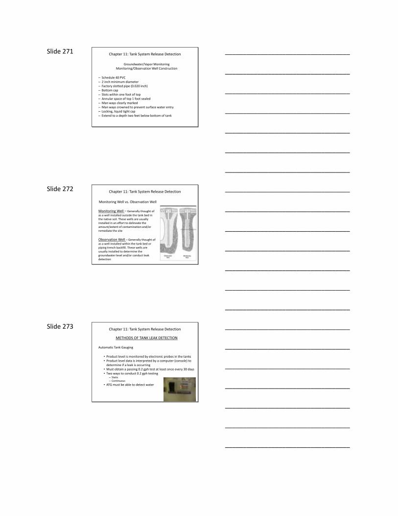
Slide 271 Chapter 11: Tank System Release Detection
Groundwater/Vapor MonitoringMonitoring/Observation Well Construction
– Schedule 40 PVC– 2 inch minimum diameter– Factory slotted pipe (0.020 inch)– Bottom cap– Slots within one foot of top– Annular space of top 1 foot sealed– Man ways clearly marked– Man ways crowned to prevent surface water entry– Locking, liquid tight cap– Extend to a depth two feet below bottom of tank
___________________________________
___________________________________
___________________________________
___________________________________
___________________________________
___________________________________
___________________________________
Slide 272 Chapter 11: Tank System Release Detection
Monitoring Well vs. Observation Well
Monitoring Well – Generally thought of as a well installed outside the tank bed in the native soil. These wells are usually installed in an effort to delineate the amount/extent of contamination and/or remediate the site
Observation Well – Generally thought of as a well installed within the tank bed or piping trench backfill. These wells are usually installed to determine the groundwater level and/or conduct leak detection
___________________________________
___________________________________
___________________________________
___________________________________
___________________________________
___________________________________
___________________________________
Slide 273 Chapter 11: Tank System Release Detection
METHODS OF TANK LEAK DETECTION
Automatic Tank Gauging
• Product level is monitored by electronic probes in the tanks • Product level data is interpreted by a computer (console) to
determine if a leak is occurring • Must obtain a passing 0.2 gph test at least once every 30 days• Two ways to conduct 0.2 gph testing
– Static– Continuous
• ATG must be able to detect water
___________________________________
___________________________________
___________________________________
___________________________________
___________________________________
___________________________________
___________________________________
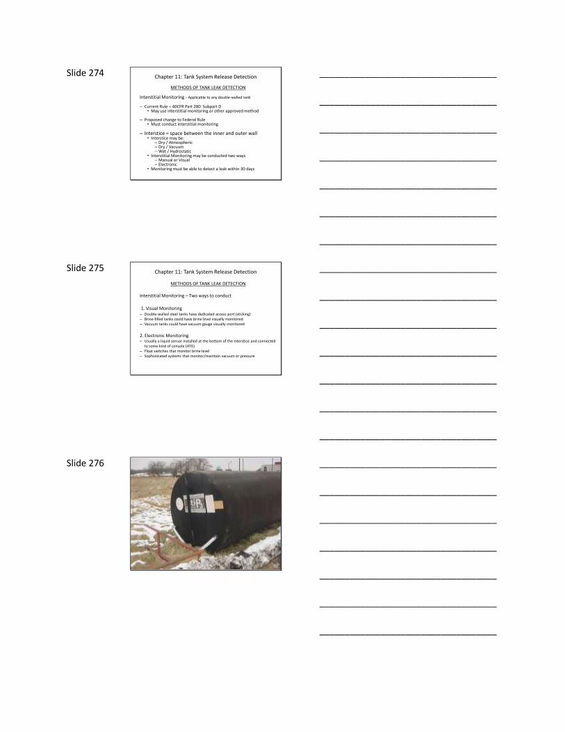
Slide 274 Chapter 11: Tank System Release Detection
METHODS OF TANK LEAK DETECTION
Interstitial Monitoring - Applicable to any double-walled tank
– Current Rule – 40CFR Part 280: Subpart D• May use interstitial monitoring or other approved method
– Proposed change to Federal Rule• Must conduct interstitial monitoring
– Interstice = space between the inner and outer wall • Interstice may be:
– Dry / Atmospheric– Dry / Vacuum– Wet / Hydrostatic
• Interstitial Monitoring may be conducted two ways– Manual or Visual– Electronic
• Monitoring must be able to detect a leak within 30 days
___________________________________
___________________________________
___________________________________
___________________________________
___________________________________
___________________________________
___________________________________
Slide 275 Chapter 11: Tank System Release Detection
METHODS OF TANK LEAK DETECTION
Interstitial Monitoring – Two ways to conduct
1. Visual Monitoring– Double-walled steel tanks have dedicated access port (sticking)– Brine-filled tanks could have brine level visually monitored– Vacuum tanks could have vacuum gauge visually monitored
2. Electronic Monitoring– Usually a liquid sensor installed at the bottom of the interstice and connected
to some kind of console (ATG)– Float switches that monitor brine level– Sophisticated systems that monitor/maintain vacuum or pressure
___________________________________
___________________________________
___________________________________
___________________________________
___________________________________
___________________________________
___________________________________
Slide 276
___________________________________
___________________________________
___________________________________
___________________________________
___________________________________
___________________________________
___________________________________
Slide 277 Chapter 11: Tank System Release Detection
PIPING LEAK DETECTION
• Suction Systems• Check valve at the tank – Leak detection is required• Only check valve is at dispenser – No leak detection required
if other conditions are met (pipe sloped to tank)• Can system be verified?
• Pressurized Systems• Two forms of leak detection required
1. Primary – 0.2 gph monthly standard2. Catastrophic – Automatic line leak detectors (3 gph)
___________________________________
___________________________________
___________________________________
___________________________________
___________________________________
___________________________________
___________________________________
Slide 278 Chapter 11: Tank System Release Detection
PRIMARY METHODS OF PIPING LEAK DETECTION
• Statistical Inventory Reconciliation – Same discussion as for tanks
• Groundwater/Vapor Monitoring – Same discussion as for tanks
• Interstitial Monitoring – Largely the same discussion as for tanks but additional considerations
• Other Methods – Same discussion as for tanks
• Periodic Tightness Testing – Applicable only to piping
___________________________________
___________________________________
___________________________________
___________________________________
___________________________________
___________________________________
___________________________________
Slide 279 Chapter 11: Tank System Release Detection
PRIMARY METHODS OF PIPING LEAK DETECTION
Interstitial Monitoring – Applies to any double-walled piping
– Current Rule
• May use interstitial monitoring or other approved method• Must actually meet the secondary containment requirements if
conducting interstitial monitoring (no water in sumps)
– Proposed change to federal rule
• Must conduct interstitial monitoring
___________________________________
___________________________________
___________________________________
___________________________________
___________________________________
___________________________________
___________________________________
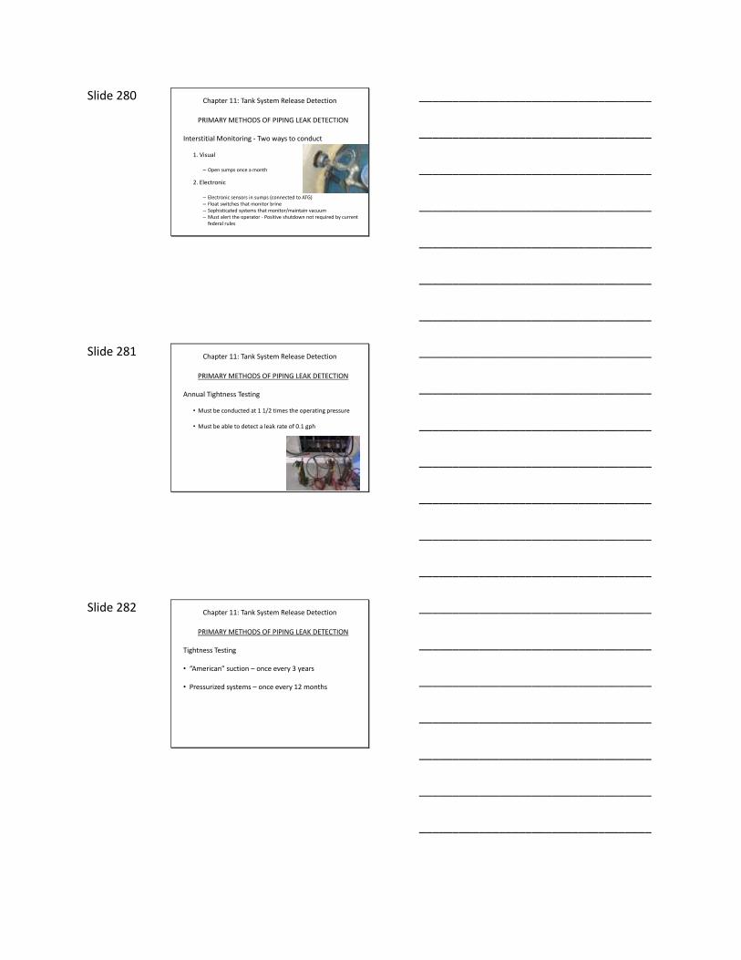
Slide 280 Chapter 11: Tank System Release Detection
PRIMARY METHODS OF PIPING LEAK DETECTION
Interstitial Monitoring - Two ways to conduct
1. Visual
– Open sumps once a month
2. Electronic
– Electronic sensors in sumps (connected to ATG)– Float switches that monitor brine– Sophisticated systems that monitor/maintain vacuum– Must alert the operator - Positive shutdown not required by current
federal rules
___________________________________
___________________________________
___________________________________
___________________________________
___________________________________
___________________________________
___________________________________
Slide 281 Chapter 11: Tank System Release Detection
PRIMARY METHODS OF PIPING LEAK DETECTION
Annual Tightness Testing
• Must be conducted at 1 1/2 times the operating pressure
• Must be able to detect a leak rate of 0.1 gph
___________________________________
___________________________________
___________________________________
___________________________________
___________________________________
___________________________________
___________________________________
Slide 282 Chapter 11: Tank System Release Detection
PRIMARY METHODS OF PIPING LEAK DETECTION
Tightness Testing
• “American” suction – once every 3 years
• Pressurized systems – once every 12 months
___________________________________
___________________________________
___________________________________
___________________________________
___________________________________
___________________________________
___________________________________

Slide 283 Chapter 11: Tank System Release Detection
CATASTROPHIC PRESSURIZED PIPING LEAK DETECTION
Automatic Line Leak Detectors – Required on all pressurized piping (ADEM exception?)
– Must be able to detect a leak equivalent to 3 gph at 10 psi
– Must be tested annually
– Two kinds of devices:1. Mechanical2. Electronic
___________________________________
___________________________________
___________________________________
___________________________________
___________________________________
___________________________________
___________________________________
Slide 284 Chapter 11: Tank System Release Detection
Pressurized Piping Catastrophic Leak Detection
Mechanical Automatic Line Leak Detectors
– Installed in the STP head itself or as close as practical
– Head Pressure can be an issue (38” gasoline = 1 psi)
– Functionality testing is poorly understood
– Suspected leak indicated by slow flow
– Potential issues with high volume/multiple STP sites
___________________________________
___________________________________
___________________________________
___________________________________
___________________________________
___________________________________
___________________________________
Slide 285 Chapter 11: Tank System Release Detection
Pressurized Piping Catastrophic Leak Detection
Electronic Automatic Line Leak Detectors
– Installed in the STP head itself or elsewhere
– Can conduct 3 gph and, if programmed 0.2 gph, 0.1 gph tests
– Head Pressure not a significant issue
– Functionality testing is poorly understood (even more so than mechanical ALLDs)
– Suspected leak indicated by alarm and slow flow or STP shutdown
– Precision check valves may or may not be required
___________________________________
___________________________________
___________________________________
___________________________________
___________________________________
___________________________________
___________________________________

Slide 286 RED JACKET FX1V
___________________________________
___________________________________
___________________________________
___________________________________
___________________________________
___________________________________
___________________________________
Slide 287 RED JACKET FX1DV
DIESEL
___________________________________
___________________________________
___________________________________
___________________________________
___________________________________
___________________________________
___________________________________
Slide 288 Electronic Automatic Line Leak Detector
___________________________________
___________________________________
___________________________________
___________________________________
___________________________________
___________________________________
___________________________________

Slide 289 Automatic Line Leak Detectors – The Rules
40 CFR 280.41 (b) (1) (i)
Pressurized piping must be equipped with an automatic line leak detector conducted in accordance with 280.44 (a)
Infamous EPA memo that led many to say that ALLD’s are not required if piping is continuously monitored
Mississippi DEQ changed rules to clarify that all pressurized piping must have ALLD regardless of how it is monitored
40 CFR 280.44 (a)
Automatic line leak detectors must:
• Restrict, shut off or trigger an alarm• Detect leaks of 3 gph @ 10 psi within one hour• Be tested annually in accordance with the manufacturer’s requirements
___________________________________
___________________________________
___________________________________
___________________________________
___________________________________
___________________________________
___________________________________
Slide 290 Automatic Line Leak Detectors – Testing
Testing of ALLD’s is the most problematic maintenance issue we have with UST leak detection equipment
Two types of tests1. Qualitative Testing (gross pass/fail – does it trip?)
2. Quantitative Testing (what size leak can the ALLD “see”?)
Qualitative testing should not be allowed
Quantitative testing should be conducted at 3 gph @ 10 psi “standard”
If the leak detector cannot detect a leak equivalent to 3 gph @ 10 psi then it should not pass the test
3 gph @ 10 psi applies for the life of the ALLD - not just “out of the box”
___________________________________
___________________________________
___________________________________
___________________________________
___________________________________
___________________________________
___________________________________
Slide 291 QUANTITIATIVE TESTING – POORLY UNDERSTOOD
There is no “standard” - Each manufacturer has own procedures
___________________________________
___________________________________
___________________________________
___________________________________
___________________________________
___________________________________
___________________________________
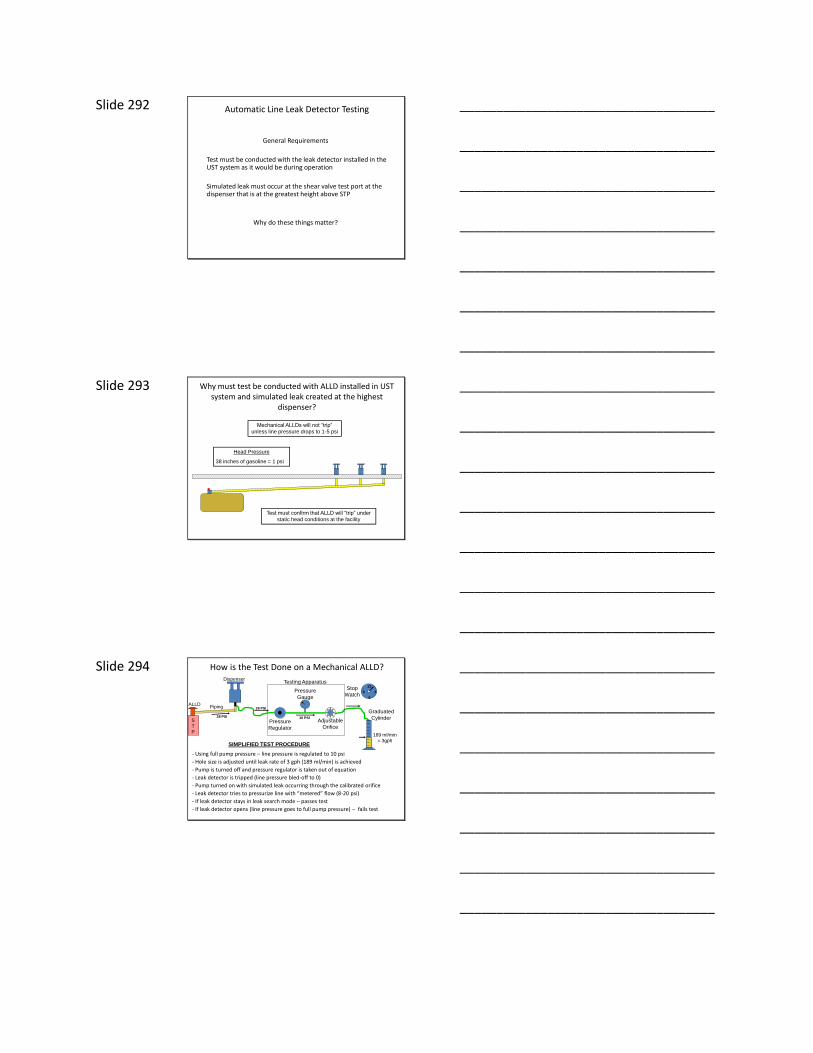
Slide 292 Automatic Line Leak Detector Testing
General Requirements
Test must be conducted with the leak detector installed in the UST system as it would be during operation
Simulated leak must occur at the shear valve test port at the dispenser that is at the greatest height above STP
Why do these things matter?
___________________________________
___________________________________
___________________________________
___________________________________
___________________________________
___________________________________
___________________________________
Slide 293 Why must test be conducted with ALLD installed in UST system and simulated leak created at the highest
dispenser?
Head Pressure
38 inches of gasoline = 1 psi
Mechanical ALLDs will not “trip”
unless line pressure drops to 1-5 psi
Test must confirm that ALLD will “trip” under
static head conditions at the facility
___________________________________
___________________________________
___________________________________
___________________________________
___________________________________
___________________________________
___________________________________
Slide 294 How is the Test Done on a Mechanical ALLD?
10 PSIPressure
Regulator
Adjustable
Orifice
Pressure
Gauge
Graduated
Cylinder
189 ml/min
= 3gph
3
12
9
6
Stop
Watch
Piping
- Using full pump pressure – line pressure is regulated to 10 psi
- Hole size is adjusted until leak rate of 3 gph (189 ml/min) is achieved
- Pump is turned off and pressure regulator is taken out of equation
- Leak detector is tripped (line pressure bled-off to 0)
- Pump turned on with simulated leak occurring through the calibrated orifice
- Leak detector tries to pressurize line with “metered” flow (8-20 psi)
- If leak detector stays in leak search mode – passes test
- If leak detector opens (line pressure goes to full pump pressure) – fails test
28 PSI
28 PSI
SIMPLIFIED TEST PROCEDURE
S
T
P
ALLD
Testing ApparatusDispenser
___________________________________
___________________________________
___________________________________
___________________________________
___________________________________
___________________________________
___________________________________
Slide 295 Automatic Line Leak Detector Testing
How long must the mechanical ALLD remain in the leak search
mode?
5 seconds?30 seconds?3 minutes?
Longer?
ALLD must stay “tripped” indefinitely
___________________________________
___________________________________
___________________________________
___________________________________
___________________________________
___________________________________
___________________________________
Slide 296 3 GPH @ 10 PSI WITHIN 1 HOUR
Where did the 3 gph rate come from?
Originally was 2 gph - manufacturers wanted 3 to ensure could meet 95% probability of detection
Where did the 10 psi pressure come from?
At the time, this was the test pressure that the “typical” leak detectors operated at
Where did the 1 hour time frame come from?
- Pressurized piping requires close monitoring
- Was thought devices would monitor continuously or test cycles (pump on/off) would occur frequently
___________________________________
___________________________________
___________________________________
___________________________________
___________________________________
___________________________________
___________________________________
Slide 297 3 GPH @ 10 PSI
Testing to this standard does not necessarily mean that the leak detector is capable of seeing a 3 gph leak
Only if the test pressure happens to be 10 psi (or less) does the test confirm the leak detector can see a 3 gph leak
If the test pressure is greater than 10 psi then the actual leak that is simulated during the test is greater than 3 gph
___________________________________
___________________________________
___________________________________
___________________________________
___________________________________
___________________________________
___________________________________

Slide 298 Hole size stays the sameIncrease the pressure – Increase the leak rate
10 psi
15 psi
3 gph
3.8 gph
30 psi
30 psi
Hole Size
= 0.1
Hole Size
= 0.1
FLOW
___________________________________
___________________________________
___________________________________
___________________________________
___________________________________
___________________________________
___________________________________
Slide 299 WITHIN 1 HOUR
When is a mechanical leak detector actually capable of detecting a leak?
Once the line is fully pressurized the leak detector will stay open unless the line pressure drops to near zero
What “normal” conditions are needed for the line pressure to drop to near zero? 1. No one is pumping gas for a period of time
2. A large leak is occurring
3. Weak pump with many nozzles open
4. Other mechanical problems (bad check valve, etc…)
This means that if a leak occurs in the piping during operation, the leak detector will never see it unless the leak is great enough to allow the line pressure to drop to near 0.
___________________________________
___________________________________
___________________________________
___________________________________
___________________________________
___________________________________
___________________________________
Slide 300 Automatic Line Leak Detector Testing
How is the Test Done on Electronic ALLD?
1. Line pressure is regulated to 10 psi
2. Orifice size is adjusted until leak rate of 3 gph (189 ml/min) is achieved
3. Pressure regulator is taken out of equation
4. Electronic ALLD is made to conduct test (normally, just means all nozzles are hung-up)
5. Time allowed for leak detector to cycle through testing
6. Confirm that console alarms and/or shuts down pump
7. If it does not alarm or shut down – It fails the test
___________________________________
___________________________________
___________________________________
___________________________________
___________________________________
___________________________________
___________________________________
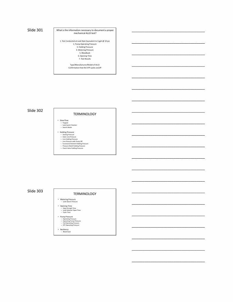
Slide 301 What is the information necessary to document a proper mechanical ALLD test?
1. Test Conducted at Leak Rate Equivalent to 3 gph @ 10 psi
2. Pump Operating Pressure
3. Holding Pressure
4. Metering Pressure
5. Bleedback
6. Opening Time
7. Test Results
Type/Manufacturer/Model of ALLD
Confirmation that the STP cycles on/off
___________________________________
___________________________________
___________________________________
___________________________________
___________________________________
___________________________________
___________________________________
Slide 302 TERMINOLOGY
• Slow Flow– Tripped
– Leak Search Position
– Search Mode
• Holding Pressure– Seating Pressure
– Static Line Pressure
– Line Holding Pressure
– Line Pressure with Pump Off
– Functional Element Holding Pressure
– Pressure Relief Holding Pressure
– Check Valve Holding Pressure
___________________________________
___________________________________
___________________________________
___________________________________
___________________________________
___________________________________
___________________________________
Slide 303 TERMINOLOGY
• Metering Pressure– Leak Search Pressure
• Opening Time– Step-through Time– Leak Detector Open Time– Cycle Time
• Pump Pressure– Operating Pressure– Operating Pump Pressure– Full Operating Pressure– STP Operating Pressure
• Resiliency– Bleed-back
___________________________________
___________________________________
___________________________________
___________________________________
___________________________________
___________________________________
___________________________________

Slide 304
Why is there no
test leak rate ?
___________________________________
___________________________________
___________________________________
___________________________________
___________________________________
___________________________________
___________________________________
Slide 305
___________________________________
___________________________________
___________________________________
___________________________________
___________________________________
___________________________________
___________________________________
Slide 306
___________________________________
___________________________________
___________________________________
___________________________________
___________________________________
___________________________________
___________________________________

Slide 307
___________________________________
___________________________________
___________________________________
___________________________________
___________________________________
___________________________________
___________________________________
Slide 308
___________________________________
___________________________________
___________________________________
___________________________________
___________________________________
___________________________________
___________________________________
Slide 309
___________________________________
___________________________________
___________________________________
___________________________________
___________________________________
___________________________________
___________________________________

Slide 310
___________________________________
___________________________________
___________________________________
___________________________________
___________________________________
___________________________________
___________________________________
Slide 311
___________________________________
___________________________________
___________________________________
___________________________________
___________________________________
___________________________________
___________________________________
Slide 312 Chapter 12: Corrosion Control
40 CFR Part 280
– Any metallic component that routinely contains product and is in contact with the soil must be protected from corrosion
• Routinely contains product – tank, product line, flex connectors, product piping tees, ells, nipples
• Does not routinely contain product – Vent lines, risers (fill, ATG, STP)– Remote fills?– STP head?– Spill buckets?
• In contact with the “soil” (soil = electrolyte)– Double-walled steel tanks?
___________________________________
___________________________________
___________________________________
___________________________________
___________________________________
___________________________________
___________________________________

Slide 313 Chapter 12: Corrosion Control
What is Corrosion?
• Corrosion is an electrochemical process
• Metals corrode in an attempt to achieve balance of energy
• Steel is a highly refined product of iron (energy added during refining)
• Steel wants to revert back to its original state (iron oxide = rust)
• When metals oxidize electrons are given up
• To simplify – corrosion occurs when/where electrons leave the metal
• If we can provide an excess source of electrons – oxidation will not occur
___________________________________
___________________________________
___________________________________
___________________________________
___________________________________
___________________________________
___________________________________
Slide 314 Chapter 12: Corrosion Control
Corrosion Cell
4 components necessary for corrosion to occur
1. Cathode
2. Anode
3. Electrolyte
4. Metallic Path
___________________________________
___________________________________
___________________________________
___________________________________
___________________________________
___________________________________
___________________________________
Slide 315 A COMMON DRY CELL BATTERY
IS A GALVANIC CORROSION CELL
CARBON ROD
(CATHODE)
ZINC CASE
(ANODE)
MOIST PASTE
(ELECTROLYTE)
WIRE
(CONDUCTOR)
CONVENTIONAL
CURRENT
Zn++
H+
OH-
OH-
___________________________________
___________________________________
___________________________________
___________________________________
___________________________________
___________________________________
___________________________________

Slide 316 Chapter 12: Corrosion Control
How is corrosion of steel and metallic structures controlled?
• Coatings – Epoxy coatings (sti-P3 tanks)– Field applied coatings– Field applied wraps/tapes
• Isolation – Nylon bushings (sti-P3 tanks)– Isolation unions/bushings (piping)– “Boots” on flex connectors– Composite tank construction
• Cathodic Protection– Galvanic (sti-P3 tanks)– Impressed Current
___________________________________
___________________________________
___________________________________
___________________________________
___________________________________
___________________________________
___________________________________
Slide 317 Chapter 12: Corrosion Control
How is corrosion of steel and metallic structures controlled?
– Cathodic Protection
• Galvanic – Metal of higher electro potential is connected to steel
– Typical anodes are zinc/magnesium– Anode provides source of excess electrons
• Impressed Current – DC current is supplied to provide the excess source of electrons
– Anodes are typically Mixed Metal Oxide or Cast Iron
___________________________________
___________________________________
___________________________________
___________________________________
___________________________________
___________________________________
___________________________________
Slide 318 Relative Energy Levels of MetalsMeasured relative to a Cu/CuSO reference cell
-1600
+1200GOLD
- 100COPPER
-1000ALUMINUM
MAGNESIUM
-1100ZINC
+ 400CARBON
+ 500SILVER
+ 900PLATINUM
- 600STEEL
Active (Corrodes Easily)
Passive (Stable)
Anodic
Cathodic
___________________________________
___________________________________
___________________________________
___________________________________
___________________________________
___________________________________
___________________________________

Slide 319 Chapter 12: Corrosion Control
Why do I need cathodic protection on a sti-P3 tank?
• Coated – Epoxy
• Isolated – Nylon bushings – no other metals connected
• Steel is not a homogenous materialEach “crystal” of steel could have a slightly different potential
___________________________________
___________________________________
___________________________________
___________________________________
___________________________________
___________________________________
___________________________________
Slide 320 Chapter 12: Corrosion Control
Qualifications
CP Tester – Certification from NACE, STI, ALPEC, GTEC
CP Expert – NACE Corrosion Specialist or Cathodic Protection Specialist
CP Expert must design “new” field installed CP systems
• Plans and specs sealed by corrosion expert of AL PE with CP experience must be approved by ADEM
Repairs of existing CP systems must follow a recognized industry standard
• NACE, STI
___________________________________
___________________________________
___________________________________
___________________________________
___________________________________
___________________________________
___________________________________
Slide 321 Chapter 12: Corrosion Control
Installation – Sacrificial Anodes
– Bury deep enough to reach “wet” soil
– The top of the anode should be at least 2-3 feet below grade
– Anodes should be buried 3-5 feet away from the structure to be protected and in the native soil (not the backfill)
– Always soak the anodes with water after installation and before burial is completed
– The size, number and location of anodes needed depends on several different factors and must be calculated based on measurements that are site specific
– Isolation of the structure you are protecting with sacrificial anodes is critical
• Without isolation, may require too many anodes or anodes may not last
___________________________________
___________________________________
___________________________________
___________________________________
___________________________________
___________________________________
___________________________________

Slide 322 Chapter 12: Corrosion Control
Installation – Impressed Current
– All the same guidelines as for sacrificial anodes
– Anodes need to be backfilled with coke breeze
– The size of the rectifier needed is calculated based on several measurements that are site specific
– The positive side of the rectifier is connected to the anodes
– The negative side of the rectifier is connected to the structure
– Important that wires are not nicked and underground splices should be avoided if possible
___________________________________
___________________________________
___________________________________
___________________________________
___________________________________
___________________________________
___________________________________
Slide 323 Chapter 12: Corrosion Control
Testing Cathodic Protection
– Both Impressed Current and Galvanic tested every 3 years (Impressed Current “monitored” every 60 days - system must be operated continuously)
– Must test within 6 months of cathodic protection system installation and/or repair
– High impedance voltmeter• Negative connected to the reference cell and Positive to the structure
– Copper-Copper Sulfate reference cell is placed in the backfill• 3 test points (ref. cell at each end of the tank and in the middle)• Piping generally tested at each end
___________________________________
___________________________________
___________________________________
___________________________________
___________________________________
___________________________________
___________________________________
Slide 324 Chapter 12: Corrosion Control
Testing Cathodic Protection
– Criteria for Passing
• -850 mV (on) – P3 tanks and most galvanic systems
• -850 mV (off) – Impressed current systems
• 100 mv shift – Impressed current systems
___________________________________
___________________________________
___________________________________
___________________________________
___________________________________
___________________________________
___________________________________

Slide 325 Chapter 12: Corrosion Control
Testing Equipment Calibration
– Voltmeters should be calibrated annually
• Send to manufacturer
– Reference Cells must be calibrated at least annually but it depends on how much you use it (could need to be calibrated monthly)
• Calibration is accomplished by comparing field reference cell with one that has never been in the field
___________________________________
___________________________________
___________________________________
___________________________________
___________________________________
___________________________________
___________________________________
Slide 326 Chapter 12: Corrosion Control
Repairs
– Cathodic Protection systems must be tested after “repairs” (generally within 6 months)
• Repairs does not just apply to the Cathodic Protection system itself
• Virtually any excavation at the site can potentially damage/destroy an impressed current system
• Many repairs to UST systems that have galvanic cathodic protection can potentially damage/destroy cathodic protection system
___________________________________
___________________________________
___________________________________
___________________________________
___________________________________
___________________________________
___________________________________
Slide 327 Chapter 13: Tank System Testing
Deflection Testing
– Required for FRP tanks (usually part of the manufacturers installation checklist)
• Tank inside diameter is measured before backfilling begins
• Measured again after backfilling but before paving occurs
• May also be required as backfilling progresses
• Beginning and ending measurements are compared
• Must be within manufacturers allowable range
___________________________________
___________________________________
___________________________________
___________________________________
___________________________________
___________________________________
___________________________________
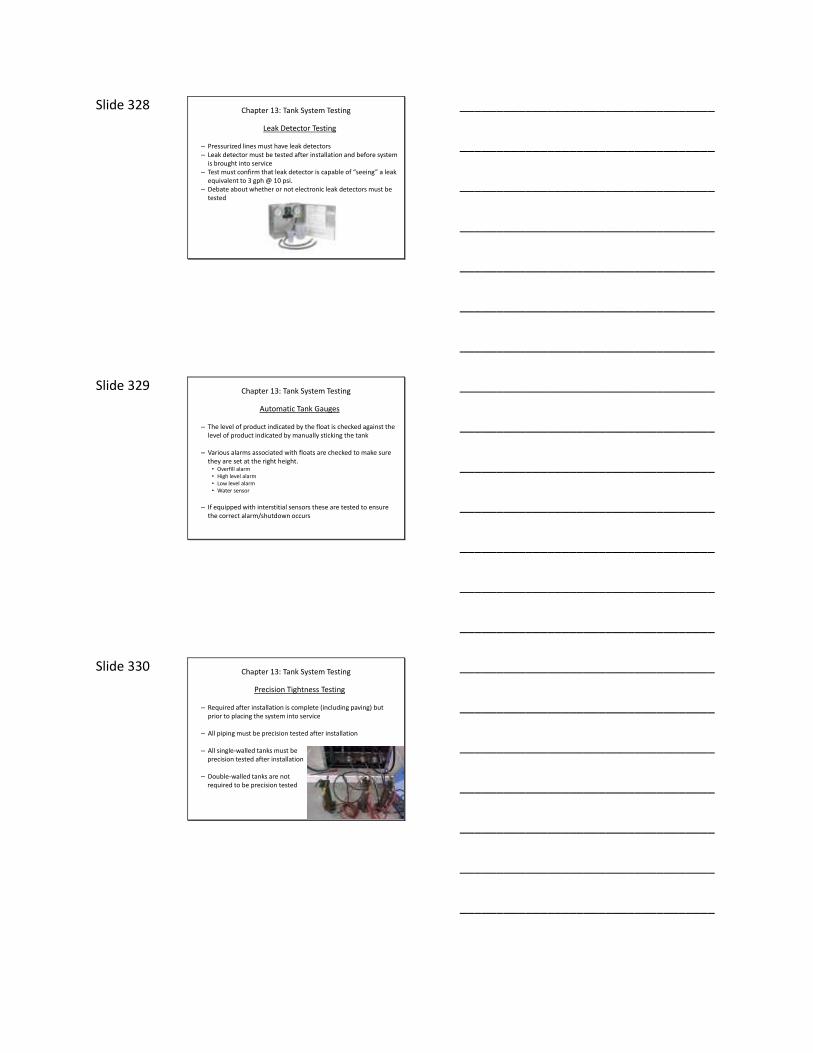
Slide 328 Chapter 13: Tank System Testing
Leak Detector Testing
– Pressurized lines must have leak detectors– Leak detector must be tested after installation and before system
is brought into service– Test must confirm that leak detector is capable of “seeing” a leak
equivalent to 3 gph @ 10 psi.– Debate about whether or not electronic leak detectors must be
tested
___________________________________
___________________________________
___________________________________
___________________________________
___________________________________
___________________________________
___________________________________
Slide 329 Chapter 13: Tank System Testing
Automatic Tank Gauges
– The level of product indicated by the float is checked against the level of product indicated by manually sticking the tank
– Various alarms associated with floats are checked to make sure they are set at the right height.
• Overfill alarm• High level alarm• Low level alarm• Water sensor
– If equipped with interstitial sensors these are tested to ensure the correct alarm/shutdown occurs
___________________________________
___________________________________
___________________________________
___________________________________
___________________________________
___________________________________
___________________________________
Slide 330 Chapter 13: Tank System Testing
Precision Tightness Testing
– Required after installation is complete (including paving) but prior to placing the system into service
– All piping must be precision tested after installation
– All single-walled tanks must be precision tested after installation
– Double-walled tanks are notrequired to be precision tested
___________________________________
___________________________________
___________________________________
___________________________________
___________________________________
___________________________________
___________________________________
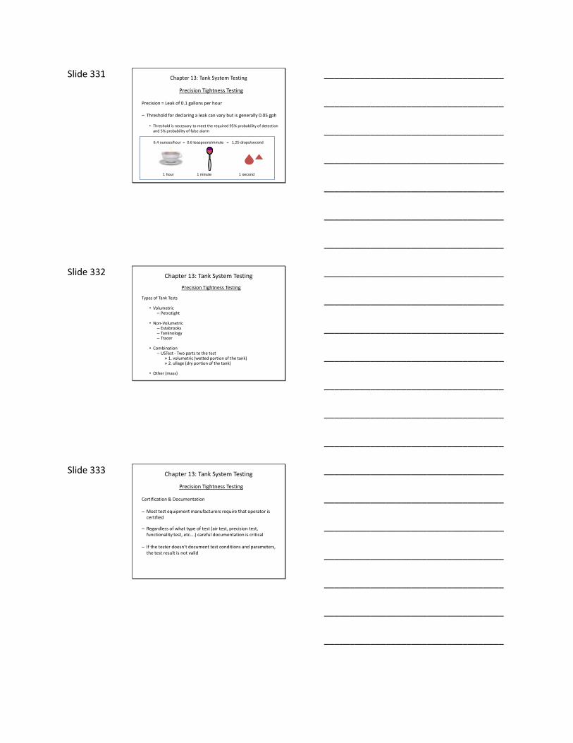
Slide 331 Chapter 13: Tank System Testing
Precision Tightness Testing
Precision = Leak of 0.1 gallons per hour
– Threshold for declaring a leak can vary but is generally 0.05 gph
• Threshold is necessary to meet the required 95% probability of detection and 5% probability of false alarm
6.4 ounces/hour = 0.6 teaspoons/minute = 1.25 drops/second
1 hour 1 minute 1 second
___________________________________
___________________________________
___________________________________
___________________________________
___________________________________
___________________________________
___________________________________
Slide 332 Chapter 13: Tank System Testing
Precision Tightness Testing
Types of Tank Tests
• Volumetric– Petrotight
• Non-Volumetric– Estabrooks– Tanknology– Tracer
• Combination– USTest - Two parts to the test
» 1. volumetric (wetted portion of the tank)» 2. ullage (dry portion of the tank)
• Other (mass)
___________________________________
___________________________________
___________________________________
___________________________________
___________________________________
___________________________________
___________________________________
Slide 333 Chapter 13: Tank System Testing
Precision Tightness Testing
Certification & Documentation
– Most test equipment manufacturers require that operator is certified
– Regardless of what type of test (air test, precision test, functionality test, etc….) careful documentation is critical
– If the tester doesn’t document test conditions and parameters, the test result is not valid
___________________________________
___________________________________
___________________________________
___________________________________
___________________________________
___________________________________
___________________________________

Slide 334
___________________________________
___________________________________
___________________________________
___________________________________
___________________________________
___________________________________
___________________________________