instructor :- rajveer singh college:- invertis institute of engineering and management. unit - 1
TRANSCRIPT

Mobile ComputingECS-087
Instructor :- Rajveer SinghCollege:- Invertis Institute of engineering and management.
UNIT - 1

Overview
Introduction of Mobile Computing Issues in mobile computing Overview of wireless telephony:
cellular concept GSM (channel structure, location management:
HLR-VLR, hierarchical, handoffs) CDMA, GPRS.

Wireless Communication
Accessing a network or other communication partner without using wire.
The wire is replaced by the transmission of electromagnetic waves/signals.

Communication Possibilities
Fixed & Wired1. Desktop computer in an office
2. The devices use fixed networks for performance reasons.
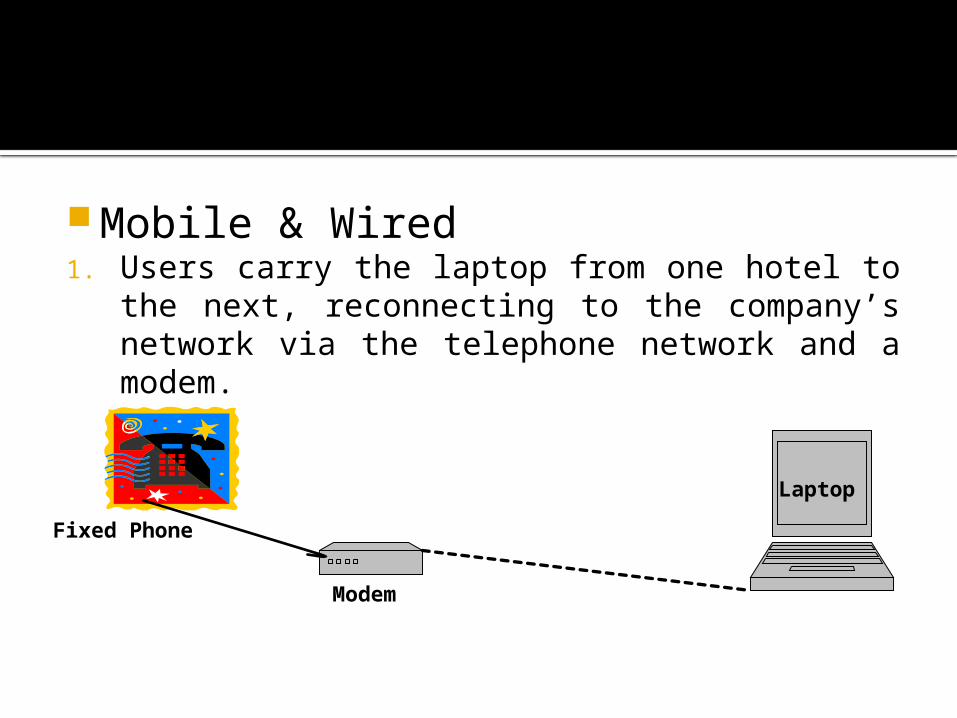
Mobile & Wired1. Users carry the laptop from one hotel to the
next, reconnecting to the company’s network via the telephone network and a modem.
Modem
Laptop
Fixed Phone
Fixed & Wireless
Example:- Ad-hoc networks (in trade show)
Mobile & Wireless
Example:- GSM/CDMA System

Wireless systems operate by transmission through space.
Major problems:- The channel over which communication takes
place is time varying (nodes move rapidly).
Interference between multiple users using a common communication medium.
Wireless communication devices
Mobile (eg. cell phones, radio transceivers mounted on cars, aircrafts, etc)
Or
Stationary (eg. base stations(BTS/BS) of cellular networks).

Signals
Signals are physical representation of data.
In a communication system, Data is exchanged through signals.
Physical Layer of ISO/OSI reference model converts the data(bits), into signals, and vice-versa.
In a wireless channel, signals are transmitted via electromagnetic radiations which are analog in nature.

Fig. A Simple Wireless Network Model

The most interesting types of signals for radio transmission are periodic signals, especially sine waves as carriers.
The general function of a sine wave is:g(t) = At sin(2 π ftt + φt)
Signal parameters are:- amplitude At, the
frequency ft, and the phase shift φt.

Time Domain, Frequency domain and Phase domain representation of a Signal
Third figure shows the amplitude M of a signal and its phase φ in polar coordinates. (The length of the vector represents the amplitude, the angle the phase shift.)

Signal propagation
Transmission range• communication possible• low error rate Detection range•detection of the signal
possible• no communication possible Interference range• signal may not be detected •signal adds to the
background noise
Signal propagation
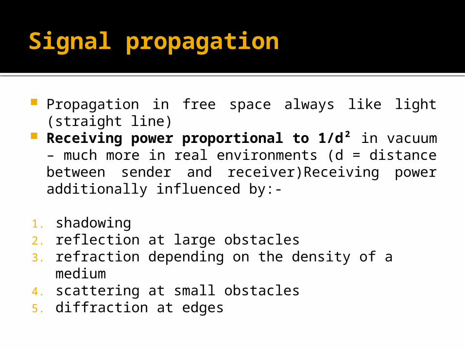
Propagation in free space always like light (straight line)
Receiving power proportional to 1/d² in vacuum – much more in real environments (d = distance between sender and receiver)Receiving power additionally influenced by:-
1. shadowing2. reflection at large obstacles3. refraction depending on the density of a medium4. scattering at small obstacles5. diffraction at edges
Path loss of radio signals
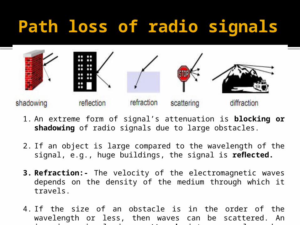
1. An extreme form of signal’s attenuation is blocking or shadowing of radio signals due to large obstacles.
2. If an object is large compared to the wavelength of the signal, e.g., huge buildings, the signal is reflected.
3. Refraction:- The velocity of the electromagnetic waves depends on the density of the medium through which it travels.
4. If the size of an obstacle is in the order of the wavelength or less, then waves can be scattered. An incoming signal is scattered into several weaker outgoing signals.

In free space radio signals propagate as light does, i.e., they follow a straight line.
Even if no matter exists between the sender and the receiver (i.e., if there is a vacuum), the signal still experiences the free space loss.
The received power Pr is proportional to 1/d2 with d being the distance between sender and receiver.
S = 4*Π *d2

Multi-path propagation
Signal can take many different paths between sender and receiver due to reflection, scattering, diffraction, etc..

Effects of mobility
Channel characteristics change over time and location
• signal paths change• different delay variations of different signal parts• different phases of signal parts• quick changes in the power received (short term
fading)
Additional changes in
• obstacles further away• slow changes in the averagepower received long term fading

Multiplexing
Multiplexing in 4 dimensions• space (si)• time (t)• frequency (f)• code (c)
Goal: multiple use of a shared medium
Important: guard spaces needed

Frequency Division Multiplexing
Separation of the whole spectrum into smaller frequency bands.
A channel gets a certain band of the spectrum for the whole time.
Advantages no dynamic coordination necessary works also for analog signals
Disadvantages waste of bandwidth if the traffic is distributed unevenly inflexible

FDM..
Fig. Frequency division multiplexing (FDM)

FDM…
This scheme is used for radio stations within the same region, where each radio station has its own frequency.
Assigning a separate frequency for each possible communication scenario would be a tremendous waste of (scarce) frequency resources.
The fixed assignment of a frequency to a sender makes the scheme very inflexible and limits the number of senders.

Time division multiplexing (TDM)
A channel gets the whole spectrum for a certain amount of time.
Advantages• only one carrier in the medium at any time• throughput high even for many users
Disadvantages• precise synchronization necessary

TDM..
Fig. Time division multiplexing (TDM)

Time and frequency multiplex
Combination of both methods A channel gets a certain frequency band for a
certain amount of time
Example: GSM Network
Advantages• better protection against tapping• protection against frequency selective interferencebut: precise coordination required Two senders will interfere as soon as they select
the same frequency at the same time.

Fig. Frequency and time division multiplexing combined

Code division multiplexing
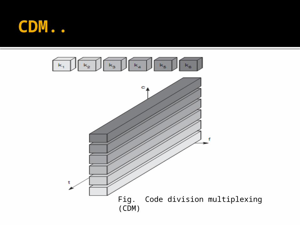
Each channel has a unique code All channels use the same spectrum at the same time
Advantages• bandwidth efficient• no coordination and synchronization necessary• good protection against interference and tapping
Disadvantages• varying user data rates• more complex signal regeneration
Implemented using spread spectrum technology
CDM..
Fig. Code division multiplexing (CDM)

Space division multiplexing
Each channel assigned a fixed space.
Example:- In highway each lane for each car. Many radio stations around the world can use the
same frequency without interference.

SDM..
Fig. Space Division Multiplexing

Modulation
Modulation is the process of facilitating the transfer of information over a medium.
or
The process of converting information (voice) so that it can be successfully sent through a medium (wire or radio waves) is called modulation.

Digital Modulation
Digital modulation is required if digital data has to be transmitted over a medium (wireless) that only allows for analog transmission.
In wireless networks, digital transmission cannot be used.
So, the binary bit-stream has to be translated into an analog signal(Baseband Signal) first.
The three basic methods for this translation are.1. Amplitude Shift Keying (ASK) 2. Frequency Shift Keying (FSK)3. Phase Shift Keying (PSK).
Modulation of digital signals known as Shift Keying.
All the techniques vary a parameter (amplitude, phase, or frequency) of a sinusoid to represent the information which we wish to send.
Modulation is a process of mapping such that it takes the voice signals, converts it into some aspect of sine wave and then transmit the sine wave, leaving behind the actual voice.
The sine wave on receiver side remapped back to a near copy of original voice.
Sine wave is called carrier wave.

Analog Modulation
Wireless transmission requires an additional modulation, an analog modulation, it shifts the center frequency of the baseband signal generated by the digital modulation up to the radio carrier, so that it can be sent to the receiver.
Three types of analog modulation:-1. Amplitude Modulation(AM)2. Phase Modulation(PM)3. Frequency Modulation(FM)
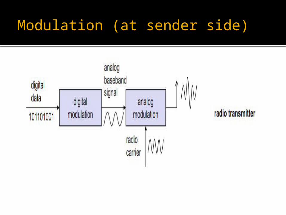
Modulation (at sender side)

Demodulation and data reconstruction in a receiver

Amplitude Shift Keying
The two binary values, 1 and 0, are represented by two different amplitudes.
Very simple Low bandwidth requirements Very susceptible to interference

Frequency Shift Keying
Needs larger bandwidth.
The simplest form of FSK, also called Binary FSK (BFSK), assigns one frequency f1 to the binary 1 and another frequency f2 to the binary 0.
To avoid sudden changes in phase, special frequency modulators with continuous phase modulation, (CPM) can be used. Sudden changes in phase cause high frequencies, which is an undesired side-effect.

Phase Shift Keying (PSK)
PSK uses shifts in the phase of a signal to represent data.
A phase shift of 180° as the 0 follows the 1 (the same happens as the 1 follows the 0).
It is also called Binary PSK (BPSK). More complex. Robust against interference.
Advanced Frequency Shift Keying (AFSK)
A famous FSK scheme used in many wireless systems is minimum shift keying (MSK).
MSK is basically BFSK without abrupt phase changes, i.e., it belongs to CPM.
AFSK……
Data bits are separated into even and odd bits.
The duration of each bit being doubled.
The scheme also uses two frequencies:
f1 - the lower frequency f2 - the higher frequency
Such that:- f2 = 2f1

Lower or Higher frequency is chosen (either inverted or non-inverted) to generate the MSK signal:-
If the even and the odd bit are both 0, then the higher frequency f2 is inverted.
If the even bit is 1, the odd bit 0, then the lower frequency f1 is inverted.
If the even bit is 0 and the odd bit is 1, f1 is taken without changing the phase.
If both bits are 1 then the original f2 is taken. Even Bit
Odd Bit
Frequency
0 0 `F2
1 0 `F1
0 1 F1
1 1 F2
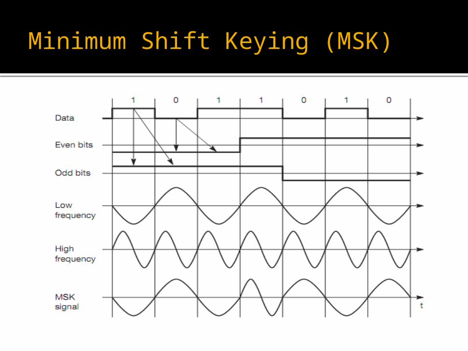
Minimum Shift Keying (MSK)

Spread Spectrum
Spreading the bandwidth needed to transmit data.
Advantage:- Resistance to narrowband interference. Many users can simultaneously use the same
bandwidth without significantly interfering with one another.
Power Density
Narrow Band Signal
Idealized narrowband signal from a sender of user data

Since narrowband interference effects only a small portion of the spread spectrum signal.
Narrowband interference can easily be removed through notch filtering without much loss of information.
Resistance to multipath fading is another advantage.

Spreads the signal i.e., convert the narrowband signal into a broadband signal.
The power level of the spread signal can be much lower than that of the original narrowband signal without losing data.
Power density is same in both figure (i & ii).

During transmission, narrowband and broadband interference add to the signal.
User Signal
Broadband Interference
Narrowband Interference

Receiver now dispread the signal, converting the spread user signal into a narrowband signal again, while spreading the narrowband interference and leaving the broadband interference.

Receiver applies a band-pass filter to cut off frequencies left and right of the narrowband signal.
Receiver can reconstruct the original data because the power level of the user signal is high enough, than the remaining interference.
Spreading the spectrum can be achieved in two different ways:-
1. Direct Sequence Spread Spectrum(DSSS)
2. Frequency Hopping Spread Spectrum(FHSS)

Direct Sequence Spread Spectrum(DSSS)
Take a user bit stream and perform an (XOR) with a so-called chipping sequence.
User bit has a duration tb
Chipping sequence has a duration tc

The spreading factor s = tb/tc determines the bandwidth of the resulting signal.
If the original signal needs a bandwidth w, the resulting signal needs s·w after spreading.
Example a user signal with a bandwidth of 1 MHz. Spreading with the above 11-chip Barker code would result in a signal with 11 MHz bandwidth.
The radio carrier then shifts this signal to the carrier frequency. This signal is then transmitted.


The first step in the receiver involves demodulating the received signal.
This is achieved using the same carrier as the transmitter reversing the modulation and results in a signal with approximately the same bandwidth as the original spread spectrum signal.

User Data 01
11-chip Barker code 10110111000
Results in the spread ‘signal’ 1011011100001001000111
On the receiver side, this ‘signal’ is XORed bit-wise after demodulation with the same Barker code as chipping sequence.
This results in the sum of products equal to 0 for the first bit and to 11 for the second bit.
The decision unit can now map the first sum (=0) to a binary 0, the second sum (=11) to a binary 1 – this constitutes the original user data.

Frequency hopping spread spectrum
Total available bandwidth is split into many channels of smaller bandwidth plus guard spaces between the channels.
Transmitter and receiver stay on one of these channels for a certain time and then hop to another channel.
This system implements FDM and TDM.
The pattern of channel usage is called the hopping sequence.
The time spend on a channel with a certain frequency is called the dwell time.

FHSS comes in two variants, slow and fast hopping.
Slow Hopping:- The transmitter uses one frequency for several bit
periods. Example:- 3 bits/hop
Fast Hopping:- The transmitter changes the frequency several times
during the transmission of a single bit. 3 Hops/bit
Example of an FHSS system is Bluetooth. Bluetooth performs 1,600 hops per second and uses
79 hop carriers equally spaced with 1 MHz in the 2.4 GHz ISM band.

Cellular systems
Implements space division multiplex.
Base station covers a certain transmission area (cell).
Mobile stations communicate only via the base station.
Advantages of cell structures Higher capacity, higher number of users Less transmission power needed More robust, decentralized Base station deals with interference, transmission
area etc. locally.
Problems Fixed network needed for the base stations Handover (changing from one cell to another)
necessary Interference with other cells.
Cell sizes from some 100 m in cities to, e.g., 35 km on the rural area.
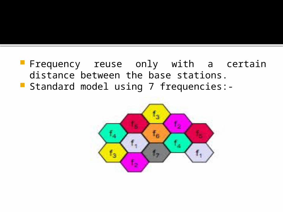
Frequency reuse only with a certain distance between the base stations.
Standard model using 7 frequencies:-
Advantages of cellular systems with small cells
Higher capacity:-Implementing SDM allows frequency reuse. If one transmitter is far away from another, i.e., outside the interference range, it can reuse the same frequencies.
Less transmission power:- A receiver far away from a base station would need much more transmit power.
Local interference only:- Long distances between sender and receiver results in even more interference problems.
Robustness:- Cellular systems are decentralized and so, more robust against the failure of single components.

Disadvantages:-
Infrastructure needed:- Cellular systems need a complex infrastructure to connect all base stations.
Handover needed:- The mobile station has to perform a handover when changing from one cell to another.
Frequency planning:- To avoid interference between transmitters using the same frequencies, frequencies have to be distributed carefully.

Frequency planning

Frequency planning
Fixed frequency assignment: GSM Certain frequencies are assigned to a certain cell Problem: different traffic load in different cells. Cells with more traffic are dynamically allotted
more frequencies. This scheme is known as borrowing channel allocation (BCA).
Dynamic frequency assignment: Base station chooses frequencies depending on the
frequencies already used in neighbor cells. More capacity in cells with more traffic. Assignment can also be based on interference
measurements.

CELL Breathing
In CDM, users are separated through the code they use, not through the frequency.
Cell planning faces another problem – the cell
size depends on the current load.
Accordingly, CDM cells are commonly said to ‘breathe’.
While a cell can cover a larger area under a light load, it shrinks if the load increases.
The reason for this is the growing noise level if more users are in a cell.
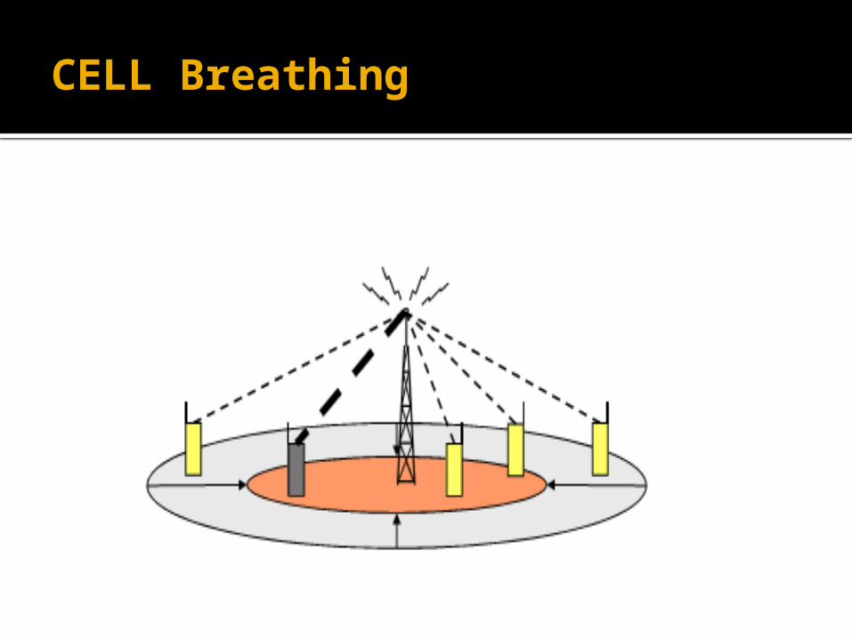
CELL Breathing
