instructions model avoz-d6-b 1000 volt, 200 …ed2.pdf · exceeding the applicable specifications...
TRANSCRIPT

INSTRUCTIONS
MODEL AVOZ-D6-B
1000 VOLT, 200 AMP
PULSE GENERATOR
WITH IEEE 488.2 AND RS-232 CONTROL
SERIAL NUMBER: ____________
A V T E C H E L E C T R O S Y S T E M S L T D .N A N O S E C O N D W A V E F O R M E L E C T R O N I C S
S I N C E 1 9 7 5
P.O. BOX 265OGDENSBURG, NYU.S.A. 13669-0265
TEL: 888-670-8729 (USA & Canada) or +1-613-686-6675 (Intl)FAX: 800-561-1970 (USA & Canada) or +1-613-686-6679 (Intl)
[email protected] - http://www.avtechpulse.com/
X BOX 5120, LCD MERIVALEOTTAWA, ONTARIOCANADA K2C 3H5

WARRANTY
Avtech Electrosystems Ltd. warrants products of its manufacture to be freefrom defects in material and workmanship under conditions of normal use. If,within one year after delivery to the original owner, and after prepaid return bythe original owner, this Avtech product is found to be defective, Avtech shall atits option repair or replace said defective item. This warranty does not apply tounits which have been dissembled, modified or subjected to conditionsexceeding the applicable specifications or ratings. This warranty is the extent ofthe obligation assumed by Avtech with respect to this product and no otherwarranty or guarantee is either expressed or implied.
TECHNICAL SUPPORT
Phone: 888-670-8729 (USA & Canada) or +1-613-686-6675 (International)Fax: 800-561-1970 (USA & Canada) or +1-613-686-6679 (International)
E-mail: [email protected] Wide Web: http://www.avtechpulse.com
2

TABLE OF CONTENTS
WARRANTY......................................................................................................................2
TECHNICAL SUPPORT...................................................................................................2
TABLE OF CONTENTS....................................................................................................3
INTRODUCTION...............................................................................................................5
AVAILABLE OPTIONS.....................................................................................................6
SPECIFICATIONS............................................................................................................7
REGULATORY NOTES....................................................................................................8
FCC PART 18..........................................................................................................................8
EC DECLARATION OF CONFORMITY..................................................................................8
DIRECTIVE 2011/65/EU (RoHS).............................................................................................9
DIRECTIVE 2002/96/EC (WEEE)............................................................................................9
FIRMWARE LICENSING.......................................................................................................10
INSTALLATION..............................................................................................................11
VISUAL CHECK....................................................................................................................11
POWER RATINGS................................................................................................................11
CONNECTION TO THE POWER SUPPLY...........................................................................11
PROTECTION FROM ELECTRIC SHOCK...........................................................................12
ENVIRONMENTAL CONDITIONS........................................................................................13
LABVIEW DRIVERS..............................................................................................................13
FUSES.............................................................................................................................14
AC FUSE REPLACEMENT...................................................................................................14
DC FUSE REPLACEMENT...................................................................................................15
FUSE RATINGS....................................................................................................................15
FRONT PANEL CONTROLS..........................................................................................16
REAR PANEL CONTROLS............................................................................................18
GENERAL INFORMATION............................................................................................20
BASIC PULSE CONTROL....................................................................................................20
TRIGGER MODES................................................................................................................22
PULSE WIDTH MODES........................................................................................................22
GATING MODES...................................................................................................................22
AMPLITUDE DECAY TIME...................................................................................................23
THE LOAD AND OUTPUT MODULE....................................................................................23
PREVENTING OUTPUT STAGE FAILURE..........................................................................24
3

OPERATIONAL CHECK.................................................................................................25
PROGRAMMING YOUR PULSE GENERATOR...........................................................28
KEY PROGRAMMING COMMANDS....................................................................................28
ALL PROGRAMMING COMMANDS.....................................................................................29
MECHANICAL INFORMATION......................................................................................31
TOP COVER REMOVAL.......................................................................................................31
RACK MOUNTING................................................................................................................31
ELECTROMAGNETIC INTERFERENCE..............................................................................31
MAINTENANCE..............................................................................................................32
REGULAR MAINTENANCE..................................................................................................32
CLEANING............................................................................................................................32
WIRING DIAGRAMS.......................................................................................................33
WIRING OF AC POWER.......................................................................................................33
WIRING OF DC POWER.......................................................................................................34
PCB 158R3 - LOW VOLTAGE POWER SUPPLY................................................................35
PCB 197G - HIGH-VOLTAGE POWER SUPPLY.................................................................36
PCB 183A-S AND 183A-P CAPACITOR BANKS.................................................................37
PCB 104F - KEYPAD / DISPLAY BOARD, 1/3.....................................................................38
PCB 104F - KEYPAD / DISPLAY BOARD, 2/3.....................................................................39
PCB 104F - KEYPAD / DISPLAY BOARD, 3/3.....................................................................40
MAIN WIRING - POSITIVE (-P) UNITS.................................................................................41
PERFORMANCE CHECK SHEET.................................................................................42 Manual Reference: /fileserver2/officefiles/instructword/avoz/AVOZ-D6-B,ed2.odt.Last modified December 6, 2017.Copyright © 2017 Avtech Electrosystems Ltd, All Rights Reserved.
4

INTRODUCTION
The AVOZ-D6-B is a high performance, GPIB and RS232-equipped pulser generator that features ten identical outputs. These outputs can either be combined to drive a single low-impedance (5 Ohm) load, or can be used separately to drive multiple 50 Ohm loads simultaneously. This unique flexibility makes the AVOZ-D6-B ideal for testing high-current laser diode arrays, as well as testing multiple identical lower-currentdevices (for instance, production testing of attenuators).
The AVOZ-D6-B is capable of generating up to 1000V on each of its ten identical outputs, at repetition rates up to 500 Hz. The pulse width is variable from 1 us to 10 us, and the duty cycle may be as high as 0.05%. Rise and fall times are fixed at less than 200 ns. The AVOZ-D6-B includes an internal trigger source, but it can also be triggered or gated by an external source. A front-panel pushbutton can also be used to trigger theinstrument. The output pulse width can be set to follow an input trigger pulse width.
The ten outputs are all wired to the same point internally, and thus share common timing and amplitude controls. If the ten outputs are connected to a common 5 Ohm load, the AVOZ-D6-B can deliver up to 200 Amps of pulsed current to the load.
An optional output module is available to simplify the connection of a single load to the multiple outputs. Cable kits are also optionally available.
The output voltage polarity depends on the model number:
"-P" units: up to +1000 Volts"-N" units: up to -1000 Volts
The AVOZ-D6-B features front panel keyboard and adjust knob control of the output pulse parameters along with a four line by 40-character backlit LCD display of the output amplitude, pulse width, pulse repetition frequency, and delay. The instrument includes memory to store up to four complete instrument setups. The operator may use the front panel or the computer interface to store a complete “snapshot” of all key instrument settings, and recall this setup at a later time.
The instrument is protected against overload conditions (such as short circuits) by an automatic control circuit. An internal power supply monitor removes the power to the output stage for five seconds if an average power overload exists. After that time, the unit operates normally for one second, and if the overload condition persists, the power is cut again. This cycle repeats until the overload is removed.
This instrument is intended for use in research, development, test and calibration laboratories by qualified personnel.
5

AVAILABLE OPTIONS
-CK10 Option: Cable kit (ten RG-58C/U cables, 5ft/152cm)
-OM10 Option: Output module, with ten input connectors and one output connector.
-R5 Option: Rack-mount kit.
-VXI Option: Adds a rear-panel Ethernet connector, allowing the instrument to be remotely controlled using the VXI-11.3, ssh (secure shell), telnet, and http (web) protocols. In particular, the VXI-11.3 features allows software like LabView to control an instrument using standard VISA communications drivers and network cabling, instead of using old-styleGPIB cabling. (This eliminates the need for a GPIB controller card and its proprietary drivers.)
6

SPECIFICATIONS
Model1: AVOZ-D6-B
Amplitude2: voltage (each output):current (sum of all outputs):
30 - 1000V 0 - 200A
Minimum load impedance (parallel combination of loads on all outputs):
5 Ω
Max. number of 50Ω loads (if outputs used separately):
10
Load impedance notes: The load must be non-inductive3
Pulse width: 1 us - 10 us
Rise time (20%-80%): < 200 ns
Fall time (80%-20%): < 200 ns
Maximum PRF: 500 Hz
Duty cycle: (max) 0.05 %
Output impedance (approx.): 0.2 Ohms
Max. average output power: 100W
Droop: < 5%, at maximum pulse width and maximum amplitude
Polarity4: Pos or neg (specify)
GPIB & RS-232 control1: Standard on -B units. See http://www.avtechpulse.com/gpib for details.
LabView drivers: Check http://www.avtechpulse.com/labview for availability and downloads
Ethernet port, for remote control using VXI-11.3, ssh, telnet, & web:
Optional5. Recommended as a modern alternative to GPIB / RS-232.See http://www.avtechpulse.com/options/vxi for details.
Settings resolution: The resolution of the timing parameters (pulse width, delay, period) varies, but is always betterthan 0.15% of (|set value| + 20 ns). The amplitude resolution is < 0.1% of the maximum amplitude.
Settings accuracy: Typically ± 3% (plus ±1V or ± 2 ns) after 10 minute warmup. For high-accuracy applicationsrequiring traceable calibration, verify the output parameters with a calibrated oscilloscope.
Propagation delay: < 200 ns (Ext trig in to pulse out)
Jitter: ± 100 ps ± 0.03% of sync delay (Ext trig in to pulse out)
Trigger modes: Internal trigger, external trigger (TTL level pulse, > 10 ns, 1 kΩ input impedance),front-panel “Single Pulse” pushbutton, or single pulse trigger via computer command.
Variable delay: Sync to main out: 0 to 1.0 seconds, for all trigger modes (including external trigger).
Sync output: > +3 Volts, > 50 ns, will drive 50 Ohm loads
Gate input: Synchronous or asynchronous, active high or low, switchable. Suppresses triggering when active.
Output connectors:(see above for quantity)
Mainframe:Multiple SMA female connectors, for connection to an equal number of separate 50Ohm loads, or for connection to the output module.
Output module (if ordered):Multiple SMA female connectors for connection to mainframe, and one Type-N female connector for connection to a low impedance load.
Number of output connectors: 10
Optional cable kit (RG58C/U cables,5 feet / 152 cm):
10 cables. Add -CK10 to model.
Optional output module (for combining multiple outputs on to a single Type-N connector):
Add -OM10 to model.
Other connectors: Trig, Gate, Sync: BNC
Power, temperature: 100 - 240 Volts, 50 - 60 Hz.
Dimensions: Mainframe: 100 x 430 x 375 mm (3.9 x 17 x 14.8”), -OM10 output modules: 43 mm x 66 mm x 107 mm (1.7” x 2.6” x 4.2”)
Chassis material: Anodized aluminum, with blue plastic trim
Temperature range: +5°C to +40°C
1) -B suffix indicates IEEE-488.2 GPIB and RS-232 control of pulse amplitude, pulse width, delay and PRF. (See http://www.avtechpulse.com/gpib).2) For operation at voltage amplitudes of less than 10% of full-scale, better results may be obtained by setting the amplitude near full-scale and increasing the load
impedance accordingly. This will provide lower output currents.3) For applications where additional resistance must be added in series with the device under test, Avtech recommends connecting multiple Ohmite (www.ohmite.com) OY-
series ceramic composition resistors in parallel to create a high-power, low-inductance effective resistance. These resistors can be purchased readily at http://www.digi-key.com.
4) Indicate desired polarity by suffixing model number with -P or -N (i.e. positive or negative) or -PN for dual polarity option.5) Add the suffix -VXI to the model number to specify the Ethernet port.
7

REGULATORY NOTES
FCC PART 18
This device complies with part 18 of the FCC rules for non-consumer industrial, scientific and medical (ISM) equipment.
This instrument is enclosed in a rugged metal chassis and uses a filtered power entry module (where applicable). The main output signal is provided on a shielded connector that is intended to be used with shielded coaxial cabling and a shielded load. Under these conditions, the interference potential of this instrument is low.
If interference is observed, check that appropriate well-shielded cabling is used on the output connectors. Contact Avtech ([email protected]) for advice if you are unsureof the most appropriate cabling. Also, check that your load is adequately shielded. It may be necessary to enclose the load in a metal enclosure.
If any of the connectors on the instrument are unused, they should be covered with shielded metal “dust caps” to reduce the interference potential.
This instrument does not normally require regular maintenance to minimize interferencepotential. However, if loose hardware or connectors are noted, they should be tightened. Contact Avtech ([email protected]) if you require assistance.
EC DECLARATION OF CONFORMITY
We Avtech Electrosystems Ltd.P.O. Box 5120, LCD MerivaleOttawa, OntarioCanada K2C 3H5
declare that this pulse generator meets the intent of Directive 2004/108/EG for Electromagnetic Compatibility. Compliance pertains to the following specifications as listed in the official Journal of the European Communities:
EN 50081-1 Emission
EN 50082-1 Immunity
8

and that this pulse generator meets the intent of the Low Voltage Directive 2006/95/EC.Compliance pertains to the following specifications as listed in the official Journal of the European Communities:
EN 61010-1:2001 Safety requirements for electrical equipment for measurement, control, and laboratory use
DIRECTIVE 2011/65/EU (RoHS)
We Avtech Electrosystems Ltd.P.O. Box 5120, LCD MerivaleOttawa, OntarioCanada K2C 3H5
declare that, to the best of our knowledge, all electrical and electronic equipment (EEE) sold by the company are in compliance with Directive 2011/65/EU of the European Parliament and of the Council of 8 June 2011 on the restriction of the use of certain hazardous substances in electrical and electronic equipment (also known as “RoHS Recast”). In addition, this declaration of conformity is issued under the sole responsibility of Avtech Electrosystems Ltd. Specifically, products manufactured do not contain the substances listed in the table below in concentrations greater than the listedmaximum value.
Material/Substance Threshold level
Lead (Pb) < 1000 ppm (0.1% by mass)
Mercury (Hg) < 1000 ppm (0.1% by mass)
Hexavalent Chromium (Cr6+) < 1000 ppm (0.1% by mass)
Polybrominated Biphenyls (PBB) < 1000 ppm (0.1% by mass)
Polybrominated Diphenyl ethers (PBDE) < 1000 ppm (0.1% by mass)
Cadmium (Cd) < 100 ppm (0.01% by mass)
DIRECTIVE 2002/96/EC (WEEE)
European customers who have purchased this equipment directly from Avtech will havecompleted a “WEEE Responsibility Agreement” form, accepting responsibility for WEEEcompliance (as mandated in Directive 2002/96/EC of the European Union and local laws) on behalf of the customer, as provided for under Article 9 of Directive 2002/96/EC.
Customers who have purchased Avtech equipment through local representatives should consult with the representative to determine who has responsibility for WEEE
9

compliance. Normally, such responsibilities with lie with the representative, unless otherarrangements (under Article 9) have been made.
Requirements for WEEE compliance may include registration of products with local governments, reporting of recycling activities to local governments, and financing of recycling activities.
FIRMWARE LICENSING
Instruments with firmware versions 5.00 or higher use open-source software internally. Some of this software requires that the source code be made available to the user as a condition of its licensing. This source code is available upon request (contact [email protected]).
Earlier firmware versions do not contain any open source software.
10

INSTALLATION
VISUAL CHECK
After unpacking the instrument, examine to ensure that it has not been damaged inshipment. Visually inspect all connectors, knobs, liquid crystal displays (LCDs), and thehandles. Confirm that a power cord, a GPIB cable, and two instrumentation manuals(this manual and the “Programming Manual for -B Instruments”) are with the instrument.If the instrument has been damaged, file a claim immediately with the company thattransported the instrument.
POWER RATINGS
This instrument is intended to operate from 100 - 240 V, 50 - 60 Hz.
The maximum power consumption is 220 Watts. Please see the “FUSES” section forinformation about the appropriate AC and DC fuses.
This instrument is an “Installation Category II” instrument, intended for operation from anormal single-phase supply.
CONNECTION TO THE POWER SUPPLY
An IEC-320 three-pronged recessed male socket is provided on the back panel for ACpower connection to the instrument. One end of the detachable power cord that issupplied with the instrument plugs into this socket. The other end of the detachablepower cord plugs into the local mains supply. Use only the cable supplied with theinstrument. The mains supply must be earthed, and the cord used to connect theinstrument to the mains supply must provide an earth connection. (The supplied corddoes this.)
Warning: Failure to use a grounded outlet may result in injury or death due to electric shock. This product uses a power cord with a ground connection. It must be connected to a properly grounded outlet. The instrument chassis is connected to the ground wire in the power cord.
The table below describes the power cord that is normally supplied with this instrument,depending on the destination region:
11

Destination Region Description Option Manufacturer Part Number
United Kingdom, Hong Kong,Singapore, Malaysia
BS 1363, 230V, 50 Hz
-AC00 Qualtek 370001-E01
Australia, New ZealandAS 3112:2000,
230-240V, 50 Hz-AC01 Qualtek 374003-A01
Continental Europe, Korea,Indonesia, Russia
European CEE 7/7 “Schuko” 230V, 50 Hz
-AC02 Qualtek 364002-D01
North America, TaiwanNEMA 5-15, 120V, 60 Hz
-AC03 Qualtek 312007-01
SwitzerlandSEV 1011,
230V, 50 Hz-AC06 Qualtek 378001-E01
South Africa, IndiaSABS 164-1,
220-250V, 50 Hz-AC17 Volex 2131H 10 C3
JapanJIS 8303,
100V, 50-60 Hz-AC18 Qualtek 397002-01
IsraelSI 32,
220V, 50 Hz-AC19 Qualtek 398001-01
ChinaGB 1002-1,220V, 50 Hz
-AC22 Volex 2137H 10 C3
PROTECTION FROM ELECTRIC SHOCK
Operators of this instrument must be protected from electric shock at all times. The owner must ensure that operators are prevented access and/or are insulated from every connection point. In some cases, connections must be exposed to potential human contact. Operators must be trained to protect themselves from the risk of electricshock. This instrument is intended for use by qualified personnel who recognize shock hazards and are familiar with safety precautions required to avoid possibly injury. In particular, operators should:
1. Keep exposed high-voltage wiring to an absolute minimum.
2. Wherever possible, use shielded connectors and cabling.
3. Connect and disconnect loads and cables only when the instrument is turned off.
4. Keep in mind that all cables, connectors, oscilloscope probes, and loads must have an appropriate voltage rating.
5. Do not attempt any repairs on the instrument, beyond the fuse replacement procedures described in this manual. Contact Avtech technical support (see page 2 for contact information) if the instrument requires servicing. Service is to be performed solely by qualified service personnel.
12

ENVIRONMENTAL CONDITIONS
This instrument is intended for use under the following conditions:
1. indoor use;2. altitude up to 2 000 m;3. temperature 5 °C to 40 °C;4. maximum relative humidity 80 % for temperatures up to 31 °C decreasing
linearly to 50 % relative humidity at 40 °C;5. Mains supply voltage fluctuations up to ±10 % of the nominal voltage;6. no pollution or only dry, non-conductive pollution.
LABVIEW DRIVERS
A LabVIEW driver for this instrument is available for download on the Avtech web site,at http://www.avtechpulse.com/labview. A copy is also available in National Instruments'Instrument Driver Library at http://www.natinst.com/.
13

FUSES
This instrument contains four fuses. All are accessible from the rear-panel. Two protectthe AC prime power input, and two protect the internal DC power supplies. Thelocations of the fuses on the rear panel are shown in the figure below:
AC FUSE REPLACEMENT
To physically access the AC fuses, the power cord must be detached from the rearpanel of the instrument. The fuse drawer may then be extracted using a small flat-headscrewdriver, as shown below:
14
Fuses #1 and #2(AC fuses)
Fuse #4(DC fuse)
Fuse #3(DC fuse)
Fuse Drawer
Pry out the fuse drawer using a screwdriver.

DC FUSE REPLACEMENT
The DC fuses may be replaced by inserting the tip of a flat-head screwdriver into the fuse holder slot, and rotating the slot counter-clockwise. The fuse and its carrier will then pop out.
FUSE RATINGS
The following table lists the required fuses:
FusesNominalMains
VoltageRating Case Size
Recommended Replacement PartLittelfuse Part
NumberDigi-Key Stock
Number
#1, #2 (AC)115 V
2.0A, 250V,Time-Delay
5×20 mm 0218002.HXP F2420-ND
230 V1.0A, 250V,Time-Delay
5×20 mm 0218001.HXP F2419-ND
#3 (DC) N/A1.6A, 250V,Time-Delay
5×20 mm 021801.6HXP F2424-ND
#4 (DC) N/A6.3A, 250V,Time-Delay
5×20 mm 021806.3HXP F2428-ND
The recommended fuse manufacturer is Littelfuse (http://www.littelfuse.com).
Replacement fuses may be easily obtained from Digi-Key (http://www.digikey.com) andother distributors.
15

FRONT PANEL CONTROLS
1. POWER Switch . This is the main power switch. When turning the instrument on, there is normally a delay of 10 seconds before anything is shown on the main display, as the internal operating system boots up.
If the main menu does not appear after 30 seconds, turn off the instrument and leave it off for at least 60 seconds before applying power again.
2. OVERLOAD Indicator . When the instrument is powered, this indicator is normally green, indicating normal operation. If this indicator is yellow, an internal automatic overload protection circuit has been tripped. If the unit is overloaded (by operating atan exceedingly high duty cycle or by operating into a very low impedance), the protective circuit will disable the output of the instrument and turn the indicator light yellow. The light will stay yellow (i.e. output disabled) for about 5 seconds after which the instrument will attempt to re-enable the output (i.e. light green) for about 1second. If the overload condition persists, the output will be disabled again (i.e. light yellow) for another 5 seconds. If the overload condition has been removed, the instrument will resume normal operation.
This overload indicator may flash yellow briefly at start-up. This is not a cause for concern.
3. SYNC OUT . This connector supplies a SYNC output that can be used to trigger other equipment, particularly oscilloscopes. This signal leads (or lags) the main output by a duration set by the "DELAY" controls and has an approximate amplitudeof +3 Volts to RL > 1kΩ with a pulse width of approximately 100 ns.
4. LIQUID CRYSTAL DISPLAY (LCD) . This LCD is used in conjunction with the keypad to change the instrument settings. Normally, the main menu is displayed, which lists the key adjustable parameters and their current values. The “Programming Manual for -B Instruments” describes the menus and submenus in
16
1
5 4 32

detail.
5. KEYPAD .
Control Name FunctionMOVE This moves the arrow pointer on the display.CHANGE This is used to enter the submenu, or to select the operating
mode, pointed to by the arrow pointer.×10 If one of the adjustable numeric parameters is displayed, this
increases the setting by a factor of ten.÷10 If one of the adjustable numeric parameters is displayed, this
decreases the setting by a factor of ten.+/- If one of the adjustable numeric parameters is displayed, and
this parameter can be both positive or negative, this changes thesign of the parameter.
EXTRA FINE This changes the step size of the ADJUST knob. In the extra-fine mode, the step size is twenty times finer than in the normal mode. This button switches between the two step sizes.
ADJUST This large knob adjusts the value of any displayed numeric adjustable values, such as frequency, pulse width, etc. The adjust step size is set by the "EXTRA FINE" button.
When the main menu is displayed, this knob can be used to move the arrow pointer.
17
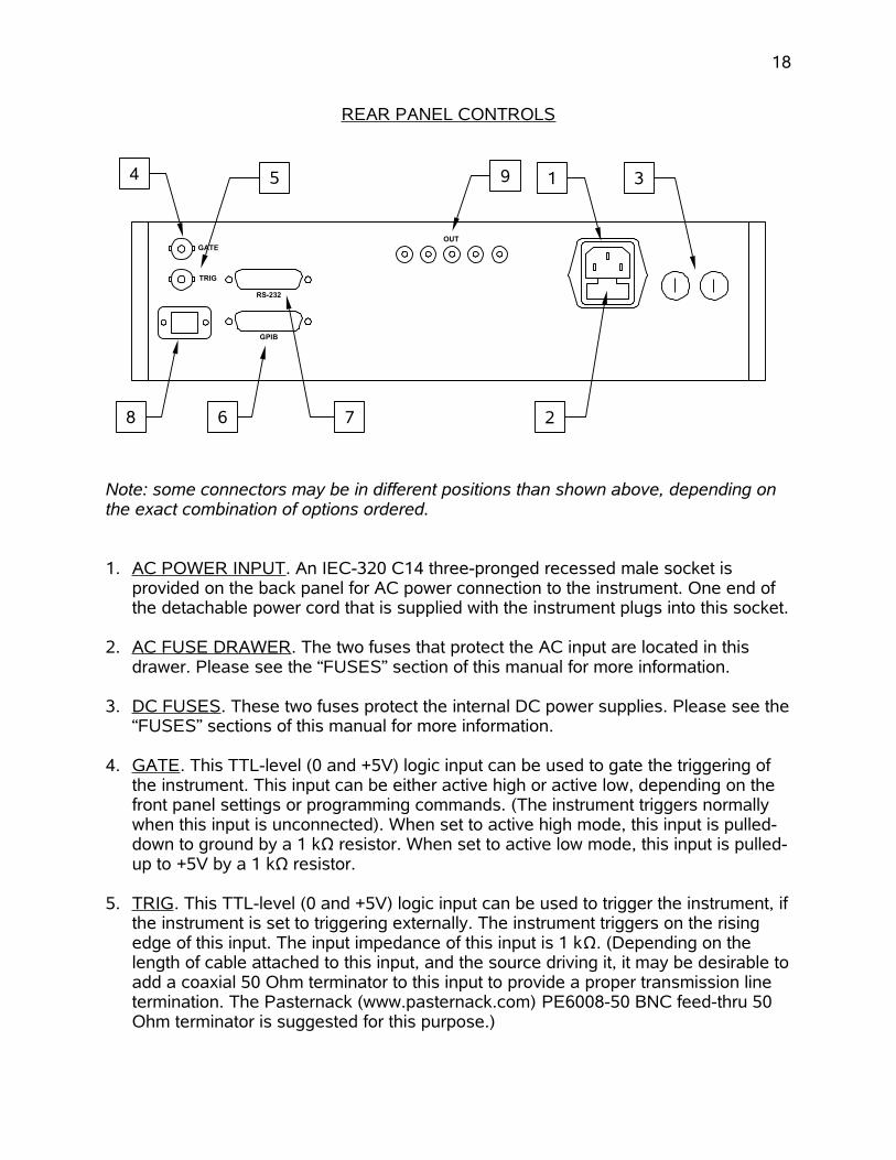
REAR PANEL CONTROLS
Note: some connectors may be in different positions than shown above, depending on the exact combination of options ordered.
1. AC POWER INPUT . An IEC-320 C14 three-pronged recessed male socket is provided on the back panel for AC power connection to the instrument. One end of the detachable power cord that is supplied with the instrument plugs into this socket.
2. AC FUSE DRAWER . The two fuses that protect the AC input are located in this drawer. Please see the “FUSES” section of this manual for more information.
3. DC FUSES . These two fuses protect the internal DC power supplies. Please see the“FUSES” sections of this manual for more information.
4. GATE . This TTL-level (0 and +5V) logic input can be used to gate the triggering of the instrument. This input can be either active high or active low, depending on the front panel settings or programming commands. (The instrument triggers normally when this input is unconnected). When set to active high mode, this input is pulled-down to ground by a 1 kΩ resistor. When set to active low mode, this input is pulled-up to +5V by a 1 kΩ resistor.
5. TRIG . This TTL-level (0 and +5V) logic input can be used to trigger the instrument, ifthe instrument is set to triggering externally. The instrument triggers on the rising edge of this input. The input impedance of this input is 1 kΩ. (Depending on the length of cable attached to this input, and the source driving it, it may be desirable toadd a coaxial 50 Ohm terminator to this input to provide a proper transmission line termination. The Pasternack (www.pasternack.com) PE6008-50 BNC feed-thru 50 Ohm terminator is suggested for this purpose.)
18
GATE
RS-232
GPIB
TRIG
OUT
14 5
2
3
8 7
9
6

When triggering externally, the instrument can be set such that the output pulse width tracks the pulse width on this input, or the output pulse width can be set independently.
6. GPIB Connector . A standard GPIB cable can be attached to this connector to allow the instrument to be computer-controlled. See the “Programming Manual for -B Instruments” for more details on GPIB control.
7. RS-232 Connector. A standard serial cable with a 25-pin male connector can be attached to this connector to allow the instrument to be computer-controlled. A user name (“admin”) and a password (“default”, as shipped from the factory) are required when logging into a serial terminal session. The internal controller attempts to auto-sense the parity setting. It may be necessary to send a few return characters before attempting a login in order to provide enough data to allow this auto-sensing to work. (A standard Linux “agetty” process is used to implement serial control internally.) See the “Programming Manual for -B Instruments” for more details on RS-232 control.
8. Network Connector . (Optional feature. Active on -VXI units only.) This Ethernet connector allows the instrument to be remotely controlled using the VXI-11.3, ssh (secure shell), telnet, and http (web) protocols. See the “Programming Manual for -B Instruments” for more details.
9. OUT CONNECTORS . These ten SMA connectors provide the main output signals. Forbest results, each output should be terminated with a 50Ω load (or, equivalently, all fiveoutputs may be connected to a common 5Ω load). These ten connectors are all wired to the same point internally.
Caution: Voltages as high as ±1000V may be present on the center conductor of these output connectors. Avoid touching this conductor. Connect to these connectors using standard coaxial cables, to ensure that the center conductor is not exposed.
19

GENERAL INFORMATION
BASIC PULSE CONTROL
This instrument can be triggered by its own internal clock or by an external TTL trigger signal. In either case, two output channels respond to the trigger: OUT and SYNC. The OUT channel is the signal that is applied to the load. Its amplitude and pulse width are variable. The SYNC pulse is a fixed-width TTL-level reference pulse used to trigger oscilloscopes or other measurement systems. When the delay is set to a positive value the SYNC pulse precedes the OUT pulse. When the delay is set to a negative value theSYNC pulse follows the OUT pulse.
These pulses are illustrated below, assuming internal triggering and a positive delay:
Figure A
If the delay is negative, the order of the SYNC and OUT pulses is reversed:
Figure B
The next figure illustrates the relationship between the signal when an external TTL-level trigger is used:
20
SYNC OUT(generated by theinternal oscillator)
100 ns, FIXED
MAIN OUTPUT
PULSE WIDTHDELAY > 0
AMPLITUDE,VARIABLE
3V, FIXED
SYNC OUT(generated by theinternal oscillator)
100 ns, FIXED
MAIN OUTPUT
PULSE WIDTH
DELAY < 0
AMPLITUDE,VARIABLE
3V, FIXED

Figure C
As before, if the delay is negative, the order of the SYNC and OUT pulses is reversed.
The last figure illustrates the relationship between the signal when an external TTL-leveltrigger is used in the PWIN=PWOUT mode. In this case, the output pulse width equals the external trigger’s pulse width (approximately), and the delay circuit is bypassed:
Figure D
The delay, pulse width, and frequency (when in the internal mode), of the OUT pulse can be varied with front panel controls or via the GPIB or RS-232 computer interfaces.
21
SYNC OUT
100 ns, FIXED
MAIN OUTPUT
PULSE WIDTHDELAY > 0
AMPLITUDE,VARIABLE
3V, FIXED
> 50 ns
TTL LEVELS (0V and 3V-5V)
TRIG(external input)
PROPAGATION DELAY (FIXED)
MAIN OUTPUT
PWOUT ≈ PWIN
AMPLITUDE,VARIABLE
TTL LEVELS (0V and 3V-5V)
TRIG(external input)
PROPAGATION DELAY (FIXED)
PWIN
TRIGGER MODES
This instrument has four trigger modes:
Internal Trigger: the instrument controls the trigger frequency, and generates the clock internally.
External Trigger: the instrument is triggered by an external TTL-level clock on the back-panel TRIG connector.
Manual Trigger: the instrument is triggered by the front-panel “SINGLE PULSE” pushbutton.
Hold Trigger: the instrument is set to not trigger at all.
These modes can be selected using the front panel trigger menu, or by using the appropriate programming commands. (See the “Programming Manual for -B Instruments” for more details.)
PULSE WIDTH MODES
This instrument has two pulse width modes:
Normal: the instrument controls the output pulse width.
PWIN=PWOUT: the output pulse width equals the pulse width of the trigger signal on the “TRIG” connector. The instrument must be in the external trigger mode.
These modes can be selected using the front panel pulse width menu, or by using the appropriate programming commands. (See the “Programming Manual for -B Instruments” for more details.)
GATING MODES
Triggering can be suppressed by a TTL-level signal on the rear-panel GATE connector. The instrument can be set to stop triggering when this input high or low, using the front-panel gate menu or the appropriate programming commands. This input can also be set to act synchronously or asynchronously. When set to asynchronous mode, the GATE will disable the output immediately. Output pulses may be truncated. When set tosynchronous mode, the output will complete the full pulse width if the output is high, and then stop triggering. No pulses are truncated in this mode.
22

AMPLITUDE DECAY TIME
When reducing the amplitude, it may take several tens of seconds for the amplitude to fall to the set amplitude as the internal capacitor banks discharge.
THE LOAD AND OUTPUT MODULE
The AVOZ-D6-B has ten identical outputs. These outputs can either be combined to drive a single low-impedance (5 Ohms) load, or can be used separately to drive multiple50 Ohm loads simultaneously.
An output module is optionally available to simplify the connection of a single load to multiple outputs. Up to ten identical 50 Ohm coaxial cables (152 cm / 5 feet) are used toconnect the mainframe to the output module. Not all cables are necessarily used at the same time; see the table below for recommended cabling when using the output module to drive a single load.
Load Impedance(RL)
Number of Cables Used to Connect Mainframe toOutput Module (N)
Effective Z0 of Cabling(Z0 = 50 / N)
5.0 Ohms 10 5.0 Ohms7.0 Ohms 7 7.1 Ohms10 Ohms 5 10.0 Ohms
11 to 14 Ohms 4 12.5 Ohms14 to 20 Ohms 3 16.7 Ohms20 to 35 Ohms 2 25.0 Ohms35 to Ohms 1 50.0 Ohms
For instance, to drive a single 5 Ohm load, the following configuration should be used:
The output module is not needed if each output is driving its own load, as shown below:
23
OUTCONNECTORS
(10)
SYNCOUTPUT
ACPOWER
TRIGINPUT
AVOZ-D6-BMAINFRAME
5 Ω,100 W
IN(10)
AVOZ-D6-OM10
Ten coaxial cables
REAL-TIMEOSCILLOSCOPE
CHANNEL A
SCOPEPROBE
OUT(1)
GND (SHIELD)

PREVENTING OUTPUT STAGE FAILURE
The output stage is protected against overload conditions by an overload circuit and fuses on the main frame back panel. However, the output switching elements may fail if the unit is triggered at a PRF exceeding 500 Hz or at duty cycles resulting in an average output power in excess of 100 Watts. Heating and subsequent possible failure of the output stage is reduced if the following action is taken where possible:
PRF is kept to a minimum, i.e. operate in a low PRF range when possible rather than in a high PRF range.
Keep the output PW to a minimum.
Never apply an externally generated voltage to the output port.
24
OUT CONNECTOR #1
SYNCOUTPUT
ACPOWER
TRIGINPUT
AVOZ-D6-BMAINFRAME
50 Ω,10 W
REAL-TIMEOSCILLOSCOPE
CHANNEL A
SCOPEPROBE
OUT CONNECTOR #2
OUT CONNECTOR #10
50 Ω,10 W
CHANNEL BTo 8 other
50 Ohm loads.

OPERATIONAL CHECK
This section describes a sequence to confirm the basic operation of the instrument. It should be performed after receiving the instrument. It is a useful learning exercise as well.
Before proceeding with this procedure, finish read this instruction manual thoroughly. Then read the “Local Control” section of the “Programming Manual for -B Instruments” thoroughly. The “Local Control” section describes the front panel controls used in this operational check - in particular, the MOVE, CHANGE, and ADJUST controls.
1. Connect a cable from the SYNC OUT connector to the TRIG input of an oscilloscope.
2. Connect a 50 Ohm load to each of the ten outputs, using coaxial cabling. Connect one or more oscilloscope probes to the loads of your choice (all ten loads should show the same waveform).
3. Set the oscilloscope to trigger externally with the vertical setting at 100 Volts/div and the horizontal setting at 2 us/div.
4. Turn on the AVOZ-D6-B. The main menu will appear on the LCD.
5. To set the AVOZ-D6-B to trigger from the internal clock at a PRF of 10 Hz:
a) The arrow pointer should be pointing at the frequency menu item. If it is not, press the MOVE button until it is.
b) Press the CHANGE button. The frequency submenu will appear. Rotate the ADJUST knob until the frequency is set at 10 Hz.
25
OUT CONNECTOR #1
SYNCOUTPUT
ACPOWER
TRIGINPUT
AVOZ-D6-BMAINFRAME
50 Ω,10 W
REAL-TIMEOSCILLOSCOPE
CHANNEL A
SCOPEPROBE
OUT CONNECTOR #2
OUT CONNECTOR #10
50 Ω,10 W
CHANNEL BTo 8 other
50 Ohm loads.

c) The arrow pointer should be pointing at the “Internal” choice. If it is not, press MOVE until it is.
d) Press CHANGE to return to the main menu.
6. To set the delay to 1 us:
a) Press the MOVE button until the arrow pointer is pointing at the delay menu item.
b) Press the CHANGE button. The delay submenu will appear. Rotate the ADJUST knob until the delay is set at 1 us.
c) The arrow pointer should be pointing at the “Normal” choice. If it is not, press MOVE until it is.
d) Press CHANGE to return to the main menu.
7. To set the pulse width to 5 us:
a) Press the MOVE button until the arrow pointer is pointing at the pulse width menu item.
b) Press the CHANGE button. The pulse width submenu will appear. Rotate the ADJUST knob until the pulse width is set at 5 us.
c) The arrow pointer should be pointing at the “Normal” choice. If it is not, press MOVE until it is.
d) Press CHANGE to return to the main menu.
8. At this point, nothing should appear on the oscilloscope.
9. To enable the output:
a) Press the MOVE button until the arrow pointer is pointing at the output menu item.
b) Press the CHANGE button. The output submenu will appear.
c) Press MOVE until the arrow pointer is pointing at the “ON” choice.
d) Press CHANGE to return to the main menu.
10.To change the output amplitude:
26

a) Press the MOVE button until the arrow pointer is pointing at the amplitude menu item.
b) Press the CHANGE button. The amplitude submenu will appear. Rotate the ADJUST knob until the amplitude is set at +500V (or -500V for "-N" instruments).
c) Observe the oscilloscope. You should see 5 us wide, 500V pulses.
d) Rotate the ADJUST knob. The amplitude as seen on the oscilloscope should vary.
e) Press CHANGE to return to the main menu.
11.Repeat step 10, but set the amplitude to zero.
12.This completes the operational check.
27

PROGRAMMING YOUR PULSE GENERATOR
KEY PROGRAMMING COMMANDS
The “Programming Manual for -B Instruments” describes in detail how to connect the pulse generator to your computer, and the programming commands themselves. A large number of commands are available; however, normally you will only need a few ofthese. Here is a basic sample sequence of commands that might be sent to the instrument after power-up:
*rst (resets the instrument)trigger:source internal (selects internal triggering)frequency 1000 Hz (sets the frequency to 1000 Hz)pulse:width 1 us (sets the pulse width to 1 us)pulse:delay 2 us (sets the delay to 2 us)volt 200 (sets the amplitude to 200 V)output on (turns on the output)
For triggering a single event, this sequence would be more appropriate:
*rst (resets the instrument)trigger:source hold (turns off all triggering)pulse:width 1 us (sets the pulse width to 1 us)pulse:delay 2 us (sets the delay to 2 us)output on (turns on the output)volt 200 (sets the amplitude to 200 V)trigger:source immediate (generates a single non-repetitive trigger event)trigger:source hold (turns off all triggering)output off (turns off the output)
To set the instrument to trigger from an external TTL signal applied to the rear-panel TRIG connector, use:
*rst (resets the instrument)trigger:source external (selects internal triggering)pulse:width 1 us (sets the pulse width to 1 us)pulse:delay 2 us (sets the delay to 2 us)volt 200 (sets the amplitude to 200 V)output on (turns on the output)
These commands will satisfy 90% of your programming needs.
28

ALL PROGRAMMING COMMANDS
For more advanced programmers, a complete list of the available commands is given below. These commands are described in detail in the “Programming Manual for -B Instruments”. (Note: this manual also includes some commands that are not implemented in this instrument. They can be ignored.)
Keyword Parameter Notes
OUTPut::[STATe] <boolean value>:PROTection
:TRIPped? [query only][SOURce]:
:FREQuency[:CW | FIXed] <numeric value>
[SOURce]::PULSe
:PERiod <numeric value>:WIDTh <numeric value> | EXTernal:DCYCle <numeric value>:HOLD WIDTh | DCYCle:DELay <numeric value>:GATE
:TYPE ASYNC | SYNC:LEVel HIgh | LOw
[SOURce]::VOLTage
[:LEVel][:IMMediate]
[:AMPLitude] <numeric value> | EXTernal:PROTection
:TRIPped? [query only]STATUS:
:OPERation:[EVENt]? [query only, always returns "0"]:CONDition? [query only, always returns "0"]:ENABle <numeric value> [implemented but not useful]
:QUEStionable:[EVENt]? [query only, always returns "0"]:CONDition? [query only, always returns "0"]:ENABle <numeric value> [implemented but not useful]
SYSTem::COMMunicate
:GPIB:ADDRess <numeric value>
:SERial:CONTrol
:RTS ON | IBFull | RFR:[RECeive]
:BAUD 1200 | 2400 | 4800 | 9600 | 19200 | 38400 | 57600 | 115200:ERRor
:[NEXT]? [query only]:COUNT? [query only]
:VERSion? [query only]TRIGger:
29

:SOURce INTernal | EXTernal | MANual | HOLD | IMMediate*CLS [no query form]*ESE <numeric value>*ESR? [query only]*IDN? [query only]*OPC*SAV 0 | 1 | 2 | 3 [no query form]*RCL 0 | 1 | 2 | 3 [no query form]*RST [no query form]*SRE <numeric value>*STB? [query only]*TST? [query only]*WAI [no query form]
30

MECHANICAL INFORMATION
TOP COVER REMOVAL
If necessary, the interior of the instrument may be accessed by removing the four Phillips screws on the top panel. With the four screws removed, the top cover may be slid back (and off).
Always disconnect the power cord and allow the instrument to sit unpowered for 10 minutes before opening the instrument. This will allow any internal stored charge to discharge.
There are no user-adjustable internal circuits. For repairs other than fuse replacement, please contact Avtech ([email protected]) to arrange for the instrument to be returned to the factory for repair. Service is to be performed solely by qualified service personnel.
Caution: High voltages are present inside the instrument during normal operation. Do not operate the instrument with the cover removed.
RACK MOUNTING
A rack mounting kit is available. The -R5 rack mount kit may be installed after first removing the one Phillips screw on the side panel adjacent to the front handle.
ELECTROMAGNETIC INTERFERENCE
To prevent electromagnetic interference with other equipment, all used outputs should be connected to shielded loads using shielded coaxial cables. Unused outputs should be terminated with shielded coaxial terminators or with shielded coaxial dust caps, to prevent unintentional electromagnetic radiation. All cords and cables should be less than 3m in length.
31

MAINTENANCE
REGULAR MAINTENANCE
This instrument does not require any regular maintenance.
On occasion, one or more of the four rear-panel fuses may require replacement. All fuses can be accessed from the rear panel. See the “FUSES” section for details.
CLEANING
If desired, the interior of the instrument may be cleaned using compressed air to dislodge any accumulated dust. (See the “TOP COVER REMOVAL” section for instructions on accessing the interior.) No other cleaning is recommended.
32
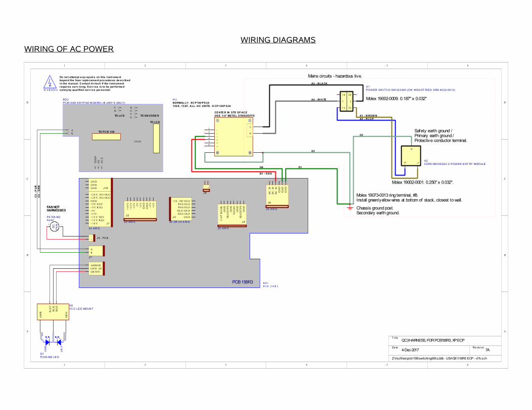
WIRING DIAGRAMSWIRING OF AC POWER
1 2 3 4 5 6
A
B
C
D
654321
D
C
B
A
T i tle
Re vis i onDa te4-Dec-2017
Z:\mjcfiles\pcb\158\switching60hz.ddb - USAGE\158R3 ECP - v7A.sch
QC3 HARNESS, FOR PCB158R3, XP ECP
7A
-3
-2
-1
+4
+5
+6
L
N
GG
US E 1/4" META L STAN DOFFS
PS1
+10 V+15 V REG+15 V NSY-15V-5V+5V R EG+5V N SYGN D+24 V, NO OLO+24 V, NO OLO
+1
0V
+1
5V
-15
V-5
V+
5V
GN
DG
ND
+5
V+
5V
+24 , NO OLOPO S O LOPO S O LO
20 AW G
24 AW G
NE G OLOGND
OLO GN D
20 OR 2 4 A W GC
AP
BA
NK
GN
DH
I-E
XT
PS
NE
GIN
GN
D
GN
D
GR EENGN DAMB ER
DC
IN
DC
IN
DC
IN
GN
DG
ND
GN
D
20 AW G
PCB 158R3
HI-
EX
TP
SG
ND
KA
- +
J1
J2J3
J4
J5
J6
J7
J8
-+
J9 - FA N
J10
GN DGN DGN D
20 AW G
BD1PC B 158R 3
OV
TE
MP
AU
X
AK
YB
ROYG
TO LC D
TO PC B 108
TO EN CODE RTO LC D
104 D
BD 2PC B1 04D K EYP AD B OA RD (-B UN IT S ON LY)
Chassis ground post.
G1
G2
B1 - R ED
G4
G3
LN
G
X2CORC OM 6 EGG1-2 POW ER E NT RY MOD ULE
1
1b
1a
2
2b
2a
X1POW ER SW ITC H SW 32 5-N D (CW IN DUST RIES GRS -40 22-0013)
A1 - B ROW NA2 - B LU E
A3 - B LA CK
A4 - W HITE
GR
N
AM
B
D1P3 95-ND LE D
GR
N
AM
B
BL
KR
ED
WH
T X5VC C LE D MOUN T
DC
FA
N+ -
FA N1P9 768-ND
FAN NOT
C3
- P
UR
C4
- G
RN
Molex 19073-0013 ring terminal, #8.
Molex 19002-0001. 0.250" x 0.032".
Protective conductor terminal.
Molex 19002-0009. 0.187" x 0.032"
Primary earth ground /Safety earth ground /
Secondary earth ground.
Install green/yellow wires at bottom of stack, closest to wall.
Mains circuits - hazardous live.
W ARNIN G
Do not attempt a ny repairs on this instrume ntbeyond the fuse repla cement procedures de scribedin the manual. C ontact A v tech if the instrumentrequires serv icing. S erv ice is to be performe dsolely by qualified serv ice personnel .
HARNESSED
CE NTE R IN STD SP AC E
NORMALLY: EC P180 PS 24156 E, 15 6F, A LL -HC UNITS : E CP1 80P S36

WIRING OF DC POWER
1 2 3 4 5 6
A
B
C
D
654321
D
C
B
A
Re vis i onPri nte d4-Dec-2017
Z:\mjcfiles\circuits\avr-N\avr-n.Ddb - AVR-7B-B-P\univ ps v15.sch
AVR-AHF-1,-3HF,-5B,-7B,-8A, AVO-6HF/-6HZ, AVOZ-D
15C
-
++
-
-
++
-
P
N
P1 N1
BD 2
PC B 1 79 B , TR IMMED
+10 V+15 V REG+15 V NSY-15 V-5V+5V R EG+5V N SYGND+24 V, N O OLO+24 V, N O OLO
+1
0V
+1
5V
-15
V-5
V+
5V
GN
DG
ND
+5
V+
5V
+2 4 , NO O LOPO S O LOPO S O LO
20 AW G
24 AW G
NE G OLOGN D
OL O GN D
20 OR 2 4 A W G
CA
P B
AN
KG
ND
HI-
EX
TP
S
NE
GIN
GN
D
GN
D
DC
IN
DC
IN
DC
IN
GN
DG
ND
GN
D
20 AW G
PC B 1 58 R 3
HI-
EX
TP
SG
ND
- +
J1
J2J3
J4
J6
J8
J10
GNDGNDGND
20 AW G
BD1PC B 1 58 R 3
BLU
GR N
MOUN T W ITH 1/2" S TAN DOFFS
P1 , N1 = 338-243 1-N D, 2 2000uF, 25V x 2R1 ,R 2 (ON BOTTOM): 1 .8K OY
CH S GN D
R6 (CAP BANK CHARGE) = 22 AY, ON TOP. STRAIGHTEN THE LEADS TO MINIMIZE THE HEIGHT.
CHANGES REQUIRED ON PCB 158R3:
K5 (CAP BANK DISCHARGE) = G2RL-14-DC24
C2 (OLO RESPONSE TIME) = 220uF, 16V
PO S O LOOL O GN D
B1 - R ED (TO TPV P OR A AD )

PCB 158R3 - LOW VOLTAGE POWER SUPPLY

PCB 197G - HIGH-VOLTAGE POWER SUPPLY

PCB 183A-S AND 183A-P CAPACITOR BANKS
1 2 3 4 5 6
A
B
C
D
654321
D
C
B
A
RevisionPrinted19-Aug-2005
Z: \mjcfiles\pcb\183\hv-cap-bank.Ddb - pcb183a.sch
PCB183 CAP BANKS
1C
X2
7200K -ND, Mfg . 7200, 4-40 th read standoff 3 /8"
X4
7200K -ND, Mfg . 7200, 4-40 th read standoff 3 /8"
X5
7200K -ND, Mfg . 7200, 4-40 th read standoff 3 /8"
X6
7200K -ND, Mfg . 7200, 4-40 th read standoff 3 /8"
X8
HV WA RN ING
X9
HV WA RN ING
X11
HV WA RN ING
R1 R2 R3
R4 R5 R6
12
J1
HV +
12
J2
HV -
12
J3
GND
12
J4
GND
P1 P2 P3
N1 N2 N3
R7 R8
R9 R10
12
J5
HV +
12
J6
HV -
12
J7
GND
12
J8
GND
P4 P5 P6
N4 N5 N6
X10
7200K -ND, Mfg . 7200, 4-40 th read standoff 3 /8"
X12
7200K -ND, Mfg . 7200, 4-40 th read standoff 3 /8"
X13
7200K -ND, Mfg . 7200, 4-40 th read standoff 3 /8"
X14
7200K -ND, Mfg . 7200, 4-40 th read standoff 3 /8"
X1
HV WA RN ING
X3
HV WA RN ING
X7
HV WA RN ING
183A-S (SERIES CAPACITOR BANK)
183A-P (PARALLEL CAPACITOR BANK)
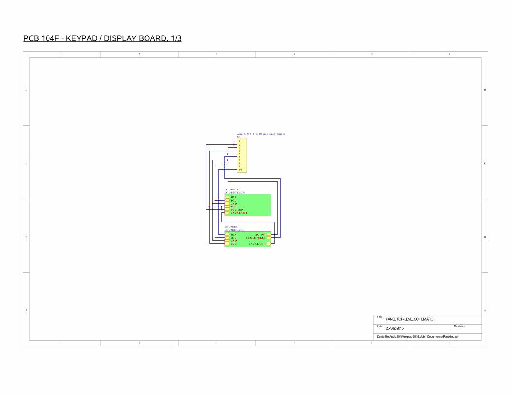
PCB 104F - KEYPAD / DISPLAY BOARD, 1/3
1 2 3 4 5 6
A
B
C
D
654321
D
C
B
A
T i tle
Re vis i onDa te25-Sep-2015
Z:\mjcfiles\pcb\104f\keypad-2015.ddb - Documents\Panelbrd.prj
PANEL TOP-LEVEL SCHEMATIC
12345678910
J5Amp 54999 10-1 , 10 p in s traigh t head er
I2C_INTSC LSD A
GN DVC C
SING LE PUL SE
BA CK LIGH T
EN CODEREN CODER .S CH
I2C_INTSC LSD A
GN DVC C
SING LE PUL SE
BA CK LIGH T
SD ASC LGN DVC CVC C-LEDBA CK LIGH T
LC D-BU TTLC D-BU TT. SCH
SD ASC LGN DVC CVC C-LEDBA CK LIGH T
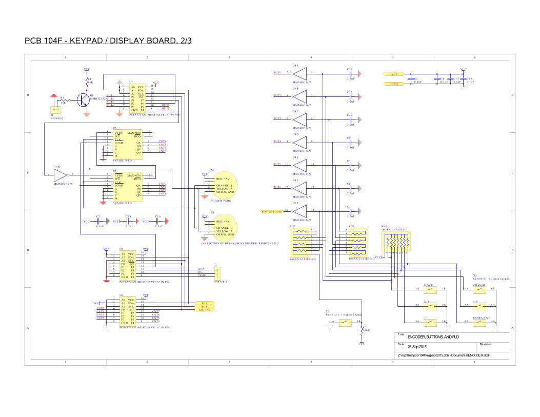
PCB 104F - KEYPAD / DISPLAY BOARD, 2/3
1 2 3 4 5 6
A
B
C
D
654321
D
C
B
A
T i tle
Re vis i onDa te25-Sep-2015
Z:\mjcfiles\pcb\104f\keypad-2015.ddb - Documents\ENCODER.SCH
ENCODER, BUTTONS, AND PLD
VC C
A01
A12
A23
P04
P15
P26
P37
GN D8
P49
P510
P611
P712
INT13
SC L14
SDA15
VC C16
U3
PC F8574 AN (MU ST HA VE "A" IN P/N)
A01
A12
A23
P04
P15
P26
P37
GN D8
P49
P510
P611
P712
INT13
SC L14
SDA15
VC C16
U2
PC F8574 AN (MU ST HA VE "A" IN P/N)
I2C_INTSC LSDA
GND
VC C
VC C
C20. 1uF
C40. 1uF
VC C
VC C
VC C
VC C
C1 50. 1uF
C1 30. 1uF
RED, +5 V12
OR AN GE , B3
YELLOW , A4
GR EEN , GN D5
X6
SO LDER PADS
1A 1BMOV E
2A 2BX1 0
3A 3B+/-
4A 4BEXTRA F INE
5A 5B/10
6A 6BCHAN GE
X582-601-81, 6 b u tton key pad
A01
A12
A23
P04
P15
P26
P37
GND8
P49
P510
P611
P712
INT13
SC L14
SD A15
VC C16
U7
PC F8574 AN (MU ST HA VE "A" IN P/N)
VC C
1A 1B
X282-101-71, 1 b u tton key pad
12
U4 A
MM7 4HC 14N
1110
U1 E
MM7 4HC 14N
SING LE PUL SE
VC C
VC C
C1 0
2.2uF
C1 1
2.2uF
C1 2
2.2uF
C9
2.2uF
C7
2.2uF
C6
2.2uF
C1
2.2uF
34
U4 B
MM7 4HC 14N
56
U4 C
MM7 4HC 14N
98
U4 D
MM7 4HC 14N
1110
U4 E
MM7 4HC 14N
1312
U4 F
MM7 4HC 14N
R1
15K
R415K
2 3 4 5 61 7 8
RN 3460 8X-1-473LF-N D
R2100 K
VC C
23456
1
78
RN2
460 8 X-2-101LF-ND
23456
1
78
RN1
460 8 X-2-101LF-ND
Q1MMBT22 22A
BUT1
BUT2
BUT3
BUT4
BUT5
BUT6
CNT3CNT2CNT1CNT0
CNT4CNT5CNT6CNT7
BUT4BUT3BUT2BUT1
BUT5BUT6
C3
0.1uF
VC C
1 2
J 8640 456-2
123
J7
640 456-3
AU XOVTEMP
CT EN4
D/U5
CL K14
LO AD11
MAX /MIN12
RC O13
A15
QA3
B1
QB2
C10
QC6
D9
QD7
U6
SN74HC 191 D
CT EN4
D/U5
CL K14
LO AD11
MAX /MIN12
RC O13
A15
QA3
B1
QB2
C10
QC6
D9
QD7
U8
SN74HC 191 D
9 8
U1 D
MM74HC 14 N
CNT4CNT5CNT6CNT7
CNT0CNT1CNT2CNT3
VC C
C1 4
0. 1uF
VC C
C1 6
0. 1uF
RED, +5 V12
OR AN GE , B3
YELLOW , A4
GR EEN , GN D5
X4
1x5 SEC TION OF BRE AK AW AY HEA DE R, R EMOV E P IN 2
VC C

PCB 104F - KEYPAD / DISPLAY BOARD, 3/3
1 2 3 4 5 6
A
B
C
D
654321
D
C
B
A
T i tle
Re vis i onDa te25-Sep-2015
Z:\mjcfiles\pcb\104f\keypad-2015.ddb - Documents\LCD-BUTT.SCH
LCD CIRCUITS, MECHANICAL
A01
A12
A23
P04
P15
P26
P37
GND8
P49
P510
P611
P712
INT13
SC L14
SDA15
VC C16
U5
PC F8574 AN (MU ST HA VE "A" IN P/N)
VC C
SDASC L
VC C
VC C
GN D
VC C
VC C
C50.1uF
1 2
U1 A
MM74HC 14 N
13 12
U1 F
MM74HC 14 N
5 6
U1 C
MM74HC 14 N
PA D3LED +
PA D4LED -
X34-40 MOUN T
X14-40 MOUN T
X94-40 MO UN T
X84-40 MO UN T
3 4
U1 B
MM7 4HC 14N
LC
D P
OW
ER
VC C
23456
1
78
16
9101112131415
RN 4
481 6P-2 -10 2LFC T-N D
VC C
VC C
C82.2uF
R3
22
DB 71
DB 62
DB 53
DB 44
DB 35
DB 26
DB 17
DB 08
E19
R/W10
RS11
VEE12
VS S13
VC C14
E215
NC16
LED+17
LED-18
X1 0
A3 2707-09-ND
R6
0
CC
WC
W
W
TO
P V
IEW
12
3
R5
PO T, 326 6X 10K H OR IZ
VC C
BL
TP1TES T-LO OP

MAIN WIRING - POSITIVE (-P) UNITS
1 2 3 4 5 6
A
B
C
D
654321
D
C
B
A
Re vis i onPri nte d4-Dec-2017
Z:\mjcfiles\circuits\avoz\avoz.Ddb - AVOZ-D6-B-P\D6 wiring v3.sch
AVOZ-D6-B-P
3A
HVHV
GN DGN D
197 G
R1 = R2 = R3 =
R4 = R5 =
R6 = R7 =
POS VE RS ION, HA S:
D2 ,4,5,7 NORM ORIEN T.
R2 6, R2 7 = UNU SE DR2 4, R2 5 = R8 =
R1 4,1 8,2 1,2 2 = ZE ROR1 3,1 7,1 9,2 0 = UNUS ED
GN
DO
LO
SS
RE
NV
C
+5
V+
15
V-1
5V
GN
D
+2
4V
UV11C 24-P125 , W ITH P CB 19 7G
GN
D1
GN
D2
SS
R
N/C
GN
D3
+5
VL
V+
N/C
OU
T
TR
IG
HV X
M1PG-P
CO NN 2OU T
P2, R2
P3, R3 N3 ,R 6
P1, R1 N1 ,R 4
N2 ,R 5
G G
+ + - -
G G
++
+-
-- +
++
--
-
BD 1PC B 183A -S
CH S GND
HV1
DANG ER - H IG H VOLTA GES
HV 2
DA NG ER - H IGH VO LTA GES
AV OZ-D 6: TE N ID ENTIC AL 0.141" SR402 (NOT SR 405!)
158 GND
CH S GND
+5V
CH AN GE S RE QU IR ED ON PC B 295 D (P RF LIM)OV
TE
MP
AU
X
AK
BD2PC B104 F K EY PAD
1) INS TALL C 9 = 0.15uF P OLY (500 Hz )
OUTPU T CAB LES AND C ONNS .
+15 V NSY (158P )
AMPL ITU DE , 0 -1 0V1
OF FSET, 0 -1 0V2
PW , 0 -10 V3
SPARE, 0 -1 0 V4
O.PO L5
O.ZO UT/PW R NG6
O.LO GIC7
O.SQ U8
O.TR I9
O.SINE10
O.EA11
O.SPE EDUP-RNG12
AMPL RNG 413
AMPL RNG 314
AMPL RNG 215
AMPL RNG 116
AMPL RNG 017
XR LY 518
XR LY 4 (EO)19
XR LY 3 (V-I)20
XR LY 2 (DU AL PW )21
XR LY 122
GATE23
EXT T RIG24
SYNC O UT25
MAIN OU T26
+5V O N/OF F27
+15 V ON/OFF28
OUT
SYNC
VS PAR EVP RF
GA
TE
+2
4V
GN
D
TR
IG
AU
XG
ND
VF
NO
CNC
SW
NO
C NC
AM
P
LA N
OLIMEX
295 D
BD 3PC B 295D
CONN 3GATE
CONN 4EXT T RIG
CO NN 1SY NC
CONN 5AMP (-EA U NITS ONLY )
+24 V, N O OLO
FOR THE A VOZ-D 6-B, W IRE THE CA P BA NK GND TO THE "X" PIN IN STE AD OF "GND 1", IN ORDE R TO IS OLATE THE LOGIC AND P ULS E GR OUND S.
CH S GND
-15V
+5V
15 OY
OLO GN DPO S O LO
220 OY
P1 -P 3: 2 20uF, 4 00VN1 -N 3: 2 20uF, 4 00V (OP POSITE OF SILK SC REE N +/-)R1 -R 6 (B OT, UND ER CAP S): 150K OY
US E 1/2" S TANDOFFS
+24 V, N O OLO
NOT US EDZE RO
NOT US EDNOT US ED
NOT US ED
4.7K326 6W , 5K
P2, R2
P3, R3 N3 ,R 6
P1, R1 N1 ,R 4
N2 ,R 5
G G
+ + - -
G G
++
+-
-- +
++
--
-
BD4PC B 183A-S
CH S GND
FOR BOTH:

PERFORMANCE CHECK SHEET
42