instructions & maintenance manual is an iso9001:2000 certified company by ul registrar delta...
TRANSCRIPT

Niedner is an ISO9001:2000 certified company by UL registrar
DELTA HYDRO HOSE TESTER
INSTRUCTIONS & MAINTENANCE MANUAL
675 Merrill Street / Coaticook, Quebec, Canada J1A 2S2 Tel: 1-800-567-2703 or (819) 849-2751/ Fax: (819) 849-7539
READ and UNDERSTAND these Instructions PRIOR to operating the DELTA HYDRO HOSE TESTER
Failure to do so may result in BODILY INJURY or HOSE TESTER DAMAGE
RE
VIS
ED
JU
NE
20
09

Table of Contents
INTRODUCTION ........................................................................................................... 1 CAUTIONS ................................................................................................................... 2 Delta Hydro Hose Tester Operating Instructions ...................................................... 3 Hose Tester Maintenance and Care ........................................................................... 4 GENERAL .................................................................................................... 4 INSPECTION ................................................................................................. 4 LUBRICATION ............................................................................................. 4 FILTER CLEANING ..................................................................................... 4 FLUSHING ................................................................................................... 5 DRAINING .................................................................................................... 5 STORAGE ................................................................................................... 5 ANTI-FREEZE ............................................................................................. 5 Hose Tester Trouble Shooting ..................................................................................... 6 HOSE PRESSURIZES SLOWLY NO PRESSURE BUILD UP WATER IN OIL Pressure Washer Operation ....................................................................................... 7 TO USE THE PRESSURE WASHER EQUIPMENT LIQUID INJECTOR Procedures from NFPA 1962 ....................................................................................... 8 DELTA HYDRO HOSE TESTER FEATURES CHART ............................................... 12 DIAGRAMS AND PARTS LIST CDHT1500 ................................................................................................. 13 CDHT2000 – Upright ................................................................................. 15 CDHT2000 – Low Profile ........................................................................... 17 CDHT2000GA ............................................................................................ 19 CDHT3500 .................................................................................................. 21 DELTA HYDRO ACCESSORIES ............................................................................... 23

INTRODUCTION
Niedner’s DELTA HYDRO HOSE TESTER is the only hose tester with both patented stainless steel manifold and automatic safety check valves. The stainless steel material used in the manifold contributes to an extended life by not deteriorating prematurely. Unlike other hose testers that have ball valves requiring hands-on operation during tests, the DELTA HYDRO HOSE TESTER has automatic check valves that create a safety margin for the fire fighter during hose test pressurization. These check valves are fully automatic, allowing the operator to maintain a safe distance while testing hose.
Niedner’s greatest concern is that personnel will be struck by a whipping burst hose line. Creating a safety perimeter will prevent this disaster. The automatic check valves on all DELTA HYDRO HOSE TESTERS enhance this safety zone and minimize the chance of injury.
DELTA HYDRO HOSE TESTERS have the following high quality features:
• Reliable top quality oil bath pump for consistent performance, constant lubrication and long life.
• A powerful industrial motor as a power source on all the electric hose testers, except the HT3500 model that is equipped with a 4.0 HP ODP (open drip proof) motor.
• Stainless steel construction for corrosion-free long life.
• Designed to meet or exceed NFPA guidelines.
• A one year limited warranty.
Hose testers should be used by competent, trained personnel within the prescribed guidelines, as set forth by the manufacturer and NFPA. Failure of a hose tester under pressure may cause serious bodily injury or property damage. For safety reasons, Niedner strongly urges that hoses being tested should be tied together. This will minimize the chance of injury should a hose burst.
Niedner disclaims any and all liability for injury or damage to any and all persons or property that may be caused by the operation of the DELTA HYDRO HOSE TESTER, whether it is a result of misunderstanding of instructions, lack of prudent safety precautions or not following the safety standards of the industry. All questions should be directed to your Niedner Distributor or to Niedner at 1-800-567-2703.
1
CAUTIONS
• 3” (76 mm) and LARGER HOSE – All 3”, 3½”, 4”, 5”, and 6” (76, 89, 102, 127 and 152 mm) hoses are to be tested flat on the ground with the use of a short smaller diameter sized hose between the tester and the hose being tested. The larger diameter hoses should never be attached directly to a hose tester check valve.
• PUMP HEAT BUILDUP – The Hose Tester is equipped with a positive displacement oil bath pump. An oil bath pump normally runs cooler than other types of pumps, but care must still be taken. With the pump operating, the pressure regulator directs water back into the inlet side of the pump, creating a closed loop re-circulating action. This causes heat to build up inside the pump. Caution must be used to prevent the pump temperature from exceeding 160° F (71°C). Once the desired test pressure is reached, the pump should be turned off, allowing the check valves to hold the pressure for the three-minute period specified by NFPA. HEAT DAMAGE WILL VOID THE WARRANTY.
• INLET WATER PRESSURE – Inlet water pressure should not exceed 120 psi (827 kPa), or non-warranty internal damage can occur to the pump.
• TIE HOSES TOGETHER – At every coupling connection, use a hose safety tie-line to tie all the hoses together for stability and safety in case of hose failure.
• GAS ENGINE HOSE TESTER – Full throttle of the gas engine is not required. Setting the throttle at half speed or slightly higher is usually sufficient. Using the sound of the engine as a guide, strive for a smooth, vibration-free operation. Excessive vibration will reduce the life expectancy of the Hose Tester.
• ELECTRICAL EXTENSION CORD – With the electric Hose Tester models, an electrical extension cord should NOT BE USED, unless the extension cord is properly sized for the amperage rating of the electric motor. Use of an improper electrical extension cord may cause non-warranty damage.
• MAXIMUM SAFETY – Carefully follow all instructions in this booklet and in NFPA 1962. Personnel safety is the first priority in all hose testing evolutions.
• WATER – DO NOT RUN THE PUMP WITHOUT WATER
• RETURNS – All liquids are to be REMOVED from the hose tester prior to shipping. Any hose tester shipped with liquids must have MSDS sheets included with the shipment paperwork and Niedner must be advised that the hose tester will be arriving with flammable liquids.
• WARNING: A GFCI (Ground Fault Circuit Interrupter) wall plug is recommended when using electric appliances in close proximity to conductive fluids.
2

Delta Hydro Hose Tester Operating Instructions [Note: Become thoroughly familiar with these Instructions & Maintenance Manual AND
NFPA Standard 1962 before operating the Delta Hydro Hose Tester]
1. Position the Hose Tester on a hard, flat, and stable surface. It must be placed so it is NOT tilted more than 10
degrees off vertical. If the test site has any incline, place the Hose Tester at the lowest part of the incline, with the hose discharge ends at the highest position. This will help all air to be expelled from the hose. NOTE: All hose being tested together must be of the same Service Test Pressure.
2. Check fluid levels: Electric Models, oil in the pump; Gas Models, oil in the pump, plus fuel and oil in the gas engine. Levels should be centered in sight glass or at the appropriate level on the dipstick.
3. Connect hose to TWO or more Hose Tester outlets. Cap off any outlet not being used with OPEN bleed caps, NOT blind caps. The maximum length of hose per outlet should not exceed 300’. WARNING: All 3” and larger diameter hose shall be service-tested while lying flat on the ground. Use a short length (also called pony lines) of smaller diameter sized hose with the same service pressure to connect to the Hose Tester.
4. Install OPEN bleed caps on the hose ends. At every coupling connection, use a hose safety tie-line and tie all the hoses together for stability and safety, in case of hose failure or coupling separation.
5. Connect the Hose Tester to the hydrant water supply. Plug in the [electric] Hose Tester to a grounded 20amp circuit. If an electric extension cord is used, it MUST be properly rated, or non-warranty damage can occur to the Tester.
6. Open both ball valves on the Hose Tester. Begin filling the hose slowly, driving ALL AIR from the hose.
7. After the hose has filled and water is coming out of all bleed caps, close the inlet ball valve. Now water will flow through the pump and into the manifold, making sure that NO air is left in the pump. Allow the water to flow though the pump for several minutes before closing all bleed caps. Once the desired test pressure is reached, close ¼” ball valve of the manifold, the pump should then be turned off to determine whether the pressurized outlet side of the machine and its related components are leak free. Pressure to be held for the three minute period specified by NFPA.
8. Once hose is filled and completely purged or bled of air, the pressure gauge should read from 50 PSI to120 PSI hydrant pressure. If the needle in the gauge has not moved yet, the gauge may be faulty. Stop the hose tester and do not resume until the gauge is replaced.
9. Bleed caps should now be closed. Make sure the pressure regulator is set at minimum pressure (full counter-clockwise) when beginning a hose test. Turn on the hose tester and slowly turn the pressure regulator handle clockwise until the desired test pressure is indicated. DO NOT force handle past its normal stop. If gas model is being used, run gas engine at only 1/3 to ½ throttle. NOTE: This pressurizing step could take 15 to 20 minutes or more, depending on how much hose, of what size, and of what type, is being tested.
WARNING: the hose tester pressure pump should never be run nor started unless there is an adequate supply of water flowing through the pump plumbing and manifold. Damage to equipment, personnel injury, or death may result if the pump is operated without an adequate water supply.
10. Follow the procedures of NFPA 1962, Current Edition, concerning wearing full protective clothing, personnel positioning, slowly charging, holding pressure, and inspecting hose and couplings.
11. After the test is complete, switch off hose tester, turn off the water supply, unplug the Tester, and open the bleed caps to relieve the pressure. Remove the bleed caps from the hose and disconnect the hose from the Hose Tester.
WARNING: The hose tester pressure pump must always be turned off before the water supply. Shutting off the water supply while the hose tester pressure pump is still in operation may result in equipment damage or serious personal injury.
12. After each use, blow low pressure compressed air through the pump and manifold of the Hose Tester. Close the inlet ball valve when doing this step so that the air can circulate through the pump and into the manifold. NEVER leave water in the Hose Tester!!!! Refer to page 5 for storage of the hose tester in the Instructions and Maintenance Manual.
3

Hose Tester Maintenance and Care
GENERAL: Check oil levels in pump and gas engine before each use. Always flush the Hose Tester and the Pressure Washer equipment with fresh water after each use, especially if salt water or brackish water has been used for hose testing. Brass check valve assemblies, not aluminum, are recommended for salt water and brackish water areas, and can be specially ordered.
INSPECTION: Before each use, as recommended by NFPA 1962, the Hose Tester should be visually inspected, to identify any damaged components, or other potential problems or dangers.
Periodically, examine each check valve assembly for corrosion, foreign matter, and O-ring condition. To examine the check valves, carefully use a screwdriver and your fingers to pull out the center disc of each check valve. If any O-ring is cracked, damaged, or missing, order replacements from an Authorized Niedner Distributor. O-ring Part Number is DEL-1006.
LUBRICATION: A new Hose Tester has a break-in period of 50 hours of operation. The pump oil should be changed after this period. Use a 10W-30 or 5W-30 synthetic oil. Thereafter, the pump oil change should be performed after every 3-5 months or 200 hours of operation. The proper oil level for all models is in the middle of the “sight glass”, or at the cut notch on the dipstick. IMPROPER PUMP LUBRICATION WILL VOID THE WARRANTY. For lubrication of the gasoline engine, refer to the gasoline engine manufacturer’s manual. [Normally, these gas engines use regular 10W-30 motor oil.]
FILTER CLEANING: The Hose Tester is equipped with an In-Line Water Strainer for efficient operation. This is Part Number DEL-1181. See Diagram and Parts List for its location on your Tester. To clean this filter, unscrew the filter casing and remove the strainer inside. Flush thoroughly with water, or replace the unit entirely if it is damaged or corroded.
4

DRAINING THE HOSE TESTER AFTER A SERVICE TEST
FLUSHING: Always flush the Hose Tester and Pressure Washer Equipment thoroughly with fresh water. Remove all bleed caps and store separately.
DRAINING: To drain the Hose Tester, carefully use a small screwdriver and your fingers to pull out the center disc of one of the bottom outlet check valves. Carefully insert the screwdriver behind the center disc to keep the check valve open. Then, gradually tilt the Hose Tester forward, until all water has drained. [Do not allow oil to leak from the dipstick when tilting Hose Tester.]
SHORT TERM STORAGE (3 months): Blow low pressure compressed air through the pump and manifold. To do this, close the inlet ball valve. To assist with this step, a Storage Adapter, Part Number DEL-1040, is available. It attaches to a male GHT, so a 1 ½” (38 mm) or 2 ½” (64 mm) Male x GHT Male adapter is also needed. This attaches to the inlet swivel.
LONGER TERM STORAGE: Drain all the water out of the hose tester with the use of a “storage adapter”, then low pressure air is to be blown through the system until no more water comes out. Hose tester is then to be filled with anti-freeze by following the instructions below.
ANTI-FREEZE: When storing the Hose Tester for an extended period in cold climates, it is recommended that a 50/50 solution of water and ethylene glycol anti-freeze be used to fill the pump waterway. Follow these steps:
• Close the inlet ball valve.
• Cap off all the check valves except for the top one on the 1500 models or one of the upper two on the 2000 & 3500 models. In the un-capped check valve, carefully insert a small screwdriver as described in DRAINING above, for venting purposes.
• Unscrew the In-Line Water Strainer.
• Attach a 3 foot (0.9 m) piece of garden hose with a female GHT to the In-Line Water Strainer connection.
• With a funnel in the garden hose, slowly pour in the mixture of water and ethylene glycol (50% water and 50% ethylene glycol) until it seeps out of the top check valve.
• When the antifreeze solution seeps through the check valve, remove the small screwdriver and cap off that check valve.
• Remove the funnel and clamp the open end of the garden hose, so that it will not leak
5

Hose Tester Trouble Shooting
HOSE PRESSURIZES SLOWLY – Hose lines pressurizing slowly is normal, and could take 15 to 20
minutes or more, depending on hose size, quantity, and construction. This is because the Hose Tester pump is significantly smaller than that of a fire pumper, and pressurizing is pumping more water into the hose until the desired test pressure is attained. However, when using a Hose Tester and the NFPA guidelines are being followed, the fire pumper pump is not in jeopardy, nor is the fire pumper placed out of service for testing hose.
NO PRESSURE BUILD-UP – Check that the following pressurizing settings are all correct: • Inlet ball valve is CLOSED.
• Water supply is ON.
• Water supply DOES have pressure.
• ¼” (6.3 mm) ball valve is OPEN.
• Hose has NO LEAKS.
• NO AIR remains in system.
Follow these 10 steps to check the operation of the Delta Hydro Hose Tester
• Open the ¼” (6.3 mm) ball valve; this valve is always open unless the pressure washing equipment is being used.
• With pump in OFF position, disconnect all hose from the Hose Tester.
• Install OPEN bleed caps (not blind caps) on all hose tester outlets.
• Open the inlet ball valve and also the ¼” manifold ball valve.
• Set the pressure regulator control to minimum pressure (FULL counter-clockwise). • Connect supply hose, start hydrant flow, and bleed manifold of ALL air.
• When a solid stream of water flows from each bleed cap, close the inlet ball valve.
• Water is now flowing through the pump. Wait briefly and then close all bleed caps.
• The pressure gauge should now indicate hydrant pressure; if not, check gauge by following the guidelines below**.DO NOT CONTINUE if the gauge may be faulty.
• Start pump operation (gas or electric) and slowly increase pressure by turning the Pressure Regulator control clockwise. Do not force the control past its normal stop.
• Pressure should gradually increase to 400 – 500 PSI range. This is maximum pressure!
If the above steps have produced 400 – 500 PSI gauge readings, the tester is working normally; if not, check or note the following:
� Is there any water leakage whatsoever at any of the couplings, hose or anywhere else?
� Is the incoming pressure of the hydrant flow in the 20 – 120 PSI range? Water must flow.
� Is the 2” ball valve totally closed during pressurizing with the ¼” ball valve open?
� Is the In-line strainer free of obstructions? See Manual for parts list diagram location. ** Test the pressure gauge by installing a pressure line gauge (known to be operative) between a bleeder cap and a discharge. Then repeat steps above noting readings on both gauges.
One additional step can be taken by a trained mechanic – check the poppet valves in the pump. Remove the three top and three side nuts from the brass head of the pump. Carefully remove the poppet valves with needle nose pliers. Check poppet valve operation by pushing the spring mechanism inside the casing using the tip of the pliers or a pen. Re-assemble by reversing these steps.
WATER IN OIL: If the pump oil is milky in appearance, the cause could be that worn packing rings are leaking. This can be a result of normal Hose Tester usage. Leaking packing rings should be replaced. Packing Ring Replacement Kits are available from Niedner Distributors. Specify hose tester model and serial number when ordering.
If you are still having problems with your Hose Tester, please contact Niedner at 1-800-567-2703
6

Pressure Washer Operation
All DELTA HYDRO HOSE TESTERS can be used with the optional pressure washer attachment. The pressure washer will clean dirt from equipment without peeling decals. The pressure washer attachment also acts as a good hose-cleaning device. The pressure washer will remove dirt from the hose without damaging the fabric of the jacket. Pressure washers are rated by PSI; the greater the PSI, the lower the water flow. A higher PSI will generate a lot of air with the water.
DELTA HYDRO HOSE TESTERS are equipped with a dedicated outlet for pressure cleaning. The water supply must be a pressure supply line as the pump will not self-prime nor will it operate on gravity fed lines.
* * * DO NOT RUN THE HOSE TESTER PUMP WITHOUT WATER * * *
TO USE THE PRESSURE WASHER EQUIPMENT:
1) Close the inlet ball valve AND the ¼” (6.3 mm) ball valve located on the inside of the manifold. This ¼” (6.3 mm) ball valve closes off the manifold from the pump. When using the pressure washer equipment with Low Profile Models 1500 and 2000, if a pressure reading is desired, install a line gauge on the pressure washer hose.
2) Connect the pressure washer to the pump using the dedicated outlet.
3) Connect the water source to the Hose Tester inlet ball valve. Turn on the incoming water.
4) Start the pump then adjust the pressure by turning the black handle on the pressure regulator clockwise.
5) Water up to 140° F (60°C) may be used, however, extreme caution must be exercised to avoid heat damage. With pump on, do not keep the pressure washer in closed/off position for more than one minute when using hot water.
6) If it becomes necessary to shut off the motor during operation, relieve the high pressure prior to attempting to restart – see next step.
7) The electric motors WILL NOT START against high pressure. The pressure may be relieved by momentarily opening the ¼” (6.3 mm) ball valve into the manifold or by squeezing the trigger on the pressure washer.
LIQUID INJECTOR:
The liquid injectors used with the DELTA HYDRO HOSE TESTER pressure washers are LOW PRESSURE injectors. The pressure must be reduced before the injector will operate. This is accomplished by (looking at tip from trigger) turning the spray gun nozzle COUNTER-CLOCKWISE (to the left) to inject liquid and CLOCKWISE (to the right) to stop the injection. The principal of the liquid injector is to soap down the project, then turn the nozzle back to high pressure for wash down. When first used, the nozzle may need to be cycled back and forth from high pressure to low pressure several times.
* * * THOROUGHLY RINSE ALL PRESSURE WASHER PARTS AFTER USE * * *
7

The following procedures have been extracted from NFPA 1962 (2008 edition) [With Niedner notes in brackets and italics]
7.2 Service Test Procedure.
7.2.1 Each length of hose to be service-tested shall be inspected as specified in Section 4.6.
4.6 Hose Inspection.
4.6.1 Physical inspection shall determine that the hose, couplings, and any nozzle have not been vandalized, are free of debris, and exhibit no evidence of mildew, rot, or damage by chemicals, burns, cuts, abrasion, and vermin.
4.6.2 During the inspection, a check shall be made to determine if the service test of the hose is current.
4.6.3 Liner Inspection.
4.6.3.1 The interior of the hose at each end shall be visually inspected for any physical signs of liner delamination.
4.6.3.2 If the liner shows signs of delamination, the hose shall be condemned.
4.6.4 If the hose fails the physical inspection, it shall be removed from service and either repaired as necessary and service-tested as specified in Chapter 7 or condemned.
4.6.5 The couplings shall be inspected as specified in 6.2.3 and 6.2.4.
6.2.3 After each use, and during each hose service test, couplings shall be visually inspected for the following defects: (1) Damaged threads (2) Corrosion (3) Slippage on the hose (4) Out-of-round (5) Connections not rotating freely (6) Missing lugs (7) Loose external collar (8) Internal gasket defects (9) Other defects that impair operation
6.2.4 Hose with defective couplings shall be removed from service and the couplings repaired or replaced.
7.2.2 Any length of hose that fails the inspection shall be removed from the service test area and repaired as necessary or condemned.
7.2.3 Lengths of hose to be tested simultaneously shall be of the same service test pressure and collectively, shall be considered the hose test layout.
7.2.4 The total length of any hose line in the hose test layout to be service-tested shall not exceed 300 ft (91 m).
7.2.5 The hose test layout shall be straight, without kinks or twists.
7.2.6 All 3 ½” (89 mm) and larger diameter hose shall be service-tested while lying flat with a short length of smaller diameter hose with the same or higher proof pressure used to connect the pressure source to the hose being tested. [Niedner does not recommend testing large diameter hose on the 1500 series Testers].
7.2.7 A test location shall be selected that allows connection of the hose testing apparatus (pressure source) to a water source.
7.2.8 A hose testing machine, a stationary pump, or a pump on a fire department apparatus shall be used as a pressure source.
7.2.8.1 If a hose testing machine is used, the procedure defined in Section 7.6 shall be used.
7.2.8.2 If a stationary pump or a pump on a fire department apparatus is used, the procedure defined in Section 7.7 shall be used [see page 11 of NFPA 1962 – 2008 edition).
8

7.2.9 At the conclusion of the test, the hose records shall be updated to indicate the results of the service test for each length of hose tested.
7.2.10 Any hose that fails the inspection defined in 4.6 [specified on previous page], bursts or leaks during the service test, or has couplings that leak or are otherwise found defective as defined in 6.2.3 [specified on previous page] shall be tagged as required in 5.1.6 or 5.3.6 and removed from service.
5.1.6 and 5.3.6 Hose removed from service for repair or because it has been condemned shall be tagged with a distinctive tag with the reason for removal from service noted on the tag.
7.2.10.1If the hose leaks or the hose jacket fails inspection, a distinguishing mark noting the location of the defect(s) shall be placed on the hose.
7.2.10.2 If the couplings fail or are defective, they shall be repaired or replaced.
7.2.10.3 If the hose cannot be repaired, the couplings shall be removed from both ends.
7.2.11 If the hose is repaired, or the couplings are repaired or replaced, the hose shall be service tested in accordance with Chapter 7 before being placed back in service 7.2.12 After testing, all hose shall be thoroughly cleaned, drained, and dried as specified in Section 4.7 before being placed in service or storage.
4.7 Cleaning and Drying. 4.7.1 After each use, all hose shall be cleaned.
4.7.2 If dirt cannot be thoroughly brushed from the hose or if the hose has come in contact with harmful materials, the hose shall be washed.
4.7.3 If, during use, the hose has been exposed to hazardous materials, it shall be decontaminated by the method approved for the contaminate.
4.7.4 Covered hose shall be permitted to be wiped dry.
4.7.5 Hose shall not be dried on hot pavements or under intense sunlight.
7.3 Unlined Hose. Unlined fire hose shall be replaced with an approved lined fire hose when service testing is required.
7.4 Booster Hose.
7.4.1 Booster hose shall be tested in accordance with Section 7.2 to 100 percent of its maximum working pressure.
7.4.2 If a maximum working pressure cannot be determined for the hose, it shall be tested to 110 percent of the normal highest working pressure as used in the system.
7.5 Suction Hose
7.5.1 Suction hose shall be dry-vacuum tested using the following procedure: (A) The hose shall be attached to a suction source. (B) The free end shall be sealed with a transparent disk and connected to an accurate vacuum
measuring instrument. (C) A 22” mercury (0.75-bar or 74.5-kPa) vacuum shall be developed. (D) While holding the vacuum for 10 minutes, the interior of the hose shall be inspected through
the transparent disk. (E) There shall be no signs of physical damage or collapse of the lining into the waterway.
7.6 Service Test using a Hose Testing Machine. The procedure defined in this section shall be used
when hose is service tested using a hose testing machine. [Warning: Because there is potential for catastrophic failure during testing of fire hose, it is vital that safety precautions
always be taken. Do not deviate from the procedures prescribed in Section 7.6]
9
7.6.1 Testing Machine Integrity. The condition of the hose testing machine shall be thoroughly checked daily before each testing session and before the machine is used after being transported to a new testing site.
7.6.1.1 The hose testing machine shall be carefully examined for damaged components that might fail during the test.
7.6.1.2 If any damage is discovered, the hose testing machine shall not be used until the damaged component(s) is repaired or replaced.
7.6.1.3 A pressure leak integrity test shall be performed on the machine to determine whether the pressurized outlet side of the machine and its related components are leak-free.
7.6.1.3.1 The fire hose outlet connection(s) of the machine shall be capped or otherwise closed.
7.6.1.3.2 Pressure shall be applied through the machine using the integral pump to a level that is 10 percent higher than the highest service test pressure needed for the hose to be tested.
7.6.1.3.3 The pressure shall be held for 3 minutes with the pump turned off.
7.6.1.3.4 If leaks are detected, the testing machine shall not be used until the leaking component(s) is repaired or replaced.
7.6.1.4 The test gauge that is used to read the test pressure shall have been calibrated within the previous twelve months.
7.6.2 Conducting the test
7.6.2.1 The test layout shall be connected to the outlet side of the water supply valve [check valve] on the hose testing machine.
7.6.2.2 A test cap with a bleeder valve shall be attached to the far end of each hose line in the test layout. If a test cap is not available, a nozzle with a non-twist shutoff shall be permitted to be used.
7.6.2.3 With the test cap valve or the nozzle open, the pressure shall be raised gradually to 45 psi +/- 5 psi (310 kPa +/- 35 kPa).
7.6.2.4 After the hose test layout is full of water, all the air in each hose line shall be exhausted by raising the discharge end of each hose line above the highest point in the system.
[Niedner Warning: Take care to remove all air from the hose before the test cap valve or the nozzle is
closed and the pressure raised. If air remains in the system, a serious accident could occur]
7.6.2.5 Each nozzle or test cap valve shall be closed slowly, and then the outlet water supply valve (check valves) shall be closed. [Niedner’s Delta Hydro Hose Tester’s check valves close automatically].
7.6.2.6 The hose directly in back of the test cap or the nozzle shall be secured to avoid possible whipping or other uncontrolled reactions in the event that a hose bursts. [Niedner insists on
securing hoses at every coupling – i.e. – 3 lengths being tested out of one outlet – should be tied
three times with safety tie lines – PART # CDHSTL sold separately].
7.6.2.7 With the hose at 45 psi +/- 5 psi (3.1 bar +/- 0.35 bar or 310 kPa +/- 35 kPa), it shall be checked for leakage at each coupling and the couplings tightened with a spanner wrench where necessary.
7.6.2.8 Each hose shall then be marked at the end or back of each coupling to determine, after the hose has been drained, if the coupling has slipped during the test. [Niedner Warning: Once
hose is filled and completely purged (or bled) of air, the pressure gauge should read anywhere
from 50 PSI to 120 PSI hydrant pressure. If the needle in the gauge has not moved yet, the gauge
may be faulty. Stop the hose test and do not resume until the gauge is replaced].
7.6.2.9 All personnel other than those persons required to perform the remainder of the procedure shall clear the area.
7.6.2.10 Water supply should be closed and the pressure raised slowly at a rate not greater than 15 psi (1 bar or 103 kPa) per second until the service test pressure is attained and then maintained, by pressure boosts if necessary, for the duration of the stabilization period. [Niedner note: Using the pressure regulator – black handle: clockwise = increase, and counter-
clockwise = decrease].
10

The stabilization period shall be not less than 1 minute per 100 ft (30 m) of hose in the test layout
7.6.2.11 After the stabilization period, the hose layout shall hold the service test pressure for three minutes without further pressure boosts.
7.6.2.12 While the hose test layout is at the service test pressure, it shall be inspected for leaks.
7.6.2.13.1 If the inspecting personnel walk the test layout to inspect for leaks, they shall be at least 15 ft (4.5 m) to the left side of the nearest hose line in the (hose) test layout. The left side of the hose line shall be defined as that side that is to the left when facing the free end from the pressure source.
7.6.2.13.2 Personnel shall never stand in front of the free end of the hose, on the right side of the hose, or closer than 15 ft (4.5 m) on the left side of the hose, or straddle a hose in the test layout during the test.
7.6.2.14 If the hose test layout does not hold the service test pressure for the 3-minute duration, the service test shall be terminated.
7.6.2.14.1 The length(s) of hose that leaked shall have failed the test.
7.6.2.14.2 The test layout shall be drained and the defective hose removed from the test layout.
7.6.2.14.3 The service test shall be restarted beginning with the procedures required in 7.6.2.1.
7.6.2.15 After three minutes at the service test pressure, each test cap or nozzle shall be opened to drain the test layout.
7.6.2.16 Coupling Slippage.
7.6.2.16.1 The marks placed on the hose at the back of the couplings shall be observed for coupling slippage.
7.6.2.16.2 If the coupling has slipped, the hose shall have failed the test.
End of NFPA references
11

DE
LT
A H
YD
RO
HO
SE
TE
ST
ER
FE
AT
UR
ES
S
S =
Sta
inle
ss S
tee
l
Pre
ssu
re
Wa
sh
er
Optio
nal
Optio
nal
Optio
nal
Optio
nal
Optio
nal
All
ab
ove m
ode
ls h
ave th
ese
fea
ture
s in c
om
mon
Inle
t &
Outlets
are
either
NS
T o
r N
PS
H th
read
s
5”
ball
beari
ng c
aste
r w
he
els
(lo
w p
rofile
mode
ls)
Indu
str
ial ty
pe
moto
rs
Fully
auto
matic C
he
ck V
alv
e S
yste
m
Ad
apte
rs a
nd B
lee
d C
ap
s a
va
ilable
* M
od
el 3
500 m
oto
r is
open
dri
p p
roof
Au
to
Ch
eck
V
alv
e
Fou
r
Six
Six
Six
Six
Wh
ee
ls
Fo
ur
5”
Tw
o 8
” F
our
5”
Fo
ur
5”
Tw
o 8
”
Tw
o 8
”
Cart
SS
SS
SS
SS
SS
Ma
xim
um
P
ressu
re
500
PS
I
500
PS
I
500
PS
I
500
PS
I
500
PS
I
Oil
Bath
P
um
p
3.2
gpm
5.6
gpm
4.3
gpm
4.3
gpm
5.6
gpm
Mo
tor
1.7
HP
5.5
HP
1.7
HP
1.7
HP
4.0
HP
Po
wer
115 v
Ga
so
line
115 v
115 v
220 v
Man
ifo
ld
1.5
” S
S
2.0
” S
S
2.0
” S
S
2.0
” S
S
2.0
”SS
In-lin
e f
ilter
Com
plie
s w
ith N
FP
A s
tan
dard
s
8”
whee
ls w
ith
nylo
n b
ush
ing a
nd
gre
ase Z
erk
fittin
g (
up
right
cart
)
Oil
bath
pum
ps a
ll co
me
with t
herm
al pro
tective v
alv
es
Bra
ss c
heck v
alv
e a
ssem
blie
s a
va
ilable
at
extr
a c
ost
On
e Y
ea
r L
imite
d W
arr
an
ty
Ou
tlet
Siz
e
1.5
”
2.5
”
2.5
”
2.5
”
2.5
”
Ou
tle
ts
Four
Six
Six
Six
Six
Sw
ivel
Inle
t
1.5
”
2.5
”
2.5
”
2.5
”
2.5
”
Sty
le
Low
Pro
file
Up
rig
ht
or
Low
Pro
file
Low
Pro
file
Uprig
ht
Uprig
ht
Mo
de
l /c
od
e
15
00
SS
2000G
A-S
S
200
0S
S-L
P
20
00
SS
35
00
SS
12

DIAGRAMS AND PARTS LIST
NIEDNER DELTA HYDRO HOSE TESTER CDHT1500SS
13

No. Qty Part Number Description No. Qty Part Number Description
1 1 CA3500015B15B 1.5” NH x 1.5” NH DSW Fem. 22 3 DEL-1055 Street elbow 3/8” 90°
3 4 DEL-51001 Check valve assembly 1.5” NH 23 1 DEL-1056 Adapter ½" 45°
9 1 DEL-1014 Manifold 1250/1500 24 1 DEL-1062 Pressure Regulator (unloader)
10 1 DEL-1121 Motor 1.7 HP 25 1 DEL-1064 Hose 3/8” x 18"
11 1 DEL-1024 Pump 3.2 GPM 26 1 DEL-1066 Hose ½” x 15"
12 1 DEL-1032-REV1 Inlet Nipple 1.5" NH-NPT 27 1 DEL-1067 Hose ½” x 18"
13 1 DEL-1034 Ball valve ¼" 28 1 DEL-1068 Brass 3 connect run tee ½”
14 1 DEL-1037 Ball valve 1.5" 33 1 DEL-1087M Quick connect male
15 1 DEL-1039-01 Gauge 1000 PSI 34 1 DEL-1098 Reducer ½” F x ¼” M
16 1 DEL-1041/21 Electric Cord 14-3 x 7 m 120V 35 1 DEL-1120 Thermal relief valve
17 1 DEL-1042 Toggle switch 36 1 DEL-1009 Stainless Steel Cart
18 1 DEL-1043 Toggle switch boot 37 1 DEL-1138 ¼” Hex Nipple
19 1 DEL-1045-14/3 Strain relief connector 38 1 DEL-1181 In line strainer unit
20 4 DEL-1049 Caster 5" (wheels) 39 2 DEL-2050 Hex pipe nipple 3/8"
21 1 DEL-1052 Street elbow ½” 90° 1 DEL-1046/120v GFCI module 120v
PARTS LIST NIEDNER DELTA HYDRO HOSE TESTER – CDHT1500SS
14

DIAGRAMS AND PARTS LIST NIEDNER DELTA HYDRO HOSE TESTER CDHT2000SS
15

No. Qty Code Description No. Qty Code Description
1 1 CA3500020B25B 2“ NH x 2.5“ NH DSW Fem 24 1 DEL-1062 Pressure Regulator (unloader)
3 6 DEL-52002 2.5” Check Valve Assembly 25 1 DEL-1064 Hose 3/8” x 18"
9 1 DEL-1015 Manifold 2000 26 2 DEL-1066 Hose ½” x 15"
10 1 DEL-1121 Motor 1.7 HP 27 1 DEL-1068 Brass 3 connect run tee
11 1 DEL-1033 Inlet Nipple 2" NH 30 2 DEL-1076 Wheel push cap
12 1 DEL-1034 Ball valve ¼" 32 1 DEL-1087M Quick connect male
13 1 DEL-1036 Pump 4.3 GPM 33 1 DEL-1098 Reducer ½” F x ¼” M
14 1 DEL-1038 Ball valve 2" 34 1 DEL-1120 Thermal relief valve
15 1 DEL-1041/21 Elec. Cord 14/3 x 7 m 120 v 35 1 DEL-1132-01 Gauge 1000 PSI
17 1 DEL-1042 Toggle switch 36 2 DEL-1138 ¼” Hex Nipple
18 1 DEL-1043 Toggle switch boot 37 1 DEL-1012 Stand up cart – stainless steel
19 1 DEL-1045-14/3 Strain relief connector 38 2 DEL-1155-01 Plastic cap for legs
20 2 DEL-1051 Wheels 8" 39 1 DEL-1013-01 Face plate for SS
21 3 DEL-1052 Street elbow ½” 90° 40 1 DEL-1181 In line strainer unit
22 2 DEL-1055 Street elbow 3/8” 90° 41 2 DEL-2050 Hex pipe nipple 3/8"
23 1 DEL-1058 Brass 3 connect tee 3/8” 42 1 DEL-2065 Union ¼” Female-Female
1 DEL-1046/120v GFCI Module 120v 2 DEL-1025 Lower bracket
2 DEL-1107 Clamp
PARTS LIST NIEDNER DELTA HYDRO HOSE TESTER – CDHT2000SS
16
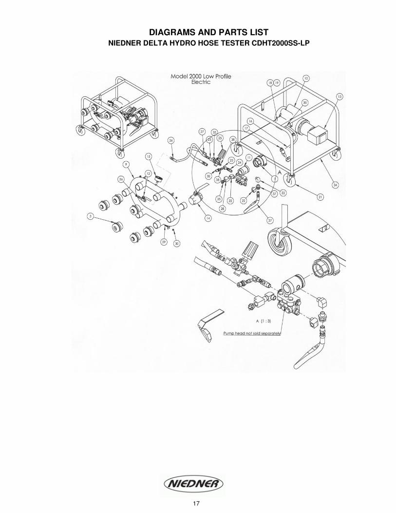
DIAGRAMS AND PARTS LIST
NIEDNER DELTA HYDRO HOSE TESTER CDHT2000SS-LP
17

No. Qty Code Description No. Qty Code Description
1 1 CA3500020B25B 2” NH x 2.5” NH DSW Fem 22 3 DEL-1052 Street elbow ½” 90°
3 6 DEL-52002 Check valve assembly 2.5” NH 23 2 DEL-1055 Street elbow 3/8” 90°
9 1 DEL-1015-51 Manifold 2000 24 1 DEL-1058 Brass 3 connect tee 3/8”
10 1 DEL-1121 Motor 1.7 HP 25 1 DEL-1062 Pressure Regulator (unloader)
11 1 DEL-1033 Inlet Nipple 2" NH 26 1 DEL-1064 Hose 3/8” x 18"
12 1 DEL-1034 Ball valve ¼" 27 2 DEL-1066 Hose ½” x 15"
13 1 DEL-1036 Pump 4.3 GPM 28 1 DEL-1068 Brass 3 connect run tee ½”
14 1 DEL-1038 Ball valve 2" 32 1 DEL-1087M Quick connect male
15 1 DEL-1039-01 Gauge 1000 PSI 33 1 DEL-1098 Reducer ½” F x ¼” M
16 1 DEL-1041/21 Electric Cord 14/3 x 7 m 120V 34 1 DEL-1109 Stainless steel – low profile
18 1 DEL-1042 Toggle switch 35 1 DEL-1120 Thermal relief valve
19 1 DEL-1043 Toggle switch boot 36 1 DEL-1138 ¼” Hex Nipple
20 1 DEL-1045-14/3 Strain relief connector 37 1 DEL-1181 In line strainer unit
21 4 DEL-1049 Wheels 5" 38 2 DEL-2050 Hex pipe nipple 3/8"
1 Del-1046/120V GFCI Module 120v
PARTS LIST NIEDNER DELTA HYDRO HOSE TESTER – CDHT2000SS-LP
18

DIAGRAMS AND PARTS LIST
NIEDNER DELTA HYDRO HOSE TESTER CDHT2000GA-SS
No. Qty Code Description No. Qty Code Description
1 1 CA3500020B25B 2” NH x 2.5“ NH DSW Fem 22 1 DEL-1068 Brass 3 connect run tee ½”
3 6 DEL-52002 Check valve assembly 2.5” NH 26 2 DEL-1076 Wheel push cap
9 1 DEL-1015 Manifold 2000 28 1 DEL-1087M Quick connect male
10 1 DEL-1022 Motor 5.5 HP HONDA 29 1 DEL-1098 Reducer ½” F x ¼” M
11 1 DEL-1033 Inlet Nipple 2" NH 30 1 DEL-1120 Thermal relief valve
12 1 DEL-2033 Pump 5.6 GPM 31 1 DEL-1039-01 Gauge 1000 PSI
13 1 DEL-1034 Ball valve ¼" 32 1 DEL-1138 ¼” Hex Nipple
14 1 DEL-1038 Ball valve 2" 33 1 DEL-1012 Stainless steel – stand up
15 2 DEL-105 Wheels 8" 34 2 DEL-1155-01 Plastic cap for legs
16 2 DEL-1052 Street elbow ½” 90° 35 1 DEL-1013-01 Face plate 2000 - stainless
17 2 DEL-1055 Street elbow 3/8” 90° 36 1 DEL-1181 In line strainer unit
18 1 DEL-1058 Brass 3 connect tee 3/8” 37 2 DEL-2050 Hex pipe nipple 3/8"
19 1 DEL-1062 Pressure Regulator (unloader) 39 2 DEL-1107 Clamp
20 1 DEL-1064 Hose 3/8” x 18" 40 2 DEL-1025 Bracket
21 2 DEL-1066 Hose ½” x 15" 41 2 DEL-2053 45° ¼” Elbow
19

No. Qty Code Description No. Qty Code Description
1 1 CA3500020B25B 2” NH x 2.5“ NH DSW Fem 20 1 DEL-1064 Hose 3/8” x 18"
3 6 DEL-52002 Check valve assembly 2.5” NH 21 2 DEL-1066 Hose ½” x 15"
9 1 DEL-1015 Manifold 2000 22 1 DEL-1068 Brass 3 connect run tee ½”
10 1 DEL-1022 Motor 5.5 HP HONDA 28 1 DEL-1087M Quick connect male
11 1 DEL-1033 Inlet Nipple 2" NH 29 1 DEL-1098 Reducer ½” F x ¼” M
12 1 DEL-2033 Pump 5.6 GPM 30 1 DEL-1120 Thermal relief valve
13 1 DEL-1034 Ball valve ¼" 31 1 DEL-1132-01 Gauge 1000 PSI
14 1 DEL-1038 Ball valve 2" 32 2 DEL-1138 ¼” Hex Nipple
15 4 DEL-1049 Wheels 5” 33 1 DEL-1109 Stainless steel
16 2 DEL-1052 Street elbow ½” 90° 35 1 DEL-1013-01 Face plate 2000 - stainless
17 2 DEL-1055 Street elbow 3/8” 90° 36 1 DEL-1181 In line strainer unit
18 1 DEL-1058 Brass 3 connect tee 3/8” 37 2 DEL-2050 Hex pipe nipple 3/8"
19 1 DEL-1062 Pressure Regulator (unloader)
CDHT2000GA-SS-LP
PARTS LIST NIEDNER DELTA HYDRO HOSE TESTER
CDHT200GA-SS-LP
20
DIAGRAMS AND PARTS LIST
NIEDNER DELTA HYDRO HOSE TESTER CDHT3500SS
21

No. Qty Code Description No. Qty Code Description
1 1 CA3500020B25B 1.5 NH x 1.5 NH DSW 23 1 DEL-1068 Brass 3 connect run tee ½”
3 6 DEL-52002 Check valve assembly 2.5” 26 2 DEL-1076 Wheel push cap
9 1 DEL-1015 Manifold 2000 28 1 DEL-1087M Quick connect male
10 1 DEL-1033 Inlet Nipple 2" NH 29 1 DEL-1098 Reducer ½” F x ¼” M
11 1 DEL-1034 Ball valve ¼" 30 1 DEL-1120 Thermal relief valve
12 1 DEL-1038 Ball valve 2" 31 1 DEL-1132-01 Gauge 1000 PSI
13 1 DEL-1041/240V Electric cord 32 2 DEL-1138 ¼” Hex Nipple
14 1 DEL-1042/240V Cam switch 240V 33 1 DEL-1012 Cart – stand up - stainless
15 1 DEL-1045/240V Strain relief connection 34 2 DEL-1155-01 Plastic cap for legs
16 2 DEL-1051 Wheels 8" 35 1 DEL-1013-01 Face plate 2000 – for stainless
17 2 DEL-1052 Street elbow ½” 90° 36 1 DEL-1181 In line strainer unit
18 2 DEL-1055 Street elbow 3/8” 90° 37 1 DEL-2030 Motor 4.0 HP, 240V
19 1 DEL-1058 Brass 3 connect tee 3/8” 38 1 DEL-2031 Attachment for motor
20 1 DEL-1062 Pressure Regulator (unloader) 39 1 DEL-2032 Pump 5.6 GPM
21 1 DEL-1064 Hose 3/8” x 18" 40 2 DEL-2050 Hex pipe nipple 3/8"
22 2 DEL-1066 Hose ½” x 15" 41 1 DEL-2065 Union ¼” Female-Female1
1 DEL-1046 GFCI Module 120v 2 DEL-1025 Lower bracket
2 DEL-1077 Clamp
PARTS LIST NIEDNER DELTA HYDRO HOSE TESTER - CDHT3500SS
22

23