instructions for using sensor muli6s modulefile.espritmodel.com/documents/pdf/jeti-muli6s-ex.pdf ·...
TRANSCRIPT

INSTRUCTIONS FOR USING
SENSOR MULI6S MODULE
Producer JETI model s.r.o 14.12.2017

Instructions manual: MULi6s Module
CONTENTS
1. DESCRIPTION................................................................................................................................3
2. SENSOR CONNECTION MULI6S MODULE..............................................................................3
3. MULi6s Module SENSOR CONNECTION OPTION....................................................................6
3.1. Jetibox...........................................................................................................................................................6
3.2. Receiver.........................................................................................................................................................6
4. MENU JETIBOX.............................................................................................................................7
4.1. Actual values.................................................................................................................................................7
4.2. Min / Max......................................................................................................................................................8
4.3. Settings..........................................................................................................................................................8
4.4. Alarms...........................................................................................................................................................8
4.5. Service...........................................................................................................................................................8
5. CONFIGURATION USING A DC / DS TRANSMITTER............................................................9
5.1. Telemetry.......................................................................................................................................................9
5.2. Telemetry Min / Max..................................................................................................................................10
6. FIRMWARE UPDATE..................................................................................................................10
7. SPECIFICATIONS........................................................................................................................11
8. GUARANTEE................................................................................................................................11
2

Instructions manual: MULi6s Module
1. Description:
The MULi6s Module is a sensor designed to monitor the Li-XX battery voltage, which measures the
voltage of each battery cell via the balance connector. It allows you to monitor the voltage of up to
6 Li-XX cells per module. The individual MULi6s modules can be serialized and can be connected to
up to 5 modules. The MULi6s Module sensor monitors the voltage of each battery cell with its history
(minimum, maximum), the total battery voltage, the voltage difference between the strongest and the
weakest cells, and the sensor is able to alert the operator to exceed the set parameters by means of alarms.
Sensor information is transmitted by the Duplex system to the operator.
The Duplex system uses a 2.4GHz bandwidth to communicate, not only to the model, but also to the
transmitter. The telemetry data acquired during operation is transmitted in real time and the current state
of the measured quantities can be displayed on the JETIBOX LCD or DC / DS transmitters.
2. Sensor connection Muli6s Module:
Notice! Try to follow the following connection procedure:
1. Connect the MULi6s Module sensor to the Li-XX battery connector.
(Make sure the connector polarity is correct!)
2. Connect the MULi6s Module sensor to the receiver / Expander via the JR connector
3. Connect the negative pole (-) of the battery to the controller / BEC
4. Connect the positive pole (+) of the battery to the controller / BEC
Sensor MULi6s Module connects the battery module to the battery via the balance connector. The
balance connector must be wired as shown below. When the monitored battery is connected to the sensor,
identification of the number of cells is started and, after 3 seconds, the sensor locks into the number of
cells detected. The sensor is always locked until it is switched off. Re-connecting the sensors to the power
supply will lead to a new identification process. If the sensor is locked, any change detected in the
number of connected cells will cause a fault. The fault is indicated by a red LED. The change can also be
detected by means of set alarms directly in the sensor via the Jetibox (see chapter Alarms) or the alarms
set in the DC / DS transmitter (see Chapter Configuration using the DC / DS transmitter).
3

Instructions manual: MULi6s Module
Battery cells are connected from "1" to "6", unless the connection is maintained and the sensor is
powered, the red LED lights up. The sensor is powered either from the first two battery cells or from
the receiver via the EXT output, whichever is the higher the supply voltage.
If we only want to view the status of the battery, we do not have to connect the receiver or the Jetibox, the
green LEDs will first show which cells are connected and then the status of the weakest cell of the
module is on. The LEDs are graded according to the cell voltage according to the following table:
After a while the green LED goes out and the module goes into sleep mode with low power consumption.
It can be put into normal mode by connecting a receiver or a Jetibox (powered). After this "wake up", the
status of the connected inputs and the state of the weakest cell of the module are displayed, the LEDs will
go out after a while. Then, the LED always lights for 0.3s and displays the state of the weakest cell to
save the potential of the first two cells. To put the module back into "sleep" mode, just unplug the
receiver or Jetibox (or their power supply).
If we connect the module to the receiver without connected batteries, we can, for example, read the last
recorded minimum and maximum on the Jetibox independently of the "trigger level" sensor setting (no
additional modules attached). With this module connected, all the LEDs light up for a while and then go
out, so the module indicates that it is OK. The module has, in addition to input connectors, a balance
connector for cells, one output and one optically isolated input. The output - a twisted triple end
terminated by a black JR connector, connects the Jetibox or the receiver. On the input - a three-wire with
a pitch of 2.54mm, another module can be connected. This input will connect the output (twisted three-
wire with JR connector) from the next module. The modules can be chained in series.
4
0 – 3,3V 1 LED
3,3 – 3,5V 2 LED
3,5 – 3,7V 3 LED
3,7 – 3,9V 4 LED
3,9 – 4,1V 5 LED
4,1V and more 6 LED

Instructions manual: MULi6s Module
Notice! Only use wires that are part of the sensor for serial connection of modules.
5

Instructions manual: MULi6s Module
3. MULi6s Module sensor connection options:
1. The MULi6s Module three-wire sensor cable with the JR connector can be connected directly to
the JETIBOX (connector labeled Impulse,+ -). Use the second JETIBOX input, which is marked
(+ -), to bring the supply voltage. This connection does not use wireless data transmission and the
measured values are displayed directly on the JETIBOX LCD. This connection does not allow the
generation of alarms because the siren is part of a transmitter module that is not connected in this
case. Alarms are only displayed on the LCD.
2. Connect the 3-wire MULi6s Module sensor cable with the JR connector to the DUPLEX receiver
connector on the rear (marked Ext.). The MULi6s Module sensor is powered from the receiver.
To set the MULi6s Module sensor parameters, connect the JETIBOX to the transmitter module
and turn on the DUPLEX receiver and transmitter. You can also set this sensor using the Jeti DC /
DS transmitter in Menu / Model / Device Explorer.
Incorrect connection procedure: The module connects to the disconnected receiver or the Jetibox and
the battery is connected.
6

Instructions manual: MULi6s Module
Notice! The module that connects to the powered receiver is automatically set as Master. Otherwise, it
has Slave status. For the proper operation of the module as a Master, the power supply to the connected
receiver must also be connected for the first time after connecting the battery. If the battery and receiver
power are disconnected, the process described above will have to be performed after reconnecting the
battery. While the receiver is connected to the sensor while the receiver is switched off and the module is
not yet identified as Master, the battery module removes a higher current of approximately 0.5mA. After
identifying and disconnecting the receiver's power, this current is 70uA, see chapter Technical data.
The same procedure as the receiver applies to Jetibox and other connected devices on the EXT output of
the MULi6s Module sensor. So if only the battery is connected to the sensor, the sensor is set to Slave and
takes the type 70uA. If the receiver is connected to the sensor in addition to the battery or the Jetibox, the
sensor will take 0.5mA until the power supply of the receiver or Jetibox is connected, then after
disconnecting the receiver power, the sensor behaves like a 70uA Master.
Slave is always powered by his first two cells.
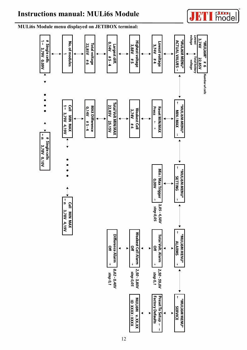
4. Menu JETIBOX:
The JETIBOX terminal (or Device Explorer in the Jeti DC / DS transmitter) is used to set parameters and
read data. When connected to the MULi6s Module, a startup screen appears, which contains the sensor
identification and the number of connected battery cells on the first row of the sensors of all connected
modules. The second line shows the lowest voltage from the connected cells and the total battery voltage.
When the power supply is connected to the sensor via EXT, the "initialization" message is displayed for a
short time on this line, when all the articles are read, after which the inscription disappears.
Pressing R (right) for 2 seconds will cause the Min / Max value to be cleared. Press the D (down)
button on the JETIBOX to enter the MULi6s Module sensor menu.
4.1. MULi6s Module MENU mode: ACT. VALUES - Press D (down arrow) to select the current
measured values
Lowest voltage - shows the current voltage of the lowest voltage cell of all connected cells and the
weakest cell number.
Highest voltage - displays the current voltage of the highest voltage cell of all connected cells and the
number of the strongest cell.
Largest difference - Displays the current voltage difference between the weakest and the strongest
cells. In addition to the voltage, it also shows the numbers of the cells between which this difference
is measured. The first number corresponds to the strongest article.
Total voltage - shows the current total battery voltage and the number of all connected cells.
No. of modules - displays the current number of connected modules.
Single cells - Displays the current voltage of individual cells and their voltage difference from the
strongest cell. Use R and L to select the article number that we want to view.
7

Instructions manual: MULi6s Module
4.2. MULi6s Module MENU: MIN / MAX - Press D (Down Arrow) to select the display of the
voltage extremes recorded during the measurement. Extreme recording is automatically deleted
according to the trigger settings in the "Settings" menu or can be deleted manually.
Reset Min / Max - simultaneously pressing the R and L arrows (right and left) deletes the record of
the measured minimum and maximum parameters.
Weakest Cell - Featuring the weakest cell for the entire flight - its voltage and cell number.
Total Volt MIN / MAX - Shows the minimum and maximum total battery voltage measured over the
entire flight.
MAX Difference - Displays the greatest voltage difference between the weakest and strongest cells
throughout the flight. In addition to the voltage, which of the two cells this difference affects, the first
number corresponds to the strongest cell.
Cell MIN MAX - Displays the minimum and maximum voltages of the currently selected cell. Use R
and L to select the cell number that we want to view.
4.3. MULi6s Module MENU MODE: SETTINGS - Press D (down arrow) to enter the basic setting
of the sensor.
Min Max Trigger - Set the voltage value for which the minimum and maximum will be reset when
the sensor is switched on for the first time.
4.4. MULi6s Module MENU: ALARMS - Press the D (Down Arrow) button to enter the individual
alarm settings. If a set parameter is exceeded, then the JETIBOX LCD in the main menu on the
second line will alternately display the original display with the corresponding alarm, while the
red LED will illuminate at the time of the alarm display. If the alarm is set to "Off", the alarm is
off. If multiple alarms occur at the same time, they are displayed on the second line of the
JETIBOX.
Total Voltage Alarm - Low battery alarm setting. If the measured total battery voltage drops below
the set value, an alarm is activated.
Weakest Cell Alarm - Set low-voltage signalling for the cell. If the measured voltage of any cell
falls below the set value, the alarm is activated.
Difference Alarm - Alarm signalling for a large voltage difference between the strongest and the
weakest cells. If the measured voltage exceeds the set value, the alarm is activated.
4.5. MULi6s Module MENU MODE: SERVICE - Press the D (down arrow) key to enter the
firmware version display and restore the default sensor settings.
Factory Defaults - Press R and L (right and left) simultaneously to upload the MULi6s Module
sensor default setting.
MULi6s Modul v. Xx.xx ID xxxxx : xxxxx – Product name with firmware version and serial
number (ID).
8

Instructions manual: MULi6s Module
5. Configuration using a DC / DS transmitter:MULi6s Module can be configured via the DC / DS transmitter via the Connected Devices menu.
In order to configure MULi6s via the transmitter, it is necessary to observe:
• Firmware version of Duplex 3.12 and later (with Output mode setting -> EX bus).
• Receiver connected to MULi6s Module with EX Bus.
• Transmitter firmware version 2.02 and later + device profile (MULi6M.bin) recorded in the
"Devices" directory on the transmitter SD card.
• If everything is properly plugged in, or configured, the MULi6s Module entry appears in the
Connected Devices menu. Entering this item will go to the configuration menu.
• Reset to factory defaults - to retrieve the default MULi6s Module setting.
5.1. Telemetry
• Total voltage - shows the current total battery voltage and the number of all connected cells
• Number of cells - shows the current number of connected cells
• Number of modules - displays the current number of connected modules
• The weakest link - displays the weakest link for the entire flight - its voltage and cell number
• Largest difference - shows the current voltage difference between the weakest and the strongest
cell. In addition to the voltage, it also shows the numbers of the cells between which this
difference is measured. The first number corresponds to the strongest cell.
• Telemetry of all cells - displays all connected cells and their current voltage difference between
the weakest and the strongest cells.
9

Instructions manual: MULi6s Module
5.2. Telemetry Min/Max
• Clear MIN / MAX switch - Assigns the controller to the DC / DS transmitter, commanded to
erase the minimum and maximum MULi6s Module.
• Clear now - instantly reset the minimum and maximum MULi6s module.
• MIN / MAX Trigger - setting the voltage value, at which the minimum and maximum will be
reset when the sensor is switched on for the first time.
• Total voltage MIN - shows the total minimum battery voltage measured over the entire flight.
• Total voltage MAX - Displays the total maximum battery voltage measured over the entire flight.
• MIN of the weakest cell - Displays the minimum voltage of the weakest cell for the entire flight
time and the cell number.
• MAX Difference - Displays the greatest voltage difference between the weakest and strongest
cells throughout the flight. In addition to the voltage, which of the two cells this difference affects,
the first number corresponds to the strongest cell.
• MIN/MAX Telemetry of all cells - displays all connected cells and their minimum and maximum
voltage.
6. Firmware Update:MULi6s Module allows you to update your firmware via your computer. Updates are done via the JETI USB
Adapter.
Procedure:
• On the website www.jetimodel.cz in the download section, you will find a program for
updating with the latest firmware. Save it to your computer.
• Connect the USB adapter to the computer. The procedure of installing drivers for the USB
adapter is to be found in the user manual for the USB adapter. Run the firmware update
program on your PC.
• Run the firmware update program on your PC.
• Connect the USB adapter with a 3-wire cable to the Ext port on the MULi6s Module
(black JR connector).
• The program identifies the connected device and automatically updates.
10

Instructions manual: MULi6s Module
7. Specification:
Technical parameters MULi6s Module
Dimensions 33 x 18 x 5 mm
Weight with wires 6 g
Measurement range per cell typ. 0-4,4V
Accuracy of measurement +-1%
Operating temperature - 10°C až + 85° C
Supply voltage 4 – 8,4V
Consumption 25 mA
Sleep Mode Consumption 70uA
Maximum of connected modules 5
Number of batteries connected to one module 1
Maximum number of cells connected to one module 6
Maximum voltage on one module 26,4V
8. Guarantee
The product is warranted 24 months from the date of sale, provided it has been operated in accordance
with this manual, to the prescribed voltage and is not mechanically damaged. The warranty and post-
warranty service is provided by the manufacturer: JETI model s.r.o. Příbor, www.jetimodel.cz
11
Instructions manual: MULi6s Module
MULi6s Module menu displayed on JETIBOX terminal:
12