instructions for use - w&h - w&h dentalwerk
TRANSCRIPT

LINA MB 201 11 ENG - Rev. 3.1
Posizione logo
Instructions for useInstructions for useInstructions for useInstructions for use
MB17 / MB22
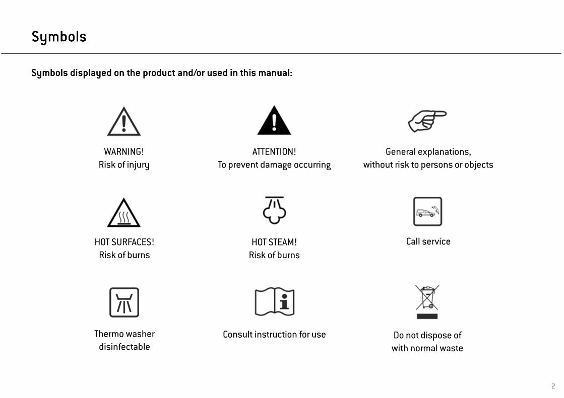
Symbols displayed on the product and/or used in this manual:Symbols displayed on the product and/or used in this manual:Symbols displayed on the product and/or used in this manual:Symbols displayed on the product and/or used in this manual:
WARNING!
Risk of injury
ATTENTION!
To prevent damage occurring
General explanations,
without risk to persons or objects
HOT SURFACES!
Risk of burnsHOT STEAM!
Risk of burns
Call service
Thermo washer
disinfectableConsult instruction for use Do not dispose of
with normal waste
SymbolsSymbolsSymbolsSymbols
2

ContentsContentsContentsContents
3
1. Introduction . . . . . . . . . . . . . . . . . . . . . . . . . . . . . . . . . . . . . . . . . . . . . . . . . . . . . . . . . . . . . . . . . . . . . . . . . . . . . . . . . . . . . . . . . . . . . . . . . . . . . 4
2. Unpacking . . . . . . . . . . . . . . . . . . . . . . . . . . . . . . . . . . . . . . . . . . . . . . . . . . . . . . . . . . . . . . . . . . . . . . . . . . . . . . . . . . . . . . . . . . . . . . . . . . . . . . . 6
3. Safety advice . . . . . . . . . . . . . . . . . . . . . . . . . . . . . . . . . . . . . . . . . . . . . . . . . . . . . . . . . . . . . . . . . . . . . . . . . . . . . . . . . . . . . . . . . . . . . . . . . . . . 8
4. Installation and start-up . . . . . . . . . . . . . . . . . . . . . . . . . . . . . . . . . . . . . . . . . . . . . . . . . . . . . . . . . . . . . . . . . . . . . . . . . . . . . . . . . . . . . . . . . . 9
5. Programming . . . . . . . . . . . . . . . . . . . . . . . . . . . . . . . . . . . . . . . . . . . . . . . . . . . . . . . . . . . . . . . . . . . . . . . . . . . . . . . . . . . . . . . . . . . . . . . . . . . . 18
6. Running a sterilization cycle . . . . . . . . . . . . . . . . . . . . . . . . . . . . . . . . . . . . . . . . . . . . . . . . . . . . . . . . . . . . . . . . . . . . . . . . . . . . . . . . . . . . . 24
7. Maintenance . . . . . . . . . . . . . . . . . . . . . . . . . . . . . . . . . . . . . . . . . . . . . . . . . . . . . . . . . . . . . . . . . . . . . . . . . . . . . . . . . . . . . . . . . . . . . . . . . . . . 37
8. Troubleshooting, alarms and messages . . . . . . . . . . . . . . . . . . . . . . . . . . . . . . . . . . . . . . . . . . . . . . . . . . . . . . . . . . . . . . . . . . . . . . . . . . . 46
9. Recycling and disposal . . . . . . . . . . . . . . . . . . . . . . . . . . . . . . . . . . . . . . . . . . . . . . . . . . . . . . . . . . . . . . . . . . . . . . . . . . . . . . . . . . . . . . . . . . 54
APPENDICES
1 Technical data . . . . . . . . . . . . . . . . . . . . . . . . . . . . . . . . . . . . . . . . . . . . . . . . . . . . . . . . . . . . . . . . . . . . . . . . . . . . . . . . . . . . . . . . . . . . . . . . . . . 55
2 Maintenance of dental handpieces . . . . . . . . . . . . . . . . . . . . . . . . . . . . . . . . . . . . . . . . . . . . . . . . . . . . . . . . . . . . . . . . . . . . . . . . . . . . . . . 56
3 Sterilization load preparation . . . . . . . . . . . . . . . . . . . . . . . . . . . . . . . . . . . . . . . . . . . . . . . . . . . . . . . . . . . . . . . . . . . . . . . . . . . . . . . . . . . . . 57
4 Bowie & Dick test . . . . . . . . . . . . . . . . . . . . . . . . . . . . . . . . . . . . . . . . . . . . . . . . . . . . . . . . . . . . . . . . . . . . . . . . . . . . . . . . . . . . . . . . . . . . . . . . 59
5 Helix test . . . . . . . . . . . . . . . . . . . . . . . . . . . . . . . . . . . . . . . . . . . . . . . . . . . . . . . . . . . . . . . . . . . . . . . . . . . . . . . . . . . . . . . . . . . . . . . . . . . . . . . . 60
6 Vacuum test . . . . . . . . . . . . . . . . . . . . . . . . . . . . . . . . . . . . . . . . . . . . . . . . . . . . . . . . . . . . . . . . . . . . . . . . . . . . . . . . . . . . . . . . . . . . . . . . . . . . . 61
7 Water quality . . . . . . . . . . . . . . . . . . . . . . . . . . . . . . . . . . . . . . . . . . . . . . . . . . . . . . . . . . . . . . . . . . . . . . . . . . . . . . . . . . . . . . . . . . . . . . . . . . . . 62
8 Example of a cycle data report . . . . . . . . . . . . . . . . . . . . . . . . . . . . . . . . . . . . . . . . . . . . . . . . . . . . . . . . . . . . . . . . . . . . . . . . . . . . . . . . . . . . 63
9 Accessories and spare parts . . . . . . . . . . . . . . . . . . . . . . . . . . . . . . . . . . . . . . . . . . . . . . . . . . . . . . . . . . . . . . . . . . . . . . . . . . . . . . . . . . . . . . 64
10 Helix test documentation form . . . . . . . . . . . . . . . . . . . . . . . . . . . . . . . . . . . . . . . . . . . . . . . . . . . . . . . . . . . . . . . . . . . . . . . . . . . . . . . . . . . . 71
1. 1. 1. 1. IntroductionIntroductionIntroductionIntroduction
For your safety and the safety of your patientsFor your safety and the safety of your patientsFor your safety and the safety of your patientsFor your safety and the safety of your patientsThe purpose of this manual is to provide you with information about LINA MB17/22 sterilizers to ensure:• proper installation and set-up;• optimal use;• safe and reliable operation;
• compliance with regular maintenance and servicing requirements.
4
Intended use of the productIntended use of the productIntended use of the productIntended use of the productSmall steam sterilizers are widely used for medical purposes, e.g. in general medical practices, dentistry, facilities for personal hygiene and beauty care and also veterinary practices. They are also used for materials and equipment, which are likely to come into contact with blood or body fluids, e.g. implements used by beauty therapists, tattooists, body piercers and hairdressers.
The devices is intended for professional use only by trained people.
About this manualAbout this manualAbout this manualAbout this manualAll drawings, images and texts contained in this manual are the property of the manufacturer.All rights reserved. Even partial duplication of drawings, images or text is prohibited.
The information contained in this document is subject to change without prior notice.
Responsibility of the manufacturerResponsibility of the manufacturerResponsibility of the manufacturerResponsibility of the manufacturerThe manufacturer can only accept responsibility for the safety, reliability and performance of the product when the product itself is installed, used and serviced in accordance with these instructions for use.
Servicing by unauthorized persons invalidates all claims under warranty and any other claims.
Please carefully read the safety information in Chapter 3!

Qualifications of the usersQualifications of the usersQualifications of the usersQualifications of the usersThere are two types of users who may operate the sterilizer:
The Advanced user The Advanced user The Advanced user The Advanced user is the head of the clinic/practice, who is legally responsible for the efficiency of the hygiene protocol in place as well as the sterilization process. He/she is also responsible for the USERS’ training and the correct operation and maintenance of the equipment.
The UsersThe UsersThe UsersThe Users are the persons who use the sterilizer according to the ADVANCED USER’s instructions. They must be trained in operating
the sterilizer and in its safe use. Training must be regular and evidence of the understanding shall be recorded.
Conformity to European Standards and DirectivesConformity to European Standards and DirectivesConformity to European Standards and DirectivesConformity to European Standards and Directives
Medical Device Directive 93/42/CEE for devices class IIb, in accordance with the Rule 15 – Appendix IX of the above
Directive.
Directive 97/23/CEE (PED – Pressure Equipment Directive) for every sterilization chamber designed and manufactured in
conformity to the Appendix 1 and to the procedure described in the form D1 Annex III.
Directive 2002/96/CEE (RAEE) for disposal of parts coming from electrical or electronic products.
European standard EN13060 (small water steam sterilizers).
See the Declaration of Conformity and the Warranty Card in the enclosed documents.
IntroductionIntroductionIntroductionIntroduction
5

2. Unpacking2. Unpacking2. Unpacking2. Unpacking
If the sterilizer comes from a cold location, wait until all external and internal surfaces are free from moisture before switching it ON.The sterilizer must be removed from the box and transported by two people.Weight: LINA MB17: 38 kg
LINA MB22: 40.5 kg
Check the external conditions of the box and the sterilizer. In case of any damage, immediately contact your dealer or the shipping agent that has carried out the
transport.
Open the front door.
All the accessories are in the sterilization chamber.
Remove all items except the trays and the tray rack.
6
The packaging of the product is environmentally friendly and can be disposed of by industrial recycling companies.
However, we recommend to keep the original packaging should you ever have to ship
or transport the sterilizer.

Contents of the packageContents of the packageContents of the packageContents of the package
Tray (3 pieces total)
Reversible rack
Tray holder
Drain tube
Mains cable
Funnel
Wall spacer
Fast guideDeclaration of conformityDocumentation CDWarranty card
Works tests report
7

3. Safety advice3. Safety advice3. Safety advice3. Safety advice
8
• The user is responsible for the proper installation, the correct use and maintenance of the sterilizer in accordance with theinstructions listed in this manual.
• The sterilizer has not been designed for the sterilization of foodstuff or waste.• Liquids may be sterilized only if the appropriate option is installed.• The sterilizer must not be used in presence of explosive or flammable gases, vapours, liquids or solids.• The chamber is automatically heated up to high temperature as soon as the sterilizer is switched on – risk of burns!• Ensure that the socket the mains cable is connected to is properly grounded.• The trays and the sterilization load will be hot at the end of each cycle. Use tray or cassette holders to empty the
sterilization chamber.• Do not exceed the maximum load weight limits as specified in this manual (see Chapter 6 of the Instructions for use).• Do not remove the name plate or any label from the sterilizer.• To avoid electrical short circuits, do not pour water or any other liquids over the sterilizer.• Switch off the sterilizer and unplug the mains cable before inspecting, carrying out maintenance or servicing the sterilizer.• The low-voltage outlet in the rear of the sterilizer is for the connection of specific accessories only: do not connect any
device other than those specifically supplied by the manufacturer.• All electric devices connected to the sterilizer shall be of Insulation Class II (double insulated) or higher.• Repairs, maintenance or service must be carried out by service technicians authorized by the manufacturer and using
genuine spare parts only.• In case of transport:
– Completely drain both water tanks (see section “Water Tanks” in Chapter 4 of the Instructions for use).– Allow the sterilization chamber to cool down.
– Use original or appropriate packaging.

4. Installation and start4. Installation and start4. Installation and start4. Installation and start----upupupup
9
Required minimum clearancesRequired minimum clearancesRequired minimum clearancesRequired minimum clearancesBack side: 50mmRight and left sides: 10 mm
Upper side: As required for filling the water tank, 50 mm minimum
PlacementPlacementPlacementPlacementPlace the sterilizer on a flat and level surface, far from sources of heat and from flammable materials.Do not place the sterilizer so that it is difficult to open the service door and operate on the controls in it.Do not place the sterilizer so that it is difficult to disconnect the power supply plug.Place the sterilizer in a well ventilated room.If installed in a cabinet, this shall be provided with an opening of at least 200x150 mm on the rear side.The sterilizer must not be operated in presence of explosive atmospheres.
Electrical connectionElectrical connectionElectrical connectionElectrical connectionThe electrical power supply to the sterilizer must fulfil all applicable standards in the country of use,
and must comply with the data label on the back of the sterilizer.
Connect the cord set to the socket provided in the back of the sterilizer.
Connect the mains cable to a wall outlet with the following characteristics:• Single - phase 200 - 240 V, 50/60 Hz, 8,75 A, on a dedicated circuit;• Overvoltage category = II;• 10 A differential circuit breaker with a sensitivity of 30 mA. The circuit breaker must be a certified
type according to applicable norms;• Maximum power consumption of the sterilizer is 1750 W;
• A grounded connection is essential.

Water tanksWater tanksWater tanksWater tanks
Filling the clean water tankFilling the clean water tankFilling the clean water tankFilling the clean water tank• Switch the sterilizer ON• Slide the tank cover to the right to access the clean water tank inlet.• Remove the cap from the tank inlet;• Insert the funnel and fill the water tank with app. 3.5 litres of distilled or demineralized water;• Once the clean water tank is almost full, an audible tone will sound; stop filling;• Place the cap to close the tank;
• Slide the tank cover back into its original position.
10
Draining the used and clean water tankDraining the used and clean water tankDraining the used and clean water tankDraining the used and clean water tank• Open the service door at the front of the sterilizer.• Put a container (4 litres min) below the sterilizer and insert into it the free end of the drain tube.• Insert the drain tube into the right connector (grey) for the used water, or into the left connector
(blue) for the clean water.• Let the water flow from the tank completely.• Press the push-button on top of the quick connector to dislodge the drain tube.
Use only high quality distilled or demineralized water (see Appendix 7Use only high quality distilled or demineralized water (see Appendix 7Use only high quality distilled or demineralized water (see Appendix 7Use only high quality distilled or demineralized water (see Appendix 7).).).).
Do not add any chemical / additive to the water. Do not add any chemical / additive to the water. Do not add any chemical / additive to the water. Do not add any chemical / additive to the water.

Chamber furnitureChamber furnitureChamber furnitureChamber furniture
11
The chamber furniture consists of the traystraystraystrays, the tray rack tray rack tray rack tray rack and the steam diffuser plate.steam diffuser plate.steam diffuser plate.steam diffuser plate.
Tray rackTray rackTray rackTray rackInsert the rack into the sterilizer chamber, align it at the center/bottom of the chamber and push it gently
into position until it clicks.
If inserted in a 90° degree rotated position, the rack holds 3 trays or 3 cassettes horizontally.
Usable space in the chamberUsable space in the chamberUsable space in the chamberUsable space in the chamberLINA MB17: 195 x 195 x 297mm (WxHxD); equal to the volume of 11.5 litres.LINA MB22: 195 x 195 x 390mm (WxHxD); equal to the volume of 15 litres.
Before touching the chamber furniture, ensure the sterilization chamber is cold: risk of burns!
1
2
The chamber rack is reversible and can accommodate 5 trays horizontally or 3 cassettes vertically.
Sterility at the end of the cycle is not guaranteed if the steam diffuser plate was not correctly placed.To hookTo hookTo hookTo hook the steam diffuser plate, slide it into the chamber until it gets engaged into the end hooks.To removeTo removeTo removeTo remove the steam diffuser plate, press it in the center of the end edge (1) and slide it outwards (2).
Steam diffuser plateSteam diffuser plateSteam diffuser plateSteam diffuser plateEnsure that the steam diffuser plate is firmly hooked in its position before starting a sterilization cycle. An improper positioning of the steam diffuser plate could result in bad steam quality and could impair the sterilization process, with risk of non sterile load and cross infection.

Controls and commandsControls and commandsControls and commandsControls and commands
Mains switch
Bacteriological filter
Clean water drain (blue) Used water drain (grey)
Display
Water tank cover
Tank filling cover - cap
Door pin
Sterilization chamber
Door seal
Chamber door
Dust filter
Service door
Control panel
Front viewFront viewFront viewFront view Service doorService doorService doorService door
12

Controls and commandsControls and commandsControls and commandsControls and commands
13
Water supply inlet
Used water drain
Rear viewRear viewRear viewRear view
Condenser vent
Mains cable guide
Mains plug socket
Serial communication port
Pressure safety valve cover
Accessories power socket
Detail of the hydraulicDetail of the hydraulicDetail of the hydraulicDetail of the hydraulicconnections (optional)connections (optional)connections (optional)connections (optional)

Controls and commandsControls and commandsControls and commandsControls and commands
14
Switching ON the sterilizerSwitching ON the sterilizerSwitching ON the sterilizerSwitching ON the sterilizerPress the mains switch behind the service door to switch ON the sterilizer.The visual indicator on the mains switch turns green and the START screen (see next page) appears.
“SLEEP” mode“SLEEP” mode“SLEEP” mode“SLEEP” modeIf the sterilizer is not used for 12 hours, (the time interval can be changed, see Chapter 5 - Programming) it will automatically switch to “SLEEP” mode.In “SLEEP” mode the display remains dark and the sterilizer chamber is no longer heated to save energy.Exit from “SLEEP” mode through any of the following actions:- Press any button on the control panel;- Open or (if it is open)close the chamber door.
It is also possible to put the sterilizer into “SLEEP” mode manually:On the START screen, press the BACK button.A 10 second countdown will commence. At the end of the countdown the sterilizer will enter the “SLEEP” mode.The countdown can be stopped at any time by pressing the BACK button.

Display and iconsDisplay and iconsDisplay and iconsDisplay and icons
15
Third and fourth linesThird and fourth linesThird and fourth linesThird and fourth lines
Show additional information about the active option/action.
Warning, tank and printer iconsWarning, tank and printer iconsWarning, tank and printer iconsWarning, tank and printer icons
The cursor (>) preceding an icon means that an information message is to be read.
“Padlock” icon“Padlock” icon“Padlock” icon“Padlock” icon
The cursor (>) preceding this icon informs that the door is safely locked.
Second lineSecond lineSecond lineSecond line
Shows the active option/action (preceded by the cursor >).By pressing OK, the active option/action will be selected/executed.
Pressing UP or DOWN changes the active option/action.
First lineFirst lineFirst lineFirst line
Shows the title/purpose of the current page and invites you to take an action (e.g. select a cycle).

IconsIconsIconsIcons
Tank warningTank warningTank warningTank warningThe clean water tank needs to be filled, or the used water tank has to be drained, or a message about the water
quality is present.
General warningGeneral warningGeneral warningGeneral warning
One or more messages require your attention, or an action is required (e.g. maintenance).
PrinterPrinterPrinterPrinter
An external device (printer, PC, etc.) is not working properly, or is OFF, or is disconnected from the sterilizer.
16
Door lockedDoor lockedDoor lockedDoor lockedThe door is locked. During a sterilization cycle this does not indicate any anomaly.
If one or more icons of the display are preceded by the cursor, please take the actions as outlined below:If one or more icons of the display are preceded by the cursor, please take the actions as outlined below:If one or more icons of the display are preceded by the cursor, please take the actions as outlined below:If one or more icons of the display are preceded by the cursor, please take the actions as outlined below:
If an icon is preceded by the cursor, this means that an information message is present in the MESSAGES menu.
Follow the instructions provided in Chapter 8 to read the relevant messages.

Control buttonsControl buttonsControl buttonsControl buttons
UP buttonUP buttonUP buttonUP buttonMoves to the upper item in the list.
Increases a number or a parameter.
ECOECOECOECO----B optionB optionB optionB optionThis label reminds you that, when starting a cycle, you can choose the ECO-B mode by holding the OK button for 2 seconds
(see Chapter 6).
17
OK button (confirmation button)OK button (confirmation button)OK button (confirmation button)OK button (confirmation button)Confirms the active option.Confirms a number or a date.
Saves a configuration or a parameter.
BACK buttonBACK buttonBACK buttonBACK buttonAborts the action/function.Moves to the previous screen without confirming/making any
changes nor saving any parameters.
DOWN buttonDOWN buttonDOWN buttonDOWN buttonMoves to the lower item in the list.
Reduces/decreases a number or a parameter.
The control panel shows four buttons:

18
5. Programming5. Programming5. Programming5. Programming
MenuMenuMenuMenuConfirm (OK) the MENU option to access all sub-menus and navigate through sub-menus with the UP and DOWN buttons.See the following pages for a complete description of the options available and how to use them.
SetupSetupSetupSetupScroll (DOWN) to SETUP and confirm (OK) to access and set the main parameters of the sterilizer. See the following pages for a complete description of the parameters you can set and how to do it.
Initial setupInitial setupInitial setupInitial setupBefore using the sterilizer please program important parameters such as date, time, language, display backlight and contrast.
This is done by means of the SETUP functions.
Start screen and menu optionsStart screen and menu optionsStart screen and menu optionsStart screen and menu optionsWhen the sterilizer is switched ON, or when exiting from SLEEP mode, the default cycle program is displayed, preceded by the cursor.By pressing DOWN the other available cycle programs are displayed.Continuously press DOWN until the MENU option appears.

19
Table 1: list of the MENU optionsTable 1: list of the MENU optionsTable 1: list of the MENU optionsTable 1: list of the MENU options
MENUMENUMENUMENU SUBSUBSUBSUB----MENUMENUMENUMENU WHAT IT DOESWHAT IT DOESWHAT IT DOESWHAT IT DOES
(continues(continues(continues(continueson next on next on next on next page)page)page)page)
---- Displays pending messages. Refer to Chapter 8 for a detailed list of messages.
Select a previously recorded cycle. Press OK and then scroll the list of the recorded cycles with UP /DOWN. Press OK to select the cycle to be viewed or printed.
Displays the selected cycle. Press UP/DOWN to scroll the cycle report.
(*)(*)(*)(*)Prints the selected cycle. Press OK and scroll UP and DOWN to change the number of copies to be printed. Once the value is displayed, press OK to print.
(*)(*)(*)(*)Prints traceability labels for the selected cycle. Press OK and scroll UP and DOWN to change the number of copies to be printed. Once the value is displayed, press OK to print.
(*)(*)(*)(*) Saves a cycle data file on a memory storage device (memory card or PC).
Displays all the alarms that have occurred during sterilization cycles.
(*)(*)(*)(*) Prints all the alarms that have occurred of the sterilization cycles stored in memory.
Sets important parameters of the sterilizer such as date, time, language, etc. Sets important parameters of the sterilizer such as date, time, language, etc. Sets important parameters of the sterilizer such as date, time, language, etc. Sets important parameters of the sterilizer such as date, time, language, etc. Confirm (OK) to access all available options. Refer to TABLE 2 TABLE 2 TABLE 2 TABLE 2 for a detailed list of options and related programming.
(*)(*)(*)(*) Enables the automatic water feed Press UP/DOWN to scroll the YES/NO options, then press OK to enable/disable the function (warning), or BACK to exit without saving.
(*)(*)(*)(*) Enables water quality warnings based on the external/internal sensor(*)(*)(*)(*)
Allows the user to change the current user level. Access to advanced level or service level is protected by codes.See “How to log in as an advanced user” in the following pages.
Allows the user to enter the activation code in order to enable some optional features.
(*) available/effective only if an endorsed device (printer, logger, PC, water supply, etc.) is connected and enabled in the SETUP menu.

20
Table 1: list of the MENU options (continued)Table 1: list of the MENU options (continued)Table 1: list of the MENU options (continued)Table 1: list of the MENU options (continued)
MENUMENUMENUMENU SUBSUBSUBSUB----MENUMENUMENUMENU WHAT IT DOESWHAT IT DOESWHAT IT DOESWHAT IT DOES
(continued (continued (continued (continued from from from from
previouspreviouspreviouspreviouspage)page)page)page)
(*)(*)(*)(*)
Prints traceability labels to be stuck to the load pouches.Labels show the lot number and other parameters as specified in the LOT LABELS menu (see SETUP table). The number of labels will be requested: press UP/DOWN to increment/decrement the number, then press OK to print.After printing, the lot number is incremented by 1.Prints labels of a previous sterilization lot. The lot number and the number of labels will be requested: press UP/DOWN to increment/decrement the numbers, then press OK to print.
Displays the device brand name; e.g. W&H.
Displays the device model name; e.g. LINA MB22.
Displays the serial number of the sterilizer; e.g. 110009.
Displays the total number of cycles executed by the sterilizer.
Displays the status (number of cycles executed) of consumables. Permits the user to resetthe counter to zero after replacing a consumable. See Chapter 7 (Maintenance) for details.
Displays the number of cycles executed compared to the 4000 cycle service.
Displays the number of cycles executed compared to the 20000 cycle service.
Displays the current software version.
Displays the current system software version.
Displays the current version of the power firmware.
Shows the identifier of the hardware key (label printer/service), if connected.
Displays the software version of the PC/logger device, if connected.
(*) available/effective only if an endorsed device (printer, logger, PC, water supply, etc.) is connected and enabled in the SETUP menu.

21
Table 2: Detail of the SETUP optionsTable 2: Detail of the SETUP optionsTable 2: Detail of the SETUP optionsTable 2: Detail of the SETUP options
MENUMENUMENUMENU SUBSUBSUBSUB----MENUMENUMENUMENU WHAT IT DOES AND HOW TO SET ITWHAT IT DOES AND HOW TO SET ITWHAT IT DOES AND HOW TO SET ITWHAT IT DOES AND HOW TO SET IT
(con
tin
ues
on
nex
t pag
e)(c
onti
nu
es o
n n
ext p
age)
(con
tin
ues
on
nex
t pag
e)(c
onti
nu
es o
n n
ext p
age)
Sets the language. Sets the language. Sets the language. Sets the language. The active language is displayed: press OK and scroll other available languages with UP or DOWN. When the new language is displayed press OK to confirm, or BACK to exit without saving.
SetsSetsSetsSets the date and the date and the date and the date and timetimetimetime display display display display formatsformatsformatsformats.... Press OK to access the function and then scroll with UP and DOWN until the preferred format is displayed. Press OK to confirm. Press BACK to exit without saving.
Sets the time and date Sets the time and date Sets the time and date Sets the time and date which will be used for the cycle report and for the delayed cycle start option.By pressing OK the cursor is positioned on the date. Change the month, year and the day with UP or DOWN. By pressing OK, the changes are saved and the cursor moves to the time setting. The procedure for setting the time is the same. During the procedure, you can press BACK to return to the SETUP menu without saving.
SetsSetsSetsSets thethethethe operatoroperatoroperatoroperator orororor dentaldentaldentaldental clinicclinicclinicclinic namenamenamename which will be used for the cycle report.There are 18 characters (capital letters and numbers) plus space, the dash and the point. You can store only one name. By pressing OK the savedname is displayed, or a series of dashes if no name is saved. Press UP and DOWN to change characters. Press OK to save a character and the cursorwill move to the next character. To return to the previous character, press BACK. To go to the next character without changing it, just press OK withoutpressing either UP or DOWN. To go to the last character hold OK for two seconds. Press BACK on the first character to exit without saving. Press OK onthe last character to save the name as displayed.Sets the time before the sterilizer will enter “SLEEP” mode.Sets the time before the sterilizer will enter “SLEEP” mode.Sets the time before the sterilizer will enter “SLEEP” mode.Sets the time before the sterilizer will enter “SLEEP” mode.In “SLEEP” mode the sterilizer consumes less energy. It is advised to set a short “SLEEP” mode time in order to save energy. See Chapter 4 “CONTROLS AND COMMANDS” for a description of “SLEEP” mode. Press OK to view the current time. Press UP or DOWN to increase or decrease the time by increments of 10 minutes from 10 minutes to 12 hours. Press OK to save the time. Press BACK to exit without saving.Increases or decreases the sound volume.Increases or decreases the sound volume.Increases or decreases the sound volume.Increases or decreases the sound volume.Press OK to view the current setting. To decrease or increase the volume press UP or DOWN: a sound will be emitted as an example. Press OK to save the new setting. Press BACK to exit without saving.
Sets the display contrast.Sets the display contrast.Sets the display contrast.Sets the display contrast.Press OK to view the current setting. Press UP to increase or DOWN to decrease the contrast. Press OK to save the new setting, or BACK to exit without saving.
Sets the device that is Sets the device that is Sets the device that is Sets the device that is connected to the serial port.connected to the serial port.connected to the serial port.connected to the serial port.See note (*) for setting instructions.
Serial port not in use.
Serial port used for cycle report printer.
Serial port used for label printer (available only if a label printer is present and configured).
Serial port used for an external PC/LOGGER (see APPENDIX 9 – Accessories).

MENUMENUMENUMENU SUBSUBSUBSUB----MENUMENUMENUMENU WHAT IT WHAT IT WHAT IT WHAT IT DOES AND HOW TO SET ITDOES AND HOW TO SET ITDOES AND HOW TO SET ITDOES AND HOW TO SET IT
(con
tin
ued
fro
m p
revi
ous
pag
e)(c
onti
nu
ed f
rom
pre
viou
s p
age)
(con
tin
ued
fro
m p
revi
ous
pag
e)(c
onti
nu
ed f
rom
pre
viou
s p
age)
Sets the printer modelSets the printer modelSets the printer modelSets the printer modelSee note (*) for instructions.
Sets theSets theSets theSets the speed of the printer portspeed of the printer portspeed of the printer portspeed of the printer port
(**)(**)(**)(**)SetsSetsSetsSets the the the the preheatingpreheatingpreheatingpreheating modemodemodemodeSee note (*) for instructions
Preheats the chamber ONLY if the chamber door is closed.
Chamber is never preheated.
(**)(**)(**)(**)SetsSetsSetsSets the HOT SURFACES the HOT SURFACES the HOT SURFACES the HOT SURFACES warningwarningwarningwarningSee note(*) for instructions
A warning appears while the door is open and the chamber hot.
No warning appears.
(**)(**)(**)(**)SetsSetsSetsSets the PC/LOGGER the PC/LOGGER the PC/LOGGER the PC/LOGGER warningwarningwarningwarningSee note(*) for instructions
A warning appears if the PC/LOGGER is not detected or if data saving fails.
No warning appears.
(**)(**)(**)(**)
Sets the unit for pressureSets the unit for pressureSets the unit for pressureSets the unit for pressureSee note (*) for instructions.
Sets the unit for temperatureSets the unit for temperatureSets the unit for temperatureSets the unit for temperature
(*)(*)(*)(*) Enables automatic Enables automatic Enables automatic Enables automatic printing printing printing printing of the cycle report.
(**)(**)(**)(**) Enables printing the Enables printing the Enables printing the Enables printing the plateau temperatureplateau temperatureplateau temperatureplateau temperature at fixed time steps (use the next option to set the step).
(**)(**)(**)(**) Sets the time step and enables printing the plateau temperature at the set time interval.
(**)(**)(**)(**)
Sets the label printer model Sets the label printer model Sets the label printer model Sets the label printer model See note(*) for instructions
Set the horizontal and vertical offsets of the label layout. Adjust the values according to note(*) , until the printout is properly centred in the label
(**) (***)(**) (***)(**) (***)(**) (***)
(*)(*)(*)(*) SetsSetsSetsSets the the the the numbernumbernumbernumber ofofofof labelslabelslabelslabels to be printed automatically at the end of each successful sterilization cycle.
The user will be asked for the number of labels to be printed at the end of each successful sterilizationcycle. Press UP/DOWN to increase/decrease, OK to confirm. Press BACK to exit without printing.The pre-set number of labels (see “AUTOMATIC PRINTING”) will be printed at the end of each successfulsterilization cycle, with no further request for manual printing.
(*)(*)(*)(*)SetsSetsSetsSets the the the the expiryexpiryexpiryexpiry timetimetimetime (to be programmed in weeks) for labels. The software will automatically add the programmedexpiry time to the current date and print it on labels. If it is set to zero, no expiry date will be printed on labels.
(**) (***)(**) (***)(**) (***)(**) (***)
(*)(*)(*)(*) SetsSetsSetsSets the the the the lotlotlotlot numbernumbernumbernumber to be printed on the labels (it will be increased at each lot).
(*)(*)(*)(*) SetsSetsSetsSets the informationthe informationthe informationthe information (user name, time/date, expiry date) to be printed on the labels.
22
Note (*) Note (*) Note (*) Note (*) The current setting is displayed: press OK to enable changes and then UP/DOWN to scroll the available options. Press OK to set a new option, or BACK to exit without saving.
Table 2: Detail of the SETUP options (continued)Table 2: Detail of the SETUP options (continued)Table 2: Detail of the SETUP options (continued)Table 2: Detail of the SETUP options (continued)
Note (**) Note (**) Note (**) Note (**) This option is available for advanced users only. See the next page for instructions about how to log in as an advanced user.
Note (***) Note (***) Note (***) Note (***) This option is available only if a compatible label printer is connected.

23
How to log on as an advanced userHow to log on as an advanced userHow to log on as an advanced userHow to log on as an advanced user
^
Some programmable options of the LINA MB sterilizer can be changed only after logging in as an advanced user.This is to prevent accidental changes or unexpected operation of the sterilizer.
Hiding a cycle program, making it inaccessible to users, is an example of option that can be accessed by advanced users only.
The current level is now displayed. If you want to change it, press OK.
Use the UP, DOWN and OK buttons to browse the menu, choosing the following options in sequence: MENU – SERVICE – CURRENT LEVEL.
Press OK on the LAST number to confirm the code .
Press BACK on the FIRST number to abort the procedure.
After making the desired changes in the advanced user level, return to the user level by setting all numbers to zero, or switch OFF the
sterilizer and then ON again.
The screen as shown to the left will appear: you can now type in the advanced user code (000123) using the UP, DOWN, BACK and OK buttons as follows:- UP/DOWN to increase/decrease the current number (indicated by the cursor );- OK to save the number and move to the next one;
- BACK to move to the previous number.

6. Running a sterilization cycle6. Running a sterilization cycle6. Running a sterilization cycle6. Running a sterilization cycle
24
Select the desired cycle program by pressing OK.To start the cycle in ECO mode, hold the button for 2 seconds (see page “The
ECO-B option in this Chapter).
To select a different cycle program scroll the available options by pressing
UP or DOWN.
The start screen will show the default sterilization program, preceded by the cursor.
(The default cycle program can be changed by the advanced user; see Chapter 5 – Programming).
Switch the sterilizer ON by pressing the mains switch behind the service door.
Place the sterilization load in the sterilizer chamber and close the door.
See APPENDICES 2 and 3 on how to properly prepare and place the load.

Running a sterilization cycleRunning a sterilization cycleRunning a sterilization cycleRunning a sterilization cycle
25
After selecting the cycle:After selecting the cycle:After selecting the cycle:After selecting the cycle:- the first line of the display shows the selected cycle.
- the “START NOW” option appears: press OK to start the sterilization cycle immediately, otherwise see the next pages for the “delayed start” options.- the third and fourth lines show the maximum load weight limits for the slected cycle.- if you want to select a different cycle, press BACK to return to
the cycle selection screen (see previous page).
See the following pages for a description of each cycle program (temperatures, times, maximum load weights).
After initiating the cycle:After initiating the cycle:After initiating the cycle:After initiating the cycle:-the door locks automatically (the cursor appears near the "padlock" icon);
- the sterilization cycle starts;
- the third and fourth lines show the “Cycle-in-progress” information
(see “Cycle in progress” in the following pages of this chapter)
- the second line shows the approximate residual cycle time;

The available sterilization cyclesThe available sterilization cyclesThe available sterilization cyclesThe available sterilization cycles
26
In total there are three sterilization cycles available. All cycles are type B according to the European Standard EN13060, whichmeans they are capable to sterilize all types of loads: full solid, porous, hollow A and B, plastics, rubber, etc.; unwrapped, bagged, single or double wrapped.
For your safety and the safety of your patientsFor your safety and the safety of your patientsFor your safety and the safety of your patientsFor your safety and the safety of your patientsNever exceed the maximum load weight limits as specified in the cycle program table (see next page) as this could
impair the sterilization process.
Select cycle for all your general items like hand instruments, handpieces, forcepts, etc.
Select cycle if a 18 minute sterilization plateau time is required for your load or mandated in your country.
Select cycle for all items that cannot withstand the high temperatures of the 134 cycles, such as textiles and
plastics.

The available sterilization cyclesThe available sterilization cyclesThe available sterilization cyclesThe available sterilization cycles
27
CYCLE PROGRAM TABLECYCLE PROGRAM TABLECYCLE PROGRAM TABLECYCLE PROGRAM TABLEModelModelModelModel Lina MB17Lina MB17Lina MB17Lina MB17 Lina MB22Lina MB22Lina MB22Lina MB22
Max. load (instruments)Max. load (instruments)Max. load (instruments)Max. load (instruments) 4 kg 5 kgMax. load (porous)Max. load (porous)Max. load (porous)Max. load (porous) 1.5 kg 1.8 kg
CYCLE PROGRAM NAMECYCLE PROGRAM NAMECYCLE PROGRAM NAMECYCLE PROGRAM NAMEPlateauPlateauPlateauPlateau Total cycle time Total cycle time Total cycle time Total cycle time (6)(6)(6)(6)
(Drying time)(Drying time)(Drying time)(Drying time)(3)(3)(3)(3)
minutes
Total cycle time Total cycle time Total cycle time Total cycle time (6)(6)(6)(6)
(Drying time)(Drying time)(Drying time)(Drying time)(3)(3)(3)(3)
minutesTemperatureTemperatureTemperatureTemperature
°CTimTimTimTimeeee(2)(2)(2)(2)
minutes
134 3,559
(25)72
(30)
ECO MODE(1) 134 3,525(7)
28(7)
(4) 134 1874
(25)87
(30)(4)
ECO MODE(1) 134 1840(7)
43(7)
(5) 121 1567
(30)81
(30)
(1) 0,5kg instruments single wrapped, warm start (no textile)(2) values could be different depending on country requirements(3) the drying time can be increased: see “Customization of cycle parameters” in Chapter 6(4) Cycle name could be different depending on country requirements(5) Time specified for textile load(6) The total cycle time may vary depending on the type of load (solid or porous), the load weight, and other factors.

FractionatedFractionatedFractionatedFractionated
prepreprepre----vacuumvacuumvacuumvacuumHolding timeHolding timeHolding timeHolding time
(plateau)(plateau)(plateau)(plateau)Pulsed vacuum Pulsed vacuum Pulsed vacuum Pulsed vacuum
dryingdryingdryingdrying
The sterilization cycle profileThe sterilization cycle profileThe sterilization cycle profileThe sterilization cycle profile
LEGENDLEGENDLEGENDLEGEND
PHEPre-heating (this is not considered a
part of the cycle)
HEA Heating
PV1 - PV3Vacuum pulse (removal of air from
the sterilizer chamber/load)
PP1 - PP2 Pressure pulse (steam generation)
PPH Rise to the sterilization phase
PR Process (plateau/sterilization time)
DV Vacuum drying
LEV Leveling
END End of the cycle
28
PressurePressurePressurePressure
TimeTimeTimeTime
Pressure Pressure Pressure Pressure
riseriseriseriseHeatingHeatingHeatingHeating
All available sterilization cycles feature the same basic pressure profile as shown in the graph below.
The duration of the sterilization phase (or plateau time) and the sterilization temperatures differ between the various cycles.

Always place items on the upper tray of the chamber rack and remove all other trays from
the chamber. Ensure that the paper side of sterilization bags faces up.
The ECOThe ECOThe ECOThe ECO----B optionB optionB optionB option
2s
29
Loading the chamber when running an ECOLoading the chamber when running an ECOLoading the chamber when running an ECOLoading the chamber when running an ECO----B cycleB cycleB cycleB cycle
In ECO-B mode, the maximum load weight limit changes to 0.5 kg of instruments only!
To start a cycle in the ECO-B mode, select the cycle and then confirm your selection by holding the OK button for holding the OK button for holding the OK button for holding the OK button for
two seconds.two seconds.two seconds.two seconds.
For your safety and the safety of your patientsFor your safety and the safety of your patientsFor your safety and the safety of your patientsFor your safety and the safety of your patients
Never exceed the maximum load weight limits as this could impair the sterilization process.
“ECO-B” is a cycle option designed to reduce the cycle duration and the overall energy consumption, providing a fast type B cycle for a
limited load weight (0.5 kg of instruments only!).
The “ECO-B” option is available for the ------------------------- and ------------------- cycles only.

30
The “Delayed start” optionsThe “Delayed start” optionsThe “Delayed start” optionsThe “Delayed start” options
Select the desired option by pressing OK.
After selecting a cycle program, press UP or DOWN to scroll between the “start now”, “start at...” and “start in...” options.
“Start in...” option“Start in...” option“Start in...” option“Start in...” optionSets a waiting interval before the cycle starts by increments of 10 minutes, up to 24 hours.Press OK: the display shows the last interval used. Press UP or DOWN and then OK to select “Set start in...” to set a new interval.By pressing UP and DOWN you can change the time interval. Press OK to confirm the change. The cycle will start after the programmed interval. A countdown timer will appear on the display.Press BACK at any time to abort the procedure.
“Start at...” option“Start at...” option“Start at...” option“Start at...” optionSets the time and date when the cycle starts.Press OK: the display shows the last choice. If you accept it press OK, otherwise press UP or DOWN and then OK to select “Set start at...” to set a new time/date: by pressing UP, DOWN and OK you can change the time/date. Press OK to confirm the change. The cycle will start at the indicated time. A countdown timer will appear on the display.Press BACK at any time to abort the procedure.
The delayed start option is not available for all cycles.
Stopping the countdownStopping the countdownStopping the countdownStopping the countdownDuring the countdown, you can press UP and DOWN to scroll between the two following options:
Press OK to stop the countdown and start the cycle immediately
Press OK to stop the countdown and return to the main menu (a further confirmation will be requested)
31
Customization of cycle parametersCustomization of cycle parametersCustomization of cycle parametersCustomization of cycle parameters
MENUMENUMENUMENU SUBSUBSUBSUB----MENUMENUMENUMENU WHAT IT DOES AND HOW TO SET ITWHAT IT DOES AND HOW TO SET ITWHAT IT DOES AND HOW TO SET ITWHAT IT DOES AND HOW TO SET IT
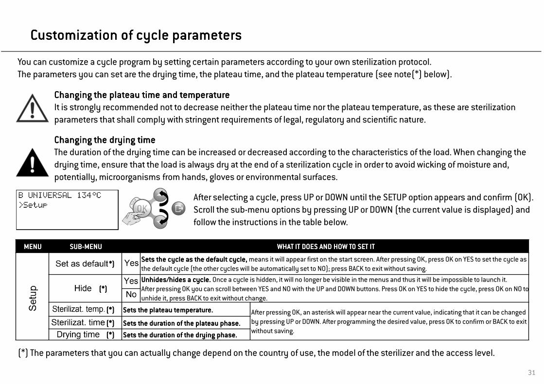
(*)(*)(*)(*)Sets the cycle as the default cycle, Sets the cycle as the default cycle, Sets the cycle as the default cycle, Sets the cycle as the default cycle, means it will appear first on the start screen. After pressing OK, press OK on YES to set the cycle as the default cycle (the other cycles will be automatically set to NO); press BACK to exit without saving.
(*)(*)(*)(*)UnhidesUnhidesUnhidesUnhides/hides a cycle. /hides a cycle. /hides a cycle. /hides a cycle. Once a cycle is hidden, it will no longer be visible in the menus and thus it will be impossible to launch it.After pressing OK you can scroll between YES and NO with the UP and DOWN buttons. Press OK on YES to hide the cycle, press OK on NO to unhide it, press BACK to exit without change.
(*)(*)(*)(*) SetsSetsSetsSets the plateau temperature.the plateau temperature.the plateau temperature.the plateau temperature. After pressing OK, an asterisk will appear near the current value, indicating that it can be changed by pressing UP or DOWN. After programming the desired value, press OK to confirm or BACK to exit without saving.
(*)(*)(*)(*) SetsSetsSetsSets the the the the durationdurationdurationduration ofofofof the plateau the plateau the plateau the plateau phasephasephasephase....
(*)(*)(*)(*) SetsSetsSetsSets thethethethe durationdurationdurationduration ofofofof thethethethe dryingdryingdryingdrying phasephasephasephase....
(*) The parameters that you can actually change depend on the country of use, the model of the sterilizer and the access level.
After selecting a cycle, press UP or DOWN until the SETUP option appears and confirm (OK).Scroll the sub-menu options by pressing UP or DOWN (the current value is displayed) and
follow the instructions in the table below.
You can customize a cycle program by setting certain parameters according to your own sterilization protocol.The parameters you can set are the drying time, the plateau time, and the plateau temperature (see note(*) below).
Changing the plateau time and temperatureChanging the plateau time and temperatureChanging the plateau time and temperatureChanging the plateau time and temperatureIt is strongly recommended not to decrease neither the plateau time nor the plateau temperature, as these are sterilization parameters that shall comply with stringent requirements of legal, regulatory and scientific nature.
Changing the drying timeChanging the drying timeChanging the drying timeChanging the drying timeThe duration of the drying time can be increased or decreased according to the characteristics of the load. When changing thedrying time, ensure that the load is always dry at the end of a sterilization cycle in order to avoid wicking of moisture and, potentially, microorganisms from hands, gloves or environmental surfaces.

32
Cycle in progressCycle in progressCycle in progressCycle in progress
Information displayed on the screen while a cycle is in progressInformation displayed on the screen while a cycle is in progressInformation displayed on the screen while a cycle is in progressInformation displayed on the screen while a cycle is in progress
Selectable optionsSelectable optionsSelectable optionsSelectable options (preceded by the cursor to the left)By pressing UP or DOWN, certain options will be available (e.g., changing the displayed information, aborting the
cycle, viewing messages, etc.).Name of the current cycle Name of the current cycle Name of the current cycle Name of the current cycle phasephasephasephase
(See cycle profile).
First line First line First line First line changing between:- Name of the current cycle;
- Progress bar (if enabled).
Cycle counterCycle counterCycle counterCycle counter
Number of the current cycle.
Current pressure and temperature Current pressure and temperature Current pressure and temperature Current pressure and temperature
of the sterilizer chamber. Cursor near the "Padlock" iconCursor near the "Padlock" iconCursor near the "Padlock" iconCursor near the "Padlock" iconIndicates that the door is securely
locked.
CountdownCountdownCountdownCountdownApproximate residual time until cycle
completion.

33
Cycle in progressCycle in progressCycle in progressCycle in progress
Screen title
Cycle time
Phase time
Heating element temperature
Steam pressure
Temperature in the chamber
Heating element power output
Theoretical temperature
Additional chamber sensor temperature
Mains voltage
Mains frequency
Total water injected
Water conductivity
Legend of the parameters displayed when scrolling the
INFO screen.
INFO screen and menu optionsINFO screen and menu optionsINFO screen and menu optionsINFO screen and menu optionsWhile a cycle is in progress, you can view the main cycle parameters in real time.
On the “cycle in progress” screen, press UP or DOWN until the INFO option appears. Other menu items are also available at this stage.
Then confirm with OK.
The current parameters of the cycle in progress are displayed.Press UP or DOWN to view the complete list of values (see table below).
Press BACK to return to the standard “cycle in progress" screen.

34
Manual stopManual stopManual stopManual stop
Press DOWN until YES appears.
While a cycle is in progress, you can abort it manually at any time.
Press UP or DOWN until the STOP option appears preceded by the cursor, then proceed as shown below:
Confirm STOP (OK)
Confirm (OK) YES
Once a cycle is aborted, a reset phase commences to safely release any steam pressure from the chamber. This may take several minutes. Do not switch off the sterilizer! Wait until the reset phase is completed.
At this stage you can access some menu items by pressing UP or DOWN.
When selecting the INFO option (see picture) you can view the sterilizer parameters in real time (see previous page).
Before the cycle abortion is confirmed, the abortion procedure can be interrupted at any time; press BACK several times until you get to the “cycle in progress” screen and the cycle will go on as originally programmed.

35
Manual stopManual stopManual stopManual stop
When the reset phase is over, press BACK
Press OK to unlock the door as requested in the second line of the screen.(a waiting message appears wile the door is unlocking)
Open the chamber door and remove the load, or repeat the sterilization cycle.
The message “LOAD NOT STERILE” means that the load is not sterile. Do not use items on patients!The message “DRYING INTERRUPTED” means that the load might be wet. Wet items are for immediate use only!
One of the following messages appears:

36
End of a sterilization cycleEnd of a sterilization cycleEnd of a sterilization cycleEnd of a sterilization cycle
When a cycle is successfully finished, the “CYCLE COMPLETED” message appears on the screen and the “Unlock door” option is preceded by the cursor.At this stage you can press DOWN or UP until the INFO option appears; confirm INFO to access cycle parameters for mechanical sterilization monitoring (see previous pages). This is only possible prior to unlocking the chamber door.
If an alarm message appears at the end of the cycle, consult Chapter 8 (Troubleshooting) of the Instructions for Use and, if the problem persists, call for technical service.
Remove the load from the chamber.
WARNING! THE LOAD AND THE STERILIZER ARE HOT!WARNING! THE LOAD AND THE STERILIZER ARE HOT!WARNING! THE LOAD AND THE STERILIZER ARE HOT!WARNING! THE LOAD AND THE STERILIZER ARE HOT!
Use the tray holder (or cassette holder) to remove the load!
Do not touch the chamber, the inner porthole and the internal fittings as long as they are hot.
Confirm (OK) to unlock the door (the cursor near the “padlock” icon disappears).Wait the door to unlock, then open the chamber door.

37
7. Maintenance7. Maintenance7. Maintenance7. Maintenance
Before carrying out any maintenance on the sterilizer, switch the unit OFF and remove the mains cable.
Before accessing the chamber and the connected parts, be sure that the sterilizer is cold.
Maintenance countersMaintenance countersMaintenance countersMaintenance countersThe sterilizer keeps track of the age of consumables by keeping memory of the number of cycles executed since the last replacement.When one counter reaches the maximum, a replacement message appears on the screen and the consumable needs to be replaced; replace the consumable.
Follow the instructions in this chapter when carrying out any maintenance on the sterilizer.
Maintenance programMaintenance programMaintenance programMaintenance programThe maintenance program is outlined in the table on the next page.It includes the replacement of certain wearing parts (consumables) which is imperative to ensure the safe and faultless operation of the sterilizer.

38
Maintenance programMaintenance programMaintenance programMaintenance program
MAINTENANCE PROGRAM TABLEMAINTENANCE PROGRAM TABLEMAINTENANCE PROGRAM TABLEMAINTENANCE PROGRAM TABLE
Frequency (*) # of cycles (*) Operation Consumable Performed by
Monthly 50
Clean the door seal and the chamber face side
SeeAPPENDIX 8
User
Clean the chamber, trays and the rack
Clean the chamber filter
Clean the external sterilizer surfaces
Clean the steam diffuser plate
3 months 400Replace the bacteriological filter
Replace the dust filter
6 months 800 Clean both water tanks
Yearly 800 Replace the door seal
5 years 4000 General check and serviceService technician
- 20000 General check and service
(*) whichever occurs first

39
Monthly or 50Monthly or 50Monthly or 50Monthly or 50----cycle maintenancecycle maintenancecycle maintenancecycle maintenance
Cleaning the door seal and the chamber face sideCleaning the door seal and the chamber face sideCleaning the door seal and the chamber face sideCleaning the door seal and the chamber face sideClean the door seal and the outer edge of the chamber with a non-abrasive cloth moistened with water. If you use a detergent solution, be careful not to get in contact with the plastic body of the front cover.Rinse with clean water.Do not use abrasive products, cutting tools or sharp objects.
Cleaning the chamber and the chamber accessoriesCleaning the chamber and the chamber accessoriesCleaning the chamber and the chamber accessoriesCleaning the chamber and the chamber accessoriesRemove the trays from the chamber.Remove the chamber rack and the steam diffuser plate.
Ensure that the steam diffuser plate is correctly placed and engaged, as this is essential for the sterilization process.
Clean the chamber with a damp sponge and a mild detergent solution paying attention not to bend or damage the temperature probe inside the sterilizer chamber. Rinse with water.Clean the steam diffuser plate, the trays and the tray rack with a damp sponge and a mild detergent solution. Rinse with water.Reposition all pieces of the chamber accessories properly.
The trays, the tray holder and the steam diffuser plate may also be cleaned in a washer disinfector.
40
Monthly or 50Monthly or 50Monthly or 50Monthly or 50----cycle maintenancecycle maintenancecycle maintenancecycle maintenance
6
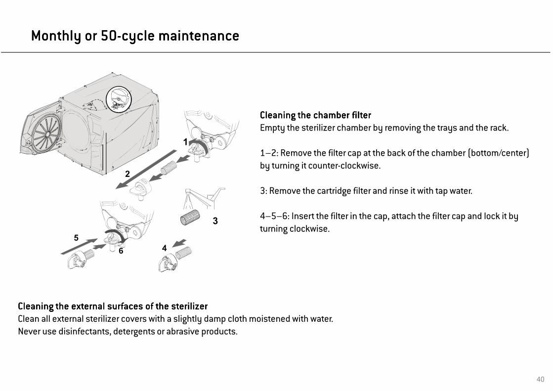
Cleaning the chamber filterCleaning the chamber filterCleaning the chamber filterCleaning the chamber filterEmpty the sterilizer chamber by removing the trays and the rack.
1–2: Remove the filter cap at the back of the chamber (bottom/center) by turning it counter-clockwise.
3: Remove the cartridge filter and rinse it with tap water.
4–5–6: Insert the filter in the cap, attach the filter cap and lock it by turning clockwise.
Cleaning the external surfaces of the sterilizerCleaning the external surfaces of the sterilizerCleaning the external surfaces of the sterilizerCleaning the external surfaces of the sterilizerClean all external sterilizer covers with a slightly damp cloth moistened with water.Never use disinfectants, detergents or abrasive products.

41
3 month or 4003 month or 4003 month or 4003 month or 400----cycle maintenancecycle maintenancecycle maintenancecycle maintenance
Replacing the bacteriological filterReplacing the bacteriological filterReplacing the bacteriological filterReplacing the bacteriological filterOpen the service door.Unscrew the bacteriological filter by hand (counter-clockwise).Screw on the new bacteriological filter (clockwise) and tighten it snug.
Replacing the dust filterReplacing the dust filterReplacing the dust filterReplacing the dust filterPull out the dust filter from underneath the sterilizer.Detach the used filter from the handle.Attach the new filter to the handle.Slide the filter back into its original position.
Remember to reset the counter after replacement (see following pages).
Remember to reset the counter after replacement (see following pages).

42
6 month or 8006 month or 8006 month or 8006 month or 800----cycle maintenancecycle maintenancecycle maintenancecycle maintenance
Do not use abrasive, strong detergents or disinfectants.Use a small non-abrasive brush to clean the areas that are difficult to reach.
Cleaning the water tanksCleaning the water tanksCleaning the water tanksCleaning the water tanksSwitch OFF the sterilizer and disconnect the mains cable.Completely drain both tanks.Leave the drain tube attached to one of the drain quick connectors. Turn the 5 screws of the tank cover a ¼ with the use of a screwdriver (a coin works as well) and lift the cover to gain access to the tanks.ap with your fingers on the rubber membrane to remove any condensate.Remove the rubber membrane; clean and dry it.Clean the internal tank surfaces with a soft sponge and a mild detergent solution, then rinse and dry them. Make sure the drain tube is connected to the tank you are cleaning (left tank – grey colored connector; right tank – blue colored connector) to drain the detergent solution.Only when both tanks are clean, remove the internal filters (A), clean them with tap water and put them back into their position. Reposition the rubber membrane.Close the cover and tighten the 5 tank cover ¼ turn screws .Disconnect the drain tube.
When cleaning the tanks, be careful not to touch the water level sensors. If misplaced or misaligned from their original position, the operation of the sterilizer could be impaired.

43
1 year or 8001 year or 8001 year or 8001 year or 800----cycle maintenancecycle maintenancecycle maintenancecycle maintenance
First: up and down
Then: left and right
Remember to reset the counter after replacement (see following pages).
Replacing the door sealReplacing the door sealReplacing the door sealReplacing the door seal
Fully open the chamber door.
Pull out the used door seal by hand (easy if seal and fingers are dry).
Carefully clean the seal seat and the chamber face side with a cotton swab.
Moisten the new seal with water. This will make placement much easier!
Insert the new seal in the sequence as illustrated in the pictures to the left.
Complete the operation by evenly inserting the seal on the entire circumference; ensure the seal does not stick out (no bumps or deformations)!

44
4000 cycle/5 years general check and service4000 cycle/5 years general check and service4000 cycle/5 years general check and service4000 cycle/5 years general check and service
REPLACEMENT PARTSREPLACEMENT PARTSREPLACEMENT PARTSREPLACEMENT PARTS CLEANINGCLEANINGCLEANINGCLEANING CHECKSCHECKSCHECKSCHECKS
Solenoid valves
Vacuum pump internal parts
Sterilization chamber and external surfaces
Pneumatic connections
Chamber filter Electrical connections
Internal cleaning, with particular care for the condenser fins and the main board
Temperature and pressure calibration
Door locking system
Pressure safety valve
Steam diffuser plate Safety systems
Regular service is imperative to ensure continuous and effective operation of the sterilizer.
It is recommended to carry out a general service every 4000 cycles or five years by an authorized service technician.
The service includes replacement of consumables and other important internal components, a check of the entire unit with special care for the safety systems, and cleaning of areas and components that cannot be accessed by the user.

45
Resetting the maintenance countersResetting the maintenance countersResetting the maintenance countersResetting the maintenance counters
Use the UP, DOWN and OK buttons to browse the menu, choosing the following options in sequence: MENU – DEVICE INFO – SERVICE COUNTERS
Scroll to the concerned consumable by pressing UP or DOWN.The consumable status (number of cycles executed and maximum lifespan of the consumable) is displayed in the third and fourth line of the display.Press OK to select the concerned consumable.
The RESET COUNTER option is displayed: confirm it with OK.
A confirmation request appears: scroll the answer to YES by pressing UP or DOWN and then confirm with OK.
After being reset, the consumable counter shows zero.
After selecting, the concerned consumable appears in the first line.

46
8. Troubleshooting, alarms and messages8. Troubleshooting, alarms and messages8. Troubleshooting, alarms and messages8. Troubleshooting, alarms and messages
If the cursor appears to the left of one or more icons, there is related information pending.All messages can be viewed by means of the MESSAGES sub-menu.
Use the UP, DOWN and OK buttons to browse the menu, choosing the following options in sequence: MENU – MESSAGES.
If there is more than one message pending, you can scroll within messages with UP or DOWN.
The icon that is preceded by the cursor is related to the pending message.
The cursor that precedes the icon disappears as soon as the relevant message has been read and the condition that gave rise to the message has been fixed.
The cursors that precede the message icons are not visible while a cycle is in progress.

47
MessagesMessagesMessagesMessages
ICONICONICONICON MESSAGEMESSAGEMESSAGEMESSAGE DESCRIPTION/ACTION REQUIREDDESCRIPTION/ACTION REQUIREDDESCRIPTION/ACTION REQUIREDDESCRIPTION/ACTION REQUIRED
- The chamber door is locked; no action required.
The water level inside the clean water tank is below the minimum. Fill the clean water tank.
The water level inside the used water tank is at maximum level. Drain used water tank.
Check the external sterilizer water supply. You might have to replace filter cartridges – drain clean water tank and follow instructions for use of water filtration system.
The distilled/demineralized water in the clean water tank is of poor quality. Drain the tank and refill it with water of good quality; refer to APPENDIX 7
Don’t touch the chamber or the load with bare hands: high temperature, risk of burns!
The bacteriological filter needs to be replaced.
The dust filter needs to be replaced.
The door seal needs to be replaced.
The 4000 cycle overhaul needs to be performed. Call for service.
The 20000 cycle overhaul needs to be performed. Call for service.
The CPU board battery needs to be replaced. Call for service.
PC/Logger not detected (disconnected or not powered).
Cycle report printer configured but not detected (disconnected or not powered).
Label printer configured but not detected (disconnected or not powered).
File saving error (check presence and connection of the USB drive).
NOTE: for any message not listed in this table, call service.

48
AlarmsAlarmsAlarmsAlarms
NOTE: for any alarm not listed in this table, call technical service.
AlarmAlarmAlarmAlarm codecodecodecode DESCRIPTIONDESCRIPTIONDESCRIPTIONDESCRIPTION ACTIONACTIONACTIONACTION
E010E010E010E010 Power failure during a cycle Load cannot be considered sterile. Repeat the cycle.
E02xE02xE02xE02x Internal voltage error Switch the sterilizer OFF and ON. If the problem persists call service.
E041E041E041E041 Cycle counter lostSwitch the sterilizer OFF and ON. If the problem persists call service. NOTE: Initiating a sterilization cycle is still possible.
E042E042E042E042 Internal clock errorSet date and time - Switch the sterilizer OFF and ON. If the problem persists call service. NOTE: Initiating a sterilization cycle is still possible.
E060E060E060E060 Internal voltage errorDisconnect optional accessories from 24VDC rear plug - switch the sterilizer OFF and ON. If the problem persists call service.
E080E080E080E080 Internal overheating Check the dust filter and ensure that the sterilizer fan is not blocked.
E090E090E090E090 Internal voltage error Switch the sterilizer OFF and ON. If the problem persists call service.
E100E100E100E100 Phase timeout Check water level in the clean water tank. Reset the thermal overload. If the problem persists call service.
E101E101E101E101 Internal probe error Switch the sterilizer OFF and ON. If the problem persists call service.
E102E102E102E102 Phase timeout Check water level in the clean water tank. Reset the thermal overload. If the problem persists call service.
E107E107E107E107 Overpressure during the pre-vacuum phase If the problem persists call service.
E121E121E121E121 Internal probe error Switch the sterilizer OFF and ON. If the problem persists call service.
E130E130E130E130 Overpressure during the sterilization phaseClean the chamber and the chamber furniture from residuals of detergents, disinfectants and other chemicals.Replace the clean water if it is suspected to be contaminated with chemicals.Ensure all the load is clean rinsed and free from any chemicals before sterilizing.Repeat the cycle. If the problem persists call service.
E131E131E131E131 Temperature fluctuation during the steril. phase
E140E140E140E140 Low pressure during the sterilization phase
E150E150E150E150 Low temperature during the sterilization phase
E160E160E160E160 Over temperature during the sterilization phase
E163E163E163E163 Overpressure detected
E180E180E180E180----E181E181E181E181 Internal probe error. Switch the sterilizer OFF and ON. If the problem persists call service.

49
AlarmsAlarmsAlarmsAlarms
Alarm codeAlarm codeAlarm codeAlarm code DESCRIPTIONDESCRIPTIONDESCRIPTIONDESCRIPTION ACTIONACTIONACTIONACTION
E182E182E182E182 Pressure drop timeoutAfter the process phase the pressure took too long to drop to the atmospheric pressure. If the problem persists call service.
E184E184E184E184 Overtemperature detecded If the problem persists call service.
E215E215E215E215 Fan blocked or faulty electronic control Call service.
E230E230E230E230 Internal probe error Switch the sterilizer OFF and ON. If the problem persists call service.
E231E231E231E231 Overtemperature detecded If the problem persists call service.
E232E232E232E232----E233E233E233E233----E234E234E234E234 Internal probe error Switch the sterilizer OFF and ON. If the problem persists call service.
E240E240E240E240 Heating element error Wait for the chamber to cool down. Reset the thermal overload. If the problem persists call service.
E243E243E243E243 Heating element error Reset the thermal overload. If the problem persists call service.
E310E310E310E310----E320E320E320E320----E33xE33xE33xE33x----E380E380E380E380----E390E390E390E390
Vacuum timeoutCheck the door seal; clean or replace if necessary. Clean the chamber face side. Clean the chamber filter. If the problem persists call service.
E510E510E510E510 Door motor: failure after cycle completion Switch the sterilizer OFF and ON. If the problem persists call service.
E520E520E520E520 Door motor: locking timeout If the problem persists call service.
E570E570E570E570 Door motor: unable to detect the door position Switch the sterilizer OFF and ON. If the problem persists call service.
E580E580E580E580 Door motor: door locked check signal lost If the problem persists call service.
E59xE59xE59xE59x Door motor error Switch the sterilizer OFF and ON. If the problem persists call service.
E950E950E950E950 Internal memory errorSwitch the sterilizer OFF and ON. If the problem persists call service. NOTE: Initiating a sterilization cycle is still possible.
E95xE95xE95xE95x----E96xE96xE96xE96x Internal memory error Switch the sterilizer OFF and ON. If the problem persists call service.
E990E990E990E990 Manual stop The cycle has been aborted by the user. Re-process the load.
NOTE: for any alarm not listed in this table, call technical service.

50
Alarm stopAlarm stopAlarm stopAlarm stop
In case certain important sterilization parameters are not met, the sterilizer will generate an alarm code and abort the cycle automatically. The sterilizer enters into a reset phase; a wait message and an alarm code are displayed on the screen.
Do not switch off the sterilizer: It will take some time (several minutes) to reset the system and reach safe conditions in the sterilizer chamber before it is possible to open the sterilizer door and remove the load.
Alarm endAlarm endAlarm endAlarm endWhen the reset phase is over, you will be asked to press BACK to get to the “Unlock door” option.
Confirm (OK) to unlock the door.While the door is unlocking, a waiting message is displayed.
Water could be present in the chamber when opening the door: prevent spilling (e.g., place a towel under the chamber door).
At this stage select and confirm “Info” to view the sterilizer parameters (see Chapter 6 of this manual).
Open the chamber door and remove the load.
The message “LOAD NOT STERILE” means that the load is not sterile. Do not use items on patients!The message “DRYING INTERRUPTED” means that the load might be wet. Wet items are for immediate use only!

51
Resetting the thermal overloadResetting the thermal overloadResetting the thermal overloadResetting the thermal overload
A safety thermostat is fitted on the sterilizer to prevent overheating of the electric heater.If the safety thermostat opens because of too high temperatures, the alarm E240 or a timeout alarm is generated. If this happens, proceed as follows:- Switch the sterilizer OFF and remove the mains cable.- Wait for the sterilizer to cool down.- Remove the dust filter.- Slide your hand underneath the sterilizer where the dust filter was located and push on the reset button of the thermostat switch (see pictures to the left).-A click sound will indicate that the thermostat switch has been reset.- Insert the dust filter back into its original position.-Connect the mains cable and switch the sterilizer ON.- Wait for the sterilizer to finish the alarm reset phase and follow the instructions on the display.
If the thermostat opens repeatedly, call technical service.

52
TroubleshootingTroubleshootingTroubleshootingTroubleshooting
PROBLEMPROBLEMPROBLEMPROBLEM POSSIBLE CAUSEPOSSIBLE CAUSEPOSSIBLE CAUSEPOSSIBLE CAUSE SOLUTIONSSOLUTIONSSOLUTIONSSOLUTIONS
The sterilizer remains switched OFF.
The main switch or network circuit breaker is OFF Activate the main switch or network circuit breaker (ON).
No voltage at the socket Check the electric circuit.
The mains cable is not properly connected Attach the cord set properly.
Water is leaking at the front of the sterilizer
Leaks through the chamber door seal Clean or replace the door seal. Clean the chamber face side.
Internal leak. Call technical service.
The cycle commences but there is no pressure/temperature rise
The thermal overload switch is open Reset the thermal overload switch (see “Resetting the thermal overload” in this manual).
Electric – electronic fault Call technical service.
At the end of the cycle, there is residual water in the chamber
Sterilizer not properly levelled Properly level the surface the sterilizer is placed on.
Overloaded chamberComply with the maximum load weight limits for each type of load. Always use the chamber rack for trays and cassettes.
Chamber filter clogged Remove and clean the chamber filter.
Load incorrectly placed Follow the recommendations as listed in APPENDIX 2.
Corrosion or spots on instruments
Tap water on instruments when placed in the sterilizer Ensure that instruments are dry before they are placed in the sterilizer.
Use of water of poor quality or water containing chemical substances
Drain both water tanks. Use water of good quality (see APPENDIX 7).
Organic or chemical residues on the instruments Clean, rinse and dry instruments before placing them in the sterilizer (see APPENDIX 2).
Contact between instruments of different materialsEnsure that instruments of different materials do not touch (aluminum, carbon or stainless steel, etc.); place them on different trays or cassettes or pouch them (refer to APPENDIX 2).
Scale deposits on the chamber Clean the chamber and use water of good quality (refer to APPENDIX 7).
Instruments are turning brown or black.
Incorrect temperature selectedSelect a sterilization cycle featuring a lower sterilization temperature. Follow the instructions of the instrument manufacturer.
The cycle report printer does not work
Printer not properly connected or not powered Check the data and the power connection to the printer.
Serial port not configuredIf the printer is connected directly: configure the serial port to “Printer” (see Table 2).If connected via PC/Logger: configure the serial port to “PC/Logger” (see Table 2).
The cycle is in progress and the automatic report printing is enabled
You are trying to print a stored cycle but the printer is busy to print the data of the cycle in progress: the requested printout will be queued.NOTE: The max. queue is 5 cycles. Longer queues will be ignored.
No cycles are stored in the cycle history menu
Power board replaced by serviceThese service steps cause loss of memory.
Serial number re-entered by service

53
TroubleshootingTroubleshootingTroubleshootingTroubleshooting
PROBLEMPROBLEMPROBLEMPROBLEM POSSIBLE CAUSEPOSSIBLE CAUSEPOSSIBLE CAUSEPOSSIBLE CAUSE SOLUTIONSSOLUTIONSSOLUTIONSSOLUTIONS
When starting a cycle, the chamber door locks but re-opens immediately. The “Open the door” message appears.
Door seal not properly placed; seal sticking out Ensure that the door seal is evenly inserted on the entire circumference.
OK button was pressed twice to launch the cycle Try again by pressing OK only once.
Door jammed by external objects or by the load itselfRemove any objects interfering with the chamber door. Check the door does not force against the load or the chamber furniture.
When the sterilizer is connected to an automated water supply system: There is no clean water in the tank, but the automatic water filling does not start.
Water fill system (optional) not installed Install a water fill system.
Water fill system (optional) not connectedConnect the water fill system to the sterilizer (see Appendix 7 for water quality requirements).
Water fill system (optional) not configured Enable the water fill system in the “Configuration” sub-menu (see Chapter 5, Table 2).
When the water fill system attempted to fill the tank, water was temporarily unavailable
Since water tank filling is attempted only once in-between cycle execution, this event inhibits water feeding. Switch the sterilizer OFF and then ON again.Check the external water supply system.Check for water leaks from the sterilizer.
The sterilizer enters into “Sleep mode” immediately after opening the chamber door.
The chamber door has not been opened after the previous cycle had finished and the “Sleep mode delay” has expired
Press any button on the control panel to exit from “Sleep mode”.
At the end of the cycle the display reads “Open the door” but opening the door is impossible.
The chamber is in vacuum due to an internal malfunction
Switch the sterilizer OFF: this will release any internal pressures allowing the chamber door to be opened. Call technical service if the problem persists.
The bacteriological filter is blockedRemove the bacteriological filter to get the pressure released. Replace the filter. Note that bacterilogical filters need to be replaced every 400 cycles.
The sterilization (PROCESS) phase of a sterilization cycle was longer than expected.
The chamber temperature dropped below the minimum threshold and the software performed a successful recovery
Wait for cycle completion. If the problem occurs frequently, call technical service.
Before sending the sterilizer for technical service, remove the mains cable, empty both water tanks and use the original or appropriate packaging.

54
9. Recycling and disposal9. Recycling and disposal9. Recycling and disposal9. Recycling and disposal
LINA MB sterilizers are mainly built from fiber-reinforced polymers, metals and electronic components.
In case of disposal:- separate the various components according to the materials they are made of;- drop the sterilizer with a company that specializes on the recycling of related products;- do not abandon the sterilizer in unsecured places;- always refer to current/applicable laws and rules in the country of use.
The same instructions apply to disposal of all used consumable parts.

55
APPENDIX 1. Technical dataAPPENDIX 1. Technical dataAPPENDIX 1. Technical dataAPPENDIX 1. Technical data
CONFORMITIESCONFORMITIESCONFORMITIESCONFORMITIES
STERILIZER featuring STERILIZER featuring STERILIZER featuring STERILIZER featuring type type type type B sterilization B sterilization B sterilization B sterilization cycles conform with the cycles conform with the cycles conform with the cycles conform with the following following following following standards:standards:standards:standards:93/42/CEE Medical Device Directive (MDD)97/23/CEE Pressure Equipment Directive (PED)2002/96/CEE Waste Electrical and Electronic Equipment (WEEE)EN 13060 Small steam sterilizer
IEC 61010-1Safety requirements for electrical equipment for measurement, control and laboratory use, general requirements
IEC 61010-2-040Safety requirements for electrical equipment for measurement, control and laboratory use; particular requirements for autoclaves using steam for the treatment of medical materials and for laboratory processes.
EN 61326Electrical equipment for measurement, control and laboratory use: EMC requirements.
PRODUCT LABELSPRODUCT LABELSPRODUCT LABELSPRODUCT LABELS
Data plate
Sterilization chamber label Manufacturer label
TECHNICAL DATATECHNICAL DATATECHNICAL DATATECHNICAL DATA
ElectricalElectricalElectricalElectrical supplysupplysupplysupply::::Nominal voltage:Max. power:Max. current:
200 - 240 VAC – 50/60 Hz, single - phase200 - 240 VAC1750 W 8.75 A
SterilizerSterilizerSterilizerSterilizer:Working temperature:Working relative humidity:Storage temperature /rel. humidity:Max altitude:Min. atmospheric pressure:Overall dimensions:Min. space required:Size of the door movement:Weight empty:Max. weight (fully loaded):Max. weight per support area:Max. heat output:Max noise level:
from +5°C to +40°CMax. RH 80% up to 31°C, linearly decreasing to 50% at 40°C-20°C to +60°C/0-90% (with empty tanks)4000m asl0.6 barAW: 450 mm/H: 435 mm/D: 599 mm W: 470 mm/H: 485 mm/D: 650 mmW: 360 mm/H: 410 mm/D: 360 mm38 kg (LINA MB17), 40.5 kg (LINA MB22)50 kg (LINA MB17), 53 kg (LINA MB22)785 kN/mm23000 KJoule/hour63 dB
Pressure safety valve:Safety thermostat
3 bar330°C
SterilizerSterilizerSterilizerSterilizer chamberchamberchamberchamber::::Total volume:
Usable space (for all cycles)
Bacteriological filter:
17 l/Ø 250 mm x D 362 mm (LINA MB17)22 l/Ø 250 mm x D 440 mm (LINA MB22)12 l/W195 mm x H 195 mm x D 297 mm (LINA MB17))15.5 l/W 195 mm x H 195 mm x D 390 mm (LINA MB22)0.3 µm
DistilledDistilledDistilledDistilled orororor demineralizeddemineralizeddemineralizeddemineralized waterwaterwaterwater::::Water quality:Average water consumption:Tank volume:
Fulfilling EN 13060 Ann. C (conductivity < 15μS/cm)0.7 litres/cycle2 x 3.6 liters
ExternalExternalExternalExternal waterwaterwaterwater supplysupplysupplysupply::::Pressure:Flow:
To be compliant with IEC61770min. 2 bar – max. 8.6 barmin. 0.25 – max 0.5 l/min
CommunicationCommunicationCommunicationCommunication withwithwithwith otherotherotherother devicesdevicesdevicesdevices:::: 1 serial port (optional: USB + 2 serial ports)
OtherOtherOtherOther Fully micro-processor controlled, process evaluation systemaccording to EN13060.Programmable sleep-mode.

56
APPENDIX APPENDIX APPENDIX APPENDIX 2. 2. 2. 2. Maintenance of dental handpiecesMaintenance of dental handpiecesMaintenance of dental handpiecesMaintenance of dental handpieces
External disinfectionExternal disinfectionExternal disinfectionExternal disinfectionThis procedure reduces the risk of infection during cleaning and maintenance of the instrument.Wear protective gloves during disinfection.Refer to the instructions of the instrument manufacturer.Avoid using abrasive disinfectants (pH-value 2.5 – 9; no chlorine based disinfectants).We recommend the use of disinfectant wipes rather than spray disinfection.Do not immerse instruments in disinfectants.Residual disinfectants on instruments can cause extensive damage to your instrumentation during sterilization (oxidation, alteration of technical characteristics of seals, rubbers, fiber optics, etc.).
External cleaningExternal cleaningExternal cleaningExternal cleaningThis procedure involves the removal of residues (blood, dentine, etc.) that adhere to critical areas such as spray outlets, light ports, knurling etc.Wear protective gloves during cleaning.Refer to the instructions of the instrument manufacturer.Use a soft, damp brush and take care not to scratch the surface of the light ports.
LubricationLubricationLubricationLubricationOnce the instrument has been disinfected, cleaned and dried (free from residues), it must be lubricated prior toprior toprior toprior to sterilization.Follow manufacturer’s instructions for proper lubrication.
PackagingPackagingPackagingPackagingIn order to preserve sterility, rotating instruments should be wrapped/bagged prior to sterilization. Follow the manufacturer’s packing instructions when using sterilization packaging (also see “Sterilization load preparation” in APPENDIX 2 of this manual).

57
APPENDIX APPENDIX APPENDIX APPENDIX 3. 3. 3. 3. Sterilization load preparationSterilization load preparationSterilization load preparationSterilization load preparation
Cleaning the instrumentsCleaning the instrumentsCleaning the instrumentsCleaning the instrumentsClean all instruments thoroughly prior to sterilization.If possible, clean instruments immediately after use; always follow the instrument manufacturer ‘s instructions.Remove all traces of disinfectants and detergents.Rinse and dry carefully all instruments.Lubricate dental handpieces after cleaning and prior to sterilization in accordance with the manufacturer’s instructions.
Preparing the traysPreparing the traysPreparing the traysPreparing the traysDo not overload the chamber; adhere to the maximum load weight limits (see cycle program table; the available sterilization cycles).Always use the chamber rack to allow adequate steam circulation.Place pouched items on trays with the paper side facing up.Place pouched items on trays with the paper side facing up.Place pouched items on trays with the paper side facing up.Place pouched items on trays with the paper side facing up.Do not overload trays; spread single items on multiple trays.Place cassettes in the vertical position (if possible) to enhance drying.Place empty containers or non-perforated trays upside down to prevent accumulation of water.Items made from different materials (stainless steel, carbon steel, aluminum, etc.) must be placed on separate trays or wrapped/pouched.If the instruments are manufactured from carbon steel, paper should be placed between them and the trays to avoid rusty spots.Sterilize hinged instruments (e.g., forceps, extraction pliers, etc.) in the open position.Wrap items with porous wrapping materials to facilitate steam penetration and drying (e.g. sterilization bags for autoclaves).
The instruments must be carefully rinsed and dried prior to sterilization.The instruments must be carefully rinsed and dried prior to sterilization.The instruments must be carefully rinsed and dried prior to sterilization.The instruments must be carefully rinsed and dried prior to sterilization.Any residual of chemicals (like cleaning and disinfection products), could affect the purity of the steam and consequently the whole sterilization process, and could seriously damage the sterilizer.The manufacturer’s warranty is void in case of damage from chemicals coming from the load or added to it.The manufacturer’s warranty is void in case of damage from chemicals coming from the load or added to it.The manufacturer’s warranty is void in case of damage from chemicals coming from the load or added to it.The manufacturer’s warranty is void in case of damage from chemicals coming from the load or added to it.

58
Loading the chamberLoading the chamberLoading the chamberLoading the chamber
TubesTubesTubesTubesRinse, drain and dry tubes after washing.Place tubes on a tray allowing the ends to remain open. Do not bend tubes.
Wrapped/bagged itemsWrapped/bagged itemsWrapped/bagged itemsWrapped/bagged itemsPlace the bags on trays allowing adequate space in-between bags.Ensure that packs do not touch the sterilizer chamber walls.Place sterilization bags with the paper side facing up.
Paper side up
Space between bags
Before initiating a sterilization cycle, always check that the steam diffuser plate is properly positioned.
Never place the load or the trays directly into the chamber without the chamber rack as this could affect the steam and temperature distribution. The load must always be supported by the chamber rack.
Before touching, ensure the sterilization chamber is cold: risk of burns!
An improper positioning of the steam diffuser plate could result in bad steam quality and could impair the sterilization process, with risk of non sterile load and cross infection.Sterility at the end of the cycle is not guaranteed if the steam diffuser plate was not correctly placed.

59
APPENDIX 4. Bowie and Dick testAPPENDIX 4. Bowie and Dick testAPPENDIX 4. Bowie and Dick testAPPENDIX 4. Bowie and Dick test
DescriptionDescriptionDescriptionDescriptionThe Bowie & Dick (B&D) test device is used to validate the sterilizer performance for textile load sterilization.It is made of several sheets of paper wrapped in a small packet in the middle of which there is a chemical heat-sensitive indicator sheet.
How to carry out the testHow to carry out the testHow to carry out the testHow to carry out the testThe test must be performed in an empty chamber (EN13060) without load but with the standard chamber accessories (chamber rackand trays) mounted.Place the Bowie & Dick test pack in the center of a tray in the lowest rack position.
Use the UP, DOWN and OK buttons to browse the menu, choosing the following options in sequence: TEST CYCLES – B&D/HELIX.Initiate the cycle (see “Running a sterilization cycle”).Once the cycle is finished, remove the test pack from the chamber.Remove the indicator sheet from the center of the test pack and check the change in colour:
TEST PASSEDTEST PASSEDTEST PASSEDTEST PASSEDThe entire surface of the indi-cator sheet has changed colour.
TEST FAILEDTEST FAILEDTEST FAILEDTEST FAILEDCertain areas of the indicator sheet have not changed colour, e.g., the central part has not turned dark due to an air pocket in the center of the test pack.
The test pack will be very hot at the end of the cycle! The test pack will be very hot at the end of the cycle! The test pack will be very hot at the end of the cycle! The test pack will be very hot at the end of the cycle! It is normal that the test pack is wet.Test failure indicates that there was an air pocket present during the cycle due to sterilizer malfunction. If the test fails repeatedly call technical service.Follow local/national guidelines on the frequency of testing.

60
APPENDIX 5. Helix testAPPENDIX 5. Helix testAPPENDIX 5. Helix testAPPENDIX 5. Helix test
DescriptionDescriptionDescriptionDescriptionThe Helix test device is used to validate the sterilizer performance for hollow items.It consists of a 1,500 mm long tube that is open on one side and closed with a capsule on the other side. A chemical indicator strip is placed inside of the capsule.
How to carry out the testHow to carry out the testHow to carry out the testHow to carry out the testThe test must be performed in an empty chamber (EN13060) without load but with the standard chamber accessories (chamber rackand trays) mounted.Place an indicator strip inside the capsule according to the instructions of the test manufacturer.Close the capsule.
Use the UP, DOWN and OK buttons to browse the menu, choosing the following options in sequence: TEST CYCLES – B&D/HELIX.Initiate the cycle (see “Running a sterilization cycle”).Once the cycle is finished, remove the test device from the chamber.Remove the indicator strip from the capsule and check the change in colour:
The indicator strip has turned dark. Part of the chemical indicator strip has not turned dark; e.g. due to residual air inside the capsule.
TEST PASSEDTEST PASSEDTEST PASSEDTEST PASSED TEST FAILEDTEST FAILEDTEST FAILEDTEST FAILED
Test failure indicates that there was an air pocket present during the cycle due to sterilizer malfunction.If the test fails repeatedly call technical service.Follow local/national guidelines on the frequency of testing.

61
APPENDIX 6. Vacuum testAPPENDIX 6. Vacuum testAPPENDIX 6. Vacuum testAPPENDIX 6. Vacuum test
DescriptionDescriptionDescriptionDescriptionThe vacuum test is designed to validate the sterilizer performance in terms of:• Efficiency of the vacuum pump;• Tightness of the pneumatic circuit.
It consists of a vacuum phase, followed by a stabilization period of 5 minutes and a testing period of 10 minutes.During the 10-minute testing period the internal pressure is monitored. The pressure rise must be less than 0.013 bar.
How to carry out the testHow to carry out the testHow to carry out the testHow to carry out the testThe test must be performed when the sterilizer chamber is completely dry and coldsterilizer chamber is completely dry and coldsterilizer chamber is completely dry and coldsterilizer chamber is completely dry and cold as otherwise the test could produce a “false negative” outcome.
Use the UP, DOWN and OK buttons to browse the menu, choosing the following options in sequence: TEST CYCLES – VACUUM TEST.
Initiate the cycle (see “Running a sterilization cycle”).
Once the cycle is finished, you will be able to open the chamber door.A display message will inform if the test passed or failed.
If the test failed, check, clean or replace the door gasket, clean the chamber face side and the chamber filter; repeat the test.If the test fails repeatedly call technical service.Follow local/national guidelines on the frequency of testing.

62
APPENDIX 7. Water qualityAPPENDIX 7. Water qualityAPPENDIX 7. Water qualityAPPENDIX 7. Water quality
The use of water with a conductivity greater than 15µS/cm may affect the sterilization process and damage the sterilizer.The use of water with a conductivity greater than 50µS/cm, or not complying with the specifications in the table above, may strongly affect the sterilization process and seriously damage the sterilizer.The manufacturer’s warranty is void if the sterilizer was used with The manufacturer’s warranty is void if the sterilizer was used with The manufacturer’s warranty is void if the sterilizer was used with The manufacturer’s warranty is void if the sterilizer was used with water containing contaminant or chemical levels water containing contaminant or chemical levels water containing contaminant or chemical levels water containing contaminant or chemical levels exceeding exceeding exceeding exceeding those listed in the table those listed in the table those listed in the table those listed in the table above.above.above.above.
FEED WATER SPECIFICATIONSFEED WATER SPECIFICATIONSFEED WATER SPECIFICATIONSFEED WATER SPECIFICATIONS
Contaminants/minerals/qualitiesContaminants/minerals/qualitiesContaminants/minerals/qualitiesContaminants/minerals/qualities Value/SpecificationValue/SpecificationValue/SpecificationValue/Specification
Evaporate residue < 10 mg/l
Silicon oxide, SiO2 < 1 mg/l
Iron < 0,2 mg/l
Cadmium < 0,005 mg/l
Lead < 0,05 mg/l
Heavy metals (excl. iron, cadmium, lead) < 0,1 mg/l
Chloride < 2 mg/l
Phosphate < 0,5 mg/l
Conductivity (at 20°C) < 15 µs/cm
pH value 5 - 7
Appearance colorless, clean, free from sediment
Hardness < 0,02 mmol/l
Chemical additives NoNoNoNo chemicalschemicalschemicalschemicals orororor additivesadditivesadditivesadditives mustmustmustmust bebebebe addedaddedaddedadded totototo thethethethe waterwaterwaterwater usedusedusedused forforforfor thethethethe steamsteamsteamsteam sterilizationsterilizationsterilizationsterilization processprocessprocessprocess, even if
they are specifically claimed for use in steam generators, or for steam production, or as additives for
sterilization, disinfection, cleaning or corrosion protection.
LINA MB sterilizers use distilled or demineralized water to generate steam for the sterilization process.The table below lists the maximum content of minerals and the specifications for the water used for steam sterilization (see EN13060 APPENDIX C).

APPENDIX 8. Example of cycle data reportAPPENDIX 8. Example of cycle data reportAPPENDIX 8. Example of cycle data reportAPPENDIX 8. Example of cycle data report
63
Sterilizer brandSterilizer model and serial number
Surgery – practice – doctor nameCycle name
Cycle counterProgrammed sterilization temperature
Programmed sterilization timeProgrammed drying timeCycle start date and time
Headers for the table below
Cycle start Pre-heating phase
Pressure and vacuum pulses
Phase of pressure rise to sterilization conditions
Sterilization phase (process) startMin. and max. temperatures
during the sterilization phase (process)Min. and max. pressures
during the sterilization phase (process)Process end conditions
Drying phase startDrying phase end
Chamber venting phasePressure leveling phase
Cycle end conditions
Cycle enddate and time
Cycle outcome
Tracking code for traceability management

64
APPENDIX 9. Accessories and spare partsAPPENDIX 9. Accessories and spare partsAPPENDIX 9. Accessories and spare partsAPPENDIX 9. Accessories and spare parts
Printer model S'Printpart n. 19721108
Permanent drain kitpart n. X051052x
Aluminium trayLINA MB17: part n. F523204xLINA MB22: part n. F523205x
Tray holderpart n. F523001x
Drain tubepart n. S230900x
Mains cablepart n. U38010xx
Dust filterpart n. F364502x
Door sealpart n. F460504x
Funnelpart n. F540903x
Bacteriological filterpart n. W322400x
Wall spacerpart n. F190107x
Safety bracket kitpart n. X051019x
Automatic water feed and drain kitpart n. X051110x
Label printer LisaSafepart n. 19721101 (with bar code reader)part n. 19721102 (without bar code reader)
Multiport (PC/logger)part n. 19721118
Drain tube kit with fittingspart n. A812110X

AccessoriesAccessoriesAccessoriesAccessories
Cycle report printer (Cycle report printer (Cycle report printer (Cycle report printer (S'PrintS'PrintS'PrintS'Print) ) ) ) ---- part n. 19721108part n. 19721108part n. 19721108part n. 19721108S'Print is a compact, reliable and easy-to-use printer that can be connected directly to the serial port located in the rear of the sterilizer, or via the Multiport (optional PC/logger, see next page).S'Print can be easily managed from the sterilizer control panel (See Chapter 5 - Programming) in order to:
- Print cycle data reports (see Appendix 8 “Example of a cycle data report”) at the end of each cycle either in automatic or manual print mode;
- Print a report of any cycle stored in the sterilizer memory.Printouts are very durable and can be stored in the file records for years.
65
Label printer (Label printer (Label printer (Label printer (LisaSafeLisaSafeLisaSafeLisaSafe) ) ) ) ---- part n. 19721101 (with bar code reader), 19721102 (without bar code reader)part n. 19721101 (with bar code reader), 19721102 (without bar code reader)part n. 19721101 (with bar code reader), 19721102 (without bar code reader)part n. 19721101 (with bar code reader), 19721102 (without bar code reader)LisaSafe is a fast label printer that can be connected directly to the serial port located in rear of the sterilizer, or via the Multiport (optional PC/logger, see next page). LisaSafe prints self-adhesive permanent paper labels to be attached to pouches, showing:-either the main information of the cycle and the sterile load (cycle number and type, date, time, expiry date);- or the sterilization lot number.LisaSafe is conceived to be the heart of the traceability system in the dental practice, permitting a safe and easy management of the stock of sterilized tools and instruments.LisaSafe is also compatible with the W&H sterilizers series 300, 500 and 500 Fully Automatic.All the label printer functions can be easily controlled from the sterilizer control panel (See Chapter 5 -Programming) in order to:
- Print a selected number of labels at the end of the cycle, either in automatic or manual print mode;- Print extra labels of the most recent cycle;- Print labels of any cycle stored in the sterilizer memory.
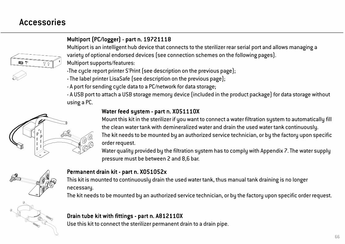
Multiport (PC/logger) Multiport (PC/logger) Multiport (PC/logger) Multiport (PC/logger) ---- part n. 19721118part n. 19721118part n. 19721118part n. 19721118Multiport is an intelligent hub device that connects to the sterilizer rear serial port and allows managing a variety of optional endorsed devices (see connection schemes on the following pages).Multiport supports/features:-The cycle report printer S'Print (see description on the previous page);- The label printer LisaSafe (see description on the previous page);- A port for sending cycle data to a PC/network for data storage;- A USB port to attach a USB storage memory device (included in the product package) for data storage without using a PC.
66
Permanent drain kit Permanent drain kit Permanent drain kit Permanent drain kit ---- part n. X051052xpart n. X051052xpart n. X051052xpart n. X051052xThis kit is mounted to continuously drain the used water tank, thus manual tank draining is no longer necessary. The kit needs to be mounted by an authorized service technician, or by the factory upon specific order request.
AccessoriesAccessoriesAccessoriesAccessories
Water feed system Water feed system Water feed system Water feed system ---- part n. X051110Xpart n. X051110Xpart n. X051110Xpart n. X051110XMount this kit in the sterilizer if you want to connect a water filtration system to automatically fill the clean water tank with demineralized water and drain the used water tank continuously. The kit needs to be mounted by an authorized service technician, or by the factory upon specific order request.Water quality provided by the filtration system has to comply with Appendix 7. The water supply pressure must be between 2 and 8,6 bar.
Drain tube kit with fittings Drain tube kit with fittings Drain tube kit with fittings Drain tube kit with fittings ---- part n. A812110Xpart n. A812110Xpart n. A812110Xpart n. A812110XUse this kit to connect the sterilizer permanent drain to a drain pipe.

67
Accessory connection scheme (data communication)Accessory connection scheme (data communication)Accessory connection scheme (data communication)Accessory connection scheme (data communication)
LisaSafeLisaSafeLisaSafeLisaSafe
S’PrintS’PrintS’PrintS’Print
MultiportMultiportMultiportMultiport
Kit LisaSafeKit LisaSafeKit LisaSafeKit LisaSafe
S’PrintS’PrintS’PrintS’Print
MultiportMultiportMultiportMultiport

68
Accessory connection scheme (water treatment, supply and drain)Accessory connection scheme (water treatment, supply and drain)Accessory connection scheme (water treatment, supply and drain)Accessory connection scheme (water treatment, supply and drain)
External water External water External water External water filtration systemfiltration systemfiltration systemfiltration system
Water feed systemWater feed systemWater feed systemWater feed system
OsmoOsmoOsmoOsmo

69
Accessories and spare partsAccessories and spare partsAccessories and spare partsAccessories and spare parts
190x43x300/375 *
190x43x300/375 *
190x43x300/375 *
205x35x300/375 *
205x35x300/375 *
210x35x300/375 *
190x32x300/375 *
210x32x300/375 *
210x32x300/375 *
190x32x300/375 *
190x70x300/375 *
190x70x300/375 *
Standard chamber rack for 3 cassettes (*)LINA MB17: part n. F523008xLINA MB22: part n. F523009x
Standard chamber rack for 3 USA size cassettes (*) LINA MB17: part n. F523020xLINA MB22: part n. F523021x
Standard chamber rack for 4 cassettes (*)LINA MB17: part n. F523012xLINA MB22: part n. F523015x
Standard chamber rack for 2 implant cassettes (*) LINA MB17: part n. F523016xLINA MB22: part n. F523017x
(*) All racks shown in this page, if rotated
90°, accept 5 standard aluminium trays.

70
ConsumablesConsumablesConsumablesConsumables
400400400400----800 cycle800 cycle800 cycle800 cycle consumable kit consumable kit consumable kit consumable kit ---- part n. X050315xpart n. X050315xpart n. X050315xpart n. X050315xThis kit consists in a stock of consumables suitable to run 800 cycles.It includes:- 1 door seal;- 2 air filters;- 2 dust filters with handle.
2 x
2 x
Dust filter Dust filter Dust filter Dust filter ---- part n. F364502xpart n. F364502xpart n. F364502xpart n. F364502xReplace every 400 cycles
Door seal Door seal Door seal Door seal ---- part n. F460504xpart n. F460504xpart n. F460504xpart n. F460504xReplace every 800 cycles
Bacteriological filter Bacteriological filter Bacteriological filter Bacteriological filter ---- part n. W322400xpart n. W322400xpart n. W322400xpart n. W322400xReplace every 400 cycles
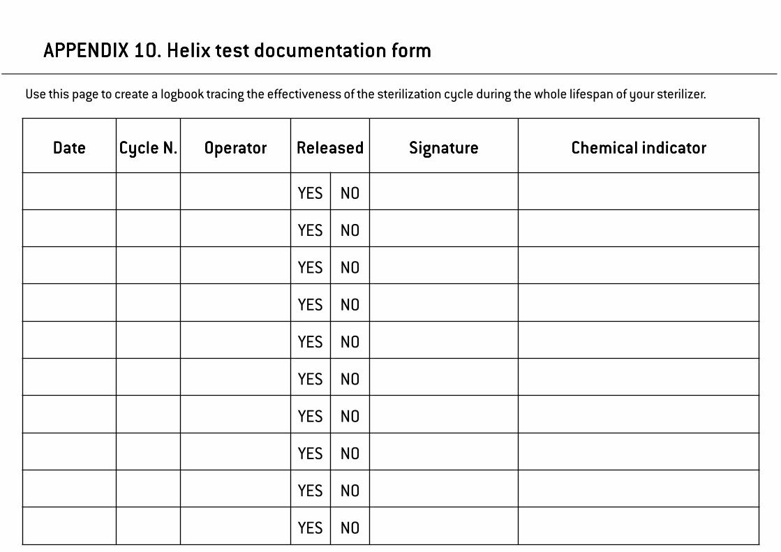
APPENDIX 10. Helix test documentation formAPPENDIX 10. Helix test documentation formAPPENDIX 10. Helix test documentation formAPPENDIX 10. Helix test documentation form
DateDateDateDate Cycle N.Cycle N.Cycle N.Cycle N. OperatorOperatorOperatorOperator ReleasedReleasedReleasedReleased SignatureSignatureSignatureSignature Chemical indicatorChemical indicatorChemical indicatorChemical indicator
YES NO
YES NO
YES NO
YES NO
YES NO
YES NO
YES NO
YES NO
YES NO
YES NO
Use this page to create a logbook tracing the effectiveness of the sterilization cycle during the whole lifespan of your sterilizer.

YES NO
YES NO
YES NO
YES NO
YES NO
YES NO
YES NO
YES NO
YES NO
YES NO
YES NO
YES NO
YES NO
YES NO

NotesNotesNotesNotes


AuthorizedAuthorizedAuthorizedAuthorized W&H service W&H service W&H service W&H service partnerspartnerspartnerspartners
Find your nearest W&H service partner at http://wh.comSimply go to the menu option »Service« for full details. Alternatively please contact:
W&H UK LIMITEDW&H UK LIMITEDW&H UK LIMITEDW&H UK LIMITED, 6 Stroud Wood Business Centre, Park Street, St.Albans, Herts AL2 2NJt +44 1727 874990 f +44 1727 874628 [email protected]
AAAA----DEC AUSTRALIA DEC AUSTRALIA DEC AUSTRALIA DEC AUSTRALIA CO.INCCO.INCCO.INCCO.INC., Unit 8, 5-9 Ricketty Street, Mascot NSW 2020,t +61 2 83324000 f +61 2 83324099 [email protected]
IvoclarIvoclarIvoclarIvoclar VivadenVivadenVivadenVivadent NZ, P.O.Box 5243, Wellesley Street, 12 Omega Street, Auckland,t +64 9 914 9999 f +64 9 914 9958 [email protected]
Iso 13485,93/42 EEC – Annex II
LINA MB 201 11 ENG Rev. 3.1Subject to alterations
ManufacturerManufacturerManufacturerManufacturer
W&HW&HW&HW&H Sterilization S.r.l.Italy, I-24060 Brusaporto (Bg), via Bolgara, 2
t +39/035/66 63 000 f +39/035/50 96 988wh.comwh.comwh.comwh.com