instructions for use sol laser for use sol laser. directions for use ... directions for use | sol...
TRANSCRIPT

INSTRUCTIONS FOR USE
SOL LASER
DIRECTIONS FOR USE | SOL LASER | DENMAT 800.445.0345 | DENMAT.COM
TABLE OF CONTENTS
SECTION PAGEA. INTRODUCTION 2B. WARNINGS AND PRECAUTIONS 2 Emergency Termination of Laser Emissions C. INDICATIONS FOR USE 2-3D. FACILITY AND ENVIRONMENTAL CONSIDERATIONS 3 Power requirements Heating and Ventilation Lighting Combustible Chemicals and Gases Plume Evacuation Operatory Access during SOL Laser Use E. GENERAL SAFETY 4-5 General Safety Considerations Marketing Requirements Regarding Medical Device Safety (USA) Statutory Licensure for Dental Laser Use OSHA Provisions CSA Provisions Eye and Skin Protection Table 1: NOHD (inches/cm) Emergency Shutdown Options F. INSTALLATION AND SETUP 5-7 Instructions on Unpacking & Customer Service Assistance Shipping Container Information Contents of SOL Laser Shipping Container Laser Hand Piece and Fiber Fiber Wrap Key Switch AC/DC Power Supply Connector Power On/Off Switch Foot Switch Connector Remote Interlock Connector G. QUICK START INSTRUCTIONS 7 SOL Quick Start Instructions
SECTION PAGE H. CONTROLS, OPERATION & USE 7-9 SOLSmart Presets SOL Default Mode When the System is Turned On SOL Presets Ready (SOL Activation) Pulse Mode Beeping Volume Aiming Beam Emergency Stop Remote Door Interlock Battery Power Operating Modes Continuous Wave Mode Tissue Response to Laser Energy Installing and Replacing Single-Use Fiber Optic Tips Initiating the Fiber Cleaning Instructions I. RECOMMENDATIONS FOR USE 10 Contraindications Hard Tissue Procedures Calibration Single Use Tips For Infection Control Checking Fiber Continuity Test Firing the SOL Diode Laser Using the SOL Diode Laser J. DENMAT HOLDINGS, LLC SYSTEM SPECIFICATION 11 Complies with Hand Piece Fiber Optic Tips Accessories K. SOL LASER SPECIFICATIONS 12 No Visible Light or Diffuse Light Transmitted By The Aiming Beam Replacing The Main Fiber All Other Conditions Send returns to L. SOL SERVICE & TROUBLESHOOTING 12-14 No Visible Light – Aiming Beam Replacing the Battery Replacing the Fiber Optic Handpiece All Other Conditions Returns

DIRECTIONS FOR USE | SOL LASER | DENMAT 800.445.0345 | DENMAT.COM
1 CUSTOM Programmable favorite setting. Default CW 1.5 Watts2 DEBRIDE Programmable favorite setting for debridement. Default preset CW 0.4 Watts3 PERIO Programmable favorite setting for the treatment of apthous ulcers and periodontal pockets. Default preset Pulse 1.5 Watts4 CUT Programmable favorite setting for fast cutting. Default preset CW 1.2 Watts5 EMERGENCY STOP Turns active laser output OFF6 BATTERY Charge level indicator (Green, Amber, Red) fl ashes when battery is charging7 DISPLAY Laser power level indicator8 UP Adjusts laser power up by 0.1 watts9 DOWN Adjusts laser power down by 0.1 watts10 READY with LED Indicator – toggles between Standby and Laser Ready Modes11 PULSE Mode with illumination. Toggles between CW and Pulse modes NOTE: system defaults to Continuous Watt mode (not illuminated)12 AUDIO Mutes audio. Toggles between audio On/Off 13 AIMING BEAM Adjusts blue aiming beam brightness up and down
NOTE: Preset labels are not intended to imply diagnosis or treatment of oral disease.
1
2
3
4
5
6
7
8
9
10
11
12
13
FIGURE 1.0 PANEL BUTTONS
1

DIRECTIONS FOR USE | SOL LASER | DENMAT 800.445.0345 | DENMAT.COM
� INTRODUCTION
The SOL Laser unit is a dental soft-tissue laser surgical/debridement device. The SOL Laser may be used for a variety of soft-tissue, gingival modifi cation, and sulculartherapy procedures.
Safety is paramount when using any energy-based surgical instrument and your offi ce should implement a safety program for the SOL Laser. If your offi ce does not already have a safety offi cer, one should be appointed to be responsible for understanding proper use, safe operation, and maintenance of the SOL Laser system. Their duties should include training offi ce personnel in all aspects of system safety and management of the SOL Laser and all accessories.
MANUFACTURER’S LASER IDENTIFICATION, OUTPUT AND STANDARDS LABEL
The SOL Laser carries the Manufacturer’s identifi cation label affi xed to the bottom panel of the Control Module.
� WARNINGS & CAUTIONS
EMERGENCY TERMINATION OF LASER EMISSIONS
The SOL Laser has been designed with several methods to terminate emission of laser energy in emergency situations. These methods include an emergency shutoff switch, a key switch and a power switch.
� INDICATIONS FOR USE
The SOL Laser is intended for use by dental professionals in the treatment of dental patients for a variety of oral soft tissue procedures.
The SOL Laser is not intended for hard tissue procedures.
The SOL Laser is indicated for use in dental intraoral soft tissue general, oral maxilla-facial and cosmetive surgery including ablating, incising, excising, vaporizing and coagulation of soft tissues using a fi ber optic delivery system.
2
� Attention, Consult Accompanying Documents
Visible and Invisible Laser Radiation – Avoid eye or skin exposure to direct or scattered radiation
CLASS 4 Laser Product
Caution: US Federal Law restricts the use of this device to use by or on the order of a dentist
Caution: Use of controls or adjustments, or performance of procedures other than those specifi ed herein may result in hazardous radiation exposure.
Warning: Laser Safety Eye Protection MUST BE WORN by the Operator, Patient, Assistant, and anyone present when the laser is activated. Eye Protection must conform to Specifi cation DIN EN207 Annex II of the Directive 89/686/EEC with optical density in 800nm-818nm of OD 4+ such as NoIR Laser Company fi lter model DII
Warning: Do not use in the presence of combustible or combustion supporting gases
Warning: Do not use in the presence of supplemental therapeutic oxygen supplies
Warning: Always test activate the device outside the mouth before using on a patient.
Above Warning is affi xed to front panel of SOL.
Laser aperture warning label affi xed to system hand-piece cradle.
Symbol for: Laser aperture at the end of the handpiece.
MODEL: ASSY SOL LASER
ITEM #: 033989100
LOT #:
MANUFACTURE DATE: MANUFACTURED BY: DENMAT HOLDINGS, LLC LOMPOC, CA 93436 USA
LASER CLASSIFICATION (PER IEC/EN 60825-1:2007): Class 4
MAXIMUM LASER OUTPUT: 3W CW; 5W P
FREQUENCY IN PULSED MODE: Fixed, 10Hz
PULSE DURATION: 0.05 seconds
WORKING BEAM WAVELENGTH: 808 nm (+5 nm)
AIMING BEAM WAVELENGTH: 405 nm (+10 nm) CW
POWER INPUT: 30 Watts + 12 VDC supplied from 100-240 VAC 50-60 Hz Model FW7362M/12
COMPLIES WITH IEC 60601-1, IEC 60601-2-22; IEC/EN 60825-1:2007; IEC 60601-1-2, CLASS B PER EN 60601-1-2 AS WELL AS TO US FEDERAL REGULATIONS FOR LASER PERFORMANCE STANDARDS SET OUT IN 21CFR 1040.10 AND 1040.11 EXCEPT FOR DEVIATIONS PURSUANT TO LASER NOTICE 50 DATED JULY 26, 2001.
001374700 02/13

DIRECTIONS FOR USE | SOL LASER | DENMAT 800.445.0345 | DENMAT.COM
INDICATIONS INCLUDE:
• Excision and incision biopsies
• Hemostatic assistance
• Treatment of aphthous ulcers
• Gingival incision and excision
• Gingivectomy
• Gingivoplasty
• Gingival troughing
• Gingival recontouring
• Tissue retraction for impressions
• Oral papillectomy
• Sulcular debridement
• Sulcular tissue removal
• Removal of granulation tissue
• Frenectomy
• Frenotomy
• Abscess incision and draining and excision
• Operculectomy
• Removal of fibromas
• Soft tissue crown lengthening
In addition to receiving proper training in the use of dental lasers, users should be familiar and experienced with these procedures using electrosurgical devices or traditional instruments before performing them on patients with the SOL Laser. Non-experienced users should seek appropriate training guidance before attempting clinical treatments with the SOL Laser system.
� FACILITY & ENVIRONMENTAL CONSIDERATIONS
In order to insure the safe use of the SOL Laser in your facility, please check to make sure that the proposed location is compatible with the specifi cations listed below.
POWER REQUIREMENTS
External AC/DC Power Supply:Input Power - 110 – 120 VAC @ 60 Hz 700mA; 220-240 V AC @ 50Hz 350mAOutput Power – 30W + 12 VDC at 2.5A maximum
HEATING AND VENTILATION
The optimal temperature range of 20º - 30ºC (68º - 86º F). Avoid storing or transporting the lasers in temperatures below 0º Celsius (32º F).
COMBUSTIBLE CHEMICALS AND GASES
All gases that are combustible or support combustion and are used in the operatory area where the SOL Laser is being operated must be turned off during the procedure. Cleaning supplies or other fl ammable chemical compounds should be stored in an area away from the surgical site in order to avoid possible combustion. Do not use in the presence of supplemental therapeutic oxygen supplies for patients with respiratory or related diseases.
PLUME EVACUATION
Plume evacuation should be addressed when vaporizing tissues. A high volume vacuum system should be used and 0.1 micron or less high fi ltration masks that are suitable for virus and bacterial control should be worn by clinicians.
OPERATORY ACCESS DURING SOL LASER USE
Access to the treatment area should be restricted while the lasers are in use. A sign indicating “LASER IN USE” should be placed in a designated area adjacent to the treatment area entry location.
3
DIRECTIONS FOR USE | SOL LASER | DENMAT 800.445.0345 | DENMAT.COM
� GENERAL SAFETY WITH THE SOL LASER
GENERAL SAFETY CONSIDERATIONS
Safe use of the SOL Laser is the responsibility of the entire dental team including the doctor, any system operators and the dental offi ce safety offi cer.
MARKETING REQUIREMENTS REGARDING MEDICAL DEVICE SAFETY (USA)
The United States Food and Drug Administration (FDA) has control over the sale and use of the all medical devices including the SOL Laser. Manufacturers of products subject to performance standards under the Federal Food, Drug, and Cosmetic Act, Chapter V, Subchapter C - Electronic Product Radiation Controlare required to certify compliance with the regulations and furnish various reports to the Center for Devices and Radiological Health (CDRH). For manufacturers of medical lasers (such as the SOL Lasersystem), additional review by the FDA of the safety and effectiveness of the device is required. Companies who intend to market a medical laser or equivalent device must receive authorization from the FDA before the device is permitted into commercial distribution. The premarket notifi cation (510(k)) process used for the SOL Laser system is applicable for devices that are documented to be substantially equivalent to existing legally marketed Class II devices.
STATUTORY LICENSURE FOR DENTAL LASER USE
Usually, states or provinces do not have a specifi c licensure requirement for use of surgical laser devices by dentists. Many states do, however, require Hygienists who will be using lasers to attend licensure training that includes both a lecture and hands-on experience. The license applicants are then required to pass a profi ciency test for certifi cation prior to using lasers. These courses are usually taught by members of the Academy of Laser Dentistry who possess instructor credentials. Such training would be appropriate for use of the SOL Laser system.
OSHA PROVISIONS
Worker safety is the responsibility of the employer and is regulated by OSHA (Occupational Safety and Health Administration), a division of the U.S. Department of Labor.
OSHA recognizes ANSI standard Z136.1 as a source for analyzing safety with respect to medical lasers. For more information see OSHA Technical Manual (TED1-0.15A) Section III, Chapter 6, 1999. DenMat recommends implementation of a safety programfor the safety of your patients and offi ce staff in connection with the use of the SOL Laser. DenMat also recommends checking and complying with applicable state and provincial safety and health organization requirements.
CSA PROVISIONS
This device is to be installed and operated according to the Canadian Standards Association CAN/CSA-Z386-08 provision for the safe use of the entire laser apparatus. This standard provides guidance for the Health Care Laser System (HCLS), and is intended for use by all personnel associated with the installation, operation, calibration and maintenance and service of the HCLS. This standard includes engineering, procedural and administrative con-trols, and laser safety training necessary for the safety of patients and health care professionals.
Electromagnetic Environment Guidance(Class B (CISPR 11:2009), Group 1 per IEC 60601-1-2, sub-clause 6.8.3.201)
The SOL Laser uses RF Energy only for its internal function. Therefore, its RF emissions are very low and are not likely to cause any interference in nearby electric equipment.
Floors should be wood, concrete, or ceramic tile. If fl oors are covered in synthetic material, the relative humidity should be at least 30%
Mains power quality should be that of a typical commer-cial or hospital environment. The SOL Laser does not require continued operation during power mains inter-ruptions, merely it is recommended that the SOL Laser should be powered from an uninterruptible power supply (UPS) or its battery.
Power Frequency Magnetic Fields should be at levels characteristic of a typical location in a typical commercial or hospital environment.
4

DIRECTIONS FOR USE | SOL LASER | DENMAT 800.445.0345 | DENMAT.COM
EYE AND SKIN PROTECTION
While the SOL Laser is in use, doctors, system operators, auxiliary staff, patients, and anyone in the operatory must wear the appropriate safety eyewear that has been designed for use with the 800-plus nm wavelengths associated with lasers. Eye protection must conform to Specifi cation DIN EN207 Annex II of the Directive 89/686/EEC with optical density of OD+4 for the wavelength range of 800nm-818nm such as NoIR Laser Company fi lter model DI1.
Nominal Ocular Hazard Distance (NOHD) is the distance from the source of laser emission to the point where it no longer exceeds its Maximum Permissible Exposure (MPE – highest level of laser radiation to which a person may be exposed without hazardous effects or adverse biological changes in the eyes or skin). The Nominal Hazard Zone (NHZ) is the space within which the level of direct, refl ected, or scattered radiation during normal operation exceeds the appropriate MPEs. The outer limit of the NHZ is equal to the NOHD. The NOHD for persons wearing recommended safety glasses is shown in Table 1 below.
TABLE 1: NOHD (INCHES/CM)
Radiation Source
MPE mW/cm2
Divergence Angle
Without Eye Protection
With RecommendedEye Protection
Fiber Optic Tip (direct)
1.66 9° (+/- 1°) 155/393.7 1.55/3.94
Reflected from Tissue
1.66 n/a 0.25/0.63 0.0025/0.0063
Never point the SOL Laser tip directly at the face, eyes or skin of anyone while emitting energy.
EMERGENCY SHUTDOWN OPTIONS:
Perform any of these actions to terminate laser emis-sions in the event of a real or perceived emergency:
• Depress the emergency “STOP” button (Fig. 1.1 Item 11)• Remove your foot from the foot switch• Press the “Ready” button (Fig. 1.0 Item 1)• Turn the key counterclockwise to the “OFF” position• Switch the power switch to the “OFF” position• Remote interlock open circuit deactivates laser
� INSTALLATION AND SETUP
INSTRUCTIONS ON UNPACKING & CUSTOMER SERVICE ASSISTANCE
A DenMat customer service representative or dealer can provide assistance when you are ready to remove the SOL Laser from its shipping container. Please do not attempt to unpack the SOL Laser and install or setup the unit without reading this manual fi rst. If you are unsure about any aspect of the assembly, call your DenMat customer service representative or dealer for assistance.
SHIPPING CONTAINER INFORMATION
The shipping container you received with your SOL Laser was specially designed to safely transport the laser. In the unlikely event that you need to return the laser for service or repair, please retain the original shipping container.
CONTENTS OF SOL LASER SHIPPING CONTAINER:The contents of the shipping container should include the following:
• SOL Diode Laser System with Hand Piece and Optical Fiber
• SOL Foot Switch
• AC/DC Power Converter
• Laser Operating Key
• Fiber Optic Tips, 400 Micron/5 pc
• Single-use Barrier Sleeves for Handpiece 25 pc
• Protective Glasses 3 pc
• Safety Sign
• SOL Laser Instructions
• Warranty Information
• Extended Warranty Offer
• Online Training Offer
• Battery Charging Notice
Each of the items listed above should be inspected and the instructions followed. Use of any cables or accessories not supplied with the system, or by DenMat, may damage the system and will void the warranty.
5

DIRECTIONS FOR USE | SOL LASER | DENMAT 800.445.0345 | DENMAT.COM
LASER HAND PIECE AND FIBER
The detachable hand piece and fi ber are installed and ready for use at the time of shipment. Uncoil the fi ber and install a SOL procedure tip into the hand piece. Proper use of the system tips and fi ber replacement is explained later in this manual.
FIBER WRAP
A fi ber wrap is provided to protect and store the system fi ber when not in use. Gently extend the fi ber by unwrapping clockwise and return in the counterclockwise direction. TO AVOID DAMAGE TO THE FIBER, do not bend at sharp angles or in a radius smaller than the internal diameter of the fi ber wrap.
BACK PANEL (FIG. 4)
KEY SWITCH (FIG. 4, ITEM 1)
A removable key switch is provided as a safety feature to prevent the unauthorized operation of the laser. It is the responsibility of the laser safety offi cer to maintain control of the key switch and store it in a secure location when the laser is not in use. The key switch must be turned clockwise to the ON position to power the system controls and activate the laser.
AC/DC POWER SUPPLY CONNECTOR (FIG. 4, ITEM 2)
USE MODEL FW7362M/12 ONLY. An external power supply is provided for charging the system battery and an alternate laser power source. During initial setup use the AC/DC power supply for up to four hours to fully charge the battery. Note the Battery Charge Level indicator (Fig 1, Item 6) on the system control panel, fl ashes to confi rm that the power supply is connected and the battery is charging. NOTE: battery does not charge when the system is in the Ready Mode or during laser activation so Charge Indicator does not fl ash. Plug the power supply into an AC outlet and connect to the corresponding connector on the rear of the system. Only use the SOL Power Supply. Others may damage the system.
POWER ON/OFF SWITCH (FIG. 4, ITEM 3)
The power switch is located on the rear of the system and must be in the ON position for the laser to be operated. Turn the power switch to the OFF position when the laser is not in use.
FOOT SWITCH CONNECTOR (FIG. 4, ITEM 4)
The foot switch is used to activate the laser. Install the plug on the foot switch cable to the corresponding connector on the rear of the system.
PORT FOR FUTURE EXPANSION. DO NOT USE (FIG. 4, ITEM 5)
6
FIG. 2
FIG. 4
FIG 3
�
�
�
NOTE: Avoid Exposure–Laser Radiation is emitted from this aperture.
DIRECTIONS FOR USE | SOL LASER | DENMAT 800.445.0345 | DENMAT.COM
REMOTE INTERLOCK CONNECTOR (FIG. 4, ITEM 6)
The remote interlock is used to turn the laser OFF when the door into the room is opened. Remote interlock operation requires a Door Interlock Switch (not included) to be purchased from a local electronics store. This function is explained fully under Remote Door Interlock.
� QUICK START INSTRUCTIONS
SOL QUICK START INSTRUCTIONSDuring initial setup use the AC/DC power supply for up to four hours to fully charge the battery. Plug the power supply into an AC outlet and connect to the corresponding connector on the rear of the system.1. Plug the foot switch into the connector on the rear of the system.
2. Insert the key switch and turn to the ON position.
3. Turn the power switch to the ON position.
4. System powers up to default Standby Mode 0.8 Watt CW laser setting
5. Option: Adjust Power using Up and Down Arrow keys
6. Option: Enter Pulse Mode by pressing Pulse key
7. Option: Select one of four system presets with the corresponding key
8. Option: Adjust the preset as described in 5 and 6 above
9. Press Ready and note audio and visual indicator confirmations
10. Use the foot switch to activate the laser
� CONTROLS, OPERATION & USE
SOLSMART PRESETS (REFERENCE FIG. 1, ITEM 2-5)
SOL is delivered with fi ve laser output settings programmed into the Default Mode when the system is turned ON and Four Preset Procedure Keys; Cut, Sterilize, Periodontal and Custom. These settings are typical for the corresponding procedures with a diode laser. All fi ve can be reprogrammed with your favorite CW output from .10 to 3.0 watts in .10 watt increments or Pulse output from .10 to 5.0 watts in .10 watt increments. The Default Mode when the system is turned ON provides the fastest way to start lasing. After turning the system ON use the default power setting, or adjust, press READY and start lasing. SOL is smart and remembers the last mode (CW or Pulse) and power setting so the next time the system is powered up it returns to your most commonly used or Favorite Setting.
SOL DEFAULT MODE WHEN THE SYSTEM IS TURNED ON
When the system power and key switches are placed to the ON position SOL system controls default to the factory preset Standby Mode 0.8 Watt CW laser setting. If the laser settings are changed the SOL will “remember” those settings upon exiting and they will become the default for the next session until changed again. Each subsequent change in settings becomes the new default. Adjust the laser CW power Up/Down using the Up or Down arrow keys select the Pulse Mode and adjust laser power Up/Down or enter one of four system presets to begin lasing. Press the Ready key to enter the Ready Mode. Press the Foot Switch to activate the laser. Return to the original default, or any other setting, by entering those settings.
SOL PRESETS
See Fig 1, 1.2-1.5
The laser power and output modes, CW and Pulse, for four typical diode laser procedures are loaded into four button selections labeled Cut, Sterile, Perio and Custom. Default settings are as follows:
PRESET POWER DELIVERY MODECut 1.2 Watts CWDebride 0.4 Watts CWPerio 1.5 Watts PulseCustom 1.5 Watts CW
Press any key to select that preset. When the preset is selected the laser power setting, (in watts), is displayed and the Pulse Mode illumination is ON if Pulse has been programmed for that preset. The laser power can be adjusted with the Up and Down Arrow keys. Pulse and CW can be selected by pressing the Pulse On/Pulse Off key. When the system is in the Pulse Mode the Pulse Icon (1.10) next to the key illuminates alerting the operator that the Pulse Mode is active. Changes to the laser output and CW/Pulse modes can be saved as a new preset by pressing and holding down the key for 3 seconds. If new settings are not saved (programmed) into the preset by holding the key for 3 seconds the original default settings will be retained upon exiting.
7
DIRECTIONS FOR USE | SOL LASER | DENMAT 800.445.0345 | DENMAT.COM
READY (SOL ACTIVATION) SEE FIG. 1
The system powers up in the Standby Mode and returns to Standby each time any key is pressed except READY. The laser cannot be activated in the Standby mode. The READY key, in either the CW or Pulse modes, prepares the system for laser activation. When the READY key is pressed there is an audio alert, unless audio is muted (see audio function), and the Ready indicator LED illuminates Green. The blue aiming beam is visible at the end of the tip. The system is ready for laser activation. When the system is in READY status pressing any key, other than the foot switch, will return the system to the Standby Mode. When the foot switch is pressed in the Ready Mode the Ready Indicator LED fl ashes to provide a visual indication that the laser working beam is On.
PULSE MODE
The system Default Mode and Presets (except Perio) are programmed for CW laser delivery. The CW setting can be changed to Pulse for the Default Mode and Presets by pressing the Pulse key. When the Pulse key is pressed the Pulse Icon next to the key illuminates alerting the operator that the Pulse Mode is active. If the laser delivery is changed from CW to Pulse and saved as the Default Mode or a Preset the icon will illuminate each time that mode is used (until it is changed back to CW). SOL pulse is 10Hz 50% Duty Cycle.
AUDIO ON/OFF
The Audio key toggles the system sound On and Off.
AIMING BEAM
The brightness of the blue aiming beam is preset. It can be controlled by pressing the brightness key. Each time the key is pressed the brightness is increased and the selected level is displayed; A0 through A5. .
EMERGENCY STOP
SOL can be immediately deactivated in any mode, at any power setting by pressing the STOP key. To reset the system, press and hold the STOP key for 5 seconds.
REMOTE DOOR INTERLOCK (DOOR INTERLOCK SWITCH IS NOT INCLUDED)
The SOL diode laser provides a remote interlock feature (pg. 6 Figure 4 item 6) that enables a clinician to establish a laser treatment room with a remote interlock connector/
switch on the entrance door that is electronically wired to the system. When the door to the room is opened the connector/switch provides an electrically open circuit that deactivates laser emissions. The door must be closed with connector/switch providing an electrically closed circuit, with a manual reset by entering the Ready Mode, required to resume laser activation.
To use the remote interlock feature, an interlock connector/switch, cable and connector can be purchased from a local electronics store. Contact your Den-Mat account representative for an assembly drawing a list of parts required to use this feature.
BATTERY POWER
The Battery Charge Indicator changes color to represent the battery capacity.
Green – 100% to 40%Amber – Less than 40%Red – Less than 20%
The battery should be recharged when the indicator turns amber. A long procedure should not be started when the indicator is red unless the external power supply is installed.
NOTE: Charge Indicator fl ashes when the external power supply is connected and the battery is charging.
Battery does not charge when the system is in the Ready Mode or during laser activation so Charge Indicator does not fl ash.
OPERATING MODES
SOL will deliver energy in either continuous wave (CW) or Pulsed (P) “temporal emission mode” (time related mode). Selection of the appropriate mode will allow the operator to optimize control of target tissue temperatures and the effi ciency of energy delivered. The pulse duration (0.05 seconds) and the number of pulses per second (10) is fi xed and not adjustable. Therefore, the operator will need to adjust only the laser power and mode.
CONTINUOUS WAVE MODE
The CW mode is generally the fastest way to ablate tissues but heat can build up and cause collateral damage to adjacent tissues. Cool the tissues being treated by using periodic blasts of air from a triplex syringe and highspeed suction. You may also use water to cool in areas where there is prolonged laser exposure. Avoid using the air
8
DIRECTIONS FOR USE | SOL LASER | DENMAT 800.445.0345 | DENMAT.COM
syringe when you have an opening in soft tissue adjacent to or within the surgery site, as an air embolism may occur resulting from air captured within the tissue during the cooling process.
TISSUE RESPONSE TO LASER ENERGY
Maximum results will be achieved by regulating the power and the speed that the operator moves the Fiber OpticTip. Tissue charring is an undesirable after-effect of too much power, or of the tip moving too slowly. Always use the least amount of power that is required to complete your procedu re. The ideal tissue response will show littleor no discoloration after treatment and will result in less residual damage and faster healing. Avoid penetrating or damaging the periosteum, and do not attempt to use the laser on alveolar bone. Because the 808 nm laser energy is attracted to melanin and hemoglobin, power must be reduced when treating patients with darker soft tissue. Always begin with the lowest power you can use to remove or modify target tissue.
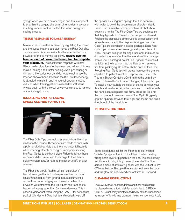
INSTALLING AND REPLACING SINGLE USE FIBER OPTIC TIPS
The Fiber Optic Tips conduct laser energy from the laser diodes to the tissues. These fi bers are made of silica with a polymer cladding. Note that there are potential hazards when inserting, steeply bending, or improperly securing the Fiber Optics to the hand piece. Failure to follow these recommendations may lead to damage to the Fiber or delivery system and/or harm to the patient, staff, or laser operator.
The Fiber is relatively fl exible, but can be broken if bent at an angle that is too sharp or a radius that is too small.Protein debris from gingival tissue accumulates on the fi ber during surgery and the extreme heat that develops will deteriorate the Tip. Fibers can fracture if a blackened area greater than 3 - 4 mm develops. This is especiallyimportant when using the LASER for periodontal pocket debridement. Stop lasing and regularly wipe off
the tip with a 2 x 2 gauze sponge that has been wet with water to avoid the accumulation of protein debris. Do not use fl ammable solvents such as alcohol when cleaning a hot tip. The Fiber Optic Tips are designed so that they typically won’t need to be stripped or cleaved. Replace the disposable, single-use tip as necessary and for each new patient. The disposable, single-use Fiber Optic Tips are provided in a sealed package. Each Fiber Optic Tip contains apre-cleaved, pre-stripped piece of Fiber. They are designed for single-use only and must be discarded after use. Confi rm the integrity of the package before use; if damaged, do not use. Special care should be taken not to break or snap the fi ber when removing tips from packaging. Do not touch the ends of the Fiber. Re-using Fiber Optic tips will greatly increase the chance of patient-to-patient infection. Dispose used FiberOptic Tips in a Sharps Container. Confi rm that the unit’s Key Switch is turned to ‘OFF’ when changing Fiber Optic Tips. To install a new tip, hold the collar of the tip between your thumb and forefi nger, align the metal end of the fi ber with the handpiece receptacle and fi rmly press the Tip onto the handpiece. To remove a worn Fiber Optic Tip, gently grip the tip body between forefi nger and thumb and pull it directly out of the handpiece.
INITIATING THE FIBER
Some procedures call for the Fiber tip to be ‘initiated.’ ‘Initiation’ prepares the tip of the Fiber to retain heat by fusing a thin layer of pigment on the end. The easiest way to initiate a tip is by lightly moving the end of the Fiber across a piece of articulating paper with the unit set to 1W CW (see below). The tip will retain pigment from the paper and will glow. Do not exceed contact time of 1 second.
CLEANING INSTRUCTIONS
The SOL Diode Laser handpiece and fi ber cord should be cleaned using a liquid disinfectant similar to BIREX or CIDEX. Do not spray disinfectant directly onto the handpiece as ingress of liquids may damage internal components. Apply
9

DIRECTIONS FOR USE | SOL LASER | DENMAT 800.445.0345 | DENMAT.COM
with a damp gauze sponge or wipe. Wear gloves and observe all other safety precautions and infection control procedures.
� PROCEDURAL RECOMMENDATIONS FOR USING THE SOL LASER
Following procedure guidelines are provided as a guide only and have been developed based on information provided by experienced laser users and educators. Always review the patient’s history to evaluate possible contra-indication for use of local anesthesia or other complications. All clinical procedures performed with the SOL Diode Laser must be subjected to the same clinical judgment and care as with traditional techniques. Patient risk must always beconsidered and fully understood before clinical treatment. The clinician must completely understand the patient’s medical history prior to treatment.
CONTRAINDICATIONS
Exercise caution for general medical conditions that might contraindicate a local procedure. Such conditions may include allergy to local or topical anesthetics, heart disease, lung disease, bleeding disorders, and immune system defi ciency, or any medical conditions or medications that may contraindicate use of certain light/laser type sources associated with this device. Medical clearance from patient’s physician is advisable when doubt exists regarding treatment.
HARD TISSUE PROCEDURES
The SOL Laser is not indicated for hard tissue procedures. The SOL Diode Laser is attracted to melanin, hemoglobin and to some extent to water. Avoid prolonged exposure of the energy when working in and around the cervical areas of the tooth. Due to the thin layer of enamel in this area, energy may be absorbed by the hemoglobin in the pulp and pulpal hyperemia may occur. Extended exposure to such energy could cause patient discomfort and even lead to possible pulpal necrosis.
CALIBRATION
The SOL Laser uses solid-state circuitry to continuously monitor power output and adjusts the power supplied to the laser diode to maintain the output at the user defi ned setting. If the output levels are more than ± 20% of the
set value, the unit will shut off power to the laser diode and provide an Error Message Alert to the operator. If this happens, the unit should be turned off and allowed to sit for about fi ve (5) minutes, then turned on again. If the laser performs when retried, the microprocessor has been able to make adjustments and the unit will function. If the unit fails to fi re when retried, the device will need to be sent for re-calibration by DenMat Service Department. Recalibration is recommended at a minimum of one time per year based on average usage. The SOL may be returned to DenMat Service Department for recalibration. Alternatively, a calibrated laser power meter, approved for use with 810 nm laser devices, may be purchased to check laser output power. The power meter will also need to be calibrated at recommended intervals. SOL output should be checked at 0.5, 1.0, 2.0, and 3.0 watts. The power meter display should be within 20% of the meter reading. If not, replace the fi ber tip. If the output is outside the 20% tolerance the system must be returned to DenMat Service Department for recalibration. The SOL system cannot be recalibrated by the user or service contractor and this must not be attempted.
SINGLE USE TIPS FOR INFECTION CONTROL
Fiber Optic Tips are designed for single-use only and must be changed between patients. See Section “Installing and Replacing Single-Use Fiber Optic Tips” (page 9) for details.
CHECKING FIBER CONTINUITY
Prior to test fi ring and tip Initiation, illumination from the SOL aiming beam can be used to verify that there are no cracks or breaks in the system main fi ber or single use tips. During this procedure use caution to prevent accidental activation of the working beam with the foot switch. It is recommended that the foot switch is unplugged to prevent laser activation. While in any system Preset or Default Mode press the Ready key to activate the aiming beam. Place the distal end of the fi ber perpendicular to and about 5mm-10mm distance from a piece of white paper. Visible light should be transmitted from the tip and a well formed and focused round spot should appear. If the spot is diffused or not round in shape the single use fi ber may be defective. Replace it and try again. It the spot is still diffused or not round in shape the system main fi ber may need to be replaced (see Service and Troubleshooting page15). Contact your DenMat Representative for additional assistance.
10

DIRECTIONS FOR USE | SOL LASER | DENMAT 800.445.0345 | DENMAT.COM
The extent to which differences in the shape of the spot will be noticed on tissue interaction is dependent on any reduction in transmission. If the spot has a small unfocused effect it may still work as expected or the fi ber might need to be replaced.
TEST FIRING THE SOL DIODE LASER
Always test-fi re the SOL laser prior to using it intraorally. Use the Power On default setting or select any of the four presets. Press the Ready Key to enter the Ready Mode. Press the foot switch to activate the working beam for1 - 2 seconds while aiming the fi ber tip onto a 2 x 2 gauze sponge moistened with water. DO NOT USE ALCOHOL OR OTHER FLAMMABLE LIQUIDS TO WET THE SPONGE. Tip Initiation See section “Initiating the Fiber” for guidance. Not all soft tissue procedures require an initiated tip or contact with tissue. Those procedures that do notrequire contact will use a Fiber Optic Tip that has NOT been initiated, because to be effective in non-contactmode, laser energy must fl ow unimpeded from the tip.
USING THE SOL DIODE LASER
Before using the SOL Diode Laser for patient treatment, it is recommended that a sanitary, disposable single-use Barrier Sleeve be placed over the handpiece to reduce the chance for patient-to-patient cross-contamination. Barrier Sleeves are SINGLE USE ONLY. Reusing these sleeves will greatly increase the chance of patient-to-patient infection. Safely dispose following use. Contact your DenMat representative for replacement packages of Barrier Sleeves.
When using the SOL Diode Laser in contact with tissue make short quick brush strokes in light contact at the lowest power setting that will remove the target tissue. Remove debris that collects on the fi ber tip with a clean 2 x 2 gauze sponge moistened with water. DO NOT USE ALCOHOL OR OTHER FLAMMABLE LIQUIDS TO WET THE SPONGE.
When the laser is not in use and when the procedure has been completed press the Ready Key to return to the Stand-By Mode.
Turn the Key Switch counterclockwise to the “OFF” position remove and store in a safe and secure location when the laser is not in use.
Turn the rear Power Switch to the “OFF” position to conserve battery power.
Record the Power settings and total procedure times used for each procedure in the patient’s chart.
EXAMPLE:
Patient Name: Mary JonesProcedure: Gingivectomy # 6 and # 7#6 procedure time 90 seconds @ 1.0 Watts CW air cooled#7 procedure time 60 seconds @ 1.1 Watts CW air / water spray
� THE DENMAT HOLDINGS, LLC SYSTEM SPECIFICATION
THE SOL LASER IS CLASS II
SOL Laser relies upon having two layers of insulation surrounding live parts or by having reinforced insulation to prevent electric shock.
THE SOL LASER IS TYPE BF
BF As type B but with isolated or fl oating (F – type) applied part or parts.
CLASSIFICATION AGAINST FLAMMABLE VAPOS WITH AIR
SOL Laser is NOT suitable for use in the the presence of Flammable Anaesthetic Mixture with Air, Oxygen or Nitrous Oxide.
11

DIRECTIONS FOR USE | SOL LASER | DENMAT 800.445.0345 | DENMAT.COM
� SOL LASER SPECIFICATIONS
Laser Classifi cation: Laser diode Class 4 laser device(per IEC 60825-1:2007)Wavelength working beam: 808 nm +/- 5 nmBeam divergence: 9° +/- 1°Power range: 100mW to 3.0 Watts CW. 100mW to 5 Watts PulseFrequency (Pulsed): Fixed, 10 HzContinuous Wave (CW) Duty Cycle: Fixed 100%Pulse Mode Duty Cycle: Fixed 50%Aiming Beam Output: 2mW Maximum, adjustableAudible signal: Yes, adjustable On/OffVisual signal: Yes, adjustablePower Supply: 30 Watts +12VDC supplied from 100-240 VAC 50-60 Hz MODEL FW7362M/12Weight: 2.55 lbs.
COMPLIES WITH
IEC 60601-1, IEC 60601-2-22; IEC 60825-1:2007; IEC 60601-1-2, Class B Per EN 60601-1-2 as well as to US Federal Regulations for laser performance standards set out in 21CFR 1040.10 and 1040.11 except for deviations pursuant to laser notice 50 dated July 26, 2001.
HAND PIECE
Length: 4.75”Diameter: 0.575”Tip removal: Manual friction-fi tSanitizing: Wipe with appropriate disinfecting solution
FIBER OPTIC TIPS
Type: Removable, Single-Use DisposableMaterial: Fused Silica, coatedSize: 400 µm x 2 inchStyle: Polymer-clad fi ber
ACCESSORIES
Sanitary, disposable single-use only Barrier Sleeve for Handpiece400 µm Single-Use ONLY Fiber Optic TipsContact DenMat Sales to order accessories
� SOL SERVICE AND TROUBLESHOOTING
Recalibration is recommended at a minimum of one time per year based on average usage (see Calibration page13).
NO VISIBLE LIGHT OR DIFFUSE LIGHT TRANSMITTED BY THE AIMING BEAM
Illumination from the SOL aiming beam can be used to verify that there are no cracks or breaks in the system main fi ber or single use tips (see Checking Fiber Continuity page 13). Visible light should be transmitted from the tip and a well formed and focused round spot should be visible.
If there is NO VISIBLE LIGHT start by replacing the single use tip. If there is still NO VISIBLE LIGHT this is an indication that the system main fi ber has been damaged. See Replacing The Main Fiber in the following section.
If the spot is diffuse or not round in shape the single use fi ber may be defective. Replace it and try again. It the spot is still
diffused or not round in shape the system main fi ber may need to be replaced
The extent to which differences in the shape of the spot will be noticed on tissue interaction is dependent on any reduction in transmission. If the spot has a small unfocused effect it may still work as expected or the fi ber might need to be replaced.
REPLACING THE BATTERY
The following procedure is provided in the unlikely event that the system battery needs to be replaced.
WARNING FOR BATTERY REPLACEMENT: Replace battery ONLY with SOL Replacement Battery item number authorized by DenMat. Use of a different battery may present a risk of fi re or explosion. Keep away from children.
Charge battery only after it is properly installed in the SOL system and only with the SOL AD/DC Power Converter supplied with the system or Replacement SOL AC/DC Power Converter item number authorized by DenMat.
12

DIRECTIONS FOR USE | SOL LASER | DENMAT 800.445.0345 | DENMAT.COM
CAUTIONS FOR PROPER BATTERY DISPOSAL: The <100Wh Lithium Ion rechargeable battery used in the Den-Mat SOL is recyclable and contains 0% mercury, 0% lead, 0% cadmium.
Battery must be recycled or disposed of properly. State and local regulations concerning the recycling and disposal of Lithium Ion batteries vary so it is necessary understand and remain in compliance with these regulations when replacing the SOL system battery.
Please follow the disposal and recycle symbols on the battery label to ensure that it is disposed of properly in accordance with local laws and regulations.
The manufacturer of the battery pack is a member of the Rechargeable Battery Recycling Corporation & the battery bears the RBRC symbol which includes the phone number to call to fi nd your closest recycling location. The battery is accepted for recycling at all RBRC locations throughout North America. We encourage the use of recycling facilities for our products. For more information on Lithium Ion battery recycling:
In North America contact the Rechargeable Battery Recycling Corporation (RBRC) at:
www.call2recycle.org or phone 1-877-2-RECYCLE (1-877-273-2925)
In Europe contact the European Portable Battery Association (EPBA). www.epbaeurope.net”
INSTRUCTIONS:
DISCONNECT THE SYSTEM FOOT SWITCH USED FOR LASER ACTIVATION
VERIFY THE SYSTEM POWER AND KEY SWITCH ARE IN THE OFF POSITIONS
1) Place the system on its side as shown resting on a soft towel to prevent scratching. Using a 3/32 size Hex Tool remove four rubber feet from the bottom and remove the battery access panel.
2) Remove the battery. NOTE: Replace with new battery and attach bottom access panel.
REPLACING THE FIBER OPTIC HAND PIECE
13
CAUTIONS FOR OPTICAL FIBER REPLACEMENT: THE FOLLOWING REPAIR SHOULD ONLY BE PERFORMED BY A QUALIFIED LASER SERVICE TECHNICIAN.
USE THE REMOTE INTERLOCK FEATURE AS A SAFETY PRECAUTION DURING FIBER REPLACEMENT.
DISCONNECT THE SYSTEM FOOT SWITCH USED FOR LASER ACTIVATION
VERIFY THE SYSTEM POWER AND KEY SWITCH ARE IN THE OFF POSITIONS
ESD GROUNDING PRECAUTIONS SHOULD BE OBSERVED. FAILURE TO FOLLOW THESE INSTRUCTIONS MAY RESULT IN DAMAGE TO THE SYSTEM AND/OR SAFETY HAZARDS.
The following procedure is provided in the unlikely event that the system fi ber optic hand piece needs to be replaced.
1) Completely unwrap the fi ber from the fi ber wrap and carefully store on a counter top. Remove the outer cover of the fi ber wrap, using the fi ber replacement tool, by
DIRECTIONS FOR USE | SOL LASER | DENMAT 800.445.0345 | DENMAT.COM 14
depressing two locking/release tabs located inside the wind wheel at the 10:00 o’clock and 2:00 o’clock positions while simultaneously pulling the wind cover outward from the top. Once the wind cover is loosened continue to pull outward and down until it is removed.
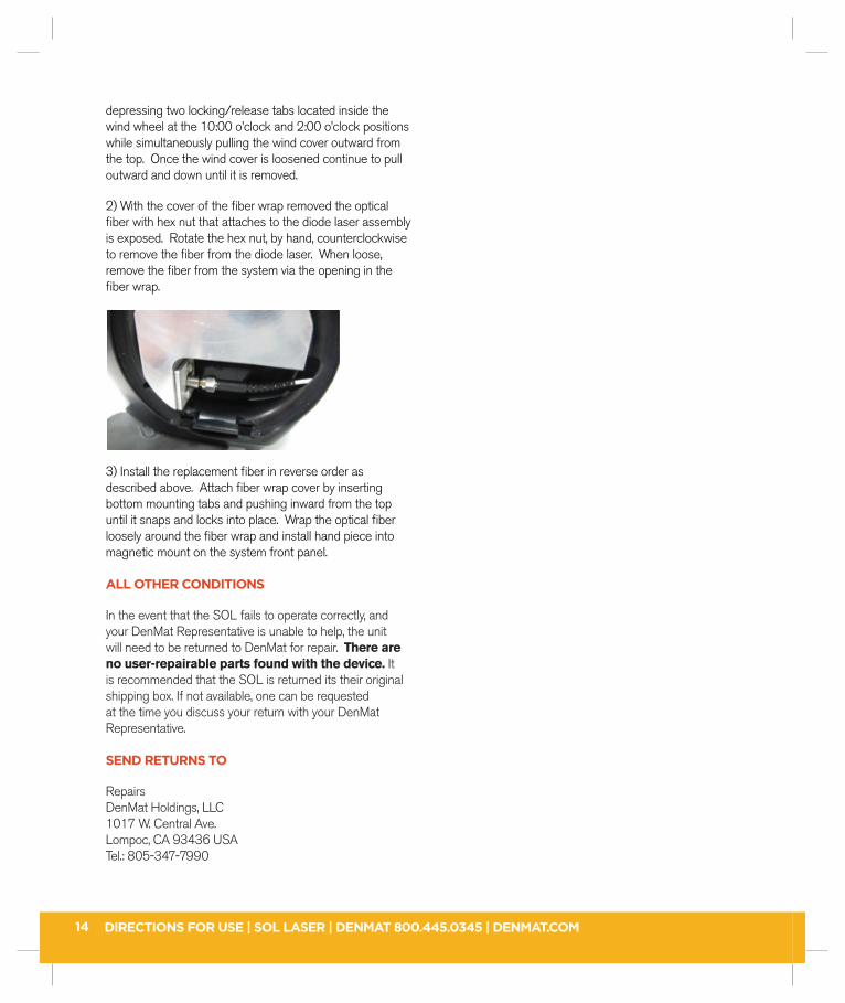
2) With the cover of the fi ber wrap removed the optical fi ber with hex nut that attaches to the diode laser assembly is exposed. Rotate the hex nut, by hand, counterclockwise to remove the fi ber from the diode laser. When loose, remove the fi ber from the system via the opening in the fi ber wrap.
3) Install the replacement fi ber in reverse order as described above. Attach fi ber wrap cover by inserting bottom mounting tabs and pushing inward from the top until it snaps and locks into place. Wrap the optical fi ber loosely around the fi ber wrap and install hand piece into magnetic mount on the system front panel.
ALL OTHER CONDITIONS
In the event that the SOL fails to operate correctly, and your DenMat Representative is unable to help, the unit will need to be returned to DenMat for repair. There are no user-repairable parts found with the device. It is recommended that the SOL is returned its their original shipping box. If not available, one can be requested at the time you discuss your return with your DenMat Representative.
SEND RETURNS TO
RepairsDenMat Holdings, LLC1017 W. Central Ave.Lompoc, CA 93436 USATel.: 805-347-7990

DIRECTIONS FOR USE | SOL LASER | DENMAT 800.445.0345 | DENMAT.COM 15

DIRECTIONS FOR USE | SOL LASER | DENMAT 800.445.0345 | DENMAT.COM

DIRECTIONS FOR USE | SOL LASER | DENMAT 800.445.0345 | DENMAT.COM

SOL. Everything you want in a laser.Call DenMat at 800.445.0345 or visit DenMat.com.
©2013 DenMat Holdings, LLC • 1017 W. Central Ave., Lompoc, CA 93436 USA 823057530 04/13 MO