instructions for use aorfix aaa flexible stent graft system
TRANSCRIPT

Lombard Medical, Ltd.
Not for use in the USA
PN03848 Revision C Page 1 of 44
Instructions for Use
Aorfix™ AAA Flexible Stent Graft System with
IntelliFlex™ Low Profile Delivery System

Lombard Medical, Ltd.
Not for use in the USA
PN03848 Revision C Page 2 of 44
TABLE OF CONTENTS
DEVICE DESCRIPTION ..................................................................................................... 4 1.1 Introduction .................................................................................................... 4 1.2 Main Body ...................................................................................................... 5 1.3 Contralateral (Plug-In) Leg ............................................................................. 7 1.4 Proximal and Distal Extender Components .................................................... 8 1.5 Aorto-Uni-Iliac Converter (AUI Converter) ...................................................... 9 1.6 IntelliFlex™ Low Profile Main Body Delivery System .................................... 10 1.7 IntelliFlex™ Low Profile Contralateral Delivery System ............................... 12 1.8 Ancillary Components Delivery Systems ...................................................... 14
INDICATIONS FOR USE .................................................................................................. 14 CONTRAINDICATIONS .................................................................................................... 14 WARNINGS AND PRECAUTIONS ................................................................................... 14
4.1 General ........................................................................................................ 14 4.2 Patient and Device Selection ....................................................................... 15 4.3 Implant Procedure ....................................................................................... 16 4.4 Use of Exchange Sheaths ............................................................................ 19 4.5 Follow-Up Imaging ....................................................................................... 19
ADVERSE EVENTS ......................................................................................................... 19 5.1 Potential Adverse Events ............................................................................. 19 5.2 Incident Reporting ........................................................................................ 20
PATIENT SELECTION AND TREATMENT ....................................................................... 20 6.1 Individualization of Treatment ...................................................................... 20 6.2 Specific Patient Populations ......................................................................... 23
PATIENT COUNSELING INFORMATION ......................................................................... 24 HOW SUPPLIED .............................................................................................................. 24
8.1 Sterility ......................................................................................................... 26 8.2 Contents ...................................................................................................... 27 8.3 Storage ........................................................................................................ 27
CLINICAL USE INFORMATION ........................................................................................ 27 9.1 Clinician Training ......................................................................................... 27 9.2 Inspection Prior to Use ................................................................................. 28 9.3 Materials Required ....................................................................................... 28 9.4 MRI Information ........................................................................................... 29
DIRECTIONS FOR USE ................................................................................................... 31 10.1 Patient Preparation ...................................................................................... 31 10.2 General Implant Procedure Precautions....................................................... 31 10.3 Implant Procedure and Deployment Instructions .......................................... 31 10.4 Deployment of Proximal Extenders (Cuffs) ................................................... 36 10.5 Deployment of Distal Extenders ................................................................... 39

Lombard Medical, Ltd.
Not for use in the USA
PN03848 Revision C Page 3 of 44
10.6 Use of exchange sheaths ............................................................................. 39 FOLLOW-UP IMAGING RECOMMENDATIONS: .............................................................. 41 11.1 X-ray ............................................................................................................ 41 11.2 Contrast CT ................................................................................................. 41 11.3 Non-Contrast CT .......................................................................................... 42 11.4 Duplex Ultrasound ....................................................................................... 42 11.5 MRI or MRA ................................................................................................. 42
TECHNICAL TRAINING .................................................................................................... 43 DISPOSAL ........................................................................................................................ 43 SYMBOL LEGEND ........................................................................................................... 43
Lombard Medical, Ltd.
Not for use in the USA
PN03848 Revision C Page 4 of 44
DEVICE DESCRIPTION
1.1 Introduction
The Aorfix™ Abdominal Aortic Aneurysm (AAA) Flexible Stent Graft System is an endovascular stent graft system for treating infra-renal aortic and aorto-iliac aneurysms. When placed within the aneurysm, the Aorfix AAA Flexible Stent Graft System creates an internal bypass of the aneurysm to reduce the risk of rupture.
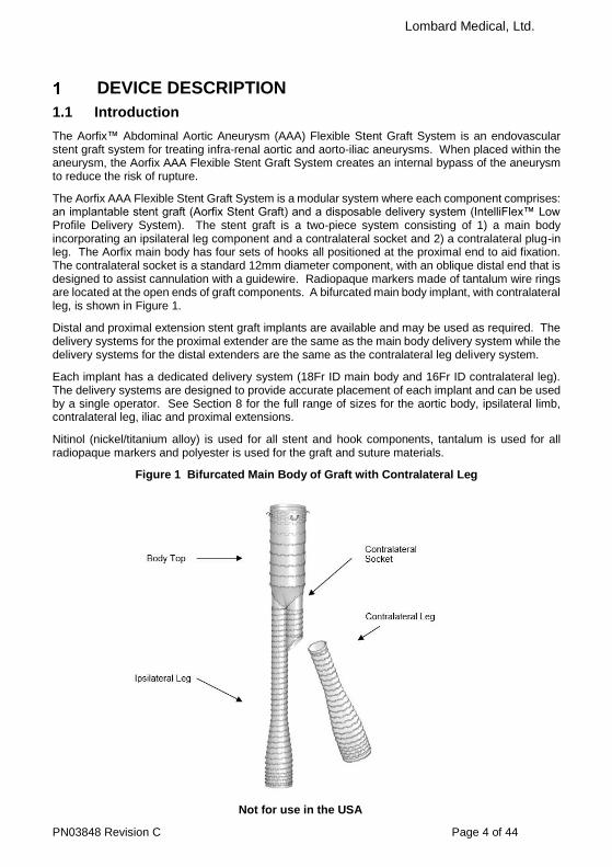
The Aorfix AAA Flexible Stent Graft System is a modular system where each component comprises: an implantable stent graft (Aorfix Stent Graft) and a disposable delivery system (IntelliFlex™ Low Profile Delivery System). The stent graft is a two-piece system consisting of 1) a main body incorporating an ipsilateral leg component and a contralateral socket and 2) a contralateral plug-in leg. The Aorfix main body has four sets of hooks all positioned at the proximal end to aid fixation. The contralateral socket is a standard 12mm diameter component, with an oblique distal end that is designed to assist cannulation with a guidewire. Radiopaque markers made of tantalum wire rings are located at the open ends of graft components. A bifurcated main body implant, with contralateral leg, is shown in Figure 1.
Distal and proximal extension stent graft implants are available and may be used as required. The delivery systems for the proximal extender are the same as the main body delivery system while the delivery systems for the distal extenders are the same as the contralateral leg delivery system.
Each implant has a dedicated delivery system (18Fr ID main body and 16Fr ID contralateral leg). The delivery systems are designed to provide accurate placement of each implant and can be used by a single operator. See Section 8 for the full range of sizes for the aortic body, ipsilateral limb, contralateral leg, iliac and proximal extensions.
Nitinol (nickel/titanium alloy) is used for all stent and hook components, tantalum is used for all radiopaque markers and polyester is used for the graft and suture materials.
Figure 1 Bifurcated Main Body of Graft with Contralateral Leg

Lombard Medical, Ltd.
Not for use in the USA
PN03848 Revision C Page 5 of 44
1.2 Main Body
The main body stent graft has three sections; the body top, the ipsilateral leg and the contralateral socket as described below. It is available with proximal diameters from 24mm to 31mm.
1.2.1 Body Top
The key features of the body top are shown in Figure 2. Hooks are positioned at four locations spaced 90° apart around the circumference at the proximal end and are designed to resist migration. A total of four pairs of hooks are used in Aorfix™. The reinforcing wire is in ring form, rather than a traditional zig-zag or diamond mesh stent. At the proximal end, the wire rings are placed closer together than in the body to increase radial force and they are also placed on the inside of the graft to improve the seal between the graft and the vessel wall. A radiopaque marker wire runs around the top of the device.
Figure 2 Main Body Hooks in Aorfix™ stent graft
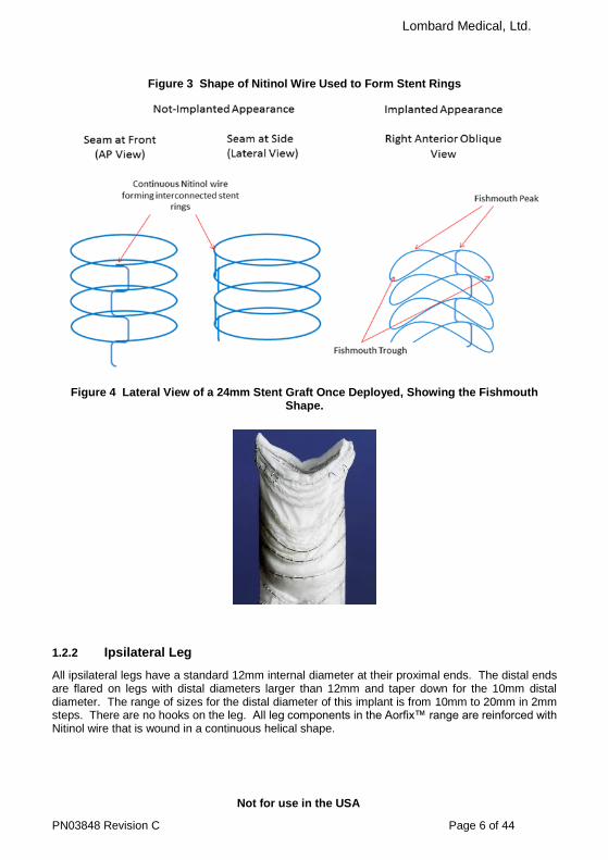
Figure 3 shows that the reinforcing wire in the main body is continuous and between stent rings, the wire is bent to run longitudinally in an offset, stepwise fashion. The longitudinal parts of the wire run in the seam of the device.
Note that when implanted, the stent graft rings are folded to have a saddle or ‘fishmouth’ shape, also shown in Figure 3 and photographed in Figure 4. This shape allows the stent graft to be placed trans-renally, with the fishmouth trough aligned with the renal arteries juxtarenally and the fishmouth peak extending suprarenally. Note that the seam referred to above is part of the fishmouth peak. The seam is less flexible than the rest of the graft and, in curved vessels, placing the seam on the inner curve should be avoided. This requirement and the orientation of the seam to the fishmouth are usually met by placing the device with the seam anteriorly in the patient with exact alignment determined by the orientation of the renal arteries. To aid this orientation, there is a longitudinal radiopaque wire running within the seam of the main body.
Lombard Medical, Ltd.
Not for use in the USA
PN03848 Revision C Page 6 of 44
Figure 3 Shape of Nitinol Wire Used to Form Stent Rings
Figure 4 Lateral View of a 24mm Stent Graft Once Deployed, Showing the Fishmouth Shape.
1.2.2 Ipsilateral Leg
All ipsilateral legs have a standard 12mm internal diameter at their proximal ends. The distal ends are flared on legs with distal diameters larger than 12mm and taper down for the 10mm distal diameter. The range of sizes for the distal diameter of this implant is from 10mm to 20mm in 2mm steps. There are no hooks on the leg. All leg components in the Aorfix™ range are reinforced with Nitinol wire that is wound in a continuous helical shape.

Lombard Medical, Ltd.
Not for use in the USA
PN03848 Revision C Page 7 of 44
1.2.3 Contralateral Socket
The socket also has a standard 12mm internal diameter and has an oblique distal end. There is a proximal radiopaque wire ring as well as the distal radiopaque ring to provide a visual guide to the clinician when cannulating the contralateral socket.
Note that the oblique entrance to the contralateral socket is not present in any of the 81mm long main body implants as shown in Figure 5.
Figure 5 Contralateral Sockets
Contralateral Socket used on Body lengths: 96mm, 111mm and 126mm
Contralateral Socket used on Body lengths: All 81mm
1.3 Contralateral (Plug-In) Leg
All contralateral legs have a standard 12mm internal diameter at their proximal ends. The distal ends are flared on legs with distal diameters larger than 12mm and taper down for the 10mm distal diameter. The range of sizes for the distal diameter of this implant is from 10mm to 20mm in 2mm steps. There are no hooks on the leg. All leg components in the Aorfix™ range are reinforced with Nitinol wire that is wound in a continuous helical shape.
The specified length of the leg is the working length, it is the length of implant that projects beyond the contralateral socket; the actual length of the implant is 40mm longer than the working length to provide for full over-lap in the socket.
Note: When using all 81mm bodies the socket is 15mm shorter than on all other body lengths, making the working length of the contralateral legs 15mm longer. For example, Figure 6 shows a 64mm contralateral leg. Its overall length is 104mm and it has a working length of 64mm when plugged into a 40mm socket which is found on all bodies except all 81mm. These main body grafts have a 25mm socket and this has the effect of increasing the working length of the contralateral leg to 79mm.
The working length for both socket sizes is indicated on the box label for contralateral legs.
25mm
15mm
25mm

Lombard Medical, Ltd.
Not for use in the USA
PN03848 Revision C Page 8 of 44
Figure 6 Dimensions of a Contralateral Plug-in Leg
1.4 Proximal and Distal Extender Components
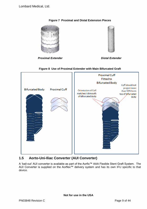
All extension pieces, shown in Figure 7, have the same diameter at both ends and have radiopaque wire rings at the proximal and distal openings to aid visualization.
Like the main body, the proximal extension pieces have hooks at the proximal end, the same design of nitinol rings, and radiopaque wire along the seam. They are available in diameters 24mm through 31mm. Shown in Figure 8, the proximal extender also has a fishmouth shape which should be deployed with the same orientation as the fishmouth of the main body.
The distal extender has the same construction as the leg components using helical wound Nitinol wire. It is available in diameters 10mm through 20mm.
Lombard Medical, Ltd.
Not for use in the USA
PN03848 Revision C Page 9 of 44
Figure 7 Proximal and Distal Extension Pieces
Proximal Extender Distal Extender
Figure 8 Use of Proximal Extender with Main Bifurcated Graft
1.5 Aorto-Uni-Iliac Converter (AUI Converter)
A ‘bail-out’ AUI converter is available as part of the Aorfix™ AAA Flexible Stent Graft System. The AUI Converter is supplied on the Aorflex™ delivery system and has its own IFU specific to that device.
Lombard Medical, Ltd.
Not for use in the USA
PN03848 Revision C Page 10 of 44
1.6 IntelliFlex™ Low Profile Main Body Delivery System
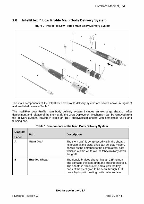
Figure 9 IntelliFlex Low Profile Main Body Delivery System
The main components of the IntelliFlex Low Profile delivery system are shown above in Figure 9 and are listed below in Table 1.
The IntelliFlex Low Profile main body delivery system includes an exchange sheath. After deployment and release of the stent-graft, the Graft Deployment Mechanism can be removed from the delivery system, leaving in place an 18Fr endovascular sheath with hemostatic valve and flushing port.
Table 1 Components of the Main Body Delivery System
Diagram
Label Part Description
A Stent Graft The stent graft is compressed within the sheath. Its proximal and distal ends can be clearly seen, as well as the entrance to the contralateral gate which is a plain white oval of fabric midway down the graft.
B Braided Sheath The double braided sheath has an 18Fr lumen and contains the stent graft and attachments to it. The sheath is translucent and allows the key parts of the stent graft to be seen through it. It has a hydrophilic coating on its outer surface.

Lombard Medical, Ltd.
Not for use in the USA
PN03848 Revision C Page 11 of 44
Diagram
Label Part Description
C Radiopaque Marker Band This band shows the position of the tip of the sheath under X-ray so that the progress of deployment can be seen.
D Proximal Handle The handle is firmly attached to, and stabilizes the delivery system while the controls on the delivery system are operated.
E Sheath Control This controls retraction of the sheath, in a counter clockwise motion.
F Orientation Mark The orientation mark is the origin of the exchange sheath flushing port, this indicates the anterior face of the implant.
G Shroud This cover slides toward the delivery system’s tip to give access to the Y-mechanism capture control.
H Y-Mechanism Capture Control
The control is used to compress the Y-mechanism before withdrawal of the delivery components through the exchange sheath.
I Bayonet Connection to Exchange Sheath
The bayonet connection attaches the deployment mechanism to the exchange sheath.
J Deployment Mechanism This mechanism includes the Flexible Tip, Y-mechanism, center tube and trigger wires. They are fully removable from the exchange sheath.
K Hemostatic Valve The Hemostatic valve is at the distal end of the exchange and controls blood loss when guidewires and larger endovascular components are passed through the sheath.
L Dilator The dilator can be introduced into the exchange sheath to permit repositioning or removal of the sheath.
M Trigger Wire Lock This control, when rotated, allows operation of the trigger wire release.
N Trigger Wire Release This control allows the trigger wires to be pulled out of the delivery system to release the stent graft.
O Exchange Sheath Flushing Port
This is used to flush the delivery system and exchange sheath. It acts as the anterior orientation marker.

Lombard Medical, Ltd.
Not for use in the USA
PN03848 Revision C Page 12 of 44
1.7 IntelliFlex™ Low Profile Contralateral Delivery System
Figure 10 IntelliFlex LP Contralateral Leg Delivery System
The main components of the IntelliFlex Low Profile contralateral delivery system are shown above in Figure 10 and are listed below in Table 2.
The IntelliFlex Low Profile contralateral delivery system includes an exchange sheath. After deployment and release of the stent-graft, the graft deployment mechanism can be removed from the delivery system to leave in place a 16Fr endovascular sheath with hemostatic valve and flushing port.

Lombard Medical, Ltd.
Not for use in the USA
PN03848 Revision C Page 13 of 44
Table 2 Components of the IntelliFlex™ Low Profile Contralateral Delivery System
Diagram Label
Part Description
A Stent Graft The stent graft is compressed within the sheath. Its proximal and distal ends can be clearly seen.
B Braided Sheath The double braided sheath has a 16Fr lumen and contains the stent graft and attachments to it. The sheath is translucent and allows the key parts of the stent graft to be seen through it. It has a hydrophilic coating on its outer surface.
C Radiopaque Marker Band This band shows the position of the tip of the sheath under X-ray so that the progress of deployment can be seen.
D Proximal Handle The handle is firmly attached to and stabilizes the delivery system while the controls on the delivery system are operated.
E Sheath Control This controls retraction of the sheath, in a counter clockwise motion.
F Bayonet Connection to Exchange Sheath
The bayonet connection attaches the deployment mechanism to the exchange sheath.
G Deployment Mechanism This mechanism includes the flexible tip, release-mechanism, center tube and trigger wires. They are fully removable from the exchange sheath.
H Hemostatic Valve The Hemostatic valve is at the distal end of the exchange and controls blood loss when guidewires and larger endovascular components are passed through the sheath.
I Dilator The dilator can be introduced into the exchange sheath to permit repositioning or removal of the sheath.
J Trigger Wire Lock This control, when rotated, allows operation of the trigger wire release.
K Trigger Wire Release This control allows the trigger wires to be pulled out of the delivery system to release the stent graft.
L Exchange Sheath Flushing Port
This is used to flush the delivery system and exchange sheath. It acts as the anterior orientation marker.
Lombard Medical, Ltd.
Not for use in the USA
PN03848 Revision C Page 14 of 44
1.8 Ancillary Components Delivery Systems
The proximal extender has the same delivery system as the main body implant. Distal extender pieces have the same delivery system as the contralateral leg. The AUI Converter is supplied on the Aorflex™ delivery system and has its own IFU specific to that device.
INDICATIONS FOR USE Aorfix™ is indicated for:
the endovascular treatment of infra-renal abdominal aortic, iliac and abdominal aorto-iliac aneurysms with peri-renal neck angles up to and including 90 degrees, including:
o Aortic neck landing zone diameters with a range of 19mm to 29 mm o Common iliac landing zone diameters with a range of 9mm to 19mm
CONTRAINDICATIONS The Aorfix AAA Flexible Stent Graft System is a contraindicated in:
Patients who have a condition that threatens to infect the graft.
Patients with known allergies or sensitivities to the implant materials (including, polyester, Nitinol and tantalum)
WARNINGS AND PRECAUTIONS
Read all instructions carefully. Failure to properly follow the instructions, warnings, and precautions may lead to serious consequences or injury to the patient.
Caution
The Aorfix Flexible Stent Graft System was the subject of a clinical trial (Pythagoras) involving 218 patients. The results of this trial are published in. J Vasc Surg, 62(5), 1108–18 and are referred to in the section below as ‘the PMA study’.
4.1 General
The Aorfix AAA Flexible Stent Graft System is for single patient use only. Do not reuse, reprocess or re-sterilize. Reuse, reprocessing or re-sterilisation may compromise the structural integrity of the device and/or lead to device failure that may result in patient injury, illness or death. Reuse, reprocessing or re-sterilisation may also create a risk of contamination of the device and/or cause patient infection, including, but not limited to, the transmission of infectious disease(s) from one patient to another. Contamination of the device may lead to injury, illness or death of the patient.
A conical or trapezoidal neck involving a diameter change of 5mm or more over its 15mm length or selection of a proximal landing zone 8mm or more distal to the distal renal artery may increase the risk of migration. More frequent imaging follow-up should be considered for such patients.
A substantial calcified plaque on a sharp, angled transition from neck to aneurysm sac has been seen to perforate the fabric of the graft in one subject in the PMA study and an additional patient in global experience. More frequent imaging follow-up should be considered for such patients.
Accurate fluoroscopic imaging is required during any endovascular procedure and for proper device deployment. Implantation of this device should occur in an operating room,

Lombard Medical, Ltd.
Not for use in the USA
PN03848 Revision C Page 15 of 44
endovascular suite, catheterization laboratory, or similar sterile environment, with appropriately trained personnel, and suitable equipment and imaging capabilities.
Do not use this device if the patient is unable to be evaluated using the necessary preoperative and postoperative imaging.
Always have a qualified surgery team available during implantation or re-intervention procedures in the event that conversion to open surgical repair is necessary.
The Aorfix™ AAA Flexible Stent Graft System should only be used by clinicians and teams experienced in endovascular techniques, and who have been trained in its use.
The long-term performance of this implant has not been established. All patients treated with this device must undergo periodic imaging to evaluate stent graft integrity and position, aneurysm size, and potential endoleaks and/or, occlusion of vessels in the treatment area. Significant aneurysm enlargement, a persistent endoleak, the appearance of a new endoleak, device migration, reduced blood flow through the graft, and/or decrease in renal function due to renal artery occlusion should prompt further investigation into the need for further patient treatment, including additional intervention or surgical conversion. Additional patient imaging follow-up should be considered for patients with devices that have effectiveness issues.
All patients should be carefully counselled on the need for long-term follow-up. The device is not recommended in patients unable or unwilling to comply with the information in Follow-up Imaging Recommendations.
4.2 Patient and Device Selection
Inappropriate patient or device selection may result in poor device performance. Patients should be assessed for suitability by the prescribing clinician who should take into account their knowledge of AAA surgery and Endovascular Aneurysm Repair (EVAR) including but not limited to the list below:
Access vessel diameter, vessel morphology and delivery system diameter should be compatible with vascular access techniques (femoral cut down or percutaneous). Vessels that are significantly calcified, occlusive, tortuous or thrombus-lined may preclude placement of the device or pose a risk of increased device complications. In patients with narrow access vessels, careful use of dilation, stenting or iliac conduits may allow introduction of the device.
Key anatomic elements that may affect exclusion of the aneurysm include very severe proximal neck angulation (>90°), short proximal aortic neck (< 15mm center-line length), distal iliac landing zone < 15mm, and inappropriate diameter selection for the intended landing zones.
Aortic necks with angles ≥60° may dilate substantially within 12 months’ dependent upon the extent of disease. Use adequate device over-sizing and note that close surveillance during follow-ups is necessary in these cases.
In aortic necks with angles ≥60° there is an increased risk of the proximal end landing obliquely. Ensure the stent graft is appropriately oversized.
Aortic necks that dilate by 5mm or more over their 15mm length have been associated with increased rates of migration. In four PMA study subjects suffering migration, the diameters of the necks increased by more than 5mm over their 15mm length. In two of these four cases grafts were also landed at least 8mm below the distal renal arteries.
Aortic necks where the anatomy only forms a suitable landing zone of 8mm or more distal to the distal renal artery have been associated with increased rates of migration.
Lombard Medical, Ltd.
Not for use in the USA
PN03848 Revision C Page 16 of 44
The presence of calcified plaques in the aortic neck, particularly those that line the transition between the bottom of the neck and the aneurysm sac, has caused wear leading to a late Type III endoleak in one subject in the PMA study and one further patient in global experience.
In aortic necks with angles ≥60° plan for ipsilateral to be the side where the delivery system encounters fewer changes in direction during insertion.
Irregular calcification, plaque or thrombus may compromise the fixation and/or sealing at the implantation sites.
Placement of the implant in an aorta with a diameter of 18mm or less in the region of the gate can result in occlusion of the ipsilateral limb.
The Aorfix™ AAA Flexible Stent Graft System has not been evaluated in patients who: o Are pregnant or nursing; o Are less than 21 years old; o Have traumatic aortic injury, ruptured aneurysms, aneurysms pending rupture
or require other emergent aorta or aneurysm treatment; o Have thoraco-abdominal, suprarenal or abdominal aneurysms where there is
no infrarenal neck or have ilio-femoral, mycotic, inflammatory, dissecting or pseudo-aneurysms;
o Have hypercoagulability, bleeding diathesis or coagulopathy; o Have mesenteric or celiac artery occlusive disease, giving rise to a dominant
patent inferior mesenteric artery; o Have connective tissue disorder or congenital degenerative collagen disease
(e.g., Marfan’s or Ehler’s-Danlos Syndrome); o Require bilateral exclusion of hypogastric blood flow; o Have baseline serum creatinine level of > 2.5 mg/dl; o Have other medical, social or psychological conditions that preclude them from
receiving the pre-treatment, required treatment, and post-treatment procedures and evaluations.
This device is not recommended in patients who: have or are suspected of having an active systemic infection; cannot tolerate imaging contrast agents, or have sensitivities or allergies to the stent graft system materials, antiplatelets or anticoagulants; have unstable angina; have had a myocardial infarction (MI) or cerebral vascular accident (CVA) within 6 months prior to implantation; or exceed weight and/or size limits necessary to meet institution-defined imaging requirements.
4.3 Implant Procedure
Refer to Section 10 for warnings and cautions specific to the implant steps of the Aorfix AAA Flexible Stent Graft System.
Pre-operative planning for access and placement should be performed before opening the device packaging.
Ensure that all stent graft components potentially required are available before starting the procedure.
Renal complications may occur: o from an excess use of contrast agents o as a result of embolic shower o from misplaced stent graft
Ensure that the fishmouth is correctly orientated with respect to the renal arteries to avoid their inadvertent occlusion. Correctly identify the orientation of the fishmouth through the sheath of the graft before introduction into the patient.

Lombard Medical, Ltd.
Not for use in the USA
PN03848 Revision C Page 17 of 44
Ensure that the anterior peak of the fishmouth does not impinge or occlude the superior mesenteric artery. Plan to deploy within 8mm of the distal renal artery. Landing more distally has been associated with increased risk of migration. In four subjects suffering migration, grafts were landed at least 8mm below the distal renal arteries. In two of these four cases, the diameters of the necks also increased by more than 5mm over their 15mm length.
The patient’s blood pressure can push the delivery system back through the access vessels unless it is held in place.
Failure to operate the Y-mechanism collapse control may result in displacement of the graft during removal of the delivery system.
Carefully inspect the device packaging and device for damage or defects prior to use. If signs of damage or defects exist or if premature breach of the sterile barrier is observed, do not use the device.
Minimize handling of the delivery system during preparation and insertion to decrease the risk of contamination and infection.
Do not re-sterilize any components of the Aorfix™ AAA Flexible Stent Graft System.
Systemic anticoagulation should be used during the implantation procedure, based on hospital or clinician protocol. If heparin is contraindicated, an alternative anticoagulant should be considered.
Over-lengthy occlusion of the ipsilateral vessels, particularly with light systemic anticoagulation can result in vessel occlusion.
Use fluoroscopic guidance to advance the delivery system and to detect kinking or alignment problems with the stent graft components.
Exercise care in handling and delivery techniques to help prevent vessel rupture.
Exercise particular care in difficult areas, such as areas of stenosis, intravascular thrombosis, or in calcified or tortuous vessels. Consider performing serial dilatation or balloon angioplasty at the site of a narrowed or stenotic vessel, and then attempt gently to reintroduce the delivery system.
If the sheath is accidentally withdrawn, the implant will prematurely deploy and may be incorrectly positioned.
Use magnification when visualising the renal landing zone to improve accuracy of placement.
Inaccurate placement or an inadequate seal zone may result in an increased risk of leakage into the aneurysm or migration of the stent graft.
Do not use excessive force to advance or withdraw the delivery system when resistance is encountered. If the delivery system kinks during insertion, do not attempt to deploy the stent graft component; remove the device and replace it with a new one.
Stent graft components cannot be replaced or drawn back into the delivery system, even if the stent graft component is only partially deployed.
Inadvertent partial deployment or migration of the stent graft may require surgical removal or repair.
Use of a non-stiff guidewire may result in an inability to navigate the vasculature. In tortuous vessels, this can lead to rupture.
The deployment plan should not expect an angled neck to straighten by the use of a stiff guidewire.
Initiate deployment of the proximal end of the stent graft in the straight section of the aorta slightly above the renals and pull the delivery system distally as the fishmouth opens.
Deploy the stent graft at a slow pace continuously observing the position of the proximal end of the stent graft.

Lombard Medical, Ltd.
Not for use in the USA
PN03848 Revision C Page 18 of 44
Do not rely on a ‘road-map’ image remaining accurate throughout deployment. Re-visualise anatomic landmarks, such as the renal arteries, at frequent intervals during deployment.
Do not manipulate the proximal part of the graft after the fishmouth is deployed
High pressure injections of contrast media made at the edges of the stent graft immediately after implantation may cause endoleak.
Confirm cannulation of the aortic body contralateral lumen to ensure accurate placement of the contralateral leg.
After cannulation, take care not to insert the guidewire between the stent graft fabric and a suture or wire support otherwise the leg delivery system may push the stent graft proximally.
The position of the proximal end of the implant is not considered fixed until the hooks have been engaged after ballooning. Take care to ensure that the proximal end of the implant is not displaced.
As a result of the fishmouth shape at the proximal end of the stent graft, it is necessary to balloon parts of the aorta that are not completely covered by the stent graft. When a balloon catheter is used, do not inflate to greater than the diameter of the aorta. Do not balloon completely outside the stent graft. Be aware that vessel rupture can occur even when the balloon is fully within the graft. Follow all manufacturer instructions regarding catheter operation.
Any endoleak left untreated during the implantation procedure must be carefully monitored after implantation.
When deploying the stent graft, be sure to hold the handle of the delivery system stationary.
Take extra care in angulated necks not to displace the implant when withdrawing the delivery system.
Failure to dilate fully the proximal end of a distal extender can result in limb occlusion.
Use of a distal extender in a leg which has a smaller diameter than the distal extender can result in stenosis or occlusion.
Insertion of a distal extender with more than 20mm overlap into a leg graft risks compressing the proximal part of the extender with the tapered part of the leg graft. This can lead to stenosis or occlusion.
When deploying the proximal cuff, ensure that its orientation and axial position are carefully controlled to avoid encroachment or covering the renal arteries.
The proximal extender is short, and deploys quickly. Ensure full planning has taken place before deployment.
When deploying the proximal extender, it is essential that the extension distance is measured apex to apex rather than trough to trough. This is because the troughs of the extender move slightly proximally during final ballooning.
Use of a stent material other than Nitinol may increase the risk of corrosion arising from dissimilar metals.
Patients who experience hypersensitivity reactions during the procedure should be managed in accordance with standard recommendations for treatment of patients with radiocontrast agent allergies (e.g., antihistamines, corticosteroids, adrenaline).

Lombard Medical, Ltd.
Not for use in the USA
PN03848 Revision C Page 19 of 44
4.4 Use of Exchange Sheaths
Before withdrawing or inserting the sheath through tortuous anatomy, insert the dilator through the sheath to avoid vessel damage or possible kinking.
Ensure that the correctly sized supplied dilator is used when advancing the sheath into the patient.
Ensure that the lumen of the exchange sheath is large enough to allow passage of instruments or catheters through its lumen.
Instruments or catheters used with the exchange sheath should move firmly but smoothly through the valve and sheath. The valve can be damaged or cause damage to instruments or catheters if too tight a fit.
When inserting, manipulating or withdrawing a device through an exchange sheath, always stabilize the position of the exchange sheath.
The exchange sheath can be pushed out of the patient by blood pressure if it is not stabilised.
Before removing or inserting devices through the exchange sheath, aspirate through the flushing port to clear the lumen, then flush with heparinized saline.
Note that the exchange sheath cannot be flushed when the dilator is in place.
Take care when passing the dilator tip through the hemostatic valve to avoid damaging the valve. If the dilator does not pass smoothly, reposition the tip and try again.
When inflating a balloon at, or close to, the tip of the sheath, ensure no part of the balloon is inside the sheath.
When puncturing, suturing or incising the tissue near the exchange sheath, use caution to avoid damaging the sheath.
Do not attempt to insert or withdraw the guidewire or introducer if resistance is felt.
When a leg delivery system is used in combination with main body or proximal cuff exchange sheath, ensure that the sheath of the leg delivery system projects through the tip of the larger size exchange sheath. This is achieved when the hub of the delivery system is in contact with the hemostatic valve of the exchange sheath.
4.5 Follow-Up Imaging
Patients with particularly challenging anatomy, including those with aortic neck anatomy that lies outside the indications of this IFU, patients with trapezoidal necks with a diameter change of 5mm or more over 15mm, those in whom the proximal landing zone could not be juxta-renal, particularly if the lowest part of the fishmouth is 8mm or more distal to the distal renal artery, those with high levels of calcified plaque at the transition of the aortic neck to the aneurysm sac and those in whom barb fracture has been detected should be followed diligently with consideration given to more frequent follow-up. Late migration, sac expansion, aneurysm rupture and fracture have occurred in such patients.
ADVERSE EVENTS
5.1 Potential Adverse Events
Potential adverse events related to the procedure or device malfunction include, but are not limited to:
Insertion and other vascular access site complications for example infection, dissection, bleeding, pain, delayed healing, hematoma, dehiscence, seroma, cellulitis, nerve injury/damage, arteriovenous fistula;
Allergic reaction and/or anaphylactic response for example to x–ray contrast dye, anti-platelet therapy, device materials;
Anaesthetic complications and subsequent attendant problems;

Lombard Medical, Ltd.
Not for use in the USA
PN03848 Revision C Page 20 of 44
Blood or bleeding events for example haemorrhage, anaemia, gastrointestinal bleeding, coagulopathy;
Bowel events for example bowel ischemia, paralytic or adynamic ileus, obstruction, fistulae;
Cardiac events consequent to general anaesthesia and abdominal surgery and, for example, transient aortic occlusion during ballooning;
Death;
Loss of stent graft function arising from, for example, improper component placement or deployment, component migration, occlusion, infection, loss of integrity requiring surgical revision, perforation and endoleak;
Embolic and thrombotic events (with transient or permanent ischemia or infarction), for example, deep vein thrombosis, renal embolism, micro embolic shower;
Arterial fistulae with, for example, vein, lymphatic, bowel;
Infection, for example urinary tract, systemic or localized, endograft, sepsis;
Generalized inflammatory response, for example, elevated temperature (post implantation syndrome);
Ischemic losses arising from, for example, planned or inadvertent occlusion of branch vessels including complications to systems such as: hepatic, gastric, splenic, bowel, neurologic, genitourinary and musculoskeletal;
Hepatic failure;
Lymphatic complications and subsequent attendant problems, for example, lymphocele, lymphatic fistula;
Multi-system organ failure;
Neurologic or cerebral events and subsequent attendant problems, for example, transient ischemic attacks, cerebrovascular accident (haemorrhagic or embolic), reversible ischemic neurologic deficit, nerve injury, paraparesis and paraplegia;
Pulmonary events consequent to general anaesthesia and abdominal surgery;
Renal complications, for example, acute and chronic renal failure, renal microembolism, renal insufficiency, renal artery occlusion, contrast toxicity;
Endovascular or surgical reintervention to correct deficit caused by, or loss of performance of, stent graft including surgical conversion to open repair;
Impotence/ sexual dysfunction;
Shock;
Vessel damage, for example, dissection, plaque disruption, rupture, thrombosis, occlusion and fistulae.
All adverse incidents should be reported to your local Aorfix™ supplier or direct to Lombard Medical.
5.2 Incident Reporting
All adverse incidents should be reported directly to Lombard Medical Inc. (address provided at end of document).
PATIENT SELECTION AND TREATMENT
6.1 Individualization of Treatment
Caution: Proper sizing of the Aorfix AAA Flexible Stent Graft System is the responsibility
of the clinician.
Each Aorfix AAA Stent Graft must be ordered in a size appropriate to fit the patient's anatomy. Clinicians should use adequate diagnostic techniques, including CT imaging, to fully evaluate the individual needs of the patient.
Lombard Medical, Ltd.
Not for use in the USA
PN03848 Revision C Page 21 of 44
The stent graft components should be oversized to be larger than the vessel’s inner diameter; aortic components should be oversized approximately 10-30% and leg components 0-20%.
Refer to Table 3 and Table 4 for guidance on device selection to achieve the selected degree of over sizing. Table 3 also gives a guide to the depth of fishmouth for all combinations of graft and aortic diameter.
The recommended overall length of the Aorfix™ Stent Graft, including additional components, should extend from the lowest renal artery to just above the internal iliac (hypogastric) artery.
All lengths and diameters of the stent graft components that may be needed to complete the procedure should be ordered by and available to the clinician, especially when there is a high degree of complexity in the anatomy that makes precise planning uncertain.
According to the extent to which the shape of the target vessels is changed by the insertion of stiff wires, the overall length of each stent graft component may appear to be shorter or longer when deployed.
Use of the implant in iliac arteries that have a distal landing zone less than 8mm in diameter poses an increased risk for implant complications and delivery system entrapment.
Ensure that access vessels are capable of accepting the delivery systems.
Clinicians may consult with Lombard Medical to assist in selecting appropriate components of the stent graft, based on the clinician's assessment of the patient's anatomical measurements.
Please note that vessel diameters are measured inner wall to inner wall (Internal Diameter or ID) in healthy landing zones. If the landing zone shows signs of disease, outer wall to outer wall measurements should be used.
Considerations for patient selection include but are not limited to:
Patient’s age and life expectancy
Co-morbidities (e.g., cardiac, pulmonary or renal insufficiency prior to surgery, morbid obesity)
Patient morphologic suitability for endovascular repair
Patient’s suitability for open surgical repair

Lombard Medical, Ltd.
Not for use in the USA
PN03848 Revision C Page 22 of 44
Table 3 Aortic Implant Selection Chart
Fishmouth Height (mm)
Aortic Diameter (mm)
19 20 21 22 23 24 25 26 27 28 29
Gra
ft D
iam
ete
r (m
m)
24 12 11 10 9 7 5 0 - - - -
25 13 12 11 10 9 7 5 0 - - -
26 14 13 12 11 10 9 7 5 0 - -
27 15 14 14 13 12 10 9 7 5 0 -
28 16 15 15 14 13 12 11 9 8 5 0
29 17 16 16 15 14 13 12 11 9 8 5
30 18 18 17 16 15 14 13 12 11 10 8
31 19 19 18 17 16 15 15 14 12 11 10
Key
Table 4 Iliac Implant Selection Chart
Stent Graft Diameter
(mm)
Iliac Internal Diameter, 10%
Over sizing
Iliac Internal Diameter, 20%
Over sizing
Iliac Internal Diameter, 30%
Over sizing
10 10 9 8
12 12 11 10
14 14 13 12
16 15 14 13
18 17 16 15
20 19 18 16
11 10% to 30% oversized, 11mm fishmouth height
12 5% or 35% oversized, 12mm fishmouth height
13 >35% or less than 5% oversized, 13mm fishmouth height

Lombard Medical, Ltd.
Not for use in the USA
PN03848 Revision C Page 23 of 44
6.2 Specific Patient Populations
Do not use the Aorfix™ AAA Flexible Stent Graft System in patients unable to undergo, or who will not be compliant with, the necessary preoperative and postoperative imaging and implantation procedures described in Sections 10 and 11.
The Aorfix AAA Flexible Stent Graft System is not recommended in patients who cannot tolerate contrast agents necessary for intraoperative and postoperative follow-up imaging.
The Aorfix AAA Flexible Stent Graft System is not recommended in patients exceeding weight and/or size limits necessary to meet imaging requirements.
Key anatomic elements that may affect successful exclusion of the aneurysm include short proximal aortic neck (<15mm, center-line length), pre-aneurysmal neck, thrombus and/or calcium formation at the arterial implantation sites, specifically in the proximal aortic neck and distal iliac artery interface. Irregular calcification and/or plaque may compromise the fixation and sealing of the implant. Necks exhibiting these key anatomic elements may lead to endoleak or graft migration.
Aortic necks that dilate by 5mm or more over their 15mm length have been associated with increased rates of migration.
Aortic necks where the anatomy only forms a suitable landing zone 8mm or more distal to the distal renal artery have been associated with increased rates of migration.
The presence of calcified plaques in the aortic neck, particularly those that line the transition between the bottom of the neck and the aneurysm sac, has caused wear leading to a late Type III endoleak in one subject in the PMA study and one further patient in global experience.
Adverse iliac anatomy, although potentially hazardous, is often amenable to adjunctive techniques, such as iliac conduits, stenting or serial dilation, which will enable the Aorfix Stent Graft to be deployed safely and effectively.
Inappropriate patient selection may result in implant performance that is poor or is not in accordance with its specifications.
The safety and effectiveness of the Aorfix AAA Flexible Stent Graft System has not been evaluated in patients who:
Are less than 21 years of age
Are pregnant or nursing
Have an aneurysm that is: o Mycotic o Inflammatory o Pseudoaneurysmal
Have an aortic neck < 15mm center-line length
Have a distance from the lower margin of the SMA to the distal end of the neck that is less than 20mm in length
Have a dominant patent inferior mesenteric artery as a consequence of having a compromised SMA
Require emergent aneurysm treatment, e.g., trauma or rupture
Have a history of bleeding diathesis or coagulopathy
Have had a myocardial infarction (MI) within 6 months prior to implantation
Have a known hypersensitivity or contraindication to anticoagulants, antiplatelet, or contrast media, which is not amenable to pre-treatment
Have an aneurysm with a proximal neck that has significant thrombus or calcified deposits
Lombard Medical, Ltd.
Not for use in the USA
PN03848 Revision C Page 24 of 44
Have arterial access that is not expected to accommodate the diameter of the delivery system as a result of size or tortuosity
Have an active infection at the time of the index procedure documented by pain, fever, drainage, positive culture and/or leukocytosis that is treated with antimicrobial agents (non-prophylactic)
Have congenital degenerative collagen disease, e.g., Marfan’s Syndrome
Have a creatinine level ≥ 2.5 mg/dl (or ≥ 221 μmol/L)
Are on dialysis
Have a connective tissue disorder
PATIENT COUNSELING INFORMATION
Prior to treatment, the clinician should review with the patient the risks and benefits of this endovascular procedure, including:
Risks and benefits of aneurysm repair given the patient’s age and life expectancy;
Risks, benefits and differences of open surgical repair;
Risks, benefits and differences of endovascular repair;
Risks related to non-interventional treatment (medical management);
Risks of aneurysm rupture as compared to the risk of endovascular repair;
The long-term safety and effectiveness of endovascular repair has not been established;
The importance of life-long, regular follow-up to assess patient’s health status and the stent graft performance;
Subsequent endovascular or open surgical repair of the aneurysm may be required;
Patients with specific clinical findings (e.g. endoleaks, enlarging aneurysms) should be monitored closely;
Signs to seek prompt medical attention (including limb occlusion, aneurysm enlargement, or rupture).
Lombard Medical recommends that the clinician disclose to the patient, in written form, all risks associated with treatment using the Aorfix™ AAA Flexible Stent Graft System. Details regarding risks occurring during and after implantation of the device are provided in Section 5. Additional counseling information can be found in the Patient Information Booklet.
HOW SUPPLIED
The Aorfix AAA Flexible Stent Graft System components are supplied individually boxed, double pouched and sterile. At least two components will typically be used in each procedure. Ensure that all devices that will potentially be needed to complete the procedure are available at the outset. The stent grafts are available in the following sizes and configurations, shown in Table 5 to Table 9.

Lombard Medical, Ltd.
Not for use in the USA
PN03848 Revision C Page 25 of 44
Table 5 Aortic Body and Attached Ipsilateral Limb Stent Graft Sizes – Diameters
Stent Graft Proximal Diameter
Catheter Working Length
Exchange Sheath Lumen
Stent Graft Distal Diameter (10mm to 20mm available with all proximal
diameters)
24mm
49.1cm 18Fr
10mm
25mm 12mm
26mm 14mm
27mm 16mm
28mm 18mm
29mm 20mm
30mm
31mm
Table 6 Aortic Body and Attached Ipsilateral Leg Stent Graft Sizes – Lengths
Main Body Stent Graft
Length
Iliac Leg Stent Graft Length Aorfix™
63mm 80mm 97mm
81mm
96mm
111mm
126mm
Table 7 Contralateral Leg Sizes
Stent Graft Proximal Diameter
Stent Graft Distal
Diameter
Catheter Working Length
Exchange Sheath Lumen
Stent Graft Length
(Available for all diameters)
12mm 10mm 79.7cm 16 Fr 56mm
12mm 64mm
14mm 73mm
16mm 81mm
18mm 90mm
20mm 98mm

Lombard Medical, Ltd.
Not for use in the USA
PN03848 Revision C Page 26 of 44
106mm
Table 8 Iliac Extension Sizes
Stent Graft Proximal and distal Diameters
Catheter Working Length
Exchange Sheath Lumen
Covered Stent Graft Length
10mm 79.7cm 16 Fr
51mm, 82mm
12mm
14mm
16mm
18mm
20mm
Use a distal extender diameter to match the distal diameter of the leg graft that is being extended.
Table 9 Proximal Extender Sizes
Stent Graft Proximal and distal Diameters
Catheter Working Length
Exchange Sheath Lumen
Covered Stent Graft Length
24mm 49.1cm 18Fr
38mm
25mm
26mm
27mm
28mm
29mm
30mm
31mm
Use a proximal extender diameter to match the aortic diameter of the primary graft.
8.1 Sterility
Each Aorfix™ Stent Graft (bifurcated body, contralateral leg and proximal or distal extensions) is individually contained within an IntelliFlex™ Low Profile Delivery System, which is sterilized using ethylene oxide (ETO) sterilization.
Inspect the device and packaging to verify that no damage has occurred as a result of shipping. Do not use this device if damaged or if the sterilization barrier had been damaged or broken.
Do not use after the expiration date printed on the label.
Lombard Medical, Ltd.
Not for use in the USA
PN03848 Revision C Page 27 of 44
For single patient use only. Do not reuse, reprocess or re-sterilize. Reuse, reprocessing or re-sterilization may compromise the structural integrity of the device and/or lead to device failure that may result in patient injury, illness or death. Reuse, reprocessing or re-sterilization may also create a risk of contamination of the device and/or cause patient infection, including, but not limited to, the transmission of infectious disease(s) from one patient to another. Contamination of the device may lead to injury, illness or death of the patient.
After use, dispose of the product and packaging in accordance with hospital, administrative and/or local government policy. If the device is damaged or the integrity of the sterilization barrier has been compromised, do not use the product and contact your Lombard Medical representative for return information.
8.2 Contents
One boxed, sterile, Aorfix™ AAA Flexible Stent Graft System device (One component).
With each individual shipment will be supplied:
One Instructions For Use (IFU)
8.3 Storage
Store in a cool dry place.
CLINICAL USE INFORMATION
9.1 Clinician Training
CAUTION: Always have a vascular surgery team available during implantation or re-intervention procedures in the event that conversion to open surgical repair is necessary.
CAUTION: The Aorfix AAA Flexible Stent Graft System should only be used by clinicians and teams trained in vascular interventional techniques and in the use of this device.
The recommended skill/knowledge requirements for clinicians using the Aorfix AAA Flexible Stent Graft System are outlined below. If you have questions about the product or sizing, contact your Lombard Medical Representative or via the information in the back of this manual.
Patient Selection:
Knowledge of the natural history of abdominal aortic aneurysm (AAA), co-morbidities, and complications associated with AAA repair.
Knowledge of radiographic image interpretation, device selection and sizing.
A multi-disciplinary team that has combined procedural experience with:
Femoral cut down, arterial bypass, arteriotomy, and repair
Percutaneous access and closure techniques
Non-selective and selective guidewire and catheter techniques
Fluoroscopic and angiographic image interpretation
Embolization
Angioplasty
Endovascular stent placement
Snare techniques
Appropriate use of radiographic contrast material
Techniques to minimize radiation exposure
Expertise in necessary patient follow-up modalities
Lombard Medical, Ltd.
Not for use in the USA
PN03848 Revision C Page 28 of 44
Lombard Medical supports all users of the stent graft system in order to realize its optimum performance. Support will be in the form of technical training given by qualified Lombard Medical staff and by the provision of training materials, as required. Details of support are available from your Lombard Medical representative. Lombard Medical has a formal, assessed training program which provides comprehensive training.
Lombard Medical requires that medical practitioners using the system are adequately trained in surgical and in particular endovascular techniques.
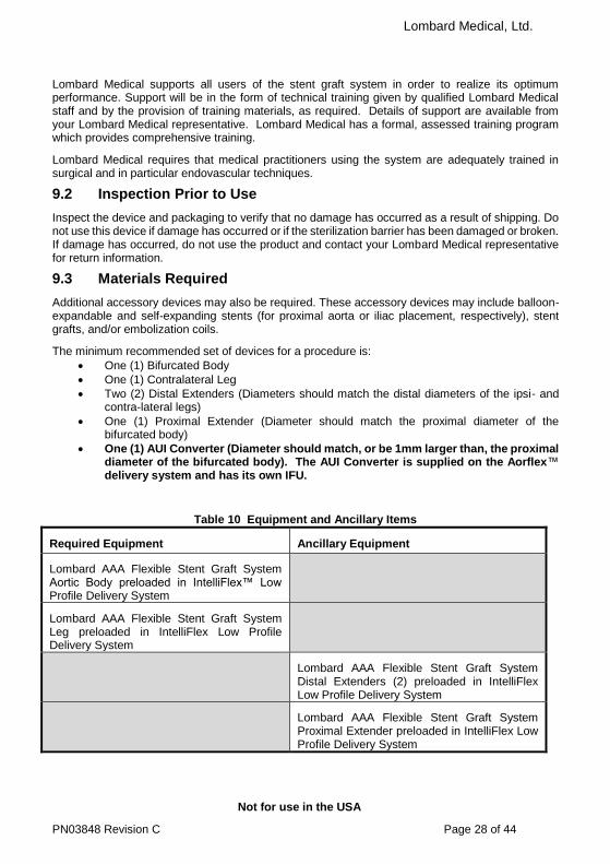
9.2 Inspection Prior to Use
Inspect the device and packaging to verify that no damage has occurred as a result of shipping. Do not use this device if damage has occurred or if the sterilization barrier has been damaged or broken. If damage has occurred, do not use the product and contact your Lombard Medical representative for return information.
9.3 Materials Required
Additional accessory devices may also be required. These accessory devices may include balloon-expandable and self-expanding stents (for proximal aorta or iliac placement, respectively), stent grafts, and/or embolization coils.
The minimum recommended set of devices for a procedure is:
One (1) Bifurcated Body
One (1) Contralateral Leg
Two (2) Distal Extenders (Diameters should match the distal diameters of the ipsi- and contra-lateral legs)
One (1) Proximal Extender (Diameter should match the proximal diameter of the bifurcated body)
One (1) AUI Converter (Diameter should match, or be 1mm larger than, the proximal diameter of the bifurcated body). The AUI Converter is supplied on the Aorflex™ delivery system and has its own IFU.
Table 10 Equipment and Ancillary Items
Required Equipment Ancillary Equipment
Lombard AAA Flexible Stent Graft System Aortic Body preloaded in IntelliFlex™ Low Profile Delivery System
Lombard AAA Flexible Stent Graft System Leg preloaded in IntelliFlex Low Profile Delivery System
Lombard AAA Flexible Stent Graft System Distal Extenders (2) preloaded in IntelliFlex Low Profile Delivery System
Lombard AAA Flexible Stent Graft System Proximal Extender preloaded in IntelliFlex Low Profile Delivery System

Lombard Medical, Ltd.
Not for use in the USA
PN03848 Revision C Page 29 of 44
Lombard AAA Flexible Stent Graft System Aorto-uni-iliac Bail-out Device preloaded in Aorflex™ Delivery System
Contralateral iliac occluder and cross-over graft
Imaging equipment with capability to record and recall all imaging
Imaging table, or operating room table designed for use with C-arm
Fixed or mobile C-arm with vascular software Appropriate personal protection equipment
for Fluoroscopy
Power injector with associated supplies
Angiography and exchange catheters
Assortment of adequate sizes (0.035” compatible)
and assorted lengths
Guidewires: Assorted sizes of clinician’s
preference, 0.035” compatible, 180cm compatible
Contrast media
Heparinized saline and flushing syringes
Oversized molding balloon
Introducer sheath for balloon
Vascular instruments and supplies
Caution: Use of a stent material other than Nitinol may increase the risk of corrosion arising from dissimilar metals.
Optional: Snare Serial dilators Non-compliant balloons for treatment of and
equivalent size to the distal iliac diameter; Compliant and non-compliant balloons for
treatment of, and equivalent size to, the aortic diameter.
Range of sizes self-expanding and balloon-expandable stents, including aortic sizes.
Embolization devices such as coils
9.4 MRI Information
Conditional
Lombard Medical, Ltd.
Not for use in the USA
PN03848 Revision C Page 30 of 44
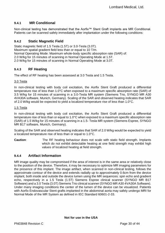
9.4.1 MR Conditional
Non-clinical testing has demonstrated that the Aorfix™ Stent Graft implants are MR Conditional. Patients can be scanned safely immediately after implantation under the following conditions:
9.4.2 Static Magnetic Field
Static magnetic field of 1.5 Tesla (1.5T) or 3.0-Tesla (3.0T). Maximum spatial gradient field less than or equal to 10 T/m. Normal Operating Mode: Maximum whole-body specific absorption rate (SAR) of: 2.0 W/kg for 15 minutes of scanning in Normal Operating Mode at 1.5T. 2.0 W/kg for 15 minutes of scanning in Normal Operating Mode at 3.0T.
9.4.3 RF Heating
The effect of RF heating has been assessed at 3.0 Tesla and 1.5 Tesla.
3.0 Tesla
In non-clinical testing with body coil excitation, the Aorfix Stent Graft produced a differential temperature rise of less than 1.0°C when exposed to a maximum specific absorption rate (SAR) of 3.5 W/kg for 15 minutes of scanning in a 3.0-Tesla MR system (Siemens Trio, SYNGO MR A30 4VA30A software, Munich, Germany). Scaling of the SAR and observed heating indicates that SAR of 2.0 W/kg would be expected to yield a localized temperature rise of less than 1.0°C.
1.5 Tesla
In non-clinical testing with body coil excitation, the Aorfix Stent Graft produced a differential temperature rise of less than or equal to 1.0°C when exposed to a maximum specific absorption rate (SAR) of 1.5 W/kg for 15 minutes of scanning in a 1.5- Tesla MR system (Siemens Espree, SYNGO MR B17 software, Munich, Germany).
Scaling of the SAR and observed heating indicates that SAR of 2.0 W/kg would be expected to yield a localized temperature rise of less than or equal to 1.0°C.
Caution: The RF heating behaviour does not scale with static field strength. Implants which do not exhibit detectable heating at one field strength may exhibit high values of localized heating at field strength.
9.4.4 Artifact Information
MR image quality may be compromised if the area of interest is in the same area or relatively close to the position of the device. Therefore, it may be necessary to optimize MR imaging parameters for the presence of this implant. The image artifact, when scanned in non-clinical testing, follows the approximate contour of the device and extends radially up to approximately 0.6cm from the device implant, both inside and outside the device lumen using the MR sequences: spin echo and gradient echo, respectively in a 1.5 Tesla (1.5T) Siemens Espree clinical scanner (SYNGO MR B17 Software) and a 3.0 Tesla (3.0T) Siemens Trio clinical scanner (SYNGO MR A30 4VA30A Software). Under many imaging conditions the center of the lumen of the device can be visualized. Patients with Aorfix Endovascular Stent grafts implanted in the abdominal aorta may safely undergo MRI for Normal Mode of the MR System as defined in IEC Standard 60601-2-33.

Lombard Medical, Ltd.
Not for use in the USA
PN03848 Revision C Page 31 of 44
DIRECTIONS FOR USE
10.1 Patient Preparation
In general, utilize similar patient pre-operative steps as for standard AAA open repair: fasting, bowel preparation, and prophylactic antibiotic regimens. Prepare and drape the patient for an open surgical AAA procedure, in the event that conversion to open repair is required.
The patient anaesthesia protocol utilized during the endovascular procedure is left to the discretion of the implanting clinician and anaesthesiologist. General anaesthesia, regional anaesthesia, or local anaesthesia combined with conscious sedation are all utilized during endovascular procedures.
Appropriate procedural imaging is required to successfully position the Aorfix™ AAA Flexible Stent Graft System in the vasculature and to assure appropriate arterial wall apposition. Always use fluoroscopy for guidance, delivery, and observation of the Aorfix AAA Flexible Stent Graft System within the vasculature.
10.2 General Implant Procedure Precautions
Do not kink the delivery systems which may cause damage.
Systemic anticoagulation should be used during the implantation procedure based on hospital and clinician preferred protocols. If heparin is contraindicated, an alternative anticoagulant should be considered.
Minimize handling of the stent graft constrained on the delivery catheter during preparation and insertion to decrease the risk of contamination and infection.
Do not continue advancement of the guidewire or delivery system if resistance is felt, as vessel or delivery system damage may occur. Stop and assess the cause of the resistance.
Inadvertent partial deployment or migration of the stent graft may require surgical removal or repair.
The deployment plan should not expect an angled neck to straighten by the use of a stiff guidewire.
Initiate deployment of the proximal end of the stent graft in the straight section of the aorta slightly above the renals and pull the delivery system distally as the fishmouth opens.
Deploy the stent graft at a slow pace continuously observing the position of the proximal end of the stent graft.
Do not rely on a ‘road-map’ image remaining accurate throughout deployment. Re-visualize anatomic landmarks, such as the renal arteries, at frequent intervals during deployment.
10.3 Implant Procedure and Deployment Instructions
10.3.1 Vascular Access and Imaging Set Up
1 Establish bilateral access using standard interventional techniques.
2
Be aware that in tortuous anatomy, significant deformation of the vessels is likely to take place upon insertion of the Aorfix Flexible Stent Graft System. It is common to defer most angiography until after the IntelliFlex™ Low Profile Delivery System is in place.
3
Set the C-arm perpendicular to the renal arteries by use of the appropriate oblique angle. In this view, both the left and right renal arteries should be seen at the very edge of the aorta. The oblique angle can be calculated from 3D CT reconstruction.

Lombard Medical, Ltd.
Not for use in the USA
PN03848 Revision C Page 32 of 44
4
Select the appropriate craniocaudal (CC) angle for fluoroscopy to match anterolaterally angled aortic necks. The CC angle will maximize the visible length of the neck to allow placement as precise as possible around the renal arteries.
5 Place an angiographic catheter suprarenaly from the contralateral side and perform angiographic assessment of patient’s vasculature.
6 Identify the renal arteries.
7 Insert a 0.035” guidewire on the ipsilateral side and position appropriately.
10.3.2 IntelliFlex™ Low Profile Delivery System Preparation
1 Inspect all packaging for damage or loss of sterile barrier, and that the components supplied match the patient’s requirements. Ensure that the “Use by” date has not been exceeded. If the device is not satisfactory for the above reasons, replace with another device.
2 Using sterile technique, remove delivery system from its sterile package and place it onto sterile field.
3 Inspect delivery system for damage; if present, replace device.
4 Flush delivery system and guidewire lumen with heparinized saline through both the luer connector at the distal end of the device and the sheath flushing port.
5 Activate the hydrophilic coating on the outside of the sheath by wetting it with saline.
10.3.3 Aortic Body Insertion and Deployment
1 Remove introducer sheath from ipsilateral access site (if applicable).
2 Identify anterior part of the graft through the sheath. The distal end of the socket, the seam of the aortic component and the four closely spaced wires on the outside of the graft at the proximal end should be clearly identified and the orientation of the delivery system adjusted so that these features lie anteriorly in the patient. Orientation of the anterior part of the graft can be confirmed by the position of the flushing port or Aorfix™ logo on the Handle.
Caution: Ensure that the fishmouth is correctly orientated with respect to the renal arteries to avoid their inadvertent occlusion. Correctly identify the orientation of the fishmouth through the sheath of the graft before introduction into the patient.
3 Load aortic body delivery system over guidewire.
4 Using continuous fluoroscopic guidance, insert delivery system into the vasculature and advance it until the troughs of the fishmouth at the proximal end of the device are at least 1cm proximal to the intended landing site.
5 Once the delivery system has been inserted, orientate the proximal end of the stent graft by viewing it directly under fluoroscopic control. It is helpful to identify the two arms of the Y-mechanism that are attached to either trough of the fishmouth within the delivery system. The arms will appear maximally separated within the sheath when they lie in the imaging plane. It can also be helpful to identify the oval marker for the contralateral gate, or the irregular RO marker line that lies within the seam of the aortic component, as both should lie on the anterior face of the graft. The anterior position of these structures can be checked by using a more lateral view, or, if the position of the fluoro must be held, rotation of the delivery system towards the patient’s left side should be accompanied by those markers also moving to the patient’s left.

Lombard Medical, Ltd.
Not for use in the USA
PN03848 Revision C Page 33 of 44
6 Place one hand on the proximal handle and the other on the sheath control. Hold the handle firmly so that the delivery system neither rotates nor slides into or out of the patient. Watching the fluoroscopic image at the proximal end of the stent graft, start to rotate the sheath control in the direction indicated by the printed arrows (labelled 1) on the control. The sheath will withdraw in short steps punctuated by clicks. Align the peaks of the fishmouth so that they lay one above the other in the fluoroscopic view.
Caution: The patient’s blood pressure can push the delivery system back through the access vessels unless it is held in place.
7 Manipulate the delivery system so the proximal end of the stent graft is aligned with the renal arteries. Place the trough of the fishmouth just inferior to the distal margin of the distal renal artery.
8 Ensure that the fishmouth will not occlude any part of the renal arteries when fully deployed. Check that the SMA has not been covered by the anterior peak. If necessary, use a lateral view to confirm patency.
Caution: Ensure that the anterior peak of the fishmouth does not impinge or occlude the superior mesenteric artery.
9 When satisfied with the position, rotate the sheath control further to deploy the fishmouth.
10 Continue to rotate the sheath control until the sheath has moved beyond the contralateral socket. The graft can be released from the Y-mechanism at this time. To release the graft, rotate the trigger wire lock in the direction indicated by the printed arrows (labelled 2) on the control. After 4 full revolutions of the trigger wire lock, pull the trigger wire release and withdraw the wires completely from the delivery system. This will disconnect the graft from the Y-mechanism.
11 To collapse the Y-mechanism. Push the shroud on the handle proximally as indicated by the printed arrow (labelled 3) to reveal the Y-mechanism capture control. Rotate the Y-mechanism capture control in a clockwise direction, as indicated by the printed arrows (labelled 4). A full revolution is required to collapse the Y-mechanism.
Warning: Failure to operate the Y-mechanism capture control may result in displacement of the graft during removal of the delivery system.
12 At this stage, the user can choose to continue with deployment of the rest of the ipsilateral leg or to cannulate the gate and implant the contralateral leg.
Caution: Over-lengthy occlusion of the ipsilateral vessels, particularly with light systemic anticoagulation can result in vessel occlusion.
13 Deploy the rest of the ipsilateral leg – See Section 10.3.6 below.

Lombard Medical, Ltd.
Not for use in the USA
PN03848 Revision C Page 34 of 44
10.3.4 Cannulation
1 Insert a floppy guidewire through a catheter on the contralateral side and into the open end of the gate. A GP or Vert catheter is recommended. Bring the tip proximal to the gate, rotate the tip to point posteriorly and pull gently down to allow the tip of the catheter to drop into the entrance to the contralateral gate. Gently push the guidewire up through the main body of the graft and well into the descending aorta.
2 Ensure that the guidewire is correctly within the lumen of the contralateral gate by rotating the C-arm through 180° from one lateral view to the opposite lateral view, watching constantly to ensure that the guidewire lies within the two RO marker rings at either end of the contralateral side.
Warning: After cannulation, take care not to insert the guidewire between the stent graft fabric and a suture or wire support otherwise the leg delivery system may push the stent graft proximally.
3 Exchange the floppy guidewire for a stiff 0.035” wire placed into the thoracic arch and remove the catheter.
Caution: The position of the proximal end of the implant is not considered fixed until the hooks have been engaged after ballooning. Take care to ensure that the proximal end of the implant is not displaced.
4 It is recommended that the proximal end of the stent graft is ballooned at this time.
10.3.5 Deployment of Contralateral Leg and Removal of Deployment Mechanism
1 Identify the radiopaque ring at the top of the socket and level with the flow divider which marks the lowest point at which the proximal ring of the plug-in leg can be positioned.
2 Accurately visualize the distal landing zone. Retrograde contrast injection by means of a contralateral placed sheath can be used to visualize the contralateral hypogastric artery.
3 Load delivery system over guidewire on the contralateral side and introduce the delivery system into the socket of the body implant.
Warning: Exercise particular care in difficult areas, such as areas of stenosis, intravascular thrombosis, or in calcified or tortuous vessels. Consider performing serial dilatation or balloon angioplasty at the site of a narrowed or stenotic vessel, and then attempt gently to reintroduce the delivery system.

Lombard Medical, Ltd.
Not for use in the USA
PN03848 Revision C Page 35 of 44
4 Place the entire radiopaque marker at the proximal end of the plug-in above the radiopaque ring at the proximal end of the socket. The most distal part of the marker on the plug-in should be in line with the radiopaque marker on the socket.
5 Place one hand on the proximal handle and the other on the sheath control. Hold the handle firmly so that the delivery system neither rotates nor slides into or out of the patient. Watching the fluoroscopic image at the proximal end of the stent graft, start to rotate the sheath control in the direction indicated by the printed arrows (labelled 1) on the control. The sheath will withdraw in short steps punctuated by clicks. Keep rotating the deployment control until the implant is fully deployed.
6 Release the delivery system from the proximal end of the stent graft. Rotate the trigger wire lock (labelled 2) in the direction indicated by the printed arrows on the control. After 4 full revolutions of the trigger wire lock, pull the trigger wire release and withdraw the wires completely from the delivery system.
7 Remove the graft deployment mechanism from the exchange sheath by rotating the deployment mechanism half a turn counter-clockwise and withdrawing the mechanism completely from the exchange sheath. This will not be possible until the sheath is fully retracted before bayonetting The handle can now be used as an exchange sheath.
10.3.6 Deployment of Ipsilateral Leg and Removal of Deployment Mechanism
1 Accurately visualize the distal landing zone. Contrast injection from a contralateral pigtail lying in the sac at the origin of the ipsilateral iliac artery can be used to visualize the ipsilateral hypogastric artery.
2 Deploy the rest of the ipsilateral leg by rotating the sheath control.
3 Ensure that the sheath is fully retracted and the Y-mechanism has been collapsed. Remove the graft deployment mechanism from the exchange sheath by rotating the deployment mechanism half a turn counter-clockwise and withdrawing the mechanism completely from the exchange sheath. This will not be possible until the sheath is fully retracted prior to bayonetting. The handle can now be used as an exchange sheath.
Top ring of Plug-in leg is above top ring of socket
Plug-in leg
Socket

Lombard Medical, Ltd.
Not for use in the USA
PN03848 Revision C Page 36 of 44
Warning: Take extra care in angulated necks not to displace the implant when withdrawing the delivery mechanism.
10.3.7 Ballooning
1 Insert an oversize moulding balloon over the guidewire in the ipsilateral leg and pass through the exchange sheath. Position the balloon at the proximal landing site in the aorta. Inflate the balloon to seal the implant fully. Deflate the balloon and move it down within the graft. Repeat ballooning process down the entire length of the graft, finishing at the distal landing site of the ipsilateral leg. Ensure that the wire rings on the body of the graft in the aneurysm sac have a regular smooth shape and that the ballooned graft fits the rings closely. Re-balloon if necessary. Repeat the ballooning process for the socket and contralateral leg to ensure seal.
2 When ballooning to resolve a Type 1 endoleak, it is recommended to inflate the balloon via a luer lock stop cock. When inflated, close the stop cock and keep the balloon inflated for 60 seconds before deflating. Repeat this process as needed.
Warning: As a result of the fishmouth shape at the proximal end of the stent graft, it is necessary to balloon parts of the aorta that are not completely covered with the stent graft. When a balloon catheter is used, do not inflate to greater than the diameter of the aorta. Do not balloon completely outside the stent graft. Be aware that vessel rupture can occur even when the balloon is fully within the graft. Follow all manufacturer instructions regarding catheter operation.
10.3.8 Completion
1 Insert a diagnostic catheter over the guidewire, remove the guidewire and perform completion angiography. Ensure the graft, renal arteries and hypogastric arteries are patent and that there is no evidence of an endoleak.
2 If no other interventions are required and aneurysm exclusion has been verified, remove the angiographic catheter and maintain guidewire position(s). If proximal or distal extension or Aorto-uni-iliac conversion is required, proceed with the appropriate steps below.
3 Remove catheters from both femoral arteries and close the wounds as per institutional protocol.
10.4 Deployment of Proximal Extenders (Cuffs)
10.4.1 General
1 The extender is intended to be used after the main graft has been deployed to correct inaccurate placement or to increase radial force of the main body graft.
2 The diameter of the extender should be the same as the diameter of the primary graft.
3 The extender is a short implant that has four pairs of hooks, a seam and a fishmouth shape identical to the primary graft. The fishmouth at the proximal end of the extender should be deployed with the same orientation as that of the primary graft.

Lombard Medical, Ltd.
Not for use in the USA
PN03848 Revision C Page 37 of 44
4 Preparation and deployment generally follows the description for deploying the Main Body in Section 10.3 above and is supplied in the same 18Fr delivery system, but be advised of variations in the steps listed below.
5 The extender for Aorfix™ has a length of 38mm, and is required to have a minimum overlap with the primary graft of 20mm. The extender is able to extend the main body graft proximally by a maximum of 18mm in Aorfix.
6 The extender has radiopaque marker wires around the proximal and distal circumferences and down its seam.
7 If access permits, the extender can be introduced through the contralateral side in order to achieve a different angle of approach to the aortic neck. The seam can be placed lying either anteriorly or posteriorly.
Caution The proximal extender is short and deploys quickly. Ensure full planning has taken place before deployment.
Warning When deploying the extender, ensure that its orientation and axial position are carefully controlled to avoid encroachment or covering the renal arteries.
10.4.2 Positioning and Deployment
1 Measure the length of additional coverage required (the extension, L) using appropriate diagnostic angiographic techniques; frequently this will be the distance from the distal margin of the distal renal artery to the trough of the fishmouth of the primary implant.
2 Adjust the C-arm view so that the two peaks of the fishmouth on the primary graft overlie each other.
3
4 Introduce the extender over the guidewire and advanced until the most proximal part of the extender lies proximal to the apices of the primary graft by the required (extension length, L). It may be helpful to draw a mark on the fluoro screen that indicates the intended position of the apex of the extender.
Caution: When deploying the proximal extender, it is essential that the extension distance is measured apex to apex rather than trough to trough. This

Lombard Medical, Ltd.
Not for use in the USA
PN03848 Revision C Page 38 of 44
is because the troughs of the extender move slightly proximally during final ballooning.
5
6 Exact orientation of the fishmouth of the extender is easier to achieve when it has been slightly deployed. Keeping the delivery system in place longitudinally, start to operate the sheath control by rotating it counterclockwise one click at a time. The extender will start to deploy at the sixth or seventh click and as soon as the implant is seen to start to emerge from the sheath, rotation of the sheath control should be halted and the orientation of the extender should be adjusted to match the primary graft.
7 The posterior and anterior apices should be adjusted to overlie each other by rotating the handle of the delivery system. Ensure that the proximal tips of the apices are aligned with the desired landing point.
8 Continue to operate the sheath control, rotating counterclockwise and, after each click, adjust the orientation and axial position of the extender.
9 Complete deployment of the extender and continue to turn the sheath control until the sheath is full retracted.
10 Ensure that the sheath is fully retracted and the Y-mechanism has been collapsed. Remove the graft deployment mechanism from the exchange sheath by rotating the deployment mechanism half a turn counter-clockwise and withdrawing the mechanism completely from the exchange sheath. This will not be possible until the sheath is fully retracted before bayonetting. The handle can now be used as an exchange sheath.
Warning: Take extra care in angulated necks not to displace the implant when withdrawing the delivery mechanism.
11 Balloon the extender using an oversized molding balloon as described in Section 10.3.7

Lombard Medical, Ltd.
Not for use in the USA
PN03848 Revision C Page 39 of 44
10.5 Deployment of Distal Extenders
10.5.1 General
1 The distal extender is intended to be used after the main graft and contralateral leg have been deployed to correct mal-positioning of the distal ends
2 The diameter of the extender should be the same as the diameter of the leg being extended
3 Preparation and deployment generally follows the description for deploying the contralateral leg and is supplied in the same 18Fr delivery system.
4 The extenders have overall lengths of 51mm or 82mm and are required to have a minimum overlap with the leg graft of 20mm.
5 The extenders have radiopaque marker wires around the proximal and distal circumferences.
Warning: Use of a distal extender in a leg which has a smaller diameter than the distal extender can result in stenosis or occlusion.
Warning: Insertion of a distal extender with more than 20mm overlap into a leg graft risks compressing the proximal part of the extender with the tapered part of the leg graft. This can lead to stenosis or occlusion.
Warning: Failure to dilate fully the proximal end of a distal extender can result in limb occlusion.
10.5.2 Deployment
1 Prepare the implant and delivery system as described in Section 10.3.2.
2 Perform appropriate angiograms to establish landmarks for distal sealing zones.
3 Distal extenders are deployed as described in Section 10.3.5.
10.6 Use of exchange sheaths
Once the deployment mechanism has been removed from the delivery system, the exchange sheath component of the delivery system remains in the patient. The sheath has a side flushing port and a hemostatic valve at the distal end. Appropriate dilators are supplied with each delivery system.
Warning: Before withdrawing or inserting the sheath through tortuous anatomy, insert the dilator through the sheath to avoid vessel damage or possible kinking.
10.6.1 Sheath Removal
1 The guidewire must be at least 10 cm past the tip of the sheath.
2 Insert the introducer dilator over the wire into the sheath.
3 Withdraw the sheath and dilator as a unit.

Lombard Medical, Ltd.
Not for use in the USA
PN03848 Revision C Page 40 of 44
10.6.2 Sheath Re-Introduction
The sheath will normally have been introduced during deployment of a stent graft component. If the sheath has been withdrawn from the patient, it can be re-introduced using the following technique:
1 Ensure the inner diameter (ID) of the introducer is appropriate for the maximum diameter of the instrument or catheter to be introduced.
2 Using the exchange sheath flushing port, flush the sheath by filling the assembly completely with heparinized saline.
3 Flush the dilator with heparinized solution.
4 Insert the dilator completely into the sheath.
5 Take care when passing the dilator through the hemostatic valve to avoid damaging the valve. If the dilator does not pass smoothly, reposition the tip and try again.
6 For best results, keep the device moist during placement. Reactivate the hydrophilic coating on the outside of the sheath by wetting it with saline.
7 Re-insert the dilator/sheath combination over wire guide through the dilator tip.
8 Remove the dilator, aspirate and flush through the exchange sheath flushing port.
9 Insert appropriately sized device as needed through the exchange sheath.
The contralateral limb or distal extender delivery systems (16Fr) can be used in combination with
the exchange sheaths of the main body and proximal cuffs (18Fr).
Caution: Ensure that the correctly sized supplied dilator is used when advancing the sheath into
the patient.
When a leg delivery system is used in combination with main body or proximal cuff exchange sheath, ensure that the sheath of the leg delivery system projects through the tip of the larger size exchange sheath. This is achieved when the hub of the delivery system is in contact with the hemostasis valve of the exchange sheath.
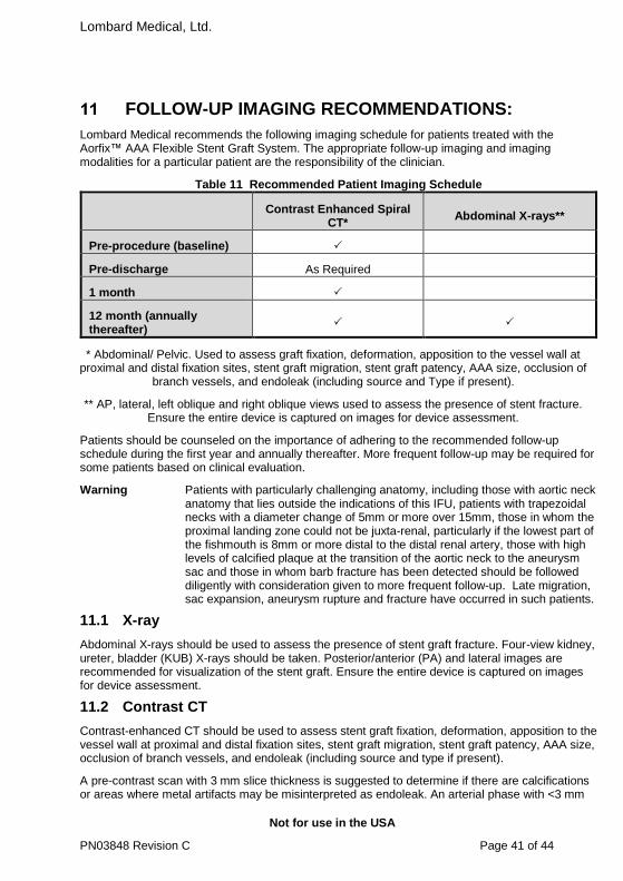
Lombard Medical, Ltd.
Not for use in the USA
PN03848 Revision C Page 41 of 44
FOLLOW-UP IMAGING RECOMMENDATIONS:
Lombard Medical recommends the following imaging schedule for patients treated with the Aorfix™ AAA Flexible Stent Graft System. The appropriate follow-up imaging and imaging modalities for a particular patient are the responsibility of the clinician.
Table 11 Recommended Patient Imaging Schedule
Contrast Enhanced Spiral
CT* Abdominal X-rays**
Pre-procedure (baseline)
Pre-discharge As Required
1 month
12 month (annually thereafter)
* Abdominal/ Pelvic. Used to assess graft fixation, deformation, apposition to the vessel wall at proximal and distal fixation sites, stent graft migration, stent graft patency, AAA size, occlusion of
branch vessels, and endoleak (including source and Type if present).
** AP, lateral, left oblique and right oblique views used to assess the presence of stent fracture. Ensure the entire device is captured on images for device assessment.
Patients should be counseled on the importance of adhering to the recommended follow-up schedule during the first year and annually thereafter. More frequent follow-up may be required for some patients based on clinical evaluation.
Warning Patients with particularly challenging anatomy, including those with aortic neck anatomy that lies outside the indications of this IFU, patients with trapezoidal necks with a diameter change of 5mm or more over 15mm, those in whom the proximal landing zone could not be juxta-renal, particularly if the lowest part of the fishmouth is 8mm or more distal to the distal renal artery, those with high levels of calcified plaque at the transition of the aortic neck to the aneurysm sac and those in whom barb fracture has been detected should be followed diligently with consideration given to more frequent follow-up. Late migration, sac expansion, aneurysm rupture and fracture have occurred in such patients.
11.1 X-ray
Abdominal X-rays should be used to assess the presence of stent graft fracture. Four-view kidney, ureter, bladder (KUB) X-rays should be taken. Posterior/anterior (PA) and lateral images are recommended for visualization of the stent graft. Ensure the entire device is captured on images for device assessment.
11.2 Contrast CT
Contrast-enhanced CT should be used to assess stent graft fixation, deformation, apposition to the vessel wall at proximal and distal fixation sites, stent graft migration, stent graft patency, AAA size, occlusion of branch vessels, and endoleak (including source and type if present).
A pre-contrast scan with 3 mm slice thickness is suggested to determine if there are calcifications or areas where metal artifacts may be misinterpreted as endoleak. An arterial phase with <3 mm

Lombard Medical, Ltd.
Not for use in the USA
PN03848 Revision C Page 42 of 44
slice thickness (preferably <2mm) and overlapping images with coverage from the celiac artery to the external iliac artery is recommended. In aneurysms that are not shrinking and have no apparent endoleak or fixation problems, a late venous phase scan may be performed. The venous phase scan may also be performed with thicker collimation (5 mm). It is recommended that the source data set be archived in case specialized evaluation is needed later (volume measurements, 3-dimensional reconstruction, or computer-aided measurement software). If the aneurysm is not shrinking by more than 5 mm within the first year, volume measurements may be obtained as a more sensitive indicator of AAA size using 3-dimensional software. The clinician will determine the requirement pre-operative care for patients with allergies to contrast.
11.3 Non-Contrast CT
For patients with impaired renal function, those who are allergic to contrast media and those showing significant sac shrinkage and freedom from endoleak, a spiral CT without contrast may be considered to assess stent graft fixation, deformation, apposition to the vessel wall at proximal and distal fixation sites, stent graft migration and size of the AAA with diameter and volume measurements.
11.4 Duplex Ultrasound
For patients with impaired renal function or those who are allergic to contrast media, a color-duplex ultrasound may be considered to assess: the size of AAA by diameter, endoleaks, stent graft occlusions and stenosis.
11.5 MRI or MRA
Patients with impaired renal function, i.e., renal insufficiency, may also be considered for magnetic resonance imaging or angiography (MRI, MRA) in facilities that have expertise in this area. Artifact may occur related to the stent, and care should be used to insure adequate imaging of the outer aneurysm wall to assess AAA size.
Volume measurement may be helpful if the aneurysm is not clearly shrinking. If there are concerns regarding imaging of calcified areas, fixation sites, or the outer wall of the aneurysm sac, adjunctive CT without contrast may be needed. Specific information on MRI can be found in Section 9.4.
Lombard Medical recommends contrast enhanced Spiral CT data for reconstruction using a slice thickness and interval of less than 3mm.
Patient motion should be avoided during scan. If possible, avoid scanning non-patient objects in field of view. Do not change patient position, table height, or field of view during scan. If patient moves, repeat the study in its entirety.
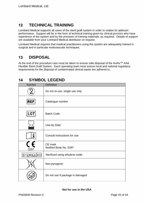
Lombard Medical, Ltd.
Not for use in the USA
PN03848 Revision C Page 43 of 44
TECHNICAL TRAINING
Lombard Medical supports all users of the stent graft system in order to realise its optimum performance. Support will be in the form of technical training given by clinical proctors who have experience of the system and by the provision of training materials, as required. Details of support are available from your Lombard Medical distributor on request.
Lombard Medical requires that medical practitioners using the system are adequately trained in surgical and in particular endovascular techniques.
DISPOSAL
At the end of the procedure care must be taken to ensure safe disposal of the Aorfix™ AAA Flexible Stent Graft System. Each operating team must ensure local and national regulatory requirements for the disposal of contaminated clinical waste are adhered to.
SYMBOL LEGEND Symbol Definition
Do not re-use, single use only
Catalogue number
Batch Code
Use-by Date
Consult instructions for use
0297
CE mark Notified Body No. 0297
Sterilized using ethylene oxide
Non-pyrogenic
Do not use if package is damaged

Lombard Medical, Ltd.
Not for use in the USA
PN03848 Revision C Page 44 of 44
United Kingdom
Lombard Medical Ltd
4 Trident Park
Didcot, OX11 7HJ
United Kingdom
Tel: +44 (0) 1235 750 800
Fax: +44 (0) 1235 750 879
Email: [email protected]
Caution: Federal (USA) law restricts this device to sale by or on the order of a clinician.
Manufacturer
MR Conditional (Applicable to implant only)
Caution