instructions for robo-dome™ observatoryapi/deki/files/1074/=robodome_ins... · metal rule (12 ft....
TRANSCRIPT

RD-1M Page 1
Revised 12/01/01
TECHNICAL INNOVATIONS 7851 Cessna Ave.
Gaithersburg, MD. 20879 301-977-9000
Instructions for ROBO-DOME™ Observatory
S/N ________________
Congratulations. You have purchased a ROBO-DOME® observatory, which will
serve you well in the years to come. We are sure your new dome will increase your enjoyment of astronomy. Although the ROBO-DOME arrives preassembled, you will be
installing it on some form of support and connecting electrical and electronic systems. It is essential that you read these instructions because the assembly involves the handling of fairly large structural pieces, use of power tools, and the need to perform some mechanical assembly. Assembly should be an enjoyable experience, so take your time and be careful. The ROBO-DOME incorporates the Digital Dome Works (DDW)
remote control system. Therefore, you should use this ROBO-DOME instruction manual for the installation, then move on to the DDW instruction manual for the detailed checkout and operation of your observatory. We hope and believe that you will be happy with this product. We
ask that you let us know of any suggestions or criticisms of our products. We have incorporated many ideas from customers into these instructions, and into the ROBO-DOME design. We thank all who contributed (and you are the beneficiary!) If, at any time, you have questions, please feel free to give us a call so we can help you. Our aim is for you to be satisfied! Jerry Smith Technical Innovations

RD-1M Page 2
CAUTION
Handling fiberglass improperly can result in skin injury, while failure to perform several easy, but crucial, steps in the ROBO-DOME assembly can cause the ROBO-DOME not to operate properly. In addition, failure to follow recommended assembly may result in injury during or after construction. Please at least scan all parts of these instructions, even those parts covering skills you already have. Technical Innovations is not responsible and assumes no liability for any damage or injury arising from assembly, installation, or use of this product. While the instructions include cautions and warnings, it is ultimately the customer who must exercise good judgment and care in the assembly and while the observatory is in use to avoid damage to materials or persons, and it is the customer who assumes all risk and liability.
NOTICE
All portions of this instruction manual are copyrighted by Technical Innovations, 1999,
and are protected under the laws of the United States. This document may not be reproduced without the consent of Technical Innovations except for use by the purchaser
during assembly.

RD-1M Page 3
PARTS LIST — RD-1.0 Fiberglass Pieces with PreAssembled Hardware: • Shutter. Includes dual rack, Teflon guide strips, Hold-Down brackets • Dome Section. Includes Sliding Contacts, dome wiring, microswitches for End of
Travel interlocks, Shutter Drive Motor (12V), shaft and dual shutter drive sprockets, Side Rails (for shutter), rotation drive rack (beneath equator flange)
• Base Section. Includes mounting board with DDW unit and Power Supply, wiring, Entry Switch and Pilot light, Hold Down clips (five total, two with sliders), Support Rollers (6), Side Rollers (3), Rotation Drive Motor (12V), Drive shaft and sprocket
Additional Robo-Dome Components: • Base flange layout template (paper, sent with order acknowledgment) • Special Tool for disassembling shutter • Silicone Caulk (1) • Installation Manual Additional DDW Components: • Key for Entry Switch • Extra Cables (3) and PC Adapters(2) for connection to computer • LX200 Adapter box • Hand Control • Instruction Manual and Software
TOOLS AND HARDWARE TO BE PROVIDED BY INSTALLER, NOT INCLUDED WITH ROBO-DOME
3/8 in electric drill with set of bits (2 drills are even more efficient) Metal rule (12 ft. longer) Carpenter level or water level Hand tools: clamps, screw drivers, socket wrench set, etc. Duct tape Caulking gun Gloves, eye protection Work table (e.g. sawhorses & plywood) Extension cord(s) Foundation bolts and fender washers Thin shims and spacers

RD-1M Page 4
TABLE OF CONTENTS
PARTS LIST — RD-1.0 ..................................................................................................3
1. Introduction to Instructions ..........................................................................................5 Safety Precautions ........................................................................................................................5 Fiberglass .....................................................................................................................................6 Construction and Operation Cautions ..........................................................................................7 Special Assembly Instructions .....................................................................................................7 Nomenclature ...............................................................................................................................7
2. Robo-Dome Installation ...............................................................................................8 Introduction ..................................................................................................................................8 Wiring Considerations .................................................................................................................9 Foundation ...................................................................................................................................10 Telescope Pier ..............................................................................................................................10 ROBO-DOME Floor ....................................................................................................................11 Robo-Dome Electronics ...............................................................................................................11 Installation Practices ....................................................................................................................12 Unpacking ....................................................................................................................................12 Mounting the Base .......................................................................................................................13 Electrical Installation Options ......................................................................................................14 Electrical Connections .................................................................................................................16 Install Dome/Shutter on Base .......................................................................................................16 Initial Testing of ROBO-DOME — DDW Off ............................................................................17 Initial Testing of ROBO-DOME — DDW ON ...........................................................................18 Computer Operation of Robo-Dome ............................................................................................19 Emergency Entry into ROBO-DOME. ........................................................................................20
3. Telescope Installation ..................................................................................................22 Introduction ..................................................................................................................................22 General Considerations ................................................................................................................22 Fitting the LX200 into the Robo-Dome .......................................................................................24 LX200 in Alt-Azimuth .................................................................................................................26 LX200 with Wedge Mounting .....................................................................................................26 Refractor on a GEM .....................................................................................................................26 Aligning the Mount ......................................................................................................................26
4. Telescope Camera (Video or CCD) Installation ..........................................................29 Focusing .......................................................................................................................................29 Cable Management .......................................................................................................................30 Counter Weights ..........................................................................................................................30 Space Needs .................................................................................................................................30
5. Use and Care of your ROBO-DOME ..........................................................................32
Appendix 1 List of Figures ..............................................................................................34
Appendix 2 DDW Modifications for ROBO-DOME ......................................................35
Appendix 3 Updates and Modifications to Design or Instructions ..................................36

RD-1M Page 5
1. Introduction to Instructions The ROBO-DOME with a telescope and camera is a robotic, remote controlled astronomical observatory. By connecting the ROBO-DOME to your computer, you can obtain views of the heavens that only a few years ago would have been the envy of the most advanced professional astronomers. Installation of your remote controlled observatory involves several steps: • Installing the ROBO-DOME • installing your telescope • installing your camera • checking and operating the system In this book, we describe the physical installation and initial checkout of each observatory component. There are also figures and other material at the back of this book to help you. Once the ROBO-DOME is installed and checked, we recommend that you switch to the instruction manual for Digital Dome Works, where we take you through a sample operating session and describe bringing the whole system on line. To simplify our discussion, we assume a typical system: • ROBO-DOME with Digital Dome Works • Meade LX200 remote controlled telescope. Although your telescope may be of a
different type, the basic ideas in the setup are the same. • On-line video camera. Although you may have a CCD camera (designed for longer
exposures at lower light levels), a video camera is quick to bring into operation and is suitable for observing the brighter objects. Installation of a typical CCD camera is discussed in a later chapter.
Because the ROBO-DOME system is so flexible, there are different ways to setup and operate the system. Although we describe the most common setups, we also bring in additional information so that you will be aware of alternatives.
Safety Precautions Constructing a ROBO-DOME requires you to follow several safety precautions and use common sense, since the activity does include mechanical and manual operations. Care is needed in the use of tools and you should follow the precautions provided by the manufacturers of any tools you may use. Since you will be installing a small building, you may need to use stepladders: so be careful. While the fiberglass parts are not very heavy, they are bulky: use care in handling them so that neither you nor the parts are injured. Carefully read all the instructions, and think through your activities before you commence. Make liberal use of props, tape, clamps, or other aids in the construction.

RD-1M Page 6
CAUTION
If the dome is to be installed on any support or wall more than three feet above the ground, or in a location with difficult outside access, we STRONGLY recommend that you set up and check out the dome on the ground where it is convenient and safe to work. You can then quickly move the Robo-Dome to the permanent location, knowing how the parts fit together, and with direct experience in handling the pieces.
Fiberglass Fiberglass is really a misnomer: the material is fiberglass reinforced plastic (FRP). In our case, the plastic is an isophthalic (polyester) resin (not epoxy). In its "raw" state, resin is a syrupy liquid. After mixing about 15 drops of catalyst per ounce of resin, it hardens in about an hour. Because the hardened resin is somewhat brittle, it is reinforced with fiberglass for strength, and to prevent the propagation of cracks. The fiberglass can be in the form of woven material which has the resin spread onto and into it, or long fiberglass strands which are chopped into 2 inch pieces, then mixed with resin that is sprayed into a mold. Our products are made with layers of mat. Fiberglass has many virtues, but also two potential problems:
FIBERGLASS IS FLAMMABLE
FIBERGLASS CAN IRRITATE THE SKIN Yes, fiberglass will burn, or rather, the plastic in it will burn. Once started, it does burn very hot (you might want to try a 1 square inch piece in a fireplace to see). Therefore, use common sense as you would with wood or any other flammable construction material. Keep fire and open flame away from all parts of your ROBO-DOME. Also, do not let fiberglass dust or trimmings accumulate. Be especially careful about this where there is any risk of flame or fire. The fiberglass within the FRP is glass, and it can cut or abrade the skin. Sharp edges of the dome pieces can cut, so be careful. Whenever handling FRP pieces, always wear gloves to be on the safe side. Of course, the surfaces of the FRP are smooth, because they have been coated with a layer of resin (called Gel-coat) that covers the glass. Fiberglass dust can irritate the eyes and skin. When cutting or trimming or filing or drilling -- in short, whenever doing something to the FRP that makes dust -- always use gloves and eye protection. Also, wear a long sleeved shirt and long pants. In addition, be sure to change your clothes and wash thoroughly when you are done the dusty part. If there is lots of dust, change how you are doing things to reduce the dust exposure! Reasonable care is all that is needed; however, failure to follow reasonable care could lead to eyes or skin that itches for a day or so. Hand lotion can help relieve itchy skin. If itching persists, see your physician.

RD-1M Page 7
Construction and Operation Cautions During construction and operation, there are specific cautions that must be followed. The ROBO-DOME observatory is not a toy, so be sure that children (and adults) do not climb upon it. Since the observatory does contain moving parts, users must be careful to avoid injury. Keep your fingers away from the moving parts where they might become caught.
Special Assembly Instructions This section contains special instructions that apply to several parts of the assembly and to special hardware issues. We have written these for the relatively unskilled assembler. However, even those who are skilled in carpentry or other mechanical assembly SHOULD read and follow these instructions, especially concerning leveling the structure.
Nomenclature Parts of the ROBO-DOME observatory have special names. These include the following. DomeTop. The rotating portion of the observatory is called the DomeTop. The word “dome” is often used to refer to the overall observatory. Home. The DomeTop is at “Home” when it is lined up with the Base. The dome must be in the Home position for the shutter to operate. Sliding Contacts. Sliding contacts are the metal ovals that slide on the stainless steel plates in the rear of the dome. These transmit electricity up to the DomeTop for operation of the shutter and other purposes. Equator Flange. If the dome were a hemisphere, the equator flange is at its equator. The dome equator flange rides on the rollers as it rotates.

RD-1M Page 8
2. Robo-Dome Installation
Introduction In this chapter, we describe the physical installation of the ROBO-DOME structure, connecting it to the computer, and the initial checkout. Although you will probably want to install the telescope at the same time, we urge that you take the project on a step by step basis. This will make it much easier for you to learn and check out each component and will SAVE TIME in the long run. Of course, during the ROBO-DOME installation, you will want to prepare for the later installation of the scope and camera. Therefore, this chapter includes discussion and recommendations for several alternative setups of scope and camera, as well as alternative locations for the automation items inside the ROBO-DOME (the power supply and Digital Dome Works unit. Installation Planning You probably have decided where you want to put your ROBO-DOME, but let’s review some likely alternatives: • On a small concrete pad or low deck • On top of your house, office, or classroom building • On a raised deck • On a balcony • On the garage roof Each option has its attractions. But let’s review the some of the things we need to watch out for • Ease of installation — You need to be able to get the dome, scope, and other
observing equipment into place safely. • Ease of maintenance — You must be able to service the observatory. This will
include testing parts, performing maintenance, replacing or changing components. • Clearance — The rear of the ROBO-DOME overhangs the base as the dome turns,
so clearance must be available in all directions. • Equipment Protection — The location should be reasonably secure. Although the
ROBO-DOME is pretty tough, a determined person can get into it (as into any structure).
• Sky View — Of course, the scope must be able to view the desired part of the sky. Because planets and the moon are toward the south, a southern view is very desirable.
• Wiring connections — You need to be able to run wires to the observatory to carry power and the control and data need for operation. 120VAC is very desirable in the observatory, although it is feasible to operate the observatory solely on low voltage (12VDC) power.

RD-1M Page 9
Obviously, some installations will require more pre-planning than others will. Let’s look at each installation, and discuss some of the considerations. A low deck or concrete pad requires relatively little work, and provides a solid foundation for the ROBO-DOME and telescope. If a deck, it is easy to bring wires up from beneath. If a pad, you should install plastic pipes or conduits underground so you can bring wires into the inside of the dome near its wall (base). Of course, you can always cut a hole in the sidewall of the dome; but that does not look as good, nor is the wire protected from lawn mowers or other damage. We’ll discuss wiring in more detail below. A concrete pad for the ROBO-DOME would likely also support the telescope. Although a simple 3 to 4 inch thick pad is more than strong enough, if the ground in your area is subject to freeze/thaw cycles, or is not stable in other respects, you may want a footing under the pad. A concrete pad can be shaped to fit the base. However, a simple rectangle, or a rectangle with the corners blocked off the approximate shape of the base, would also be attractive and easy to frame. An observatory on top of a building is perfectly feasible. In general, if the dome does not “become” part of the roof, you will probably not need a building permit. However, in some areas, you may need a permit if you plan cut out part of the roof so that the dome becomes part of the roof (this is because of fire codes). Simple penetrations of the roof for bolting the observatory down do not usually need a permit, although you will obviously have to be careful about leaks! Often, the simplest roof top installation is to construct a small platform to hold the observatory. This could be built from pressure treated lumber, solidly anchored into the roof or other structure. Wiring would enter the dome from below, and would penetrate into the house at some convenient location. Obviously, safe and easy access for maintenance is a major issue for roof top installations. Finally, we also have a fiberglass pad available. This is a rectanglular box about 42x52x2.5 inches. The box can be filled with about 250 lb of sand or concrete mix (from bags), and has sufficient weight that it will hold the dome properly in case of a wind storm. Such a pad would be installed on a reasonably level and smooth surface (ground or a roof). The telescope mount would mount to the pad on a specially reenforced area of the surface. The advantage of the fiberglass pad is that it requires no structural work for the installation.
Wiring Considerations The wiring for the observatory will usually include both an 120VAC wire and one or more signal (low voltage) wires. You will need to check your local building codes to find whether you can install it yourself, whether a permit is required, and what the technical requirements may be. In most localities, 120VAC wiring must be installed under a permit, and must be inspected (especially to assure proper grounding), while low

RD-1M Page 10
voltage wiring can be a do-it-yourself job. It is good practice to run the power and signal wires in separate conduits (this makes installations safer, and reduces the likelihood of electrical interference). Proper grounding and possibly lightning protection are also essential. What wiring is needed? In a typical setup, the power wiring might be an underground cable terminating in a duplex outlet against the inside wall of the observatory. Only a few hundred watts maximum is ever used. The circuit will usually have its own circuit breaker. The signal wiring might also be underground. Here the choices are a little more complex, because the choice of wires used depends on your mix of observatory components. For example, different cameras have different cabling requirements. If the wiring is to be underground, it usually will need physical protection from the soils and rocks; i.e., you should not simply bury the wire. Most people install the signal wires in a conduit, usually a large diameter plastic pipe. In general, the bigger diameter, the better, so you can pull additional wires later, if needed. Most folks find that 2-3 inch conduit is plenty.
Foundation The ROBO-DOME must rest on a secure foundation if it is on the ground, or framing support if it is to be installed on a deck or other structure. The major purpose of the foundation is not to support the weight, since the ROBO-DOME only weighs about 80 pounds. Rather, its purpose is to provide stable support under all environmental conditions. The foundation must hold the ROBO-DOME down in the case of severe wind. Depending on the area of the country, hurricane or other winds 80-mph (or more!) can occur, so building codes require that buildings and their foundations resist such winds. The foundation also must keep the observatory dry. Be sure there is good drainage around the observatory base, and that heavy rainfall or flooding will not cause water entry into the unit. If your foundation fits the ROBO-DOME closely, you will need to orient the foundation to the North. Large telescopes on an equatorial mount (e.g., 10-inch LX200 on a wedge) require that the ROBO-DOME be installed with the rounded circular (front) end facing NORTH. This allows the base of the wedge (or German Equatorial Mount) to fit into the rear of the base, with the telescope mount pivot at or near the center of the circular opening. Thus, in the Northern Hemisphere, the FRONT of the base faces NORTH and North will be the HOME position! Although small telescope installations do not have to meet this requirement, we recommend that this convention be followed. The orientation of the base need not be precise; however, you should try to get the orientation correct to within ten degrees so that later alignment of the scope is easy.
Telescope Pier

RD-1M Page 11
In some installations, you may want to have a short pier to raise the telescope base 2 to 8 inches so that the scope can “see” over the equator flange of the dome. See Chapter 3 for suggested pier heights and several design suggestions. Because the ROBO-DOME has no persons moving within it, the same support foundation used for the dome, if stable, can also be used to support the telescope. In that case, a short pier can be constructed of plywood, aluminum, or steel, and fastened to the foundation using screws or bolts. If the foundation is not sufficiently stable for the scope (e.g., a deck vibrated by wind), then a separate pier from the ground or other support may be required.
ROBO-DOME Floor The ROBO-DOME base wall has an inward flange for mounting purposes, but the observatory is otherwise open to the foundation (i.e., no floor is provided). In many installations, the foundation will serve as the floor (e.g., a deck); however, you may want to install a floor of some sort. For example, you may want a floor to keep out dust or to assure that the equipment is above any water that may leak under the base wall. Obviously, your decision on a floor must take into account the telescope size/type and mount design, and any other equipment to be mounted. The floor might be cut to fit fully to the inside of the base wall, or you may want to have a floor that is smaller than the inner edge of the base wall flange. In the former case, a single piece floor could be inserted before the base wall is bolted to the foundation, or the floor could be cut into two pieces and installed after the base wall is bolted down. In the latter case, the floor might well be made of materials other than plywood, such as concrete over stone (for dryness) A typical floor might be made of 3/4-inch good quality (painted) plywood. If the base wall is on a concrete pad, you might install the floor on the upper (top) side of the base wall flange, with the foundation bolts passing through the floor. This would give about 1/4-inch air space under the floor. Or you might want to raise the floor up several inches using 2x4s and dry wall screws. If the floor will support the telescope and/or pier, you will want a very rigid floor, especially under the scope. On the other hand, for non-critical work, you may find that the scope can be put directly on a well-constructed plywood floor.
Robo-Dome Electronics The Robo-Dome power is from a 13VDC power supply that runs off 120VAC. This power supply connects to the Digital Dome Works (DDW) unit that controls the observatory (the DDW unit is connected to your PC). When you receive the Robo-

RD-1M Page 12
Dome, the Power Supply and the DDW unit are semi-permanently mounted in the dome on a plywood platform resting on the base flange at the front of the Robo-Dome. The best permanent location of these items depends on the equipment you plan to install in the observatory. Here are some alternatives. One possibility is to leave the DDW box and power supply attached to the board. You can then place this on, or just above, the permanent floor of your Robo-Dome. In general, the floor (so long as it is dry) is a pretty good place for these items. However, to reduce clutter in the Robo-Dome, you might want to mount the power supply on the rear wall of the base. While out of the way, you can still reach in to turn it on/off, or to remove it for service. If you need longer wires to reach the DDW unit, simply splice on some wire (#16 or larger). It is tempting to bolt the DDW unit to the wall, rather than leave it on/near the floor. If you place it high on the wall (at the sides or front), your telescope may not clear the case, and you will almost surely have spatial interference if the door of the case is open. You could place it low on the wall; however, servicing may then be cumbersome. However, you might choose to screw the case to a vertical board, which is normally placed out of the way in the rear of the Robo-Dome, but that can be moved to a more convenient position for servicing.
Installation Practices Many of the installation steps take longer to read than to do. While no complex carpentry or other skills are needed, you will need to perform some measurements, check that pieces are level and straight, locate and drill holes, and install bolts. The ROBO-DOME is not heavy, but it is bulky and requires care to handle it safely. We would strongly urge that you have a second person helping you. This allows you to check on each other, and will help avoid mistakes. The second person can help a great deal in lifting sections or holding items in place while the first drills holes and installs bolts. And finally, working together makes the job more fun!
Unpacking The ROBO-DOME itself has four major components: • Base (including hold down brackets, and an optional floor) • Dome • Shutter • Digital Dome Works (DDW) remote control system, Power Supply, and sensors The ROBO-DOME is normally shipped fully assembled. The dome is shipped screwed and strapped to a wood pallet. The easiest way to unpack is to cut straps holding the box to the pallet.

RD-1M Page 13
After cutting the straps and removing the top and sides of the box, you will now see the partially opened dome. Note that the base and dome are “egg” shaped: the circular end is the front. With the dome partially open, you can look in and see the DDW controller (blue box), power supply, rotation motor, shutter motor, and sensors. Reach in and set aside packages of small parts, and remove any packing materials. Inspect the exterior and the interior through the partially open shutter for shipping or other damage. Before proceeding let’s consider this WARNING — DO NOT apply power to any component, or turn any component on, until the instructions say so. If you apply power early, you may damage the dome or even cause injury. The dome is normally held down to the base with five C-shaped brackets attached by wing nuts (two of the C-brackets have electrical contacts on them). Reach in through the shutter opening and remove the brackets, but put the wing nuts back on their bolts (otherwise you WILL lose them!). You can now lift the dome and shutter off the base wall. Do not remove the shutter from the dome. You will now see the rollers that support the dome in the top of the base. Finally, you will remove the base from the shipping pallet. At the lower inside corner of the base wall, you will see a series of screws holding the base wall to the pallet. Remove the screws, thus freeing the base wall from the pallet.
Mounting the Base You are now ready to mount the observatory base wall onto your foundation (pad, deck, etc.). In principle, you can install the observatory with the base oriented in any direction. However, you need to consider the telescope and its mount that you intend to install. For example, if the telescope is a Schmidt-Cassegrain (e.g., LX200) on a wedge equatorial mount, the face of the wedge must face North, and the wedge itself will be towards the South. The most convenient way to install such a mount is to have the wedge in the “rear” end of the base, which means the front of the base should be aimed at least roughly North. As a second example, if the scope will be mounted on a German Equatorial mount, the polar axis will aim North, and again, it will probably be most convenient to orient the front of the dome to the North. If you are installing the ROBO-DOME in the Southern Hemisphere, reverse these directions. Be sure the foundation is level. If it is not, you should put shims (spacers) under the base to make it level to about 1/4 in. or better. Depending on the foundation, you may use different methods of bolting the observatory.

RD-1M Page 14
• Wood Foundation. If the foundation is wood (e.g., a deck or platform), you will probably use either heavy wood screws (with washers) into the wood, or carriage bolts (with washers and nuts) through the wood.
• Concrete Foundation. If the foundation is concrete, we recommend you use lag screws with washers into anchors inserted into holes drilled in the concrete. You may be tempted to cast bolts into the concrete, however, our experience is that it is hard to align the bolts properly, and making changes is very difficult.
You should plan for a minimum of eight (8) bolts into the foundation. Mark and drill the appropriate holes in the base wall flange. Place the base wall on the foundation in the correct orientation. If needed, mark and drill the mounting holes in the foundation. As you install the base, apply a liberal quantity of silicone caulk under the base flange to form a good seal. If the space to be filled is higher than about 3/8 in. (e.g., because of a non-level foundation), use shims for the installation and then fill the gap later with expanding foam from a hardware store.
Electrical Installation Options Before placing the dome back on the base, there are several options for location of electrical components that we urge you to consider. Some of these are much easier to do if the dome is off the base. A word of caution: these items are electrical, and must be installed in a safe manner, and in compliance with local electric codes. Be safe, and use common sense. For example, do not place electrical equipment directly on the floor. If the floor of the observatory becomes wet, you can ruin equipment as well as create a shock hazard. Finally, although we have provided cable loops to hold wiring in place, you may want to use conduit inside the observatory to achieve a neat, professional look. Several different types of easy to use plastic conduit are available from large hardware stores. We will now discuss some of the installation options: DDW Cabinet. The DDW cabinet has been factory located in a “standard” location at the front of the ROBO-DOME near the floor, but it has not been bolted permanently because you may want to move it (and you would not like extra holes in your observatory!). This location may appear somewhat inconvenient; but once the DDW is set up, you will probably seldom need to touch it. However, you may want to move it to a different location, such as the rear of the base wall. The DDW case has four bolt holes in the back for mounting. You can get at these by removing the printed circuit board (four small screws) to gain access to the back of the cabinet. We have provided four short stainless steel carriage bolts for mounting purposes. If you use your own, be careful NOT to use long bolts that will short-circuit the DDW electronics! We have run the wiring through cable loops that are easy to remove and install in different locations. We recommend that you try to locate bolts in areas that will not be

RD-1M Page 15
visible. Note that any bolts under the skirt of the dome must be very low profile so they will not scrape the skirt. If your particular cabinet has screws on the hinges, you can remove the screws so as to remove the door of the cabinet for easier access. Power Supply. The DC power supply for the DDW is also located near the base of the dome. As with the DDW cabinet, you are free to move this to another location, if you wish. Power. Some users may use a 120VAC extension cord feeding a multioutlet strip, while other installations will use “hard wired” power. You can cut holes in the side of the ROBO-DOME for power, but feeding power from beneath is more attractive and safer. Whatever you do, be sure to follow electric code requirements and Be Safe. Remember, there will be times when you will be working on equipment in the ROBO-DOME, while standing on damp or wet surfaces. UPS. You may want to install an Uninterruptible Power Supply in the ROBO-DOME. A UPS will assure operation (and closure) in case of power failure as its battery can supply the motors of the Robo-Dome, as well as a computer or other equipment in the Robo-Dome. The UPS should have an electrical capacity of at least 200 watts. Such devices will often fit into the rear of the dome or along the sides (you may also choose to place such devices in an adjacent room, shed, or equipment enclosure). Computer. You may want to install a PC in the Robo-Dome to allow long distance remote operation (that is, operation at a distance too far for separate RS232 links to each observatory component). Only the CPU is required, with sufficient ports to make the equipment connections. You can install a monitor and keyboard/mouse during checkout, but they are not needed for operation. A laptop would be a convenient size for this application, as it is small and easy to lift out of the Robo-Dome for testing. However, while most laptops can support PCMCIA cards to handle the necessary ports, a standard PC is less expensive and easier to configure. As with the UPS, the computer may be installed toward the rear of the Robo-Dome, or in a separate, but nearby, location. Video Camera. You may want to install a small video camera inside the Robo-Dome so that you may monitor motion of the scope, cable movement, etc. on a TV monitor or, with the right software in place, on your computer screen. Small cameras are available for under $100 that can easily meet this need. You can power the camera and a light from a small 12V power supply controlled by one of the User Outputs on the DDW. Thus from your remote location, you can turn on the camera and light, check your system, and continue with your session. The best place for the camera is usually just under the upper flange of the base, on the side opposite the slot opening in HOME position. This will allow you to check shutter operation, as well.

RD-1M Page 16
Electrical Connections If you have not already done so, install the 120VAC service into the observatory. Note that if you do need to cut a hole in the base for this (or other reasons), simply use standard wood cutting tools (hole saws, drills, etc) to do the job. DO NOT YET CONNECT the DDW power supply to the electric power! At this time, you will also install the signal cables. Although we provide information in this manual for this purpose, you may want to review the DDW Instruction Manual for a more complete discussion of the signaling and cable requirements for the DDW. The ROBO-DOME requires a single cable to an RS232 COM serial port to your computer. If you are not familiar with these terms, you should review the discussion on computers and serial ports in the Appendix of the DDW manual. We provide a 10-foot telephone type cable of six conductors cable. This plugs into the PC connection of the DDW, and into the appropriate COM port of the computer using the adapter supplied with this observatory. If you need a longer cable, we can provide one, or you can build your own (see DDW Appendix for details). DO NOT use commercial ready-made cables from Radio Shack or elsewhere as they often have crossed wires (used for telephone practice) that will NOT work in this application. For testing, we also recommend that you install the hand control. Feed the cable into the ROBO-DOME so that the hand control is outside and the connecting cable will not be harmed by shutter motion. Inside the dome, connect the hand control to the DDW using one of the ten-foot cables provided.
Install Dome/Shutter on Base You will now install the rotating dome (with shutter attached) on the base. Note that in the “real world”, you may want to install the telescope or other components while the dome is off because of easier access. However, we recommend that you finish the dome assembly and checkout before you install the scope. You can easily remove the dome later, and meanwhile, your dome checkout will be simpler. The dome rests on support rollers, and is kept centered by side rollers that press against the skirt of the dome. The dome is rotated by a motor driven sprocket (rear left) engaging a rack (with teeth) under the “equator flange” of the dome. Hint: turn the dome over to get a look at the rack on the underside. When you put the dome on the base, you must clear the side rollers, and then engage the sprocket into the rack as you lower the dome onto the support rollers (two people make this much easier). To install the dome, simply lift it carefully onto the base wall where it will rest on the rollers. You will notice that the drive sprocket on the base is spring-loaded (to hold it against the rack on the underside of the dome equator flange). As you place the dome

RD-1M Page 17
onto the base wall, tilt the front of the dome up slightly and move the dome so that the sprocket first engages the rack, and then lower the front of the dome onto the rollers while clearing the support rollers. The dome needs to be held down on the base even when wind or other forces tries to lift it up. Re-install those five C-shaped brackets that you took off earlier. They attach to the inner top flange of the base, and extend up and over the “equator” flange of the dome itself. Two of the brackets are used for the slider contacts and fit to the left rear of the base. If you placed the wing-nuts on the screws as recommended, they will be right where you need them! The shutter slides up and over the dome and is driven by a sprocket and rack along the underside of each edge. Brackets straddling a rail on the outer side of each shutter flange hold down the shutter. The brackets also limit the movement of the shutter forward and back when the shutter drive is disengaged. The shutter can be removed only be removing certain of the brackets as described below. NOTE: DO NOT yet operate the shutter electrically or via remote control.
Initial Testing of ROBO-DOME — DDW Off Testing Philosophy: We recommend testing the ROBO-DOME in a step by step manner: • First, without a computer (hand control only) • Second, with a computer preferably close by, but using remote control mode • Third, with a computer and telescope DDW can be used with or without a computer. We will first test the observatory without using a computer, and without a telescope attached. Before testing, we urge that you examine the interior of the observatory, and check that each cable is properly connected according to the Figure and that there are no dangling cables, loose bolts, etc. • Open DDW cabinet door. The power switch is at the lower right on the DDW printed
circuit board. Be sure DDW is turned OFF (switch center position) • Check that the external entry switch on the base wall is set to off (to the left). • Flip the DDW front panel switch (on front of box) to the ALL STOP position (turns
off DDW) • Connect the hand control to the appropriate jack in the DDW box. • Verify that the Power Supply is connected to the DDW box at the appropriate screws
on the barrier strip. • NOW Plug the ROBO-DOME Power Supply into 120VAC. Turn on the power
supply (front switch on power supply) • Flip the DDW front panel switch away from ALL STOP. (Remember, the DDW
switch inside the box is still in the OFF position.)

RD-1M Page 18
• Touch and release the CW button on the hand control — the dome should begin to turn clockwise. Now press the CCW button. Choose one, and return the dome to HOME (aligned dome and base, contact sliders in the rear in contact with the contact plates). The Robo-Dome must be in the HOME position for the shutter to operate.
• Touch and release the shutter OPEN button. Shutter should begin to open. Now press and release the shutter CLOSE button.
You will notice that you have operated the ROBO-DOME without having turned on the DDW! This is because the hand control buttons operate the relays and the motors directly (assuming the power supply is on). If you have a malfunction, that is, if the dome fails to do what you think it should do, find and fix the problem BEFORE proceeding with additional testing. Refer to the DDW instruction manual for much more detail on finding and fixing!
Initial Testing of ROBO-DOME — DDW ON Now we will test more automation features. • Turn the DDW switch inside the control box to LOCAL. This turns on the DDW,
and the small red power light on DDW board should begin to blink (the “heart beat” of DDW).
In the LOCAL position of the DDW, the DDW processor is running. If a PC is connected (as we will do later), the DDW can communicate with the PC, but the PC cannot actually direct the DDW to move anything, nor can the DDW processor cause a movement to occur. The LOCAL mode is used primarily for testing computer connections, as you will see when you get more detail in the DDW manual. You will find that the hand control buttons for rotation and shutter will also work in the LOCAL mode, just as they do in the DDW OFF position. • Turn the DDW switch to REMOTE NOW the DDW processor is really working. Even without a PC, the DDW processor can operate the dome or shutter, close itself, and even slave to a telescope (we’ll discuss all this below and in more detail in the DDW manual). In the REMOTE mode, you can now test the remaining functions of the hand control and use the Entry Switch. The pilot light on the hand control should now be lit. We’ll now test the fifth button (B5) on the hand control (Note—there is a more detailed discussion of B5 in the DDW instruction manual). In the remote mode, B5 does multiple functions depending on what the dome is doing and how you operate the button. Note that when you operate the button, the DDW pilot light on the hand control will blink off. Here is what B5 does:

RD-1M Page 19
• All Stop — If the dome is turning or shutter is moving (either due to remote control or DDW self-directed motion), you can stop it and cancel the current command by touching B5 (you don’t have to hold it down).
• HOME — Assuming the dome is not moving and is not home, if you hold B5 down, you will hear a buzzer from DDW. After about one second, the buzzer will stop. If you now release B5, the dome will return home automatically.
• OPEN/CLOSE — If you hold B5 through the first buzz, then through about a second of silence, you will then hear the second buzz . If you release B5 during or after the second buzz, the dome will return home AND will then close (if full open), or will open fully (if already either full or partially closed). If the dome is already home, this operation will simply skip the HOME action. Of course, during any operation, just touching B5 will stop the motion.
• Slave ON/OFF — Assuming the dome is not moving, a quick double tap of B5 will turn the slaving on or off.
Hint: once you have taken an action with B5, give it a few seconds to finish thinking. If you don’t wait several seconds before issuing a new B5 command, DDW (and you) can become confused as to what is going on. Let’s try out some of these functions. Use the CW or CCW button to move the dome away from HOME. Then operate B5 to make the dome go HOME and close the shutter. During the operation, operate B5 to prove that it will stop the motion. We now perform an important test of how you get into the dome. Obviously, there will be times when the dome is closed, but you want to get into it. There is a small key switch on the base of the observatory. When operated, this switch behaves just like B5. That is: • If the dome is closed or only partially open, you can turn the key on (CW) until the
second buzzer stops and the dome will open. If the dome is not home, it will turn home then open. Be sure to turn switch off (CCW) when the shutter begins opening. If you leave the switch on, B5 on the hand control will be blocked.
• If the dome is open, turning the entry switch on for the second buzz, then off, will cause the dome to close.
• If the dome is not home, turning the switch ON for one buzz will make it go home • If you want to stop a movement, turn the entry switch from off to on. When the test is complete, don’t store the key inside the dome (label it and keep it safe)! As a final test, open the shutter. Move the dome away from HOME. Use B5 to send the dome HOME, but while it is moving, reach into the dome and flip the ALL STOP switch on front of the DDW cabinet to the ALL STOP position. This will shut off DDW and stop all automatic action (the hand control will still operate the motors).
Computer Operation of Robo-Dome

RD-1M Page 20
You have now tested your ROBO-DOME electronics. These tests have exercised all the in-dome electronics, and have helped you learn about some of the capabilities of the ROBO-DOME with DDW. You will now want to begin the process of learning to operate your observatory via computer. Because of the complexity of operation, you should now move to the instruction manual for DDW for the full story on operating DDW. Even though you will not be installing the components of the DDW, we recommend that you read the entire manual. It takes only a few minutes, but you will gain a better understanding of the components of the system. Your major interest will be to pick up the story in the chapter detailing the system checkout. We strongly recommend that you systematically follow the DDW manual steps so that any problems can be identified and fixed easily. You will also find that this process is the easiest way to learn how to use the DDW and what its capabilities are. As you follow that process, be aware that there are a few small differences between the standard DDW installation and your Robo-Dome installation. (See Appendix 3 in this manual.) Briefly, these are • ROBO-DOME uses microswitches on the dome to detect the end of motion of the
shutter (rather than a “shutter relay”) • ROBO-DOME has no DSR Interlock • ROBO-DOME uses a sensor on the rotation motor instead of a separate azimuth
sensor. • You do not have rotation and shutter switches on the power supply None of these items causes a change in the function of the DDW.
Emergency Entry into ROBO-DOME. If the power is on in the dome, any of the methods described above for opening the dome should operate. That is, the manual shutter buttons, B5, or the entry switch should operate. If for some reason, none of these methods operate, you may be able to operate the electric shutter directly if you have a 12VDC power supply capable of at least 5A (e.g., a battery charger, power supply, large dry cell battery, or cigarette lighter extension cord from a car). To do this, locate the two pairs of bolts under the left rear part of the dome deck. These bolts are connected to the shutter sliding plates. If you touch 12V to one of the bolts in each pair, you will send current direct to the shutter motor, and the shutter will operate (try reversing the leads, if necessary).

RD-1M Page 21
In the event of a mechanical or electrical failure, you can only open the closed dome by removing the shutter. Use the special two-pronged tool provided to unscrew the special bolts holding the shutter brackets to the flanges of the shutter. The shutter can then be removed by hand. If you have lost the special tool, you can order a replacement from Technical Innovations All other methods for opening the dome will require drilling or cutting some portions of the dome or fittings, and subsequent repair. You may call for advice, if needed.

RD-1M Page 22
3. Telescope Installation
Introduction In this section, we describe alternative methods of installing a telescope in ROBO-DOME. The details of the installation will depend on the telescope and mount you have chosen. We will describe several typical installations, and provide general guidance that should allow you to fit other scopes into the dome. Because of the small size of the ROBO-DOME, and the inevitable desire to fit more and larger equipment into it, we also discuss in detail how to squeeze in such equipment. Once the physical installation of the scope and mount is performed, one must usually align the mount to match the rotation of the earth. The details of alignment are provided in the instructions for the particular telescope and mount, and will not be discussed here. However, the inability of the user to look through the telescope in the ROBO-DOME does require some special alignment techniques, which we do discuss.
General Considerations The ROBO-DOME is designed to be as small as possible. It was designed for convenient use of S-C scopes up to 8-10 inch diameter, with provision for squeezing in even a 12 inch. We will often use the Meade series LX-200 as examples as they are very common remote controlled telescopes. However, other telescopes and mounts may be used. At least one other manufacturer makes a remote controlled S-C, the Celestron Ultima 8-inch scope. S-C scopes are generally fork (yoke) mounted, and may be used as altitude-azimuth (alt-az) scopes, or used with field derotators for long exposure photography. For equatorial use, the S-Cs are usually bolted onto a “wedge”, which may be fixed or adjustable for latitude. One can also place a variety of telescopes onto a computer controlled German Equatorial Mount (GEM). For example, a short, fast refractor (or the optical tube from a S-C) could be used. Several manufacturers make such mounts, including Parallax, Astrophysics, and Meade. In general, for such custom assemblies, you should carefully consider the space available under all conditions of use (including your latitude) as you design the installation. A word on terminology: we use the term “pivot point” to refer to the intersection of the polar and declination axis. For example, the pivot point is between the forks of a yoke telescope mount. In practice, the telescope swings in various directions about the pivot point. In the case of a scope on a GEM, although the pivot point is fixed in space, the optical tube swings to one the side, above, or below the pivot point as the scope points in

RD-1M Page 23
different directions. The installation must allow space for this to occur. We also note that if the pivot point is not at the center of the dome, and/or if a GEM is used, the dome azimuth will not in general equal the scope azimuth. If configured properly, the DDW is capable of correcting for this, so that even an obliquely aimed scope will point out the center of the shutter opening. The circular portion at the front of the ROBO-DOME egg shape base is designed to allow a small circular observatory (approximately 40-inch diameter) to be rotated for the telescope. However, the long dimension (front to rear) allows use of a single piece shutter that can open past the midpoint of the circular portion of the observatory. Therefore, a telescope whose pivot point is placed at the center of the rotation circle will be able to look straight up (zenith) without interference. Even a 12-inch S-C in alt-az configuration will only have about one inch of blockage along one side, a virtually negligible effect). Thus, as you design your installation, aim to have the pivot point at the center of the rotation or more to the front of the circular observatory, while preserving the ability to swing in all directions. The height of the scope mount (and pivot point) may be a factor. In general, one wants the scope to be able to see the horizon. Depending on the size of the scope, latitude, and type of mounting, you may need a short pier or platform under the telescope mount to raise it up. However, if you have nearby trees, this may offer no benefit to you. As you evaluate the space needs of the scope, be sure to consider its accessories and various parts as the scope moves. These include • Finderscope (which can be removed if necessary after alignment) • Accessory finders • Counterweights (especially for GEMs) • Dew Shields (may not fit) • Eyepiece extensions, focussers, filter wheels, etc. • The CCD and/or video camera In an many installations, you could choose simply to rest the base of the scope or mount on the floor or foundation. However, if you should bump the scope, you would then lose your polar alignment. A better course is to fasten the instrument down. If a wedge and/or pier is used, it will normally include a means for bolting to the floor/foundation, and to the base of the scope. However, if no pier or wedge is used, how does one bolt down the base of a S-C for an alt-az installation? The best solution is to procure a plate with cutouts for bolts into the scope base that extends out past the base so that you can bolt it down. This plate can be of metal or wood (the latter is easy to make). Attach the plate to the underside of the base of the scope, then screw the plate to your observatory floor. Another general concern is how one handles the electrical issues. Most scopes and mounts have several electrical cables connecting various parts, as well as a separate power supply to run the mount. Plan where you will put the power supply—preferably

RD-1M Page 24
out of the way, where it will be dry, and preferably with its own switch. Route the cables so that they can be as neat as possible, with minimum likelihood of getting caught on anything as the scope and its accessories turn in different directions. Remember, you may also have a computer, UPS, or other equipment present.
Fitting the LX200 into the Robo-Dome The Robo-Dome was designed for small telescopes used in remote control application. Application examples include: • 8” LX200. This scope fits very comfortably in Robo-Dome. Most applications will
require a pier of 6-10 inch height. In most applications, the Robo-Dome need not be aligned N-S; however, this is recommended for simplicity.
• 10” LX200. This scope fits in Robo-Dome, but there is no excess space, and Robo-Dome must be aligned N-S as described in the instructions. A pier of 4 to 6 inches may be desirable. Very long optical trains may run into interference.
• 12” LX200. This scope will fit — barely. For example, in an Alt-Az application, the pivot point would need to be at the center of the rotating dome to within 1/8 inch. The scope will then clear dome hardware by about 1/4 in. In equatorial application, the wedge will not fit latitudes below 45deg. The rear of the telescope has limited space for optical train (maximum distance of 17 inches from Dec axis to outermost point). In general, a six-foot dome is a much better choice for a 12-in. scope.
• Non-LX200s. Please note dimension below to check whether your scope and mount will fit, or call us to discuss.
The limiting interior dimension is 17.6 in. from pivot point (assumed at dome center) to the outermost points of the scope tube (front or rear). If you do not require any motion below the “equator” of the dome, the limiting dimension is 19.5. As already noted, in some installations, it may be desirable to raise the telescope and its mount off the floor of the Robo-Dome. This is particularly true for small scopes, operation at low latitudes or in applications where you wish to observe down to the horizon. The table below gives some indication of the amount of height that might be desirable. Because the pier or platform will be quite short, you can use a much simpler design than for a tall pier near which people will be moving. For example, you can build a simple platform (a block) of concrete, using ready mixed material from a hardware store. You can make a simple form, cast mounting bolts right into it, and declare victory! You can also construct a wooden platform, which could even include storage space underneath. Or you can build (or buy) a solid metal pier made of pipes, framing steel, or other materials. In any case, if feasible, you should provide some means of leveling the top of the pier. This can be by planing the top surface, or by tilting the whole pier using shims or screws.

RD-1M Page 25
Although screw leveling devices sound attractive, if they are not solidly constructed, they tend to wobble, and may not be worth the trouble.
Pier heights (or base shortening) for LX200 scopes in the ROBO-DOME
This table is designed to show how different LX200 scope/mount combinations will fit into the ROBO-DOME. The assumption is that the scope/mount is placed on the floor on which the Robo-Dome base is resting. The standard Robo-Dome base is 25 inches high. In some cases, a small scope mounted on the floor cannot see over the edge (top of the base), so the user may want to install the scope/mount above the floor OR order a shorter base. In some cases, one might install the mount below the floor (i.e., raise up the base and dome) to achieve a higher structure. If a wedge is used, it is assumed to be in the rear of the Robo-Dome (Robo-Dome oriented North). We assume no external finders or other devices on the scope. We assume the scope pivot point (intersection of polar and dec axes) is at the center of the rotation circle. Terms mean as follows. • Latitude. The geographic latitude of the user which will affect the tilt of the wedge,
and hence, the height of the mounted telescope. • Horizontal Obstruction/Angle. If the scope mount is on the floor and the scope
directed horizontal, Hor Ob shows how many inches of the lower portion of the objective is blocked. For example, 3 means a three inch segment of the objective is blocked. (Angle) shows the angle in degrees the scope would have to be tilted to see past the edge of the wall (if not mounted higher).
• Zenith Obstruction. For a scope mounted as assumed, if the scope is directed straight up, Zen Ob shows how many inches of the objective is obstructed by the “roof” of the dome.
• Recommended Height. Shows the recommended height for the mount above the floor (equal to shortening the base height).
Scope/Mount Latitude Hor Ob (Angle)
Zen Ob Rec Hght Comments
units deg. in. (deg.) in. in. LX200 8 in. on Alt-Az NA 10 0 10 LX200 8 in. on Wedge 30 10 (--) 0 10 40 7 (35) 0 7 50 4 (20) 0 4 60 2 (10) 0 2 LX200 10 in. on Alt-Az NA 8 (26) 1 8 LX200 10 in. on Super Wedge 30 6 (25) 1 6 40 4.5 (15) 1 4.5 50 0 (0) 1 0 60 -2 (0) 1 0 Lx200 12 in. on Alt-Az NA 9 2 4 Extremely tight fit but usable
with care. LX200 12 in. on Super Wedge Not Rec: Interference for
most users.

RD-1M Page 26
LX200 in Alt-Azimuth The Meade LX200 series of scopes are typical Schmidt-Cassegrains on a fork mount. In an alt-az configuration, assuming no pier, the base would be flat on the floor or foundation, probably centered in the circular area of the ROBO-DOME. Using the suggestion above, you could procure a plate with a series of holes matching the holes in the underside of the base. You could screw that plate to the base, and then rest it on the floor. If the plate has oversize or slotted holes around the outside, you could then align the scope as desired, and then fasten the plate to the floor/foundation.
LX200 with Wedge Mounting Your first step would be to set the wedge to your latitude (as determined from a map or other source). You would then temporarily mount the scope on the wedge and place it in the dome. You would then move it around on the floor to assure the best range of viewing. In general, the pivot point would be at the center or slightly to the front of the circular dome. You would use stars (or a magnetic compass with deviation correction) to determine the North direction for rough alignment. In this application (assuming no pier), you would fasten the wedge center hole to the floor with an appropriate screw or bolt. You would then follow the alignment directions for the scope by turning and tilting (if necessary) the wedge as needed. You would then bolt the wedge to the floor.
Refractor on a GEM The details of this installation would depend very much on the particular mount used. As in the above cases, you will likely find it easiest to procure a flat plate to which the mount will fasten, and which can in turn be fastened to the floor. The discussions above make clear the issues involved. The major caution in this case is to be sure to swing the scope/mount in all directions to assure that clearances are met.
Aligning the Mount The usual method of aligning the mount in azimuth and tilt require that the user be able to look through the eyepiece after moving the telescope to observe certain stars (this process is described in the scope instruction manual). However, the Robo-Dome is too small to allow a person to do this, so special methods must be used. Before describing these methods, it should be noted that a rough alignment, to within a few degrees, is often sufficient for visual observing. However, for remote observing with CCD imaging and long time exposures, an accurate alignment is necessary.
RD-1M Page 27
Most alignment techniques will be much easier if you temporarily remove the dome from the Robo-Dome. There are several general methods to make the alignment process easier. One method is to make good use of your finder scope: in many installations, you can look through the finder scope more easily than the main scope. If you align the finder scope accurately to the main scope (as discussed in your scope manual), you will be able to do an alignment to a fraction of a degree. A second technique is to use a right-angled eyepiece. This allows your head to remain above the centerline of the scope. Long eye relief eyepieces are also a good way to allow sighting through the eyepiece, without having your eye very close to the eyepiece. A third technique is to use a video or CCD camera in the main telescope or on the finder telescope. If you are aligning to a bright star, a video camera has sufficient sensitivity, and will give you “real time” information on where the scope is pointing. You can thus use your CCD (or an inexpensive video camera) to center the alignment stars during the alignment process in place of your eye. This is made even easier if you use a “reducer” on the system to increase the field of view (note, you can also use the CCD or video on the finder scope or guide scope) for this purpose. In general, a DDC or video on the finder should yield about a 0.5-1 deg Field of View, while a CCD on the main scope will be about 1/3 or less. We also make a video viewfinder that has about a 5deg FOV and can detect down to 3-4 magnitude stars. Now that you have a method of “seeing” a star, how do you align the scope? Asusming your mount provides computer aided alignment, you can use the viewing system to align the telescope. The problem is that if the scope is way out of alignment, it may be hard to find the particular star required by the mount computer. An alternative is to use drift alignment. This method is actually easy, accurate, and converges rapidly IF IF you keep track of what you are doing as you go. During drift alignment you will follow a star (or planet, or even the sun if you have proper equipment), watch for N-S movement, and adjust the mount base in azimuth and the mount tilt in altitude. If your mount does not have a fine adjustment for each, you will need to add scales, markers, or make other changes so that you can make (and unmake) small adjustments (less than one degree) in azimuth and altitude. Your ulitmate pointing ability (unless you use Tpoint or equivalent) will be only as good as your alignment (note that the alignment quality can be lower if all you need to do is to track for imaging—pointing is a tougher test of alignment). First align the camera so that EW is horizontal on the screen, and NS is vertical. You might also calibrate the field of view (the moon is 30 a-min in diameter). The first step in using drift alignment is to aim the scope toward the equatorial plane near the meridian (south) and pick up and start tracking a star (any star). As time passes, the star will move N or S (ignore E_W movement). Once the star has moved N-S a definite

RD-1M Page 28
amount, turn the base of the mount (in az). Record the amount and time of the drift, and the direction and amount of your correction. Very roughly speaking, say the drift was 10 a-min in 30 minutes, try an azimuth change of about 2 deg. Run the drift again (with the same or a different star in the same area). Adjust the direction and amount of your azimuth adjustment as needed. You might do this cycle several times, but do not try for perfection as this adjustment will “interact” with the next adjustment. The next step is to shift the scope to aim about 30deg above the eastern horizon close to the equator. Pick up a star and track it. If it moves N or S, adjust the Altitude of the mount to reduce the drift. Again, keep track of what you are doing so you can adjust your recipe. This adjustment does interact with the az adjustment, so you will need to go back and do the meridian drift again. If you are looking for really accurate pointing with a GOTO scope, you will want the alignment so good that you will see less than an a-min per hour drift; however, less accuracy may be fine for your application. (less accuracy When you are finished, lock down the mount in some manner (tighten screws, apply caulk,, etc.) and recheck your alignment. If done properly, the drift method is extrremely accurate and converges quickly (3-4 cycles). And you do NOT have to look through the eyepiece to do this! You will find that with some practice you can do a good job of alignment. And of course, it only has to be done once! Of course, in subsequent sessions, you will need to calibrate or sychonize the scope onto a star, but the basic mechanical alignment will not have to be changed (see our book on Remote Control Astronomy for details).

RD-1M Page 29
4. Telescope Camera (Video or CCD) Installation The installation of the video or CCD camera is primarily a matter of fitting the device to the telescope. That is, the installation is not affected by the fact that it is in a ROBO-DOME. There are, however, because of the remote operation used in Robo-Dome, several issues must be considered: • Focusing the telescope • Cable management • Counterweight • Space Needs
Focusing If the user is in an observatory, focussing a video camera on a telescope is usually a simple matter of viewing the image on a monitor while turning a focus control knob. Focussing a CCD camera requires more practice and a systematic approach, because the user does not have a real time image. Instead, of an image that changes immediately as the focus changes, the user must take an exposure, download the result, then observe the image. Not only does each iteration of the process take a minimum of 1-20 sec, most software does not store the previous image, so it is difficult to compare successive focus settings. There are techniques (described in the CCD instructions) that make the process less painful; however, 5-10 minutes is not unusual for the time necessary to focus the camera. If the user is operating remotely, the problem is more difficult. The communication link may add some seconds to each image cycle, thus slowing operations. However, the bigger problem is how to operate the focu knob? The usual solution is some form of remotely operated electric focus. For example, the manufacturer of the LX200 has a small electric motor that replaces the manual focus knob. The motor may be plugged into a jack on the LX200 base, and the motor controlled via TheSky or other scope control software. Other manufacturers also make electric focussers which may offer better operation. While these focussers will “do the job”, they are not always easy to use. The main problem is that there is no good feedback for how far one has moved the focus, and one generally cannot accurately return to a previous focus setting. The best that is available is a psuedo-readout, in which the duration of motor operation is used as a surrogate for focusser position. We expect that within a few years we will see a new generation of precision focussers, with real digital position readout usable with a variety of programs. Until then, practice and patience will be needed to do good focussing. In any case, if you are running the Robo-Dome from long distance (miles away), you will need some form of remote focussing system.

RD-1M Page 30
Cable Management As with the scope installation, the cable(s) to the CCD need to be considered. While the telescope or mount will likely only have one cable that moves as the telescope moves, a video camera may have two (signal and power), while many CCDs may have three (power, signal, and guide connections). There may be an additional cable for a remote electric focuser, and perhaps one for a dew removal device. Some of these cables may be quite thick and stiff. Even worse, while the single scope DEC cable stays in a small area as the scope moves, the video/CCD cables literally move over a large sphere around the pivot point. Loose loops of cable are prone to catch any protuberance and their weight may affect operation of the mount causing errors in direction or guiding. Finally, and perhaps worst of all, if the scope is operated in multiple circles, the cables can wind themselves up, causing interruption of the observing session, or even damage to equipment. Managing the cables requires care in the installation, and in the operation. Obviously, cables should be looped to minimize stiffness, and the likelihood of interference. You may want to have clear areas of the floor for the cables to slide upon. You may want to use bungee cords or strings to hold certain cable loops out of the way. You may want to install a small video camera (which could include a switchable infrared or visible light illumination) so that you can remotely observe the cables on the scope. See the discussion below for more details. Once you have the cables installed, you should swing the scope in different directions (and in the same direction, but following different sequences) to check the cable movements. You may need to establish limits on movements allowed for a particular setup to avoid cable tangles. Some scope direction programs allow you to enter these limits into software. You may also want to keep a log of telescope movements so you can understand what happened if you do have a problem.
Counter Weights You may find that the combination of optics, camera, and cables overbalances the scope, and may even prevent tracking. In some cases, you can adjust counterweights so that the scope is more closely balanced. In the case of S-Cs, counterweights are not usually provided. You can often make counterweights yourself (lead sheet is available in large hardware stores), and fasten them on with duct tape (which leaves residue, and fails after a while), or with screws or clamps. An alternative is to purchase adjustable counterweights. These are available from several suppliers, and work effectively.
Space Needs Because the camera will fit on the eyepiece end of the scope where there is normally plenty of room, you may feel that space is not an issue for the camera. While true in

RD-1M Page 31
general, you may find that the cable connections to the camera may be on an odd side where they interfere with other parts of the installation. You may find that you need to orient the camera in a particular direction to clear some obstacle. However, the orientation of the camera may result in pictures that are not aligned E-W N-S as you wish. Finally, in many cases, the camera itself (and cables) may be too large to pass between the forks of a yoke mounted scope. This may limit the direction the scope can look, and/or the path to get the scope to a particular direction. As you install the camera, you will want to check these clearance issues.

RD-1M Page 32
5. Use and Care of your ROBO-DOME
WARNING: An observatory with motors is a machine, not a passive structure. You can be injured or you can cause equipment damage if you do not know what you are doing when using an observatory. Read and use the instruction manual for detailed information on observatory use.
Remote Control Observatory: Be particularly careful when you are working on an observatory that is being controlled from elsewhere. A remote control observatory will move without warning when it receives a command from a user in the control room. It can also move under its own control, without audible (buzzer) warning under some circumstances. If you are reaching inside the dome when it moves (or buzzes), but you do not want it to move, immediately STOP the movement by activating the ALL STOP switch on the control unit. Your ROBO-DOME should give you many years of faithful service. Feel free to modify it, drill holes in it, and generally add your own personal touches to it. The walls are strong, so you can use any fastening means (including fiberglass) to add components. Use the dome, but exercise reasonable care: it is NOT a toy. Don't let adults or children on top of the dome. And keep flames away: remember, fiberglass is flammable. If you use a heater, be careful to keep it away from contact with the fiberglass. Your closed and locked observatory is designed to withstand the full range of normal adverse weather conditions, including extremely high winds. However, it is not designed for use under high wind conditions. It is not possible to place a specific limit on the wind velocity that is acceptable, although most users find that winds above about 30-35 mph are not feasible. If you wish to use the dome under higher wind velocities, you should contact us for additional guidance and recommendations. Although your dome is very weather tight, you may want to cover your telescope with a sheet of plastic if it will not be in use for an extended period, or if really severe weather conditions (e.g., a hurricane) is predicted when not in use. If the air temperature drops so that the dew point is below the dome temperature, condensation can form, and drip from the top of the dome. This is rarely a problem except for domes attached to a house or other source of water vapor (in that case, you must have double doors or other means of keeping the water vapor out of the dome). If condensation is a problem, try a small heating pad or a 40-watt lamp near the center of the dome and call us for additional help.

RD-1M Page 33
Your ROBO-DOME requires very little care. Overall, the care of the dome is similar to that of a fiberglass boat, although since the dome is not in a marine environment, it will require less maintenance (and there is little chance for barnacles to grow!). If you wish to keep it looking as new as possible for as long as possible, wash it with mild detergent (no abrasives) every 6-12 months to remove dirt and grime (add bleach if algae is a problem). You may want to apply rubbing compound and wax to the outer surface to help it remain "clean looking" longer, and help protect the finish. If the appearance is important to you, this should be done as soon as you build your dome if it is located close to trees, or if you have lots of dirt in the rain in your area. With occasional waxing the surface should last for many decades, though it may become slightly yellowish. You may wish to talk with auto or marine or boat supply stores for advice or materials for fiberglass maintenance and repair. Three brands of fiberglass treatment that we have tried and like are • 3M Marine Fiberglass Restorer and Wax (Combines rubbing compound and wax in
one application) • IOSSO Fiberglass Reconditioner (Restores color, removes oxidation and chalking,
toll free number 1-888-747-4332) • Meguiar’s Cleaner and Wax (excellent cleaning and shine, easy to use) It is possible that the surface of the fiberglass may become chipped or damaged during assembly. Or, after many years, it may develop some surface crazing or blisters. Normally, these chips or discolorations will cause no functional problems. That is, while they may affect appearance, they do not significantly affect the strength of fiberglass beneath. However, if you do wish to repair the surface, you can use epoxy or polyester resin to cover the area for a functional fix, and add gel-coat for an aesthetic fix. Contact an auto or any marine or boat supply (see the Yellow Pages) for a fiberglass repair kit containing white Gel-coat (i.e., resin with white pigment) which can be applied easily. If major damage to the dome occurs (e.g., you forgot and left the dome open during a major windstorm), virtually any damage can be functionally repaired using a fiberglass repair kit. You'll find a kit for this purpose in an auto parts shop or marine supply. If you wish, you may contact Technical Innovations for advice and/or replacement parts. After 15-25 years, the surface may begin showing its age, usually by a dulling or chalking of the finish. (But then, so will we all!) Unless the surface is damaged, the only care really needed is wax and/or a fiberglass restoration finish. However, if you wish to repair the surface, you may reapply gel coat, or you may paint the dome using a high-grade epoxy paint. In either case, you will need to prepare the surface properly by cleaning and some abrasion. Again, give us a call, or check with your local marine or auto supply stores for advice and materials.

RD-1M Page 34
Appendix 1 List of Figures Num Description File Schematic view of Robo-Dome Mini5b Typical Installation Options Mini7 Overall wiring Schematic Ddw4v1 RoboDome typical Wiring DDW3f

RD-1M Page 35
Appendix 2 DDW Modifications for ROBO-DOME In general, DDW operates the same on ROBO-DOME as on our other products. However, there are a few places where special fittings or modifications are used to adapt DDW more effectively to ROBO-DOME. This appendix lists those items. Azimuth Sensor. The standard DDW uses a rotating wheel sensor (using two motion sensors) that is turned by rotation of the dome. The azimuth sensor for the ROBO-DOME is a special sensor mounted on underside of the equator flange. This sensor uses a single motion sensor, so DipSwitch#7 on the DDW printed circuit board must be switched OFF. Shutter Interlocks. The standard DDW uses a separate shutter relay system activated by magnetic sensors. The shutter interlocks (to detect full open and closed) on the ROBO-DOME are microswitches activated by the shutter itself. Each microswitch has a diode connected across it so that reversal of the shutter voltage results in shutter motor operation. DSR Interlock. The standard DDW uses a magnet and sensor, and a small printed circuit board, to detect when the door of the dome is open (the DSR Swingout) to prevent dome rotation. The ROBO-DOME has no door, so this interlock is deleted and a 200 ohm resistor is installed in the shutter circuitry on the dome (resistor required for home sensing when the shutter is at end of travel). This results in a “DSR CLOSED” notice on the DDWCP screen.

RD-1M Page 36
Appendix 3 Updates and Modifications to Design or Instructions
Date Item 081699 First Version of Instructions 082599 Changes to tools list, Use & Care cautions (Ch.5) 042500 Minor changes, az sensor correction 060501 Drift Alignment 120101 Add DDW3f to figure list
Robodome/RDInstr1.doc

mini5B071300
ROBO-DOME Perspective
Front/Rear Deck & Eq Flg(extends into slot openings)Front/Rear Deck & Eq Flg(extends into slot openings)
Rear cover flush with slot edges
Front down-lip flushwith slot edgesFront down-lip flushwith slot edges
Skirt flare out 1deg
24"
20"R4.5"
25"R
DOME
FRONT
REAR
25 1/4"R
52"
3 1/2"27"
SHUTTER
Note: Gores on domeshown for perspectiveonly
Note: Gores on domeshown for perspectiveonly
Technical Innovations, Inc.22500 Old Hundred RD
Barnesville, MD301-972-8040
22500 Old Hundred RDBarnesville, MD301-972-8040
Deck slope 1"19.5"R
39"2.2"
18"R
BASE
47.5"
25"
21"
NOTE
For most installations, the limiting (ruling) dimension is theradius to the base equator flange. Note that the interiorradius of 18" R is an absolute maximum for the dome(base) itself. In practice, there is normally some hardwarethat projects farther in by about 1/4 inch. We recommendassuming an interior radius of 17 inches.
In general, the front of the Robodome should point to theNorth, allowing the wedge or tail of a GEM to be in therear of the base.

mini7082498
Robo-Dome Applications

WH
WH
BK
BK
BL
BL
RD
RD
GN
GN
YE
YE
WH
BK
BL
RD
GN
YE
WH
BK
BL
RD
GN
YE
WH
BK
BL
RD
GN
YE
WH
BK
BL
RD
GN
YE
WH
BK
BL
RD
GN
YE
WH
BK
BL
RD
GN
YEWH
BK
BL
RD
GN
YE
WH
BK
BL
RD
GN
YE
WH
BK
BL
RD
GN
YE
WH
BK
BL
RD
GN
YE
WH
BK
BL
RD
GN
YE
WH
BK
BL
RD
GN
YE
DDW4V1
MA
X2
32
1 16
98
UL
N2
00
3
11616
9 8
1
45
8
24LC
01B
1K
1K
+5
+5+5
SLIDINGCONTACTS
SLIDINGCONTACTS
DD
W2M
MD
DY
Y
2021
140
REMOTESLAVEINPUT
REMOTESLAVEINPUT
SLAVE/HOME/
HEARTBEAT
SLAVE/HOME/
HEARTBEAT
1K
+12S
+5
22K
1K
+5
+5
220
220
+5 +5
100K100K
2.2K 2.2K
OPTHOME
SWITCH
OPTHOME
SWITCH
AZIR
SENSORS
AZIR
SENSORSIR
EMITTERSIR
EMITTERS
GRN USED FORSINGLE AZ SENSOR
(SW7 OFF)
GRN USED FORSINGLE AZ SENSOR
(SW7 OFF)
1K 1K1K 1K
2.2K 2.2K
4.7K 4.7K
10K 10K
DIP1 DIP5
DIP2 DIP6
DIP3 DIP7
DIP4 DIP8
2K
100U
MOTORCURRENT
SENSE
MOTORCURRENT
SENSE
UADC1
UADC2
18P
18P
10MHz XTAL
4.7K
4.7K
10K10K
4.7K
4.7K
1K
1K
AZ/HOME
UNIVERSAL
OPEN
REVSENSE
REVSENSE
CLOSE
12V LED
CW
CCW
HAND CONTROL
470
+5
+5SHUTDOWN INPUT
+5
0.047U
+5
REMOTEUNIVERSAL
INPUT
REMOTEUNIVERSAL
INPUT
+5
+5
WEATHER
USER I/O
DATA
FUTURE
SLDG CONTACTSX
X
+12S
+12S
+12S
SHUTDOWN
SPARE DDWBOOTDDWBOOT
DDWBOOTDDWBOOT
+12S
12S(SWITCHED)
12S(SWITCHED)
12V NOMINALINPUT
12V NOMINALINPUT
0.5A CKTBRKR
0.5A CKTBRKR
2ohm
1000U
47U
10U
REMOTE
5V REG78L05
5V REG78L05
47U
REMOTEALL STOPREMOTE
ALL STOP
LOCAL
OFF
ALL STOP
BUZZER
+12S
1UF
6
5 17
11
12
ULN2003
ULN2003
10K
2K
2K
2K
2K 2K
EXT ENTRYW/12V LEDEXT ENTRYW/12V LED
10K
DEFAULTS/TRAIN
DEFAULTS/TRAIN
+51U
1U
220
220
220
220
1U
1U
LX200
I-L
PC
15V
4.7K
DATA+/-15V
113001DIGITAL DOME WORKS MOD4
SHUTTERRELAY
SHUTTERRELAY
REVERSERELAY
REVERSERELAY
MOTORSHUTTER
RELAYSHUTTER
RELAY
20K 200
DSR SENSORDSR SENSOR
ON DOME
+12 NOM
+12M
+12M
5VM
0.2u
SHUT2
SHUT1REV1 REV2
10 10
+12NOM
0.1MOTOR
CURRENTSENSE
MOTORCURRENT
SENSEROTATIONMOTORS
ROTATIONMOTORS
SLIDINGCONTACTS(SHUTTER)
SLIDINGCONTACTS(SHUTTER)
220K
1U
DEAD ZONE0-15DEG
(DIP1&3=7DEG)
DEAD ZONE0-15DEG
(DIP1&3=7DEG)
AUTOPARKQUADLX AZ
AUT OFFSET
AUTOPARKQUADLX AZ
AUT OFFSET
+5
+5
FORMERINPUTSFORMERINPUTS
0.1U
200 1/4W RES
1U CAP
GND
N NPN 2N3904/2N4401P PNP 2N3906N NPN 2N3904/2N4401P PNP 2N3906
PC
LX200
LED
PANELSWITCHPANEL
SWITCH
X
X X X
X
X
X
X
X
X
X
X
X
+5
+8V
-8V
RS232RS232
RS232
LOADS MAX0.2A
LOADS MAX0.2A
XTERM STRIP
Shottky, 8A
20A FETHEATSINK
1N914 OR EQ
1N4001
12V NOM
1
2
3
4 5
6
7
8
SHUT
REV
30MOTON
12M 5VM
(elec speed control)
5V REG
HI RUNLO OFF
5VM 5VM
START
RUN
RUN NOR 4/4 CWSTART NOR 3/4 CWRAMP NOR 1/4 CW
RAMP
N
N P
N
P
4.7K
2K
0-12V (PULSE WIDTH MOD) TO RUN MOTOR, 0V OFF
2K
2K2K
10K
10K
10K
10K
1K
10K
10K
10K 10K
10K10K10K
N N
SOFT START ELECTRONICSPEED CONTROL (ESC)
MOTOR ON
ELEC SPEED CTRL
ESCXXXX
TO WEATHER(YEL GRN)
TO SHUTTERMS
12V REG
+
BLACK GROUND
GREEN-PC DATA OUT
YELLOW-PC DATA IN 1 2 3 4 5
6 7 8 9
PC SERIAL CONNECTIONDB9 FEMALE SOLDER SIDE
TYP
SLV INHB OUT
16C
77
DD
W3
MM
DD
YY 24LC
-01B
24LC
-01B
MA
X232
UL
N2
00
3
1
8
REV
SHUTTER
DDW3
GND
+12V NOM IN
PANEL SW
ROTATION
SHUTTER
SLAVE
UNIV INPUT
ALL STOP
SHUTDOWN
PC
LX200
AZ/HOME
HAND
I-L
USER I/O
WEATHER
FRPCFRPC
TOPCTOPC
DEFAULT/TRAINDEFAULT/TRAIN ALL STOPALL STOP
HEARTBEAT/HOMEHEARTBEAT/HOME
(NORM GRN)(NORM GRN)
DIP1-8
LOCAL OFF REMOTELOCAL OFF REMOTE
DEADZONE0-15D
DEADZONE0-15D
OFFSETOFFSETLX AZLX AZQUADQUADAUTOPARK
ON OFF
DEFAULTDEFAULT
CKT BRK(RED=ON)
ES
C
POW TRANS
12V REG
SCHOTTKY
RUN
START DELAY
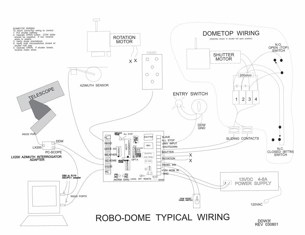
HAND
DDW FRONTPANEL SWITCH
DDW FRONTPANEL SWITCH
13VDC 4-6APOWER SUPPLY
ROBO-DOME TYPICAL WIRINGDDW3f
REV 030801
RS232 PORT
RS232 PORTS
DB9 to RJ14SBC/PC1 adapterDB9 to RJ14SBC/PC1 adapter
LX200
DDW
PC-SCOPE
LX200 AZIMUTH INTERROGATORADAPTER
LX200 AZIMUTH INTERROGATORADAPTER
ROTATIONMOTOR
SHUTTERMOTOR
AZIMUTH SENSOR
X
X
X X
N.O.OPEN (TOP)
SWITCH
N.C.CLOSED (BTTM)
SWITCH
200ohm
SLIDING CONTACTS
DDWGND
ENTRY SWITCH
DOMETOP WIRING
1 2 3 4
120VAC
DOMETOP WIRINGTo return DomeTop wiring to correct:1. Put shutter halfway2. Operate OPEN button. CCW slider
should be negative. If not, reversewires to sliders.
3. Verify diode orientations4. Verify both microswitches closed w/
shutter half way5. Operate OPEN. If shutter closes,
reverse motor wires.
TELESCOPE
(Switches shown in shutter full open position)
16
C7
7
DD
W3
MM
DD
YY 24
LC
-0
1B
24
LC
-0
1B
MA
X2
32
UL
N2
00
3
1
8
REV
SHUTTER
DDW3
GND
+12V NOM IN
PANEL SW
ROTATION
SHUTTER
SLAVE
UNIV INPUT
ALL STOP
SHUTDOWN
PC
LX200
AZ/HOME
HAND
I-L
USER I/O
WEATHER
FRPCFRPC
TOPCTOPC
DEFAULT/TRAINDEFAULT/TRAIN ALL STOP
HEARTBEAT/HOMEHEARTBEAT/HOME
(NORM GRN)
DIP1-8
LOCAL OFF REMOTE
DEADZONE0-15D
DEADZONE0-15D
OFFSETLX AZQUADAUTOPARK
ON OFF
DEFAULT
CKT BRK(RED=ON)
ES
CPOW TRANS
12V REG
SCHOTTKY
RUN
START DELAY