instructions for operation of test panel - s & c electric · instructions for operation of test...
TRANSCRIPT

Instructions for Operation of Test Panel
Section Page Section Page
Table of Contents
Introduction Qualified Persons . . . . . . . . . . . . . . . . . . . . . . . . . . . . . 2 Read this Instruction Sheet . . . . . . . . . . . . . . . . . . . . . . 2 Retain this Instruction Sheet . . . . . . . . . . . . . . . . . . . . . 2 Proper Application . . . . . . . . . . . . . . . . . . . . . . . . . . . . . 2Warranty . . . . . . . . . . . . . . . . . . . . . . . . . . . . . . . . . . . . 2General . . . . . . . . . . . . . . . . . . . . . . . . . . . . . . . . . . . . . 3
Safety Information Understanding Safety-Alert Messages . . . . . . . . . . . . . 4 Following Safety Instructions . . . . . . . . . . . . . . . . . . . . 4 Replacement Instructions and Labels . . . . . . . . . . . . . . 4
Metal-Enclosed Switchgear Application . . . . . . . . . . . . . . . . . . . . . . . . . . . . . . . . . . . 5
Loss-of-Source Testing . . . . . . . . . . . . . . . . . . . . . . . . . 6 Unbalance-Detection Testing . . . . . . . . . . . . . . . . . . . . 9 Overcurrent-Lockout Testing . . . . . . . . . . . . . . . . . . . 10 When Testing Is Completed . . . . . . . . . . . . . . . . . . . . 13
Pad-Mounted Gear Application . . . . . . . . . . . . . . . 14 Loss-of-Source Testing . . . . . . . . . . . . . . . . . . . . . . . . 15 Unbalance-Detection Testing . . . . . . . . . . . . . . . . . . . 19 Overcurrent-Lockout Testing . . . . . . . . . . . . . . . . . . . 20 When Testing Is Completed . . . . . . . . . . . . . . . . . . . . 21
Vista® Underground Distribution Switchgear Application . . . . . . . . . . . . . . . . . . . . . . . . . . . . . . . . . . 22
Loss-of-Source Testing . . . . . . . . . . . . . . . . . . . . . . . . 22 Unbalance-Detection Testing . . . . . . . . . . . . . . . . . . . 25 Overcurrent-Lockout Testing . . . . . . . . . . . . . . . . . . . 26 When Testing Is Completed . . . . . . . . . . . . . . . . . . . . 27
Weatherproof Enclosure Application . . . . . . . . . . . . . . . . . . . . . . . . . . . . . . . . . . 28
Loss-of-Source Testing . . . . . . . . . . . . . . . . . . . . . . . 28 Unbalance-Detection Testing . . . . . . . . . . . . . . . . . . . 32 Overcurrent-Lockout Testing . . . . . . . . . . . . . . . . . . . 33 When Testing Is Completed . . . . . . . . . . . . . . . . . . . . 34
Before Walking Away . . . . . . . . . . . . . . . . . . . . . . . . . 35
S&C Micro-AT® Source-Transfer Controls
Instruction Sheet 515-505June 30, 2008© S&C Electric Company
Introduction
Qualified Persons Ç WARNING
The equipment covered by this publication must be in stalled, operated, and main-tained by qualified persons who are knowledgeable in the installation, operation, and maintenance of electric power distribution equip ment along with the associated hazards. A qualified per son is one who is trained and competent in:
The skills and techniques necessary to distinguish exposed live parts from •non-live parts of electrical equipment.
The skills and techniques necessary to determine the proper approach distances •corresponding to the voltages to which the qualified person will be exposed.
The proper use of the special precautionary tech niques, personal protective •equipment, insulating and shielding materials, and insulated tools for working on or near exposed energized parts of electrical equipment.
These instructions are intended only for such qualified persons. They are not intended to be a substitute for ad equate training and experience in safety proce-dures for this type of equipment.
Read this Instruction Sheet
Thoroughly and carefully read this instruction sheet before operating your Micro-AT Source-Transfer Control. Familiarize yourself with “Safety Information” on page 4. The latest version is available online in PDF format at www.sandc.com. Select: Support/Product Literature Library.
Retain this Instruction Sheet
This instruction sheet should be available for reference wherever and whenever Micro-AT Source-Transfer Control is to be used. Retain this instruction sheet in a location where you can easily retrieve and refer to this publication.
Proper Application Ç CAUTION
The equipment in this publication must be selected for a specific application. The application must be within the ratings furnished for the equipment.
Warranty The warranty and/or obligations described in S&C’s standard conditions of sale, as set forth in Price Sheet 150, plus any special warranty provisions, as set forth in the applicable product-line specification bulletin, are exclusive. The remedies provided in the former for breach of these warranties shall constitute immediate purchaser’s or end user’s exclusive remedy and a fulfillment of all seller’s liability. In no event shall seller’s liability to immediate purchaser or end user exceed the price of the specific product which gives rise to immediate purchaser’s or end user’s claim. All other warranties whether express or implied or arising by operation of law, course of dealing, usage of trade or otherwise, are excluded. The only warranties are those stated in Price Sheet 150, and THERE ARE NO EXPRESS OR IMPLIED WARRANTIES OF MERCHANT-ABILITY OR FITNESS FOR A PARTICULAR PURPOSE. ANY EXPRESS WARRANTY OR OTHER OBLIGATION PROVIDED IN PRICE SHEET 150 IS GRANTED ONLY TO THE IMMEDIATE PURCHASER AND END USER, AS DEFINED THEREIN. OTHER THAN AN END USER, NO REMOTE PURCHASER MAY RELY ON ANY AFFIRMATION OF FACT OR PROMISE THAT RELATES TO THE GOODS DESCRIBED HEREIN, ANY DESCRIPTION THAT RELATES TO THE GOODS, OR ANY REMEDIAL PROMISE INCLUDED IN PRICE SHEET 150.
2 S&C Instruction Sheet 515-505

Introduction
General This publication provides instructions for use of the optional test panel feature for the Micro-AT Source-Trans fer Control (Catalog Number Suffix “-Y5”). See Figure 1. This feature permits the use of an external, adjustable three-phase source to verify, through independent mea surement, the response of the control to loss-of-source, phase- unbalance, and overcurrent-lockout conditions. If such a source is not available, limited testing may be per formed using an external, adjustable single-phase source.
S&C Test Accessory (Catalog Number TA-2669 in all applications) is required if the source-transfer control is to be tested with the switchgear de-energized, to provide con-trol power for the switch operators. Refer to the near est S&C Sales Office for availability of this device.
In instances where pad-mounted gear is to be tested using an external, adjustable three-phase source, an S&C Voltage Limiter—Three-Phase Catalog Number TA-1741 must be furnished. Again, refer to the nearest S&C Sales Office for availability of this device.
Refer to S&C Instruction Sheet 515-500 or 515-600 for instructions on field program-ming and operation of the Micro-AT Source-Transfer Control. Refer to S&C Instruc tion Sheet 515-510 for instructions on operation of the S&C Test Accessory.
Figure 1. Test panel.
S&C Instruction Sheet 515-505 3
Safety Information
Understanding Safety-Alert Messages
There are several types of safety-alert messages which may appear throughout this instruction sheet as well as on labels affixed to the gear. Familiarize yourself with these types of messages and the importance of the vari ous signal words, as explained below.
Ç DANGER
“DANGER” identifies the most serious and immediate hazards which will likely result in serious personal injury or death if instructions, including recommended precautions, are not followed.
Ç WARNING
“WARNING” identifies hazards or unsafe practices which can result in serious personal injury or death if instructions, including recommended precautions, are not followed.
Ç CAUTION
“CAUTION” identifies hazards or unsafe practices which can result in minor personal injury or product or property damage if instructions, including recommended precautions, are not followed.
NOTICE
“NOTICE” identifies important procedures or requirements that, if not followed, can result in product or property damage if instructions are not followed.
Following Safety Instructions
If you do not understand any portion of this instruction sheet and need assistance, contact your nearest S&C Sales Office or S&C Authorized Distributor, or call S&C Headquarters at (773) 338-1000, Monday through Friday between 8:30 AM and 5:00 PM Central Standard Time. (In Canada, call S&C Electric Canada Ltd. at (416) 249-9171, Monday through Friday between 8:00 AM and 5:00 PM Eastern Standard Time.)
NOTICE
Thoroughly and carefully read this instruction sheet before operating your Micro-AT Source-Transfer Control.
Replacement Instructions and Labels
If you need additional copies of this instruction sheet, contact your nearest S&C Sales Office, S&C Authorized Distributor, S&C Headquarters, or S&C Electric Canada Ltd.
It is important that any missing, damaged, or faded labels on the equipment be replaced immediately. Replacement labels are available by contacting your near est S&C Sales Office, S&C Authorized Distributor, S&C Headquarters, or S&C Electric Canada Ltd.
4 S&C Instruction Sheet 515-505

Metal-Enclosed Switchgear Application
The instructions which follow apply to S&C Metal-Enclosed Switchgear and presuppose that it has been installed in accordance with the applicable drawings, instruction sheets, and wiring diagrams, and is in all respects ready for operation. The metal-enclosed switch gear need not be energized and carrying current. But if the source-transfer control is to be tested with the switchgear de-energized, an S&C Test Accessory must be furnished to provide control power for the switch operators. In addi tion, if three-phase voltage sensing is provided by three S&C Indoor Voltage Sensors (Voltage-Sensing Arrange ment Catalog Number Suffix “-V3”), a separate 120-volt, 60-Hz source must be provided for the switch operators and Micro-AT Source-Transfer Control.
If any measurement made during the course of this procedure does not conform with the value specified, con sult the nearest S&C Sales Office.
Make certain that the doors of the entrance bays are fully closed to prevent the interlocks from jamming.
Ç CAUTION
Do not apply test voltage directly to the secondary circuits of the voltage sensing devices or the current sensors (if furnished).
Step 1 Place the manual/automatic operation selector switch in “MANUAL.”
Step 2 Since the loss-of-source and return-of-source level detec tor settings are dependent upon the positions of the source interrupter switches, it will be necessary to change switch positions during loss-of-source testing. Thus, decouple each switch operator from its interrupter switch—unless temporary service interruptions are per missible.
Step 3 Remove the input plug from the input receptacle and immediately transfer it to the shorting receptacle.
Ç CAUTION
Failure to immediately place the input plug on the shorting receptacle may result in damage to the voltage sensors and voltage limiters that will render the auto matic-transfer scheme inoperative.
This procedure short-circuits and isolates the secondaries of the voltage sensors, if furnished, and isolates the volt age transformers.
If the source-transfer control is to be tested with the switchgear de-energized: Plug the S&C Test Accessory into the input receptacle. Make up the connections to the test accessory as shown in S&C Instruction Sheet 515-510.
Step 4 Loosen the screw which retains the hinged lower panel of the source-transfer control and open the panel. See Figure 1.
Step 5 Place the external/normal selector switches on the test panel for the left source and the right source in “EXTER NAL.” See Figure 2 on page 7.
S&C Instruction Sheet 515-505 5

Metal-Enclosed Switchgear Application
Loss-of-Source Testing Step 6 For metal-enclosed switchgear furnished with three-phase voltage sensing:
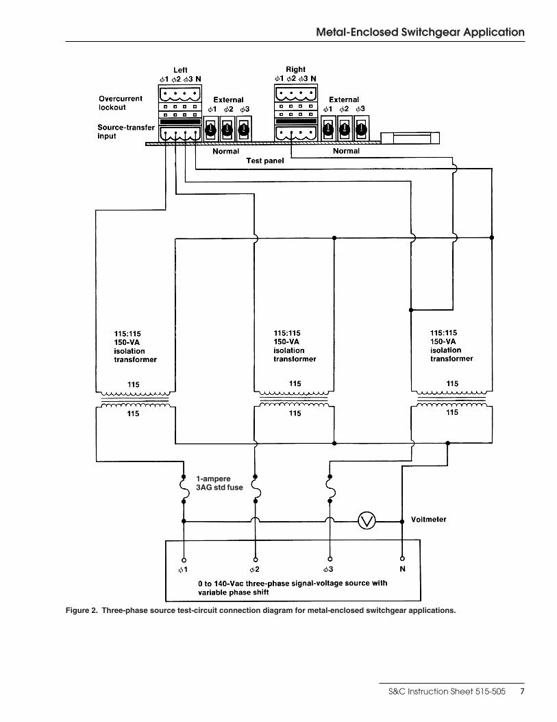
If a 0 to 140-volt, 60-Hz three-phase signal-voltage source with variable phase shift is available, make up the three-phase source test-circuit connections as shown in Figure 2 on page 7.
If a 0 to 140-volt, 60-Hz three-phase signal-voltage source with variable phase shift is not available, make up the single-phase source test-circuit connections as shown in Figure 3 on page 8. This test circuit cannot be used to test operation of the unbalance detection feature in response to a phase-angle unbalance.
Proceed to Step 8.
Step 7 For metal-enclosed switchgear furnished with single-phase voltage sens-ing: Make up the single-phase source test-circuit connections to phase 2 and neutral on the left source-transfer input connector and to phase 2 on the right source-transfer input connector as shown in Figure 3 on page 8.
Step 8 If, through independent measurement, the output voltage of a voltage trans-former on phase 2 of the system is known, energize the signal-voltage source and adjust the signal voltage on all three phases to that known voltage. Otherwise, energize the signal-voltage source and adjust the signal voltage on all three phases to 120 volts ac.
For metal-enclosed switchgear furnished with single-phase voltage sensing, proceed to Step 11.
Step 9 Turn off unbalance detect.
(a) Press the “CONFIGURE” menu key.
(b) Press the “NEXT” item key (or the “LAST” item key) repeatedly until unbalance detect is displayed. Then press the “CHANGE” key.
(c) Press each digit of the access code number, then press the “ENTER” key.
(d) Press the “ ” or “ ” key to change the response to “OFF.” Then press the “ENTER” key.
Step 10 Normalize the left source.
(a) Press the “CONFIGURE” menu key.
(b) Press the “NEXT” item key (or the “LAST” item key) repeatedly until normalize left is displayed. Then press the “CHANGE” key.
(c) Press each digit of the access code number, then press the “ENTER” key.
(d) Press the “ENTER” key again to normalize.
Step 11 If, through independent measurement, the output voltage of a voltage trans-former on phase 2 of the system is known, set the left-source base voltage to that known value. Otherwise, set the left-source base voltage to 120 volts ac.
(a) Press the “CONFIGURE” menu key.
(b) Press the “NEXT” item key (or “Last” item key) repeatedly until set base left is displayed; the value shown is the present phase 2 base voltage. Base volt age may be field adjusted over the range of 105 to 130 volts. If a change to the base voltage is desired, pro ceed to (c). Otherwise, proceed to Step 12.
(c) Press the “CHANGE” key.
(d) Press each digit of the access-code number, then press the “ENTER” key.
(e) Press the number keys corresponding to the desired value. Then press the “ENTER” key.
6 S&C Instruction Sheet 515-505
1-ampere 3AG std fuse
Metal-Enclosed Switchgear Application
Figure 2. Three-phase source test-circuit connection diagram for metal-enclosed switchgear applications.
S&C Instruction Sheet 515-505 7
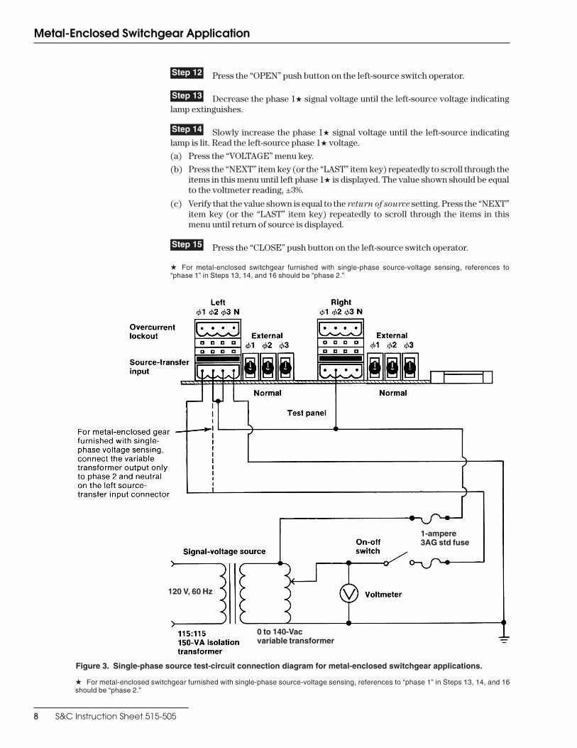
Figure 3. Single-phase source test-circuit connection diagram for metal-enclosed switchgear applications.
120 V, 60 Hz
1-ampere 3AG std fuse
0 to 140-Vac variable transformer
Metal-Enclosed Switchgear Application
Step 12 Press the “OPEN” push button on the left-source switch operator.
Step 13 Decrease the phase 1w signal voltage until the left-source voltage indicating lamp extinguishes.
Step 14 Slowly increase the phase 1w signal voltage until the left-source indicating lamp is lit. Read the left-source phase 1w voltage.
(a) Press the “VOLTAGE” menu key.
(b) Press the “NEXT” item key (or the “LAST” item key) repeatedly to scroll through the items in this menu until left phase 1w is displayed. The value shown should be equal to the voltmeter reading, ±3%.
(c) Verify that the value shown is equal to the return of source setting. Press the “NEXT” item key (or the “LAST” item key) repeatedly to scroll through the items in this menu until return of source is displayed.
Step 15 Press the “CLOSE” push button on the left-source switch operator.
w For metal-enclosed switchgear furnished with single-phase source-voltage sensing, references to “phase 1” in Steps 13, 14, and 16 should be “phase 2 .”
w For metal-enclosed switchgear furnished with single-phase source-voltage sensing, references to “phase 1” in Steps 13, 14, and 16 should be “phase 2 .”
8 S&C Instruction Sheet 515-505

Metal-Enclosed Switchgear Application
Step 16 Slowly decrease the phase 1w signal voltage until the left-source voltage indicating lamp extinguishes. Read the left-source phase 1w voltage.
(a) Press the “VOLTAGE” menu key.
(b) Press the “NEXT” item key (or the “LAST” item key) repeatedly to scroll through the items in this menu until left phase 1w is displayed. The value shown should be equal to the voltmeter reading, ±3%.
(c) Verify that the value shown is equal to the loss of source setting. Press the “NEXT” item key (or the “LAST” item key) repeatedly to scroll through the items in this menu until return of source is displayed.
Step 17 For metal-enclosed switchgear furnished with three-phase voltage sensing: If the three-phase source test circuit shown in Figure 2 on page 7 is used, repeat Steps 12 through 16 for phase 2 and then for phase 3.
If the single-phase source test circuit shown in Figure 3 is used, repeat Steps 12 through 16 for phase 2 and then for phase 3. When inputting signal voltage to phase 2, de-energize the signal-voltage source and jumper phases 1 and 3 of the left source- transfer input connector (instead of phases 2 and 3 as shown in Figure 3 on page 8); then energize the signal-voltage source. When inputting signal voltage to phase 3, de-energize the signal-voltage source and jumper phases 1 and 2 of the left source-transfer input connector; then energize the signal-voltage source.
For metal-enclosed switchgear furnished with single-phase voltage sensing, proceed to Step 24.
Unbalance-Detection Testing
This testing can be performed only if the three-phase source test circuit shown in Figure 2 on page 7 is used. If a single-phase source test circuit is used, proceed to Step 24.
Step 18 Adjust the three-phase voltage source for a nominal 120-degree phase angle between each phase.
Step 19 Turn on unbalance detect.
(a) Press the “CONFIGURE” menu key.
(b) Press the “NEXT” item key (or the “LAST” item key) repeatedly until unbalance detect is displayed. Then press the “CHANGE” key.
(c) Press each digit of the access code number, then press the “ENTER” key.
(d) Press the “ ” or “ ” key to change the response to “OFF.” Then press the “ENTER” key.
Step 20 With the left-source switch operator in the closed posi tion, slowly decrease the phase 1 signal voltage until the left-source voltage indicating lamp extinguishes. Read the left-source unbalance voltage.
(a) Press the “VOLTAGE” menu key.
(b) Press the “NEXT” item key (or the “LAST” item key) repeatedly to scroll through the items in this menu until left unbalance is displayed. The value shown should be equal to the voltmeter reading, ±3%.
(c) Verify that the value shown is equal to the unbalance detect setting. Press the “NEXT” item key (or the “LAST” item key) repeatedly to scroll through the items in this menu until unbalance detect is dis played.
w For metal-enclosed switchgear furnished with single-phase source-voltage sensing, references to “phase 1” in Steps 13, 14, and 16 should be “phase 2 .”
S&C Instruction Sheet 515-505 9

Metal-Enclosed Switchgear Application
Step 21 Slowly change the phase angle of phase 1 in the positive direction until the left-source voltage indicating lamp extinguishes. Read the phase angle on the signal-voltage source. The value shown should be approximately +8.6 degrees if a 120-volt base is used and the unbalance detect factory-setting of 18 volts is used. (If a different base volt age and/or unbalance detect setting is used, the phase angle value should be approxi-mately equal to sin-1 [unbal ance detect setting/base voltage].) Return the phase angle of phase 1 to its nominal 120-degree setting.
Step 22 Slowly change the phase angle of phase 1 in the negative direction until the left-source voltage indicating lamp extinguishes. Read the phase angle on the signal-voltage source. The value shown should be approximately –8.6 degrees if a 120-volt base is used and the unbalance detect factory-setting of 18 volts is used. (If a different base volt age and/or unbalance detect setting is used, the phase angle value shown should be approximately equal to –sin-1 [unbalance detect setting/base voltage].) Return the phase angle of phase 1 to its nominal 120-degree setting.
Step 23 Repeat Steps 20 through 22 for phase 2 and then for phase 3.
Step 24 De-energize the signal-voltage source. Reverse the test cir cuit connections to the left and right source-transfer input connectors and repeat Steps 8 through 17 for the right source.
Step 25 If a single-phase source test circuit is used, proceed to Step 26.
Repeat Steps 18 through 23 for the right source.
Overcurrent-Lockout Testing
This testing can be performed only if lockout option has been selected and current sen-sors have been installed on the sources.
Step 26 Verify that lockout option has been selected.
(a) Press the “CONFIGURE” menu key.
(b) Press the “NEXT” item key (or the “LAST” item key) repeatedly until lockout option is displayed.
(c) If the response is “OUT,” proceed to Step 33. If the response is “IN,” proceed to Step 27.
Step 27 Make up the test circuit connections to phase 1 and neu tral on the left over-current-lockout connector and to phase 2 on the left source-transfer input connector as shown in Figure 4 on page 12.
10 S&C Instruction Sheet 515-505
Metal-Enclosed Switchgear Application
Step 28 Set the variable transformer for zero volts. Energize the isolation transformer and slowly increase the signal volt age until the “LOCKOUT” lamp is lit. Read the signal volt age on the voltmeter.
If S&C Closed-Gap Current Sensors are utilized, the value shown should be approxi-mately 21.1 volts if the lockout level factory-setting of 1200 amperes is used. (If a differ-ent lockout level setting is used, the value shown should be approximately equal to [lockout level/57 amperes per volt].) The presence of load current can sig nificantly affect this measurement.
If superseded-design open-gap S&C Current Sensors are utilized (as would be the case if the Micro-AT Source-Transfer Control replaces an obsolete S&C Type AT-2 or Type AT-3 Source-Transfer Control), the value shown should be approximately 4.6 volts if the lockout level factory-setting of 1200 amperes is used. (If a differ ent lockout level setting is used, the value shown should be approximately equal to [lockout level/ 263.2 amperes per volt].) The presence of load current can significantly affect this measurement.
Step 29 Press the “RESET” key. The “LOCKOUT” lamp will extin guish.
Decrease the signal voltage by 10%.
Step 30 De-energize the signal-voltage source. Make up the test-circuit connections to phase 2 and neutral on the left over current-lockout connector and to phase 2 on the left source-transfer input connector. Then repeat Steps 28 and 29. De-energize the signal-voltage source. Make up the test-circuit connections to phase 3 and neutral on the left overcurrent-lockout connector and to phase 2 on the left source-transfer input connec-tor. Then repeat Steps 28 and 29.
Step 31 De-energize the signal-voltage source. Make up the test-circuit connections to phase 1 and neutral on the right overcurrent-lockout connector and to phase 2 on the right source-transfer input connector. Then repeat Steps 28 and 29.
Step 32 De-energize the signal-voltage source. Make up the test-circuit connections to phase 2 and neutral on the right overcurrent-lockout connector and to phase 2 on the right source-transfer input connector. Then repeat Steps 28 and 29. De-energize the signal-voltage source. Make up the test-circuit connections to phase 3 and neutral on the right overcurrent-lockout connector and to phase 2 on the right source-transfer input connector. Then repeat Steps 28 and 29.
S&C Instruction Sheet 515-505 11

Metal-Enclosed Switchgear Application
Figure 4. Overcurrent-lockout test-circuit connection diagram for metal-enclosed switchgear applications.
120 V, 60 Hz
1-ampere 3AG std fuse
0 to 140-Vac variable transformer
12 S&C Instruction Sheet 515-505
Metal-Enclosed Switchgear Application
When Testing Is Completed
Step 33 De-energize the signal-voltage source and remove the test-circuit connections.
Step 34 Place the external/normal selector switches for the left source and for the right source in “NORMAL.”
Step 35 De-energize the connections to the test accesory, if appli cable. Then unplug the test accessory from the input receptacle of the source-transfer control. Remove the input plug from the shorting receptacle and immediately transfer it to the input recep-tacle. Recouple each switch operator to its interrupter switch.
Ç CAUTION
Failure to immediately place the input plug on the input receptacle may result in dam-age to the voltage sensors and voltage limiters that will render the automatic-transfer scheme inoperative.
Step 36 If the switchgear is energized, repeat Steps 10 and 11 for the known normal system state. Repeat Steps 10 and 11 for the right source.
Please see “Before Walking Away” on page 35.
S&C Instruction Sheet 515-505 13

Pad-Mounted Gear Application
The instructions which follow apply to S&C Source-Trans fer Pad-Mounted Gear and pre-suppose that it has been installed in accordance with the applicable drawings, instruc-tion sheets, and wiring diagrams, and is in all respects ready for operation. The pad-mounted gear need not be energized and carrying current. But if voltage sens ing is provided by three 14.4-kV S&C Indoor Voltage Sen sors applied at 4.16 kV (Voltage-Sens-ing Arrangement Catalog Number Suffix “-V2”), a separate 120-volt, 60-Hz source must be provided for the switch operators and Micro-AT Source-Transfer Control.
If any measurement made during the course of this procedure does not conform with the value specified, con sult the nearest S&C Sales Office.
If the pad-mounted gear is equipped with optional mechanical cable interlocks (Cata-log Number Suffix “-C6” or “-C16”), make certain that the switch-compartment doors are fully closed to prevent the interlocks from jam ming.
Ç CAUTION
Do not apply test voltage directly to the secondary circuits of the voltage sensors or the current sensors (if furnished).
Step 1 Place the manual/automatic operation selector switch in “MANUAL.”
Step 2 Since the loss-of-source and return-of-source level detec tor settings are dependent upon the positions of the source interrupter switches, it will be necessary to change switch positions during loss-of-source testing. Thus, decouple each switch oper-ator from its interrupter switch—unless temporary service interruptions are per-missible.
Step 3 Remove the bolted cover which provides access to the input plug and short-ing receptacle for the Micro-AT con trol. Remove the input plug from the input receptacle and immediately transfer it to the shorting receptacle.
Ç CAUTION
Failure to immediately place the input plug on the shorting receptacle may result in damage to the voltage sensors and voltage limiters that will render the auto matic-transfer scheme inoperative.
This procedure short-circuits and isolates the second aries of the voltage sensors and also isolates the current sensors utilized with the optional overcurrent-lockout fea ture, if furnished.
Step 4 Loosen the screw which retains the hinged lower panel of the source-transfer control and open the panel. See Figure 1 on page 4.
Step 5 Place the external/normal selector switches on the test panel for the left source and the right source in “EXTER NAL.” See Figure 5 on page 16.
14 S&C Instruction Sheet 515-505

Pad-Mounted Gear Application
Loss-of-Source Testing Step 6 If a 0 to 140-volt, 60-Hz three-phase signal-voltage source with variable phase shift is available, make up the three-phase source test-circuit connections as shown in Figure 5 on page 16.
If a 0 to 140-volt, 60-Hz three-phase signal-voltage source with variable phase shift is not available, make up the single-phase source test-circuit connections as shown in Figure 6 on page 17. This test circuit cannot be used to verify signal-voltage calibration on phase 2, nor can it be used to test operation of the unbalance detection fea ture in response to a phase-angle unbalance.
Step 7 If, through independent measurement, the output voltage of a voltage trans-former on phase 2 of the system is known, energize the signal-voltage source and adjust the signal voltage on all three phases to that known voltage. Otherwise, energize the sig-nal-voltage source and adjust the signal voltage on all three phases to 120 volts ac.
Step 8 Turn off unbalance detect.
(a) Press the “CONFIGURE” menu key.
(b) Press the “NEXT” item key (or the “LAST” item key) repeatedly until unbalance detect is displayed. Then press the “CHANGE” key.
(c) Press each digit of the access code number, then press the “ENTER” key.
(d) Press the “ ” or “ ” key to change the response to “OFF.” Then press the “ENTER” key.
S&C Instruction Sheet 515-505 15

Ç DANGERHigh voltage (approxi-mately 670 volts) is present across the sec ondary windings of the phase 2 isolation trans formers. Make certain that the secondary windings are connected to the S&C Voltage Limiter at all times and that the entire circuit is properly covered.
Figure 5. Three-phase source test-circuit connection diagram for source-transfer pad-mounted gear applications.
1-ampere 3AG std fuse
0 to 140-Vac three-phase signal-voltage source with variable phase shift
Pad-Mounted Gear Application
16 S&C Instruction Sheet 515-505

Figure 6. Single-phase source test-circuit connection diagram for source-transfer pad-mounted gear applications.
120 V, 60 Hz
1-ampere 3AG std fuse
0 to 140-Vac variable transformer
Pad-Mounted Gear Application
Step 9 Normalize the left source.
(a) Press the “CONFIGURE” menu key.
(b) Press the “NEXT” item key (or the “LAST” item key) repeatedly until normalize left is displayed. Then press the “CHANGE” key.
(c) Press each digit of the access code number, then press the “ENTER” key.
(d) Press the “ENTER” key again to normalize.
Step 10 If, through independent measurement, the output voltage of a voltage trans-former on phase 2 of the system is known, set the left-source base voltage to that known voltage. Otherwise, set the left-source base voltage to 120 volts ac.
(a) Press the “CONFIGURE” menu key.
(b) Press the “NEXT” item key (or the “LAST” item key) repeatedly until set base left is displayed; the value shown is the present phase 2 base voltage. Base volt age may be field adjusted over the range of 105 to 130 volts. If a change to the base voltage is desired, pro ceed to (c). Otherwise, proceed to Step 11.
(c) Press the “CHANGE” key.
(d) Press each digit of the access-code number, then press the “ENTER” key.
(e) Press the number keys corresponding to the desired value. Then press the “ENTER” key.
S&C Instruction Sheet 515-505 17

Pad-Mounted Gear Application
Step 11 Press the “OPEN” push button on the left-source switch operator.
Step 12 Decrease the phase 1 signal voltage until the left-source voltage indicating lamp extinguishes.
Step 13 Slowly increase the phase 1 signal voltage until the left-source voltage indi-cating lamp is lit. Read the left-source phase 1 voltage.
(a) Press the “VOLTAGE” menu key.
(b) Press the “NEXT” item key (or the “LAST” item key) repeatedly to scroll through the items in this menu until left phase 1 is displayed. The value shown should be equal to the voltmeter reading, ±3%.
(c) Verify that the value shown is equal to the return of source setting. Press the “NEXT” item key (or the “LAST” item key) repeatedly to scroll through the items in this menu until return of source is displayed.
Step 14 Press the “CLOSE” push button on the left-source switch operator.
Step 15 Slowly decrease the phase 1 signal voltage until the left-source voltage indi-cating lamp extinguishes. Read the left-source phase 1 voltage.
(a) Press the “VOLTAGE” menu key.
(b) Press the “NEXT” item key (or the “LAST” item key) repeatedly to scroll through the items in this menu until left phase 1 is displayed. The value shown should be equal to the voltmeter reading, ±3%.
(c) Verify that the value shown is equal to the loss of source setting. Press the “NEXT” item key (or “LAST” item key) repeatedly to scroll through the items in this menu until return of source is displayed.
Step 16 If the three-phase source test circuit shown in Figure 5 on page 16 is used, repeat Steps 11 through 15 for phase 2 and then for phase 3.
If the single-phase source test circuit shown in Figure 6 on page 17 is used, repeat Steps 11 through 15 for phase 3 only since the single-phase source test circuit cannot verify signal-voltage calibration of the voltage sensor on phase 2. When inputting signal voltage to phase 3, de-energize the signal-voltage source and jumper phases 1 and 2 of the left source-transfer input connector (instead of phases 2 and 3 as shown in Figure 6); then energize the signal-voltage source.
18 S&C Instruction Sheet 515-505

Pad-Mounted Gear Application
Unbalance-Detection Testing
This testing can be performed only if the three-phase source test circuit shown in Figure 5 is used. If a single-phase source test circuit is used, proceed to Step 22.
Step 17 Adjust the three-phase voltage source for a nominal 120-degree phase angle between each phase.
Step 18 Turn on unbalance detect.
(a) Press the “CONFIGURE” menu key.
(b) Press the “NEXT” item key (or the “LAST” item key) repeatedly until unbalance detect is displayed. Then press the “CHANGE” key.
(c) Press each digit of the access code number, then press the “ENTER” key.
(d) Press the “ ” or “ ” key to change the response to “OFF.” Then press the “ENTER” key.
Step 19 With the left-source switch operator in the closed posi tion, slowly change the phase angle of phase 1 in the posi tive direction until the left-source voltage indicating lamp extinguishes. Read the phase angle on the signal-voltage source. The value shown should be approximately +14.3 degrees if a 120-volt base is used and the unbalance detect factory-setting of 30 volts is used. (If a different base volt age and/or unbalance detect setting is used, the phase angle value shown should be approximately equal to sin-1 [unbalance detect setting/base voltage].) Return the phase angle of phase 1 to its nominal 120-degree setting.
Step 20 Slowly change the phase angle of phase 1 in the negative direction until the left-source voltage indicating lamp extinguishes. Read the phase angle on the signal-voltage source. The value shown should be approximately –14.3 degrees if a 120-volt base is used and the unbalance detect factory-setting of 30 volts is used. (If a different base volt age and/or unbalance detect setting is used, the phase angle value shown should be approximately equal to –sin-1 [unbalance detect setting/base voltage].) Return the phase angle of phase 1 to its nominal 120-degree setting.
Step 21 Repeat Steps 19 and 20 for phase 2 and then for phase 3.
Step 22 De-energize the signal-voltage source. Reverse the test cir cuit connections to the left and right source-transfer input connectors and repeat Steps 7 through 16 for the right source.
Step 23 If a single-phase source test circuit is used, proceed to Step 24.
Repeat Steps 17 through 21 for the right source.
S&C Instruction Sheet 515-505 19
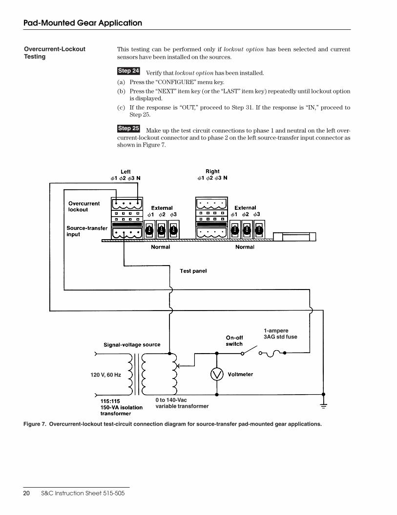
Figure 7. Overcurrent-lockout test-circuit connection diagram for source-transfer pad-mounted gear applications.
120 V, 60 Hz
1-ampere 3AG std fuse
0 to 140-Vac variable transformer
Pad-Mounted Gear Application
Overcurrent-Lockout Testing
This testing can be performed only if lockout option has been selected and current sensors have been installed on the sources.
Step 24 Verify that lockout option has been installed.
(a) Press the “CONFIGURE” menu key.
(b) Press the “NEXT” item key (or the “LAST” item key) repeatedly until lockout option is displayed.
(c) If the response is “OUT,” proceed to Step 31. If the response is “IN,” proceed to Step 25.
Step 25 Make up the test circuit connections to phase 1 and neu tral on the left over-current-lockout connector and to phase 2 on the left source-transfer input connector as shown in Figure 7.
20 S&C Instruction Sheet 515-505

Pad-Mounted Gear Application
Step 26 Set the variable transformer for zero volts. Energize the isolation transformer and slowly increase the signal volt age until the “LOCKOUT” lamp is lit. Read the signal volt age on the voltmeter.
If S&C Closed-Gap Current Sensors are utilized, the value shown should be approxi-mately 18.8 volts if the lockout level factory-setting of 1200 amperes is used. (If a differ-ent lockout level setting is used, the value shown should be approximately equal to [lockout level/64 amperes per volt].)
If superseded-design open-gap S&C Current Sensors are utilized (as would be the case if the Micro-AT Source-Transfer Control replaces an obsolete S&C Type AT-12 Source-Transfer Control), the value shown should be approximately 2.4 volts if the lock-out level factory-set ting of 1200 amperes is used. (If a different lockout level setting is used, the value shown should be approximately equal to [lockout level/510.2 amperes per volt].)
Decrease the signal voltage by 10%.
Step 27 Press the “RESET” key. The “LOCKOUT” lamp will extinguish.
Step 28 De-energize the signal-voltage source. Make up the test-circuit connections to phase 2 and neutral on the left over current-lockout connector and to phase 2 on the left source-transfer input connector. Then repeat Steps 26 and 27. De-energize the signal-voltage source. Make up the test-circuit connections to phase 3 and neutral on the left overcurrent-lockout connector and to phase 2 on the left source-transfer input connec-tor. Then repeat Steps 26 and 27.
Step 29 De-energize the signal-voltage source. Make up the test-circuit connections to phase 1 and neutral on the right overcurrent-lockout connector and to phase 2 on the right source-transfer input connector. Then repeat Steps 26 and 27.
Step 30 De-energize the signal-voltage source. Make up the test-circuit connections to phase 2 and neutral on the right overcurrent-lockout connector and to phase 2 on the right source-transfer input connector. Then repeat Steps 26 and 27. De-energize the sig-nal-voltage source. Make up the test-circuit connections to phase 3 and neutral on the right overcurrent-lockout connector and to phase 2 on the right source-transfer input connector. Then repeat Steps 26 and 27.
When Testing Is Completed
Step 31 De-energize the signal-voltage source and remove the test-circuit connec-tions.
Step 32 Place the external/normal selector switches for the left source and for the right source in “NORMAL.”
Step 33 Remove the input plug from the shorting receptacle and immediately transfer it to the input receptacle. Recouple each switch operator to its interrupter switch.
Ç CAUTION
Failure to immediately place the input plug on the input receptacle may result in damage to the voltage sensors and voltage limiters that will render the automatic-transfer scheme inoperative.
Step 34 If the pad-mounted gear is energized, repeat Steps 9 and 10 for the known normal system state. Repeat Steps 9 and 10 for the right source.
Please see “Before Walking Away” on page 35.
S&C Instruction Sheet 515-505 21

Vista Underground Distribution Switchgear Application
The instructions which follow apply to S&C Source-Trans fer Vista UDS and presuppose that it has been installed in accordance with the applicable drawings, instruction sheets, and wiring diagrams, and is in all respects ready for operation. If the source-transfer control is to be tested with the switchgear de-energized, an S&C Test Accessory must be furnished to provide control power for the motor operators, switch controls, and Micro-AT Source-Transfer Control.
If any measurement made during the course of this procedure does not conform with the value specified, con sult the nearest S&C Sales Office.
Ç CAUTION
Do not apply test voltage directly to the secondary circuits of the voltage sensing devices or the current sensors (if furnished).
Step 1 Place the manual/automatic operation selector switch in “MANUAL.”
Step 2 Since the loss-of-source and return-of-source level detec tor settings are dependent upon the positions of the load-interrupter switches, it will be necessary to change switch positions during loss-of-source testing. Thus, remove each motor opera-tor from its interrupter switch—unless tem porary service interruptions are permissible.
Step 3 Remove the input plug from the input receptacle.
This procedure isolates the voltage sensors and the voltage transformers.
If the source-transfer control is to be tested with the switchgear de-energized: Plug the S&C Test Accessory into the input receptacle. Make up the connections to the test accessory as shown in S&C Instruction Sheet 515-510.
Step 4 Loosen the screw which retains the hinged lower panel of the source-transfer control and open the panel. See Figure 1 on page 4.
Step 5 Place the external/normal selector switches on the test panel for the left source and the right source in “EXTER NAL.” See Figure 8 on page 23.
Loss-of-Source Testing Step 6 If a 0 to 140-volt, 60-Hz three-phase signal-voltage source with variable phase shift is available, make up the three-phase source test-circuit connections as shown in Figure 8 on page 23.
If a 0 to 140-volt, 60-Hz three-phase signal-voltage source with variable phase shift is not available, make up the single-phase source test-circuit connections as shown in Figure 9 on page 24. This test circuit cannot be used to test operation of the unbalance detection feature in response to a phase-angle unbalance.
Step 7 If, through independent measurement, the output voltage of a voltage trans-former on phase 2 of the system is known, energize the signal-voltage source and adjust the signal voltage on all three phases to that known voltage. Otherwise, energize the sig-nal-voltage source and adjust the signal voltage on all three phases to 120 volts ac.
Step 8 Turn off unbalance detect.
(a) Press the “CONFIGURE” menu key.
(b) Press the “NEXT” item key (or the “LAST” item key) repeatedly until unbalance detect is displayed. Then press the “CHANGE” key.
(c) Press each digit of the access code number, then press the “ENTER” key.
(d) Press the “ ” or “ ” key to change the response to “OFF.” Then press the “ENTER” key.
22 S&C Instruction Sheet 515-505

Figure 8. Three-phase source test-circuit connection diagram for Vista UDS applications.
1-ampere 3AG std fuse
10-ampere 3AG std fuse
1-ampere 3AG std fuse
0 to 140-Vac three-phase signal-voltage source with variable phase shift
Vista Underground Distribution Switchgear Application
S&C Instruction Sheet 515-505 23

Figure 9. Single-phase source test-circuit connection diagram for Vista UDS applications.
10-ampere 3AG std fuse
120 V, 60 Hz
0 to 140-Vac variable transformer
Step 9 Normalize the left source.
(a) Press the “CONFIGURE” menu key.
(b) Press the “NEXT” item key (or the “LAST” item key) repeatedly until normalize left is displayed. Then press the “CHANGE” key.
(c) Press each digit of the access code number, then press the “ENTER” key.
(d) Press the “ENTER” key again to normalize.
Step 10 If, through independent measurement, the output voltage of a voltage trans-former on phase 2 of the system is known, set the left-source base voltage to that known value. Otherwise, set the left-source base voltage to 120 volts ac.
(a) Press the “CONFIGURE” menu key.
(b) Press the “NEXT” item key (or the “LAST” item key) repeatedly until set base left is displayed; the value shown is the present phase 2 base voltage. Base volt age may be field adjusted over the range of 105 to 130 volts. If a change to the base voltage is desired, pro ceed to (c). Otherwise, proceed to Step 11.
(c) Press the “CHANGE” key.
(d) Press each digit of the access-code number, then press the “ENTER” key.
(e) Press the number keys corresponding to the desired value. Then press the “ENTER” key.
Vista Underground Distribution Switchgear Application
24 S&C Instruction Sheet 515-505

Step 11 Press the “OPEN” push button on the left-source switch operator.
Step 12 Decrease the phase 1 signal voltage until the left-source voltage indicating lamp extinguishes.
Step 13 Slowly increase the phase 1 signal voltage until the left-source indicating lamp is lit. Read the left-source phase 1 voltage.
(a) Press the “VOLTAGE” menu key.
(b) Press the “NEXT” item key (or the “LAST” item key) repeatedly to scroll through the items in this menu until left phase 1 is displayed. The value shown should be equal to the voltmeter reading, ±3%.
(c) Verify that the value shown is equal to the return of source setting. Press the “NEXT” item key (or the “LAST” item key) repeatedly to scroll through the items in this menu until return of source is displayed.
Step 14 Press the “CLOSE” push button on the left-source switch operator.
Step 15 Slowly decrease the phase 1 signal voltage until the left-source voltage indicating lamp extinguishes. Read the left-source phase 1 voltage.
(a) Press the “VOLTAGE” menu key.
(b) Press the “NEXT” item key (or the “LAST” item key) repeatedly to scroll through the items in this menu until left phase 1 is displayed. The value shown should be equal to the voltmeter reading, ±3%.
(c) Verify that the value shown is equal to the loss of source setting. Press the “NEXT” item key (or the “LAST” item key) repeatedly to scroll through the items in this menu until return of source is displayed.
Step 16 If the three-phase source test circuit shown in Figure 8 on page 23 is used, repeat Steps 11 through 15 for phase 2 and then for phase 3.
If the single-phase source test circuit shown in Figure 9 on page 24 is used, repeat Steps 11 through 15 for phase 2 and then for phase 3. When inputting signal voltage to phase 2, de-energize the signal-voltage source and jumper phases 1 and 3 of the left source-transfer input connector (instead of phases 2 and 3 as shown in Figure 3 on page 8); then energize the signal-voltage source. When inputting signal voltage to phase 3, de-energize the signal-voltage source and jumper phases 1 and 2 of the left source-transfer input connector; then energize the signal-voltage source.
Unbalance-Detection Testing
This testing can be performed only if the three-phase source test circuit shown in Figure 8 on page 23 is used. If a single-phase source test circuit is used, proceed to Step 23.
Step 17 Adjust the three-phase voltage source for a nominal 120-degree phase angle between each phase.
Step 18 Turn on unbalance detect.
(a) Press the “CONFIGURE” menu key.
(b) Press the “NEXT” item key (or the “LAST” item key) repeatedly until unbalance detect is displayed. Then press the “CHANGE” key.
(c) Press each digit of the access code number, then press the “ENTER” key.
(d) Press the “ ” or “ ” key to change the response to “OFF.” Then press the “ENTER” key.
Vista Underground Distribution Switchgear Application
S&C Instruction Sheet 515-505 25

Step 19 With the left-source motor operator in the closed position, slowly decrease the phase 1 signal voltage until the left-source voltage indicating lamp extinguishes. Read the left-source unbalance voltage.
(a) Press the “VOLTAGE” menu key.
(b) Press the “NEXT” item key (or the “LAST” item key) repeatedly to scroll through the items in this menu until left unbalance is displayed. The value shown should be equal to the voltmeter reading, ±3%.
(c) Verify that the value shown is equal to the unbalance detect setting. Press the “NEXT” item key (or the “LAST” item key) repeatedly to scroll through the items in this menu until unbalance detect is dis played.
Step 20 Slowly change the phase angle of phase 1 in the positive direction until the left-source voltage indicating lamp extinguishes. Read the phase angle on the signal-voltage source. The value shown should be approximately +8.6 degrees if a 120-volt base is used and the unbalance detect factory-setting of 18 volts is used. (If a different base volt age and/or unbalance detect setting is used, the phase angle value should be approxi-mately equal to sin-1 [unbal ance detect setting/base voltage].) Return the phase angle of phase 1 to its nominal 120-degree setting.
Step 21 Slowly change the phase angle of phase 1 in the negative direction until the left-source voltage indicating lamp extinguishes. Read the phase angle on the signal-voltage source. The value shown should be approximately –8.6 degrees if a 120-volt base is used and the unbalance detect factory-setting of 18 volts is used. (If a different base volt age and/or unbalance detect setting is used, the phase angle value shown should be approximately equal to –sin-1 [unbalance detect setting/base voltage].) Return the phase angle of phase 1 to its nominal 120-degree setting.
Step 22 Repeat Steps 19 through 21 for phase 2 and then for phase 3.
Step 23 De-energize the signal-voltage source. Reverse the test cir cuit connections to the left and right source-transfer input connectors and repeat Steps 7 through 16 for the right source.
Step 24 If a single-phase source test circuit is used, proceed to Step 25.
Repeat Steps 17 through 22 for the right source.
Overcurrent-Lockout Testing
This testing can be performed only if lockout option has been selected and current sensors have been installed on the sources.
Step 25 Verify that lockout option has been selected.
(a) Press the “CONFIGURE” menu key.
(b) Press the “NEXT” item key (or the “LAST” item key) repeatedly until lockout option is displayed.
(c) If the response is “OUT,” proceed to Step 32. If the response is “IN,” proceed to Step 26.
Step 26 Make up the test circuit connections to phase 1 and neu tral on the left over-current-lockout connector and to phase 2 on the left source-transfer input connector as shown in Figure 10 on page 27.
Step 27 Set the variable transformer for zero volts. Energize the isolation transformer and slowly increase the signal volt age until the “LOCKOUT” lamp is lit. Read the signal volt age on the voltmeter.
The value shown should be approximately 4.6 volts if the lockout level factory-setting of 1200 amperes is used. (If a different lockout level setting is used, the value shown should be approximately equal to [lockout level/263.2 amperes per volt].) The presence of load current can significantly affect this measurement.
Decrease the signal voltage by 10%.
Vista Underground Distribution Switchgear Application
26 S&C Instruction Sheet 515-505

Figure 10. Overcurrent-lockout test-circuit connection diagram for Vista UDS applications.
Step 28 Press the “RESET” key. The “LOCKOUT” lamp will extin guish.
Step 29 De-energize the signal-voltage source. Make up the test-circuit connections to phase 2 and neutral on the left over current-lockout connector and to phase 2 on the left source-transfer input connector. Then repeat Steps 27 and 28. De-energize the signal-voltage source. Make up the test-circuit connections to phase 3 and neutral on the left overcurrent-lockout connector and to phase 2 on the left source-transfer input connec-tor. Then repeat Steps 27 and 28.
Step 30 De-energize the signal-voltage source. Make up the test-circuit connections to phase 1 and neutral on the right overcurrent-lockout connector and to phase 2 on the right source-transfer input connector. Then repeat Steps 27 and 28.
Step 31 De-energize the signal-voltage source. Make up the test-circuit connections to phase 2 and neutral on the right overcurrent-lockout connector and to phase 2 on the right source-transfer input connector. Then repeat Steps 27 and 28. De-energize the sig-nal-voltage source. Make up the test-circuit connections to phase 3 and neutral on the right overcurrent-lockout connector and to phase 2 on the right source-transfer input connector. Then repeat Steps 27 and 28.
When Testing Is Completed
Step 32 De-energize the signal-voltage source and remove the test-circuit connec-tions.
Step 33 Place the external/normal selector switches for the left source and for the right source in “NORMAL.”
Step 34 De-energize the connections to the test accesory, if appli cable. Then unplug the test accessory from the input receptacle of the source-transfer control. Replace the input plug to the input receptacle. Return each motor operator to its load-interrupter switch.
Step 35 If the switchgear is energized, repeat Steps 9 and 10 for the known normal system state. Repeat Steps 9 and 10 for the right source.
Please see “Before Walking Away” on page 35.
Vista Underground Distribution Switchgear Application
S&C Instruction Sheet 515-505 27

The instructions which follow presuppose that the inter rupter switches, switch opera-tors, and source-transfer control have been installed in accordance with the appli cable drawings, instruction sheets, and wiring diagrams, and that the equipment is in all respects ready for opera tion, with the high-voltage circuits energized.
If any measurement made during the course of this procedure does not conform with the value specified, con sult the nearest S&C Sales Office.
Ç CAUTION
Do not apply test voltage directly to the secondary circuits of the voltage transformers or the current sen sors (if furnished).
Step 1 Place the manual/automatic operation selector switch in “MANUAL.”
Step 2 Since the loss-of-source and return-of-source level detec tor settings are dependent upon the positions of the source interrupter switches, it will be necessary to change switch positions during loss-of-source testing. Thus, decouple each switch oper-ator from its interrupter switch—unless temporary service interruptions are per-missible.
Step 3 Loosen the screw which retains the hinged lower panel of the source-transfer control and open the panel. See Figure 1 on page 4.
Step 4 Place the external/normal selector switches on the test panel for the left source and the right source in “EXTER NAL.” See Figure 11 on page 29.
Loss-of-Source Testing Step 5 For applications utilizing three-phase voltage sensing:
If a 0 to 140-volt, 60-Hz three-phase signal-voltage source with variable phase shift is available, make up the three-phase source test-circuit connections as shown in Figure 11 on page 29.
If a 0 to 140-volt, 60-Hz three-phase signal-voltage source with variable phase shift is not available, make up the single-phase source test-circuit connections as shown in Figure 12 on page 30. This test circuit cannot be used to test operation of the unblance detection feature in response to a phase-angle unbalance.
Proceed to Step 7.
Step 6 For applications utilizing single-phase voltage sensing:
Make up the single-phase source test-circuit connections to phase 2 and neutral on the left source-transfer input connector and to phase 2 on the right source-transfer input connector as shown in Figure 12 on page 30.
Step 7 If, through independent measurement, the output voltage of a voltage trans-former on phase 2 of the system is known, energize the signal-voltage source and adjust the signal voltage on all three phases to that known voltage. Otherwise, energize the sig-nal-voltage source and adjust the signal voltage on all three phases to 120 volts ac.
For applications utilizing single-phase voltage sens ing, proceed to Step 10.
Step 8 Turn off unbalance detect.
(a) Press the “CONFIGURE” menu key.
(b) Press the “NEXT” item key (or the “LAST” item key) repeatedly until unbalance detect is displayed. Then press the “CHANGE” key.
(c) Press each digit of the access code number, then press the “ENTER” key.
(d) Press the “ ” or “ ” key to change the response to “OFF.” Then press the “ENTER” key.
Weatherproof Enclosure Application
28 S&C Instruction Sheet 515-505

Figure 11. Three-phase source test-circuit connection diagram for weatherproof enclosure applications.
1-ampere 3AG std fuse
0 to 140-Vac three-phase signal-voltage source with variable phase shift
Weatherproof Enclosure Application
S&C Instruction Sheet 515-505 29

Figure 12. Single-phase source test-circuit connection diagram for weatherproof enclosure applications.
120 V, 60 Hz
0 to 140-Vac variable transformer
1-ampere 3AG std fuse
For applications utilizing single-phase voltage sensing, connect the variable transformer output only to phase 2 and neutral on the left source-transfer input connector
Step 9 Normalize the left source.
(a) Press the “CONFIGURE” menu key.
(b) Press the “NEXT” item key (or the “LAST” item key) repeatedly until normalize is displayed. Then press the “CHANGE” key.
(c) Press each digit of the access code number, then press the “ENTER” key.
(d) Press the “ENTER” key again to normalize.
Step 10 If, through independent measurement, the output voltage of a voltage trans-former on phase 2 of the system is known, set the left-source base voltage to that known value. Otherwise, set the left-source base voltage to 120 volts ac.
(a) Press the “CONFIGURE” menu key.
(b) Press the “NEXT” item key (or the “LAST” item key) repeatedly until set base left is displayed; the value shown is the present phase 2 base voltage. Base volt age may be field adjusted over the range of 105 to 130 volts. If a change to the base voltage is desired, pro ceed to (c). Otherwise, proceed to Step 11.
(c) Press the “CHANGE” key.
(d) Press each digit of the access-code number, then press the “ENTER” key.
(e) Press the number keys corresponding to the desired value. Then press the “ENTER” key.
Weatherproof Enclosure Application
30 S&C Instruction Sheet 515-505

Weatherproof Enclosure Application
Step 11 Press the “OPEN” push button on the left-source switch operator.
Step 12 Decrease the phase 1w signal voltage until the left-source voltage indicating lamp extinguishes.
Step 13 Slowly increase the phase 1w signal voltage until the left-source indicating lamp is lit. Read the left-source phase 1w voltage.
(a) Press the “VOLTAGE” menu key.
(b) Press the “NEXT” item key (or the “LAST” item key) repeatedly to scroll through the items in this menu until left phase 1w is displayed. The value shown should be equal to the voltmeter reading, ±3%.
(c) Verify that the value shown is equal to the return of source setting. Press the “NEXT” item key (or the “LAST” item key) repeatedly to scroll through the items in this menu until return of source is displayed.
Step 14 Press the “CLOSE” push button on the left-source switch operator.
Step 15 Slowly decrease the phase 1w signal voltage until the left-source voltage indi-cating lamp extinguishes. Read the left-source phase 1w voltage.
(a) Press the “VOLTAGE” menu key.
(b) Press the “NEXT” item key (or the “LAST” item key) repeatedly to scroll through the items in this menu until left phase 1w is displayed. The value shown should be equal to the voltmeter reading, ±3%.
(c) Verify that the value shown is equal to the loss of source setting. Press the “NEXT” item key (or the “LAST” item key) repeatedly to scroll through the items in this menu until return of source is displayed.
Step 16 For applications utilizing three-phase voltage sensing:
If the three-phase source test circuit shown in Figure 11 on page 29 is used, repeat Steps 11 through 15 for phase 2 and then for phase 3.
If the single-phase source test circuit shown in Figure 12 on page 30 is used, repeat Steps 11 through 15 for phase 2 and then for phase 3. When inputting signal voltage to phase 2, de-energize the signal-voltage source and jumper phases 1 and 3 of the left source-transfer input connector (instead of phases 2 and 3 as shown in Figure 12); then energize the signal-voltage source. When inputting signal voltage to phase 3, de-energize the signal-voltage source and jumper phases 1 and 2 of the left source-transfer input connector; then energize the signal-voltage source.
For applications utilizing single-phase voltage sens ing, proceed to Step 23.
w For applications utilizing single-phase source-voltage sensing, ref erences to “phase 1” in Steps 12, 13, and 15 should be “phase 2 .”
S&C Instruction Sheet 515-505 31

Unbalance-Detection Testing
This testing can be performed only if the three-phase source test circuit shown in Figure 11 on page 29 is used. If a single-phase source test circuit is used, proceed to Step 23.
Step 17 Adjust the three-phase voltage source for a nominal 120-degree phase angle between each phase.
Step 18 Turn on unbalance detect.
(a) Press the “CONFIGURE” menu key.
(b) Press the “NEXT” item key (or the “LAST” item key) repeatedly until unbalance detect is displayed. Then press the “CHANGE” key.
(c) Press each digit of the access code number, then press the “ENTER” key.
(d) Press the “ ” or “ ” key to change the response to “OFF.” Then press the “ENTER” key.
Step 19 With the left-source switch operator in the closed posi tion, slowly decrease the phase 1 signal voltage until the left-source voltage indicating lamp extinguishes. Read the left-source unbalance voltage.
(a) Press the “VOLTAGE” menu key.
(b) Press the “NEXT” item key (or the “LAST” item key) repeatedly to scroll through the items in this menu until left unbalance is displayed. The value shown should be equal to the voltmeter reading, ±3%.
(c) Verify that the value shown is equal to the unbalance detect setting. Press the “NEXT” item key (or the “LAST” item key) repeatedly to scroll through the items in this menu until unbalance detect is dis played.
Step 20 Slowly change the phase angle of phase 1 in the positive direction until the left-source voltage indicating lamp extinguishes. Read the phase angle on the signal-voltage source. The value shown should be approximately +8.6 degrees if a 120-volt base is used and the unbalance detect factory-setting of 18 volts is used. (If a different base volt age and/or unbalance detect setting is used, the phase angle value shown should be approximately equal to –sin-1 [unbalance detect setting/base voltage].) Return the phase angle of phase 1 to its nominal 120-degree setting.
Step 21 Slowly change the phase angle of phase 1 in the negative direction until the left-source voltage indicating lamp extinguishes. Read the phase angle on the signal-voltage source. The value shown should be approximately –8.6 degrees if a 120-volt base is used and the unbalance detect factory-setting of 18 volts is used. (If a different base volt age and/or unbalance detect setting is used, the phase angle value shown should be approximately equal to –sin-1 [unbalance detect setting/base voltage].) Return the phase angle of phase 1 to its nominal 120-degree setting.
Step 22 Repeat Steps 19 through 21 for phase 2 and then for phase 3.
Step 23 De-energize the signal-voltage source. Reverse the test cir cuit connections to the left and right source-transfer input connectors and repeat Steps 7 through 16 for the right source.
Step 24 If a single-phase source test circuit is used, proceed to Step 25.
Repeat Steps 17 through 22 for the right source.
Weatherproof Enclosure Application
32 S&C Instruction Sheet 515-505

Overcurrent-Lockout Testing
This testing can be performed only if the overcurrent lockout feature has been specified and Fisher Pierce Series 1301 Powerflex® Line Post Current Sensors have been installed on the sources.
Step 25 Verify that lockout option has been selected.
(a) Press the “CONFIGURE” menu key.
(b) Press the “NEXT” item key (or the “LAST” item key) repeatedly until lockout option is displayed.
(c) If the response is “OUT,” proceed to Step 32. If the response is “IN,” proceed to Step 26.
Step 26 Make up the test-circuit connections to phase 1 and neu tral on the left over-current-lockout connector and to phase 2 on the left source-transfer input connector as shown in Figure 10 on page 27.
Step 27 Set the variable transformer for zero volts. Energize the isolation transformer and slowly increase the signal volt age until the “LOCKOUT” lamp is lit. Read the signal volt age on the voltmeter.
The value shown should be approximately 10.8 volts if the lockout level factory-set-ting of 1200 amperes is used. (If a different lockout level setting is used, the value shown should be approximately equal to [lockout level/111.6 amperes per volt].) The presence of load current can significantly affect this measurement.
Decrease the signal voltage by 10%.
Step 28 Press the “RESET” key. The “LOCKOUT” lamp will extin guish.
Step 29 De-energize the signal-voltage source. Make up the test-circuit connections to phase 2 and neutral on the left over current-lockout connector and to phase 2 on the left source-transfer input connector. Then repeat Steps 27 and 28. De-energize the signal-voltage source. Make up the test-circuit connections to phase 3 and neutral on the left overcurrent-lockout connector and to phase 2 on the left source-transfer input connec-tor. Then repeat Steps 27 and 28.
Step 30 De-energize the signal-voltage source. Make up the test-circuit connections to phase 1 and neutral on the right overcurrent-lockout connector and to phase 2 on the right source-transfer input connector. Then repeat Steps 27 and 28.
Step 31 De-energize the signal-voltage source. Make up the test-circuit connections to phase 2 and neutral on the right overcurrent-lockout connector and to phase 2 on the right source-transfer input connector. Then repeat Steps 27 and 28. De-energize the signal-voltage source. Make up the test-circuit connections to phase 3 and neutral on the right overcurrent-lockout connector and to phase 2 on the right source-transfer input connector. Then repeat Steps 27 and 28.
Weatherproof Enclosure Application
S&C Instruction Sheet 515-505 33

Figure 13. Overcurrent-lockout test-circuit connection diagram for weatherproof enclosure applications.
0 to 140-VA variable transformer
1-ampere 3AG std fuse
120 V, 60 Hz
When Testing Is Completed
Step 32 De-energize the signal-voltage source and remove the test-circuit connections.
Step 33 Place the external/normal selector switches for the left source and for the right source in “NORMAL.”
Step 34 Recouple each switch operator to its interrupter switch.
Step 35 Repeat Steps 9 and 10 for the known normal system state. Repeat Steps 9 and 10 for the right source.
Please see “Before Walking Away” on page 35.
Weatherproof Enclosure Application
34 S&C Instruction Sheet 515-505

So that the source-transfer control is ready for automatic operation, verify the following:
All test connections have been removed.1.
If the Supervisory Control option is enabled—the Supervisory manual/automatic dry 2. contact is closed.
All external/normal selector switches have been placed in “NORMAL.”3.
The hinged lower panel of the source-transfer control has been closed.4.
The input plug has been removed from the shorting receptacle and transferred to the 5. input receptacle (in switchgear and pad-mounted gear applications).
The left and right sources have been normalized.6.
The left and right sources have been set to the appro priate base voltage.7.
The manual/automatic operation selector switch is in “AUTOMATIC.”8.
The left-source voltage and the right-source voltage indicating lamps are illuminated, 9. indicating the avail ability of voltage on the sources.
The automatic-transfer “ready” indicating lamp is illu minated.10.
Now replace and padlock the protective steel covers, if furnished, over the source-transfer control and the switch operators (in switchgear applications), close and pad-lock the access doors to the control compartment and high-voltage compartments (in pad-mounted gear applica tions), close and padlock the high-voltage enclosure covers and low-voltage enclosure door (in Vista™ Under ground Distribution System applica-tions), or close and padlock the enclosure door (in weatherproof enclosure applications).
NOTICE
Always normalize the left and right sources and set the base voltages on phase 2 of the left and right sources after executing CONFIG: RESTORE VALUES.
Before Walking Away . . .
S&C Instruction Sheet 515-505 35

Prin
ted
in U
.S .A
.