instructions for linear motion slides · id - nr datum s tar - matic 1 2 3 2. linear motion slides...
TRANSCRIPT
IndustrialHydraulics
Electric Drivesand Controls
Linear Motion andAssembly Technologies
ServiceAutomation
MobileHydraulicsPneumatics
The Drive and Control Company
Instructions forLinear Motion Slides
1. S afety, C ros s -R eferences and S ymbols1.1 S afety notes and their s ymbols1.2 C ros s -referencing s ymbols1.3 S ymbols
2. Linear Motion S lides with B all S crewDrive - Overview
2.1 Type des ignations2.2 Nameplate data,
ordering wear parts2.3 How to order components and publications
3. Mounting the Linear Motion S lide withB all S crew Drive
3.1 Mounting the S GK3.2 Mounting the S OK
4. Overview of acces s oriesand attachments
5. Mounting the s witching s ys tem5.1 Mounting the trip cam on the carriage5.2 Mounting the profiled bas e5.3 Mounting the s witches5.4 Mounting the s ocket5.5 R emoving the s witches5.6 S hifting the s witch5.7 Mounting/ removing the cable duct
6. Mounting the drive6.1 Mounting a motor with motor mount
and bellows coupling6.2 Mounting a motor with motor mount
and plug coupling6.3 R emoving a motor with motor mount6.4 Mounting a motor with s ide drive and
timing belt6.5 R emoving a motor with s ide drive
and timing belt
7. Maintenance7.1 Lubrication7.2 Lubricating intervals7.3 Lube nipples7.4 Lubricants7.5 Lubricant quantities
8. Mounting ins tructionsAs s emblies and wear parts
8.1 Overview S GK - clos ed type8.2 Overview S OK - open type8.3 Mounting and removing of bellows on S GK8.4 Mounting and removing of bellows on S OK8.5 R eplacing fixed bearings8.6 R eplacing floating bearings8.7 R eplacing the ball s crew drive8.8 R eplacing linear bus hings ,
s hafts or carriages
1. S afety, C ros s -R eferenc es and S ymbols
1.1 S afety notes and their s ymbols
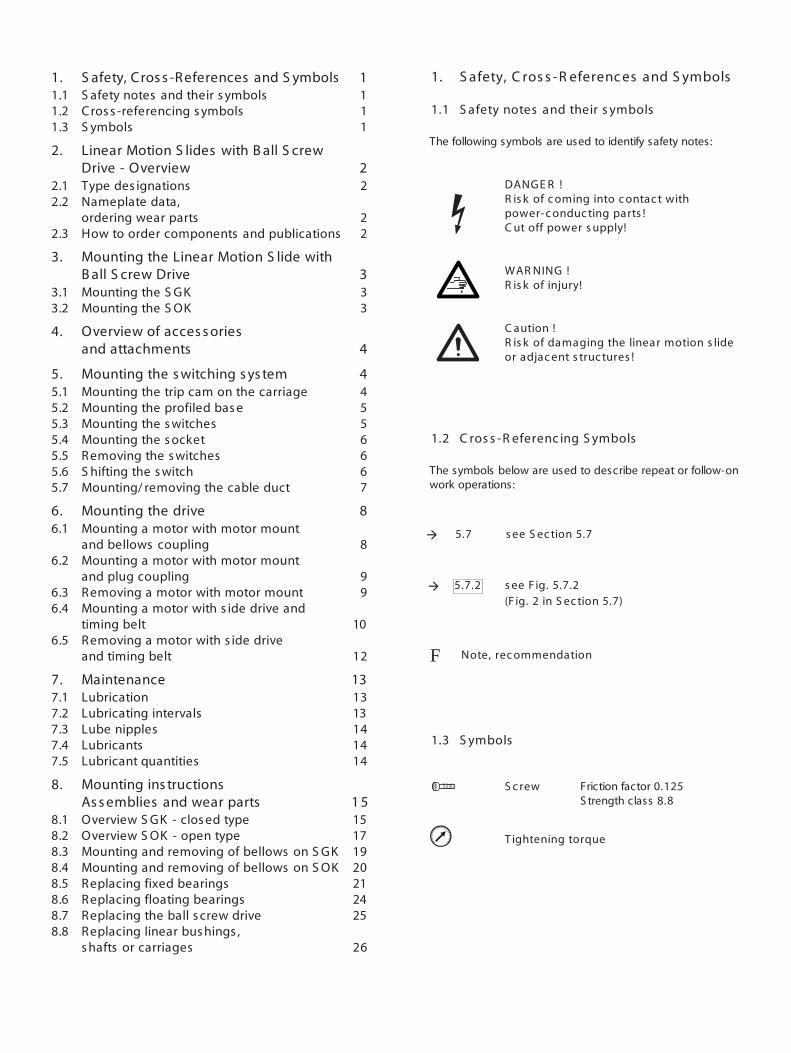
The following symbols are used to identify safety notes:
DANG E R !R is k of c oming into c ontac t withpower-c onduc ting parts !C ut off power s upply!
WAR NING !R is k of injury!
C aution !R is k of damaging the linear motion s lideor adjac ent s truc tures !
1.2 C ros s -R eferenc ing S ymbols
The symbols below are used to describe repeat or follow-onwork operations:
5.7 s ee S ec tion 5.7
5.7.2 s ee F ig. 5.7.2(F ig. 2 in S ec tion 5.7)
Note, rec ommendation
1.3 S ymbols
S c rew Friction factor 0.125S trength class 8.8
u T ightening torque
à
F
1 111
22
22
333
4
44556667
8
8
99
10
12
131313141414
1 515171920212425
26
à

2.1.2
2.1.1
12- 85 16-100 20-130 25-160 30-180 40-230 50-280
A 85 100 130 160 180 230 280
H 34 38 48 58 67 84 100
12- 85 16-100 20-130 25-160 30-180 40-230 50-280
A 85 100 130 160 180 230 280
H 40 48 57 66 77 95 115
2.2
2.3
D-97419 S chweinfurtTel. 09721/9370 - Fax 937350
0260,...52278/3
14.02.1997
TYPID - NrDatum
S TAR - matic
123
2. L inear Motion S lides withB all S c rew Drive -Overview
2.1 T ypes
Linear motion slides with ball screw driveare available as closed type (S GK) oropen type (S OK) and are supplied com-pletely preassembled. For technical dataand dimensions see the Linear MotionS lides catalog.
T hes e ins truc tions will helpappropriately trained s pec ialis ts tomount and maintain R exroth L inearMotion S lides .
2.2 Nameplate data,ordering wear parts
1 Part number of the linear motion slide2 S erial number3 Date of manufacture
• When ordering wear parts, please besure to indicate all of the data on thenameplate.
Bosch Rexroth
IndustrialHydraulics
Electric Drivesand Controls
Linear Motion andAssembly Technologies
ServiceAutomation
MobileHydraulicsPneumatics
The Drive and Control Company
Linear Motion Slides
SGK (Closed type)
SOK (Open type)
2.3 How to order componentsand publications
The catalog supplements these instructions and should be kept handyfor easy reference.
• Please order the latest publicationsfrom your local Rexroth sales partner.
F

3.1.1
3.1.2
3.2.1
3.2.2
L / 2
L
F
α
for friction factor 0.125 strength class 8.8
8.8 M4 M5 M6 M8 M10 M12 M14 M16 u (Nm) 2,7 5,5 9,5 23 46 80 123 194
3.2 Mounting the S OK
When ins talling L inear MotionS lides vertic ally or in an inc linedpos ition, prevent c arriage and s haftsfrom dropping down!
Use appropriate screws to suit themounting conditions. S ecure screwsagainst turning loose (e.g. by gluing,clamping coating, etc.).Use screws to DIN 6912 for bracing rails .Dismount bellows, if installed. 8.4For versions with bellows, placebracing rails on the shaft support railsand align them.
F irs t s haft s upport rail:Align and screw down the shaftsupport rail.Tightening torques 3.1.2
S ec ond s haft s upport rail:F irs t s tep: 3.2.1Push carriage to one end.Loosely insert one screw.S ec ond s tep: 3.2.2Push carriage to the other shaft end.Tighten the screw. 3.1.2To tighten the other screws, slide thecarriage close up to them.C heck that carriage moves easily and,if required, readjust second shaftsupport rail.Mount bellows, if any 8.4
3. Mounting the linearmotion s lide with balls c rew drive
3.1 Mounting the S G K
When ins talling L inear MotionS lides vertic ally or in an inc linedpos ition, prevent c arriage and s haftsfrom dropping down!
S crews to secure the shafts in the endblocks are supplied with the assembly.These screws can also be used tofasten the Linear Motion S lide.Depending on the mounting condi-tions, use longer screws if required.S ecure screws against turning loose(e.g., by gluing, clamping coating, etc.).Tightening torques 3.1.2
Obs erve permis s ible s haftinc lination in the L inear B us hing (s eeL inear Motion S lides c atalog).
à
•
•
•
••
•
•
•••••••
•
•
à
à
à
à
à
à•
5.1
4
10
9
8
7
65
43
2
1
¢
4. Overview of ac c es s oriesand attac hments
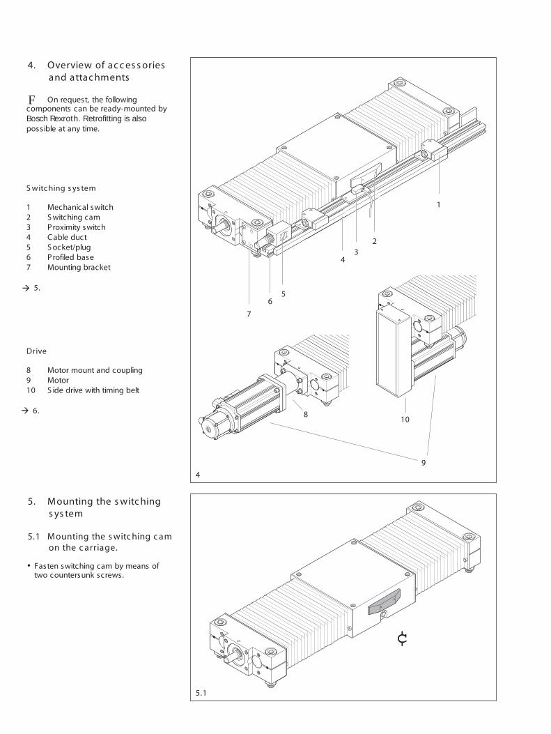
On request, the followingcomponents can be ready-mounted byBosch Rexroth. R etrofitting is alsopossible at any time.
S witc hing s ys tem
1 Mechanical switch2 S witching cam3 Proximity switch4 C able duct5 S ocket/plug6 Profiled base7 Mounting bracket
5.
Drive
8 Motor mount and coupling9 Motor10 S ide drive with timing belt
6.
5. Mounting the s witc hings ys tem
5.1 Mounting the s witc hing c amon the c arriage.
Fasten switching cam by means oftwo countersunk screws.
à
F
à
•

A C
S GK 12 - 85 5,5 - 4S GK 16 -100 5,5 - 6S GK 20 -130 6,5 4S GK 25 -160 6,5 7S GK 30 -180 7,5 14S GK 40 -230 9,0 2S GK 50 -280 9,0 2
S OK 12 - 85 5,5 - 2S OK 16 -100 5,5 - 2S OK 20 -130 6,5 6S OK 25 -160 6,5 9S OK 30 -180 7,5 17S OK 40 -230 9,0 7S OK 50 -280 9,0 9
5.3.2
5.3.1
5.2
D
0,4+0,2
A
A
2,5+0,2
C
A D
S GK 12 - 85 5,5 - 0,5S GK 16 -100 5,5 3,5S GK 20 -130 6,5 13,5S GK 25 -160 6,5 16,5S GK 30 -180 7,5 23,5S GK 40 -230 9,0 11,5S GK 50 -280 9,0 11,5
S OK 12 - 85 5,5 1,5S OK 16 -100 5,5 7,5S OK 20 -130 6,5 15,5S OK 25 -160 6,5 18,5S OK 30 -180 7,5 26,5S OK 40 -230 9,0 16,5S OK 50 -280 9,0 18,5
¢
¢
B
S GK / S OK 12 - 85 27S GK / S OK 16 -100 30
S GK / S OK 20 -130S GK / S OK 25 -160S GK / S OK 30 -180 40S GK / S OK 40 -230S GK / S OK 50 -280
4 5
32
1
[B
5.3 Mounting the switches
Mechanical switches
• Solder cable to the switch.• Screw switch to the switch mounting
plate.• Fix switch mounting plate on the pro-
filed base by means of square nutsand screws.
• Set switching intervals by adjusting theswitches 5.3.1
Negative dimensions C indicatethat the switch projects above thetop edge of the carriage.
Proximity switches
• Screw switch to the switch mountingplate
• Attach the switch mounting plate tothe profiled base by means of slotblocks and screws
• Set switching intervals by adjusting theswitches. 5.3.2
Negative dimensions D indicatethat the switch projects above thetop edge of the carriage.
5.2 Mounting the profiled base
• Cut profiled base (1) to the requiredlength and remove burrs.
• Align the fixed bearing side bracket (2)on the profiled base (1) and screw itdown.
• Slide the second bracket (3) looselyonto the profiled base (1).
• Screw first bracket (2) tightly to thefixed bearing end block (4).
• Screw second bracket (3) to thefloating bearing end block (5).
• Screw second bracket (3) down onthe profiled base (1).
Close adherence to the above sequenceallows easy adaptation to the slide'slength.
In exceptional serviceconditions (e.g., vibrations, longerstrokes) the profiled base must besupported in the vicinity of switches.
à
à

5.6
5.5
5.4
]
{
10
5
8
7
6
9
43
2
1
11
5.4 Mounting the socket
€ Insert and fasten the socket in thesame way as the switches. 5.3
Two seals are provided for the cableentry into the socket. One seal haspredrilled holes for the cables of twomechanical switches and one proximityswitch.
5.7
If more or less switches are required,drill the appropriate number of cableholes in the other seal.Thread all cables through the com-pression screw (1), the seal (2), thesocket housing (3), and the cork seal(4), taking into account the desiredconnecting position of the plug (5).Close the unused opening (6) in thesocket housing (3) using the O-ring (7)and screw plug (8).Solder cable into flanged connector(9). Draw a pin allocation diagram.Screw the flanged connector (9)onto the socket housing (3) withscrews (10).Press the seal (2) into the housing andsecure with compression screw (1).Insert the socket in the profiled baseand fix it in place using set screws.Mount cable duct. Solder cable into the plug (11).Check the switching circuit function.
•
•
•
•
•
•
•
•••
B efore putting the s ys tem inmotion, c hec k the E -s top s witc h!
� R un the first motion cycles atreduced speed in order to test the limitswitches and optimize the interaction ofmechanical and electronic components.
5.5 Removing the switches
C ut off power s upply beforeundertak ing any dis as s embly work !
€ Unsolder cables of mechanicalswitches.Unscrew switch mounting plate.Unscrew switches.
5.6 S hifting the s witc hes
C ut off power s upply!
For major relocations, the cable ductsmust be modified or replaced. 5.7
Proximity switch cables cannot beextended as the cables are potted intothe switches. If a proximity switch with alonger cable is needed, the best solutionis to buy a new switch.
à
F
à
à
•
•
••

5.7.3
5.7.2
5.7.1
300
99,5
2412
5
R 1,5
18 +0,5
5.7 Mounting/removing thec able duc t
� The cable duct accommodates amaximum of two cables for mechanicalswitches and three cables for proximityswitches.
Mounting the c able duc t
€ Measure length of cable duct.€ C ut cable duct to length and deburr.€ Measure, center-punch and drill holes
for the cable exits.€ If there is an insufficient number of
pre-drilled mounting holes, drilladditional holes in the base of thecable duct (2.5 deep, ø 3.1).
€ S nap cable duct into place in theslot on the profiled base and screwit down fast using the M3 x 8 mmscrews provided. For extra space inthe cable duct use M3 x 8 mm setscrews.
€ C ut cable grommets according tocable diameter and insert. Five cablegrommets 8624-024-02are provided.
€ Feed in cables and wire up.
Mounting a c able duc t lid withouts ide c over
€ Measure cable duct lid, cut to lengthand deburr.
€ S nap lid into place.
Mounting a c able duc t lid withs ide c over
Measure cable duct lid.Allow 18 mm for each side cover.C ut lid to length and deburr.R emove tabs in the bending area andat the end.B end lid and snap it into place.
R emoving the c able duc t
€ Widen lid at the end with a screwdriver
€Lift lid and tilt it out.
€Take out the cables.
€Unscrew and remove the mountingscrews.
€Pry the cable duct out of the profiledbase slot with a screw driver.
F
•••
•
•
•
•
€€€
€
••••
•
•
•
•
•••
•
€
€

6.1.3
6.1.2
8.8 M4 M5 M6 M8
u (Nm) 2,7 5,5 9,5 23
20 - 130 40 - 230S ize 25 - 160 50 - 280
30 - 180
8.8 M5 M6 M6
u (Nm) 8 14 13
6.1.5
6.1.4
6.1.1
€ Tighten the coupling mounting screwson the side facing the Linear MotionS lide. Tightening torques 6.1.3
€ To tighten the second screw, it maybe necessary to turn the ball screwdrive or shift the carriage so that theball screw drive turns. 6.1.4
€ Insert the motor into the centering holeof the motor mount and coupling andfix it in place with four screws.Tightening torques 6.1.2
€ Tighten the mounting screws of thecoupling on the side facing the motor.Tightening torques 6.1.3
€ To tighten the second screw, it maybe necessary to release the brake onthe motor, turn the ball screw drive sothat the ball screw drive turns.
B efore putting the s ys tem inmotion, c hec k the E -s top s witc h!
� R un the first motion cycles atreduced speed in order to test the limitswitches and optimize the interaction ofmechanical and electronic components.
6. Mounting the drive
6.1 Mounting a motor withmotor mount and bellowsc oupling
T he maximum torque ands peed of the motor mus t not exc eedthe permis s ible limits of the L inearMotion S lide!
€ S crew the motor mount to the linearmotion slide.Tightening torques 6.1.2
€ Ease the coupling into the motormount and onto the drive journalof the Linear Motion S lide until amounting screw on the couplingbecomes accessible through thehole in the motor mount.
à
à
à
à
à
•
•
•
•
•
••
••
F

6.3
6.2.2
6.2.1
B A
8.8 M4 M5 M6 M8
u (Nm) 2,7 5,5 9,5 23
Motor
6.3 R emoving a motor withmotor mount
When ins talling L inear MotionS lides vertic ally or in an inc linedpos ition, prevent c arriage and s haftsfrom dropping down!
C ut off power s upply !
For motors with bellows coupling only:unscrew the coupling mountingscrews on the motor side.
Unscrew and remove the motor fromthe motor mount.
S lide motor mount into the LinearMotion S lides centering hole andscrew it into place. Tightening torque
6. 2 . 2Align motor and one coupling half withthe other coupling half and firmly plugthem together.Align the motor with the motor mountcentering hole, s lide it into centeringhole and screw it in place.Tightening torques 6.2.2
B efore putting the s ys tem inmotion, c hec k the E -s top s witc h!
� R un the first motion cycles atreduced speed in order to test the limitswitches and optimize the interaction ofmechanical and electronic components.
6.2 Mounting a motor withmotor mount and plugc oupling
€ S lide the coupling halves onto thedrive journals of the Linear MotionS lide and the motor.
€ Adjust distances A and B accordingto the table below.
Size A B MA
± 0,1 ± 0,1(mm) (Nm)
12-85, 16-100 6,1 6,1 0,76
40-230, 50-280 15,8 21,7 10,5
Tighten screws on the coupling halveswith tightening torque MA .S lide the sprocket onto one couplinghalf.
F
à
à
•
•
•
•
•
•
•
•
•

€
€
€
Type 2Type 1
€
€
6.4.1
A
8.8 M2,5 M3 M4 M5
u (Nm) 1,2 2,1 4,9 9,7
6.4.2
8.8 M4 M5 M6
u (Nm) 2,9 6 10
6.4.3
1 2
Mounting c lamping as s embly type 1€ Lightly oil the clamping elements.
Do not us e oil c ontaining MoS 2
additives !
€ Push on the clamping assembly,tighten screws slightly, align the hub.
€ Tighten screws evenly, crosswise inseveral steps. Tightening torques
6. 4 . 2
Mounting c lamping as s embly type 2€ Lightly oil the clamping elements.
Do not us e oil c ontaining MoS 2
additives !
€ Push on the clamping assembly untilthe elements are completely containedwithin the belt pulley hole.
€ Tighten screws evenly, crosswise inseveral steps. Tightening torques
6. 4 . 2
6.4 Mounting a motor with s idedrive and timing belt
T he maximum torque ands peed of the motor mus t not exc eedthe permis s ible limits of the L inearMotion S lide!
Mounting the hous ing€ S crew the housing of the side drive
with timing belt to the Linear MotionS lide. Tightening torques for screwsM6: 9.5 Nm, for screws M8: 23 Nm.
Mounting the firs t belt pulley€ Push the belt pulley with flanged
wheels, mounted toothed belt andclamping assembly as a completeshaft-hub connection onto the journalof the Linear Motion S lide.
€ Adjust distance A to the housing.S izes 25-160, 30-180: A = 9.5 mmS izes 40-230, 50-280: A = 11 mm
Mount additional bearing, if pro-vided, to s upport the ball s c rewdrive journal
Mount first circlip as a stopper at theball screw end.Push bearing (1) manually onto the ballscrew end and secure with secondcirclip.C arefully push the bearing flange (2)onto the bearing and screw it in placeon the housing.Tightening torque = 1.3 Nm.
à
à
•
•
•
•
•
•
•
•
•
•
•
•

6.4.4
8.8 M6 M8
u (Nm) 9,5 23
1
2 F
6.4.5
1
2 F
C
8.8 M6 M8
u (Nm) 9,5 23
BS ize
(mm)
25-160, 30-180 940-230, 50-280 10
B
CS ize
(mm)
25-160, 30-180 1640-230, 50-280 19
Mounting the s ec ond belt pulley andmotor for i = 1.5 or i = 2
€ Push belt pulley and clampingassembly onto the motor journal.
€ Adjust distance C to the housing€ Mount clamping assembly. 6.4.2€ To allow easy threading of the second
belt pulley, the motor should be pre-assembled as close as possible tothe linear motion slide.
€ Do not tighten the motor mountingscrews.
€ S crew the appropriate screws inboth motor mounting fixtures (1)into the thread (2) provided for beltpretensioning.
� The pretensioning force F dependson the size of the Linear Motion S lide,the motor and the belt pulleys as well ason the torque. The pretensioning valuesare indicated on the inner side of thegear cover. If the side drive with timingbelt is not in horizontal position duringmounting, the dead weight of the motormust be taken into account!
€ Pull the motor away from the LinearMotion S lide with pretensioning forceF and screw in the mounting screws.Tightening torques 6.4.5
Mounting the s ec ond belt pulley andmotor for i = 1
€ To allow easy threading of the secondbelt pulley, the motor should be pre-assembled as close as possible tothe Linear Motion S lide.
€ Push belt pulley and clampingassembly onto the motor journal.Adjust distance B to the housingMount clamping assembly. 6.4.2
€ Loosen mounting screws.€ S crew the appropriate screws in both
motor mounting fixtures (1) into thethread (2) provided for belt preten-sioning.
� The pretensioning force F dependson the size of the Linear Motion S lide,the motor and the belt pulleys as well ason the torque. The pretensioning valuesare indicated on the inner side of thegear cover. If the side drive with timingbelt is not in horizontal position duringmounting, the dead weight of the motormust be taken into account!
€ Pull the motor away from the LinearMotion S lide with pretensioning forceF and screw in the mounting screws.Tightening torques 6.4.4
F
F
à
à
à
à
•
•
•
•
•
•
•
•
•
•
••
•
•
€€

6.5
6.4.6
6.5 R emoving a motor with s idedrive and timing belt
If the L inear Motion S lide isins talled vertic ally or in an inc linedpos ition, prevent the c arriage andthe s hafts from dropping down!
C ut off power s upply !
€ R emove the housing cover.
T he toothed belt is preten-s ioned. B e c areful when loos eningthe motor mounting s c rews .
Push the motor as close as possibleto the Linear Motion S lide.If the gear wheels are of identical size,loosen the lower clamping assembly.Extractor threads are provided in theclamping assemblies to facilitate theirremoval.
€ Unscrew and remove the motormounting screws and remove themotor.
� When dismantling the side drivewith timing belt proceed as appropriatefor the respective mounting variant.
C ompletion of the mountingproc edure
€ Attach all covers to the housing of theside drive with timing belt.
B efore putting the s ys tem inmotion, c hec k the E -s top s witc h!
� R un the first motion cycles atreduced speed in order to test the limitswitches and optimize the interaction ofmechanical and electronic components.
F
F
€€
•
•
•
•
•

Normal operating c onditions
10 °C ƒ 30 °CTemperature
Load Travel speed
< C /2 < 1 m/s
S ize S troke
12 … 85 > 65 mm16 … 100 > 70 mm20 … 130 > 95 mm25 … 160 > 135 mm30 … 180 > 170 mm40 … 230 > 190 mm50 … 280 > 250 mm
2500 min-1for ball screw drive maximum speed
7.2.1
R ec ommended lubric ationintervals
every 1 to 3 . 105 m of travel orevery 500 operating hours,whichever is reached first.
7.2.2
€
7. Maintenanc e
7.1 L ubric ation
Due to the initial lubrication carried outin-factory prior to shipment, the onlymaintenance work needed is in-servicelubrication of the Linear B ushings andthe Precision B all S crew Assembly tosuit the operating conditions.
The fixed and floating bearings of the ballscrew drive have been greased for lifeand will not require in-service lubricationunder normal circumstances.
7.2 L ubric ating intervals
Normal operating conditions, see Table.
Under special operating conditions (e.g.special configuration, presence of dust,solvents, etc.) the lubrication intervalsmust be adjusted to suit the specificapplication.
€ C lean shafts if necessary.•

S1
S ize
L ubric ant quantity per lube interval
Part number
N°
R elubrication quantity
(g)
S GK 12 - 85 0261-000-00 3,5 - -S OK 12 - 85 0266-000-00 - 3,9 2,6
S GK 16 - 100 0261-100-00 6,0 - -S OK 16 - 100 0266-100-00 - 5,6 3,7
S GK 20 - 130 0261-200-00 8,4 - -S OK 20 - 130 0266-200-00 - 9,8 6,5
S GK 25 - 160 0261-300-00 9,8 - -S OK 25 - 160 0266-300-00 - 16,7 11,2
S GK 30 - 180 0261-400-00 16,3 - -S OK 30 - 180 0266-400-00 - 25,1 16,7
S GK 40 - 230 0261-500-00 35,8 - -S OK 40 - 230 0266-500-00 - 26,5 17,7
S GK 50 - 280 0261-600-00 55,8 - -S OK 50 - 280 0266-600-00 - 69,8 46,5
7.5
S 1 S 2 S 3
7.3
SOK
SGK
S3
S2
S3
S2
S1
€
€
€
7.3 L ube nipples
€ For convenience, lube nipples areprovided on either side of the carriage.It is sufficient to lubricate from oneside only.
€ In the open version S OK, the lubricantmust be applied through one S 2 andone S 3 nipple each (see figure).
S 1 One-point lubricationfor closed type S GK
S 2 Lube nipplefor open type S OK for the linearbushing pair on the floating bear-ing side and the ball screw drive
S 3 Lube nipplefor the open type S OKfor the linear bushing pair on thefixed bearing side
S ize Lube nipple
12-85 ƒ 20-130 DIN 3405 AM 625-160 ƒ 50-280 DIN 3405 AM 8x1
7.4 L ubric ants
T he one-point lubric ation ofL inear Motion S lides S G K is de-s igned for greas e lubric ation only!
Do not us e greas es c ontainings olid partic les (e.g., graphite andMoS 2)!
We recommend the following:- lithium base grease KP2K (DIN 51825)- consistency class NLGI 2 (DIN 51818)
7.5 L ubric ant quantity
per lube interval, see table
€ When lubricating with a hand press,weigh out the quantity of grease perstroke.
•
•
•

8. Mounting ins truc tions - As s emblies and wear parts
8.1 Overview S G K - c los ed type
8.8 M3 M4 M5 M6 M8 M10 M12 M14 M16 u (Nm) 1,2 2,7 5,5 9,5 23 46 80 123 194
STARDeutsche Star Gmbh
D-97419 Schweinfurt
Tel. 09721/9370 - Fax 937275
SGK 30-18052278/3
07.07.1995
TYPID - NrDatum
STAR - matic
8.1
6
42
1
5
1
3

Item Ins truc tionsno. C omponent s ee
S ec tionAS = AssemblyWP = Wear part
1 AS B ellows 8.3WP B ellows
2 AS Fixed bearing 8.5Fixed bearing end block
WP Angular-contact ball bearing
3 AS Floating bearing 8.6Floating bearing end block
WP Deep-groove ball bearing
4 AS B all screw drive (B S D) 8.7
5 AS C arriage 8.8
6 S hafts 8.8
S eparate lists can be requested from Deutsche S tarfor wear parts.

1
8.2 Overview S OK - open type
S TARDeutsche S tar Gmbh
D-97419 S chweinfurt
Tel. 09721/9370 - Fax 937275
S GK 30-18052278/3
07.07.1995
TYPID - NrDatum
S TAR - matic
8.2
1
24
6
5
8.8 M3 M4 M5 M6 M8 M10 M12 M14 M16 u (Nm) 1,2 2,7 5,5 9,5 23 46 80 123 194
3

Item Ins truc tionsno. C omponent s ee
S ec tionAS = AssemblyWP = Wear part
1 AS B ellows 8.4WP B ellows
2 AS Fixed bearing 8.5Fixed bearing end block
WP Angular-contact ball bearing
3 AS Floating bearing 8.6Floating bearing end block
WP Deep-groove ball bearing
4 AS B all screw drive (B S D) 8.8
5 AS C arriage 8.8
6 S hafts 8.8
S eparate lists can be requested from B osch R exrothfor wear parts.

8.3.3
8.3.2
8.3.1
2
1
8.3 R emoving/mounting thebellows on the S G K
R emoving the bellows as s embly
C ut off power s upply beforeundertak ing any dis as s embly work !
If the L inear motion as s emblyis ins talled vertic ally or in an inc linedpos ition, prevent the c arriage andthe s hafts from dropping down!
€ R emove the motor. 6.3 or 6.5€ Unscrew the bellows mounting frame
from the carriage and the end blocks.€ R emove the floating bearing assembly.
8 . 6€ Pull off the bellows on the floating
bearing side.
Do not tear the bellows !
€ R emove the fixed bearing assembly. 8.5€ Pull off the bellows on the fixed
bearing side.
Do not tear the bellows !
R emove inner frame (1) and outerframe (2)
€ R emove the screws.€ Pull the inner frame (1) out of bellows.€ C ount the folds of the old bellows and
cut the new bellows to the appropriatelength.
Mounting the inner frame (1) andthe outer frame (2)
Insert the inner frame (1) into thebellows. The edges of the inner framemust be lodged behind the first com-plete fold in the bellows. The outeredges of the inner frame (1) must becompletely hidden.
€ C enter the inner frame (1).€ If the linear motion slide is installed
horizontally or in an inclined position,arrange the bellows so that the gluedjoint is on the underside.
€ Align the outer frame (2) with themount-ing holes on the carriage. Ifnecessary, turn the outer frame over.
€ S crew the outer frame (2) to the innerframe (1).
Mounting the bellows as s embly
€ S lide on the bellows assembly.Mount the floating bearing assembly.
6 . 6€ Mount the fixed bearing assembly. 6.5€ Align the bellows assembly with the
carriage, the floating bearing and thefixed bearing and screw it into place.Tightening torques 8.1
€ Mount the motor. 6.1, 6.2 or 6.4àà
àà
à
à
à•
•
•
•••
•
••
•
•
••
•
€€
€
••

8.4.4
8.4.2
8.4.1
8.4.3
“
“
“
1
2
Mounting the bellows as s embly
Fit one side of the bellows assembly allalong one shaft.One by one, angle the ribs of the otherbellows side down and snap them intoplace on the second shaft.Align the bellows assembly with thecarriage, the floating bearing and thefixed bearing and screw it into place.Tightening torques 8.2
8.4 R emoving/mounting thebellows on the S OK
R emoving the bellows as s embly
C ut off power s upply beforeundertak ing any dis as s embly work !
If the L inear motion as s emblyis ins talled vertic ally or in an inc linedpos ition, prevent the c arriage andthe s hafts from dropping down!
€ Unscrew the bellows mounting framefrom the carriage and the end block.
€ Grip the bellows at one corner and pullupward on one side. This will twist thefolds in bellows, allowing it to beeased off over the shafts.
R emoving the inner frame (1) andouter frame (2)
€ R emove the screws.€ Pull the inner frame (1) out of bellows.€ C ount the folds of the old bellows and
cut the new bellows to the appropriatelength.
Mounting the inner frame (1) andouter frame (2)
€ Position the inner frame (1) in the firstor last fold of the bellows so that it willclamp fast one bellows reinforcing ribon mounting.
€ Align the bellows and the inner frame(1) with the outer frame (2).
€ S crew the outer frame (2) to the innerframe (1).
à
•
•
€
•
•
•
••
•
••
•

STAR
Deutsche Star Gmbh
D-97419 Schweinfurt
Tel. 09721/9370 - Fax 937275
SGK 30-180
52278/3
07.07.1995
TYP
ID - Nr
Datum STAR - matic
8.5.3
8.5.2
8.5.1
STAR
Deutsche Star Gmbh
D-97419 Schweinfurt
Tel. 09721/9370 - Fax 937275
SGK 30-180
52278/3
07.07.1995
TYP
ID - Nr
Datum STAR - matic
1
3
2
1
3
R emoving a fixed bearing(angular c ontac t ball bearing)up to s ize 30-180
Mount plas tic jaws on the vis e.
€ C lamp the end block.
� The threaded ring is secured withLoctite 638 adhesive.
€ Heat up the threaded ring with a hotair blower until the adhesive melts,allowing the threaded ring to beremoved.
€ Unscrew and remove the threadedring with a face spanner.
€ P lace the end block on a recessedsupport, with the recess positionedbelow the fixed bearing.
€ C arefully push out the fixed bearing.
Do not reins tall any us edbearings !
8.5 R eplac ing fixed bearings
R emoving the end bloc k with thefixed bearing
C ut off power s upply beforeundertak ing any dis as s embly work !
If the L inear Motion S lide isins talled vertic ally or in an inc linedpos ition, prevent the c arriage andthe s hafts from dropping down!
If the fixed bearing is damaged,the c omplete as s embly mus t bereplac ed.
Move carriage to central position.€ R emove the motor 6.3 or 6.5€ Unscrew the bellows from the fixed
bearing end block 8.3 or 8.4€ Loosen the set screws (1) in the
slotted nut.
Us e a tool with plas tic jaws !
€ Hold the screw with this tool.€ Unscrew the slotted nut (2).€ Detach the socket head cap
screws (3).€ S upport the ball screw drive and the
shafts.€ C arefully pull the end block with the
fixed bearing off the ball screw driveand the shafts. Avoid tilting!
F
à
à
•
••
•
••
•
•
•
•
•
•
•

8.5.6
8.5.5
8.5.4
Loctite
STAR
Deutsche Star Gmbh
D-97419 Schweinfurt
Tel. 09721/9370 - Fax 937275
SGK 30-180
52278/3
07.07.1995
TYP
ID - Nr
Datum STAR - matic
3.
1.4.
2.
R emoving a fixed bearing (angularc ontac t ball bearing) s ize 40-230and over
Mount plas tic jaws on the vis e.
€ C lamp the end block€ Unscrew the socket head cap screws.€ Lever out the fixed bearing. Do not tilt
the bearing.
A bearing c an be internallyworn or damaged without this beingdetec table from the outs ide. Do notreus e defec tive bearings !
Mounting a fixed bearing(angular c ontac t ball bearing)up to s ize 30-180
Turn over the end block and place iton a flat support.C arefully push the new fixed bearinginto the end block up to the stop. Donot tilt it nor press on the bearing innerrace!Apply Loctite 638 adhesive to thethreaded ring and screw it tight.
S GK/ Threaded Tightening S OK ring torque
12- 85 M26x1,5 7 Nm16-100 M26x1,5 7 Nm20-130 M36x1,5 19 Nm25-160 M45x1,5 28 Nm30-180 M45x1,5 28 Nm
Mounting of a fixed bearing (angularc ontac t ball bearing) s ize 40-230and over
€ Turn over the end block and place iton a flat support.
€ C arefully push the new fixed bearinginto the end block up to the stop. Donot tilt it nor press on the bearing innerrace!
€ Use new self-locking cylinder headcap screws of strength class 8.8
€ Tighten screws crosswise.€ Tightening torque: 9.5 Nm.
•
•
•
•
•
•
•
•
•
•
•

8.5.8
8.5.7
1
2
2
STARDeutsche Star Gmbh
D-97419 Schweinfurt
Tel. 09721/9370 - Fax 937275
SGK 30-18052278/3
07.07.1995
TYPID - NrDatum
STAR - matic
€
Mounting the end bloc k with fixedbearing
€ Push the end block with the fixedbearing onto the screw of the ballscrew drive and the shafts.
Us e tool with plas tic jaws !
€ Hold the screw by means of this tool.€ Tighten the slotted nut to triple the
specified torque (1), unscrew it andretighten it to the specified torque.This preloads the fixed bearing.
€ Fix the slotted nut in place with twoset screws (2).
Thread and tightening torque MA
S GK/ S lotted nut S et S OK screw
MA MA
12- 85M8x0,75 0,6 Nm
16-100
20-130 M10x0,75 6 Nm M4 2 Nm
25-160M12x1 8 Nm
30-180
40-230M20x1 18 Nm M5 4 Nm
50-280
€ Align the end block with the shafts orthe shaft support rails .
S oc ket head c ap s c rews mus talready be ins erted in the end bloc kmounting holes bes ide the s hafts .
€ Tighten the socket head cap screws.Tightening torques 8.1 or 8.2
€ S crew the bellows to the end block.8.3 or 8.4
€ Mount the motor. 6.1, 6.2 or 6.4àà
à
••
•
•
•
•
•
8.6.3
8.6.2
8.6.1
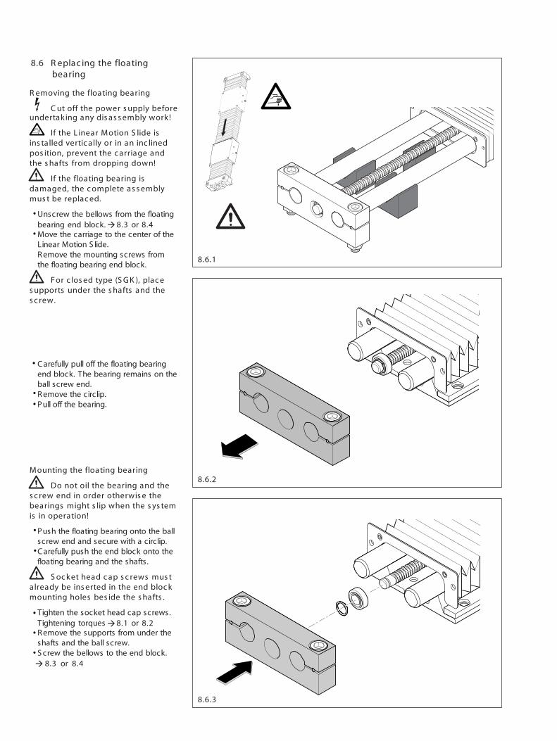
Mounting the floating bearing
Do not oil the bearing and thes c rew end in order otherwis e thebearings might s lip when the s ys temis in operation!
€ Push the floating bearing onto the ballscrew end and secure with a circlip.
€ C arefully push the end block onto thefloating bearing and the shafts.
S oc ket head c ap s c rews mus talready be ins erted in the end bloc kmounting holes bes ide the s hafts .
€ Tighten the socket head cap screws.Tightening torques 8.1 or 8.2
€ R emove the supports from under theshafts and the ball screw.
€ S crew the bellows to the end block.8.3 or 8.4
8.6 R eplac ing the floatingbearing
R emoving the floating bearing
C ut off the power s upply beforeundertak ing any dis as s embly work !
If the L inear Motion S lide isins talled vertic ally or in an inc linedpos ition, prevent the c arriage andthe s hafts from dropping down!
If the floating bearing isdamaged, the c omplete as s emblymus t be replac ed.
€ Unscrew the bellows from the floatingbearing end block. 8.3 or 8.4
€ Move the carriage to the center of theLinear Motion S lide.R emove the mounting screws fromthe floating bearing end block.
For c los ed type (S G K ), plac es upports under the s hafts and thes c rew.
€ C arefully pull off the floating bearingend block. The bearing remains on theball screw end.
€ R emove the circlip.€ Pull off the bearing.
à
à
à
•
•
•
•
•
•
•
•
•
•
!
!
8.7.2
8.7.3
8.7.1
€
€
€
€
€
€
SOK
SGK
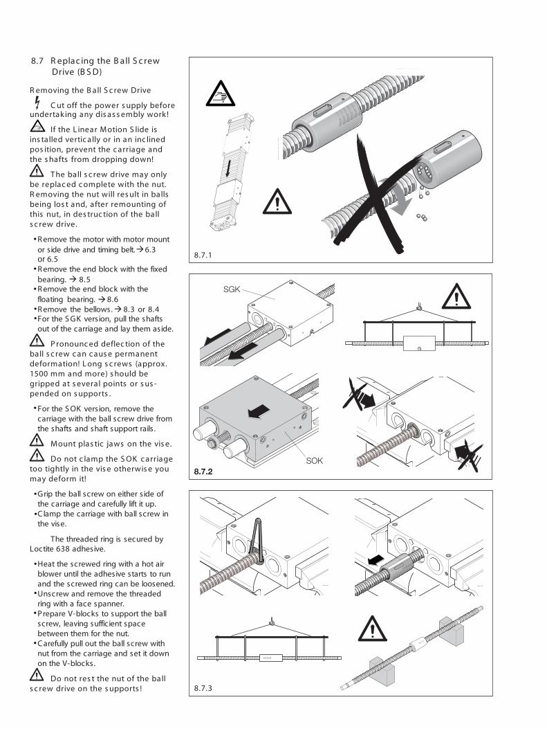
8.7 R eplac ing the B all S c rewDrive (B S D)
R emoving the B all S c rew Drive
C ut off the power s upply beforeundertak ing any dis as s embly work !
If the L inear Motion S lide isins talled vertic ally or in an inc linedpos ition, prevent the c arriage andthe s hafts from dropping down!
T he ball s c rew drive may onlybe replac ed c omplete with the nut.R emoving the nut will res ult in ballsbeing los t and, after remounting ofthis nut, in des truc tion of the balls c rew drive.
€ R emove the motor with motor mountor side drive and timing belt. 6.3 or 6.5
€ R emove the end block with the fixedbearing. 8.5
€ R emove the end block with thefloating bearing. 8.6
€ R emove the bellows. 8.3 or 8.4€ For the S GK version, pull the shafts
out of the carriage and lay them aside.
P ronounc ed deflec tion of theball s c rew c an c aus e permanentdeformation! L ong s c rews (approx.1500 mm and more) s hould begripped at s everal points or s us -pended on s upports .
€ For the S OK version, remove thecarriage with the ball screw drive fromthe shafts and shaft support rails .
Mount plas tic jaws on the vis e.
Do not c lamp the S OK c arriagetoo tightly in the vis e otherwis e youmay deform it!
€ Grip the ball screw on either side ofthe carriage and carefully lift it up.
€ C lamp the carriage with ball screw inthe vise.
� The threaded ring is secured byLoctite 638 adhesive.
€ Heat the screwed ring with a hot airblower until the adhesive starts to runand the screwed ring can be loosened.Unscrew and remove the threadedring with a face spanner.Prepare V-blocks to support the ballscrew, leaving sufficient spacebetween them for the nut.C arefully pull out the ball screw withnut from the carriage and set it downon the V-blocks.
Do not res t the nut of the balls c rew drive on the s upports !
àà
à
à
•
•
•
•
•
•
•
•
•
•
•
•

8.8
8.7.5
8.7.4
Loctite
31
2
Mounting the ball s c rew drive
P ronounc ed deflec tion of theball s c rew c an c aus e permanentdeformation! L ong s c rews (approx.1500 mm and more) s hould begripped at s everal points or s us -pended on s upports .
€ Insert the ball screw drive nut, lubehole (1) first, with the key (2) into thekeyway (3) of the carriage. Avoidtilting.
If the ball s c rew drive nut is notins erted with the lube hole (1) firs t, itwill be impos s ible to lubric ate theball s c rew drive in s ervic e.
€ C arefully insert the nut with the screwup to the stop. Avoid any impacts.
€ Apply Loctite 638 adhesive to thethreaded ring and screw it tight usinga face spanner.
Threaded ring tightening torques:
12- 85 M18x1 2 Nm
16-100 M26x1,5 7 Nm
20-130 M36x1,5 19 Nm
25-160M40x1,5 23 Nm
30-180
40-230M58x1,5 55 Nm
50-280
€ For the S GK version, insert the shaftsinto the carriage. Avoid tilting.
€ For the S OK version, grip the ballscrew on either side of the carriageand carefully lift it up. Push thecarriage with the ball screw drive ontothe shafts and the shaft support rails .Do not tilt.
€ S lip on the bellows.€ Mount the end block with the floating
bearing. 8.6€ Mount the end block with the fixed
bearing. 8.5€ Mount the bellows. 8.3 or 8.4€ Mount the motor with motor mount or
side drive with timing belt. 6.1, 6.2or 6.4
8.8 R eplac ing L inear B us hings ,S hafts or a C arriage
� T o guarantee the ac c urac yof the L inear Motion S lide afterreplac ement of linear bus hings ,s hafts or the c arriage, we re-c ommend that you s end in thec omplete L inear Motion S lide toBosch Rexroth Corporation.
F
à
àà
à
•
•
••
•
•
•
•
•
•
•

Bosch Rexroth CorporationCorporate Headquarters5150 Prairie Stone ParkwayHoffman Estates, IL 60192-3707Telephone (847) 645-3600Facsimile (847) 645-6201
Bosch Rexroth CorporationIndustrial Hydraulics2315 City Line RoadBethlehem, PA 18017-2131Telephone (610) 694-8300Facsimile (610) 694-8467
Bosch Rexroth CorporationElectric Drives and Controls5150 Prairie Stone ParkwayHoffman Estates, IL 60192-3707Telephone (847) 645-3600Facsimile (847) 645-6201
Bosch Rexroth CorporationPneumatics1953 Mercer RoadLexington, KY 40511-1021Telephone (859) 254-8031Facsimile (859) 281-3491
Bosch Rexroth CorporationMobile Hydraulics1700 Old Mansfield RoadWooster, OH 44691-0394Telephone (330) 263-3300Facsimile (330) 263-3333
RE 83 071Printed in the United States
Bosch Rexroth CorporationLinear Motion andAssembly Technologies14001 South Lakes DriveCharlotte, NC 28273Telephone (800) 438-5983Facsimile (704) 583-0523www.boschrexroth-us.com