instructions - det-tronics · designed for combustion turbine enclosure monitoring and similar air...
TRANSCRIPT

11.2 Rev: 9/15 95-8573
InstructionsDuctWatch Gas Detector/MonitorModel PIRDUCT

APPLICATION . . . . . . . . . . . . . . . . . . . . . . . . . . . . . . 1
FEATURES. . . . . . . . . . . . . . . . . . . . . . . . . . . . . . . . . 1
SPECIFICATIONS . . . . . . . . . . . . . . . . . . . . . . . . . . . 1
DESCRIPTION. . . . . . . . . . . . . . . . . . . . . . . . . . . . . . 5
Measurement Method . . . . . . . . . . . . . . . . . . . . . 5Detection Method. . . . . . . . . . . . . . . . . . . . . . . . . 5Current Loop Output . . . . . . . . . . . . . . . . . . . . . . 5Wiring Termination Box (Model PIRTB) . . . . . . . . 5Wiring FlexVu UD10-DCU . . . . . . . . . . . . . . . . . . 5Operating Modes . . . . . . . . . . . . . . . . . . . . . . . . . 5
INSTALLATION. . . . . . . . . . . . . . . . . . . . . . . . . . . . . . 6
Detector Location . . . . . . . . . . . . . . . . . . . . . . . . . 6Mounting Procedure . . . . . . . . . . . . . . . . . . . . . . . 7General Wiring Requirements . . . . . . . . . . . . . . . 8Detector Wiring Procedure . . . . . . . . . . . . . . . . . . 8
STARTUP PROCEDURE . . . . . . . . . . . . . . . . . . . . . . 9
CALIBRATION . . . . . . . . . . . . . . . . . . . . . . . . . . . . . 11
Calibration Equipment . . . . . . . . . . . . . . . . . . . . 11Calibration Procedures. . . . . . . . . . . . . . . . . . . . 11
MAINTENANCE . . . . . . . . . . . . . . . . . . . . . . . . . . . . 13
Disassembly and Cleaning Procedure . . . . . . . . 14
TROUBLESHOOTING . . . . . . . . . . . . . . . . . . . . . . . 17
REPLACEMENT PARTS . . . . . . . . . . . . . . . . . . . . . 17
DEVICE REPAIR AND RETURN . . . . . . . . . . . . . . . 17
ORDERING INFORMATION . . . . . . . . . . . . . . . . . . 18
PIRDUCT Model Matrix . . . . . . . . . . . . . . . . . . . 18Calibration Equipment . . . . . . . . . . . . . . . . . . . . 18Spare Parts . . . . . . . . . . . . . . . . . . . . . . . . . . . . 18Assistance . . . . . . . . . . . . . . . . . . . . . . . . . . . . . 18
APPENDIX A – FM APPROVAL . . . . . . . . . . . . . . . . 19
APPENDIX B – CSA APPROVAL. . . . . . . . . . . . . . . 20
APPENDIX C – ATEX APPROVAL . . . . . . . . . . . . . . 21
APPENDIX D – IECEX APPROVAL . . . . . . . . . . . . . 23
APPENDIX E – INMETRO APPROVAL . . . . . . . . . . 24
APPENDIX F – VNIIFTRI APPROVAL . . . . . . . . . . . 25
APPENDIX G – PIRDUCT WITH UD10-DCU. . . . . . 26
Table of Contents

1 95-857311.2
WARNINGBe sure to read and understand the entire instruction manual before installing or operating the gas detection system. This product is intended to provide early warning of the presence of a flammable or explosive gas mixture. Proper device installation, operation, and maintenance is required to ensure safe and effective operation. If this equipment is used in a manner not specified in this manual, safety protection may be impaired.
APPLICATIONThe DuctWatch Gas Detector/Monitor Model PIRDUCT is an infrared (IR) based flammable gas detection solution, designed for combustion turbine enclosure monitoring and similar air handling ductwork applications. The PIRDUCT is easy to install and commission, and does not require expensive extractive sampling system hardware. Providing a full scale measurement range of 0–15% LFL (0–7500 ppm) methane gas concentration, the PIRDUCT delivers a new level of flammable hydrocarbon gas protection for high airflow environments.
The PIRDUCT assembly is designed for mounting on any flat surface, and is provided pre-assembled with an aluminum mounting plate, seal gasket, and electrical termination junction box. A minimum internal duct width of 3 feet (1 meter) is required for proper installation.
PIRDUCT is CE compliant only when installed in large-scale fixed installations or large-scale stationary industrial tools. Examples of acceptable uses include large-sclale production and processing lines, machines for industrial production and processing of materials and goods, machines for testing of work pieces, paint booths, etc.
FEATURES• In-situ design improves gas response time and
simplifies installation• Continuous self-test automatically indicates a fault or
fouled optics condition• Routine calibration not required• Standard 4–20 mA signal output is proportional to
0–15% LFL (0-7500 ppm) methane• For use with PIRTB, DCU, and FlexVu® Models UD10
and UD10-DCU
SPECIFICATIONSINPUT VOLTAGE—+24 Vdc nominal (range +18 to +32 Vdc). Ripple must not exceed 0.5 volts peak-to-peak.
POWER CONSUMPTION (Watts)—Input Voltage: 18 Vdc 24 Vdc 32 Vdc
Nominal 3.5 4.6 6.2Maximum 4.0 5.5 7.0
DETECTION RANGE—0–15% LFL methane (0-7500 ppm).
GASES—Will respond to most hydrocarbon gases. Output is linearized for 0–15% LFL methane.
CURRENT OUTPUT (Non-Isolated)—Linear 4 to 20 mA current source.
• 4–20 mA output indicates 0–15% LFL detection range (linearized for methane)
• 23.2 mA indicates over-range condition
• 0–2.4 mA levels indicate calibration, fault and fouled optics conditions.
Refer to Table 1 for a detailed description of current outputs.
Maximum loop resistance: 580 ohms at +24 Vdc. See Figure 1 for further information.
INSTRUCTIONS
DuctWatch Gas Detector/Monitor
Model PIRDUCT
©2020 Detector Electronics Corporation Rev: 9/15
SUPPORTING DOCUMENTATION
Description Document Number
UD10 Manual 95-8661UD10-DCU Emulator Manual 95-8656EQP System Manual 95-8533

2 95-857311.2
NOTEThe following specifications for Accuracy and Temperature Stability are based on a 0–15% LFL methane calibration.
ACCURACY (Room Temperature)—±0.5% LFL from 0 to 7.5% LFL, ±0.75% LFL from 7.5% to 15% LFL.
RESPONSE TIME—T50 within eight seconds; T90 within 15 seconds.
TEMPERATURE STABILITY (Det-Tronics verified)—Zero: ±0.3% LFL from –40°C to +75°C (–40°F to +167°F).
Span: ±0.75% LFL at 50% of full scale from –25°C to +75°C (–13°F to +167°F),
±1.5% LFL at 50% of full scale from –40°C to –25°C– (40°F to –13°F).
WIRING—The PIRDUCT has five 22 AWG wires, 20 inches long for wiring into a termination box or the Infiniti transmitter. Red = + 24 Vdc Black = – (common) White = 4 to 20 milliampere signal output Yellow = Calibration input Green = Chassis ground
Power Wiring: 18 AWG minimum is recommended for power wiring. Larger diameter wire may be required to maintain a minimum of 18 Vdc (including ripple) at the sensor for all operating conditions (see Figure 2). For maximum EMI/RFI protection, shielded cable is recommended.
18 20 22 24
POWER SUPPLY VOLTAGE (VDC)
26 28 30 32
MA
XIM
UM
LO
OP
RE
SIS
TA
NC
E (
OH
MS
)
400
500
600
700
800
900
LOOP RESISTANCE (OHMS)
Figure 1—4 to 20 mA Current Loop Resistance
A2487
18 20 22 24
POWER SUPPLY VOLTAGE (VDC)
26 28 30 32
MA
XIM
UM
DIS
TA
NC
E F
RO
M P
OW
ER
SU
PP
LY
TO
PIR
DU
CT
IN F
EE
T
16 AWG14 AWG12 AWG 18 AWG
500
1000
1500
2000
2500
0
Figure 2—PIRDUCT Wiring Requirements
Table 1—Current Loop Output Levelsand Corresponding Status Indications
Current Level Status
23.2 mA Over-range (18% LFL)20.0 mA Full scale (15% LFL)4.0 mA Zero gas level (0% LFL)2.2 mA Zero calibration in progress2.0 mA Span calibration in progress1.8 mA Calibration complete - remove gas1.6 mA Calibration fault1.0 mA Fouled optics0.8 mA 24 Vdc line low (less than 17.5 Vdc)
0.6 mA Calibrate input active at power-up (probable wiring fault)
0.4 mA Active channel fault0.2 mA Reference channel fault
0.0 mA CPU system fault, warmup
3 95-857311.2
OPERATING TEMPERATURE RANGE—–40°C to +75°C (–40°F to +167°F).
STORAGE TEMPERATURE RANGE—–55°C to +85°C (–67°F to +185°F).
HUMIDITY (Non-Condensing)—0 to 99% relative humidity (Det-Tronics verified).5 to 95% relative humidity (FM/CSA verified).
RFI/EMI PROTECTION—EN61000-6-4. Class B, EN50270.Operates properly with 5 watt walkie talkie keyed at 1 meter.
INGRESS PROTECTION—IP66 (DEMKO certified per EN60529).
ENCLOSURE MATERIALS—Weather Protection Baffles: Aluminum.Electronics Assembly: Aluminum.
Aluminum (clear anodized) content: 0.8% to 1.2% Mg, 0.15% to 0.40% CU.
CERTIFICATION—
For complete approval details for the DuctWatch Gas Detector/Monitor Model PIRDUCT and the PointWatch Termination Box Model PIRTB, refer to the appropriate Appendix:
Appendix A - FMAppendix B - CSAAppendix C - ATEXAppendix D - IECExAppendix E - INMETROAppendix F - VNIIFTRI
WARNINGAlways ensure that the detector/termination box hazardous (classified) location ratings are applicable for the intended use.
ELECTRICAL TERMINATION ENCLOSURES—PIRDUCT is available pre-assembled with Det-Tronics PIRTB termination box or DCU* junction box for optimum ease of installation, commissioning, and calibration. The use of PIRDUCT with electrical termination enclosures other than Det-Tronics PIRTB or DCU may not be compatible depending upon the enclosure specifications.
*The EQ22xxDCU does not conform to EN50271-2010 for combustible gas or oxygen depletion. Use the UD10-DCU to satisfy this requirement.
SHIPPING WEIGHT (Approximate)—14.8 pounds (6.7 kilograms) - with Termination Box10.6 pounds (4.8 kilograms) - without Termination Box
DIMENSIONS—See Figure 3 for dimensions of the PIRDUCT and Figure 4 for dimensions of the Termination Box. See Figure 5 for dimensions of the mounting plate.
TERMINALS—Termination box terminals UL/CSA rated for 14 to 22 AWG wire; terminals DIN/VDE rated for 2.5 mm2 wire.
®

4 95-857311.2
Figure 4—Termination Box Dimensions in Inches (cm)
3.46(8.8)
4.7(11.9)
2.7(6.9)
5.2(13.2)
5.86(14.9)
6.57(16.7)
1.28(3.3)
A2307
2.5(6.4)
24.2(61.5)
PIRDUCT MOUNTING PLATE
6.5(16.5)
3.0(7.6)
D2227
Figure 3—Dimensions of PIRDUCT in Inches (cm)
2.0(5.1)
2.0(5.1)
9.0(22.9)
6.75(17.1)
0.5(1.3)
5.0(12.7)
2.75(7.0)
0.43 (1.1)
x 12E2279
DUCT CUTOUTAREA
GASKET SEALING AREA
MOUNT DETECTOR WITH AIRFLOW
IN THIS DIRECTION
PERIMETER OF MOUNTING PLATE AIRFLOW
Figure 5—Dimensions of PIRDUCT Mounting Plate in Inches (cm)

5 95-857311.2
DESCRIPTION
MEASUREMENT METHOD
PIRDUCT operates on the infrared absorption principle. A beam of modulated light is projected from an internal infrared source to a reflector, which sends it back to a pair of infrared sensors. One of the sensors is designated reference and the other active, with different optical filters in front of the two sensors to make them selective to different infrared wavelengths. The reference wavelength is unaffected by combustible gases, while the active wavelength is absorbed by combustible gases. The ratio of the active to the reference wavelength is computed within the PIRDUCT to determine the concentration of gas present. This value is then converted into a 4–20 milliampere current output for connection to external display and control systems.
DETECTION METHOD
PIRDUCT is an in-situ gas detector/monitor intended for applications with continuous air movement within gas turbine acoustic enclosures, air handling ductwork or similar enclosed spaces. The PIRDUCT is position sensitive and must be installed in the proper orientation for acceptable performance. As air flows through the enclosure or ductwork, it will intersect the PIRDUCT optics, and dangerous methane vapors present within the airflow will be detected and measured by PIRDUCT.
CURRENT LOOP OUTPUT
During normal operation, the PIRDUCT has a current output from 4 to 20 milliamperes that is proportional to gas concentrations from 0 to 15% LFL. A current output other than 4 to 20 milliamperes indicates a fault, over-range condition, or calibrate mode. Refer to Table 1 in the “Specifications” section for details.
WIRING TERMINATION BOX (MODEL PIRTB)
The PIRDUCT is furnished with a Wiring Termination Box that uses a tall cover with a viewing window. This termination box ensures optimum ease of installation and calibration. It includes a magnetic reed calibration switch and calibration LED (visible through a viewing window on the cover) to allow one person, non-intrusive calibration of the detector. The use of PIRDUCT with electrical termination enclosures other than Det-Tronics PIRTB or DCU may not be compatible depending upon the enclosure specifications.
WIRING FLEXVU UD10-DCU
The PIRDUCT can be wired to a UD10-DCU, making it compatible with LON based systems. Non-intrusive calibration and interrogation of the PIRDUCT can be performed from the UD10-DCU’s digital display. For more information on using the PIRDUCT with the UD10-DCU, see Appendix G.
OPERATING MODES
Warmup
When power is applied to the detector, it enters a Warmup mode (for approximately one minute) in which it performs diagnostic checks and allows the sensors to stabilize before beginning normal operation. The current output during this period is 0 milliamperes. At the end of the warmup period with no faults present, the detector automatically enters the Normal operating mode. If a fault is present after the warmup, the current output will be less than 4.0 mA. Refer to Table 1 in the Specifications section for fault diagnostic information.
Normal
In the normal operating mode, the 4–20 milliampere signal level corresponds to the detected gas concentration. The PIRDUCT continuously checks for system faults or initiation of calibration, and automatically changes to the appropriate mode.
Fault
Faults detected during warmup, normal operation, or calibration are indicated by the current loop output as shown in Table 1.
Calibration
All PIRDUCT models are factory calibrated using 7.5% LFL methane. Routine field calibration is normally not required, but can be performed. Calibration is required if the detector optics are ever disassembled. A calibration gas inlet nozzle is provided to enable introduction of calibration gas.
NOTETo successfully complete a ful l PIRDUCT calibration, a method of routing the methane calibration gas to the calibration gas inlet nozzle on the instrument is required.
NOTEA full PIRDUCT calibration will require temporary shutdown/removal of air movement to enable the calibration gas to remain within the measurement chamber for a sufficient time to ensure proper calibration.

6 95-857311.2
When installed with the Model PIRTB wiring termination box, field calibration of the PIRDUCT is easily performed using a non-intrusive, one-person calibration procedure. Calibration is initiated by actuating an internal magnetic reed switch. A calibration LED, easily visible through the viewing window on the cover of the termination box, signals the operator through the calibration process.
The factory default setting for the output current during calibration is an inhibited state. See Table 1 for specific information.
INSTALLATION
WARNINGAll entries must contain appropriately rated plugs or fittings. It is required that each plug or fitting be wrench-tightened to an appropriate installation torque and meets the minimum thread engagement requirements per the applicable local standards, codes, and practices in order to retain the defined ratings. PTFE sealant or equivalent should be used on NPT threads.
IMPORTANTHydrocarbon-based grease will emit hydrocarbon vapors which will be measured by PIRDUCT and will result in inaccurate gas level readings. Use only low vapor pressure silicone grease when lubricating threads on the PIRDUCT Detector/Monitor and associated termination box. Do not get this grease on the optics. A suitable grease is listed in the “Spare Parts” section at the end of this manual.
IMPORTANTIn applications where both PIRDUCT and catalytic type sensors are used, ensure that the silicone grease used to lubricate the PIRDUCT threads does not come into contact with the catalytic sensors or poisoning of the catalytic sensors will result. It is strongly recommended that maintenance personnel wash their hands between handling the two types of sensors.
DETECTOR LOCATION
Selecting the proper mounting location is crucial for proper gas detection. Following are some basic installation recommendations:
1. PIRDUCT should be installed downstream from bends, duct openings, or deflection plates. These locations provide fairly uniform, non-turbulent airflow, and are homogenous with respect to air/gas mixing. See Figure 6.
2. If airflow filters exist, it may be preferable to locate detectors on the upstream side of the filter. If a filter becomes blocked, insufficient air flow may cause improper operation of the detector. However, if the unfiltered airflow is unsuitable for direct exposure to the detector (due to the effects of contaminants, corrosive materials, moisture, heat, etc.) then an installation location downstream of the filter may be preferable.
3. Locate detectors so that dampers do not restrict air flow at the detector location.
4. Locate detectors where they can be conveniently observed and readily serviced.
RETURN AIRDAMPER
RETURNAIR
SUPPLYAIR
EXHAUST
FRESH AIR
INTAKE
DO NOT LOCATEDETECTOR HERE
PREFERREDLOCATION
PREFERREDLOCATION
SIDE VIEW
PREFERREDLOCATION
EXHAUSTDAMPER
MAY BE PREFERREDUNDER SOME CONDITIONS,
SEE TEXT FOR DETAILS
FILTERBANK
BEND OR OTHER OBSTRUCTION
RETURN AIRINLET
PREFERREDLOCATION
C2229
TOP VIEW
Figure 6—Detector Placement

7 95-857311.2
5. If in-situ calibration is required, determine required peripheral equipment (tubing, fittings, etc.) and ensure that installation requirements can be accommodated.
NOTEThe PIRDUCT Detector/Monitor is a position sensitive instrument. It must be installed in the proper orientation to achieve proper vapor detection. See Figure 7. Ensure that the installation location selected wil l accommodate the instrument in the proper mounting orientation.
NOTERefer to Appendix A for FM mounting requirements.
MOUNTING PROCEDURE
CAUTIONThe PIRDUCT mounting orientation is position sensitive. In all cases, the PIRDUCT must be installed with the air inlet holes facing into the airflow. The proper orientation is indicated on the PIRDUCT mounting plate.
NOTEThe PIRDUCT mounting plate is intended for installation to flat surfaces only. Although the horizontal mounting plane orientation is recommended, the PIRDUCT is compatible with horizontal or vertical mounting, provided the air inlet holes are installed facing upstream, e.g., directly into the airflow.
NOTEThe PIRDUCT mounting plate includes a seal gasket to ensure that no leakage of duct air occurs. In the event that duct wall insulation is present, it may be necessary to remove insulation to properly mount the PIRDUCT mounting plate.
1. When the proper mounting location has been identified, mark and drill the PIRDUCT assembly mounting holes in the proper pattern. Refer to Figure 5 for the mounting hole pattern dimensions.
2. Install the PIRDUCT into the duct. Secure the mounting plate to the duct wall using appropriate fasteners (self-tapping screw with outside diameter not exceeding 0.2 inch).
NOTEGas turbine enclosure walls are typically about 4–5 inches thick with substantial steel surfaces inside and out. Ensure that the PIRDUCT is securely and solidly installed in all cases.
3. Install optional calibration gas delivery hardware if desired.
Figure 7—Orientation of PIRDUCT Mounting Plate Relative to Direction of Airflow through Duct
Direction of Air Flow
Direction of Air Flow
CORRECT
INCORRECT
IMPORTANT: MOUNTING PLATE MUST BE ORIENTED AS SHOWN. ONCE THE MOUNTING PLATE IS SECURED TO THE DUCT WALL, THE TERMINATION BOX CAN BE ROTATED TO ANY CONVENIENT POSITION.
B2280

8 95-857311.2
GENERAL WIRING REQUIREMENTS
NOTEThe wiring procedures in this manual are intended to ensure proper functioning of the device under normal conditions. However, because of the many variations in wiring codes and regulations, total compliance to these ordinances cannot be guaranteed. Be certain that all wiring complies with applicable regulations relating to the installation of electrical equipment in a hazardous area. If in doubt, consult the authority having jurisdiction before wiring the system.
The use of shielded cable in conduit or shielded armored cable is recommended for optimum RFI/EMI protection. In applications where the wiring cable is installed in conduit, the conduit must not be used for wiring to other electrical equipment. To assure proper operation of the detector, the resistance of the connecting wire must be within the specified limits. The maximum distance between the detector and power source is determined by the power supply capability and wire size. Refer to Figure 2 in the “Specifications” section to determine the proper wire size and maximum wiring distance allowed.
It is important that moisture not be allowed to come in contact with the electrical connections of the system.
The use of proper piping techniques, breathers, glands, and seals are required to prevent water ingress and/or maintain the explosion-proof rating.
DETECTOR WIRING PROCEDURE
IMPORTANTDo not apply power until the wiring procedure is complete and has been verified.
Four or five conductor cable with an overall foil shield is recommended for wiring the PIRDUCT. The shield should be open at the detector termination box and connected directly to earth ground or to DC common via non-polarized capacitor at the signal receiver or controller. Ensure that the shield wire is clipped short and insulated with electrical tape to prevent accidental grounding at the open end.
IMPORTANTThe maximum distance between the detector termination box and the transmitter/control device is limited by the resistance of the connecting wiring, which is a function of the gauge of the wire being used. It is important to maintain a minimum of +18 Vdc (including ripple) at the PIRDUCT When determining the appropriate wire size and maximum separation distance for the installation, refer to Figure 2 in the “Specifications” section of this manual. Be sure to take into account the total distance from the power supply to the PIRDUCT to ensure that the power requirements are met.
1. The termination box should be electrically connected to earth ground.
2. Wire the PIRDUCT. Figures 8 through 11 show various system configurations. Refer to the appropriate figure as a guide to system connection.
Figure 8 shows typical wiring for stand alone operation.
Figure 9 shows typical wiring for PIRDUCT with Det-Tronics supplied termination box.
Figure 10 shows the termination box terminals and calibration switch.
Figure 11 shows a PIRDUCT wired to a DCU in an Eagle Quantum Premier® (EQP) system.
Figure 12 shows a PIRDUCT wired directly to a UD10.
Figure 13 shows a PIRDUCT wired to a UD10 (through the PIRTB).
The PIRDUCT wiring color code is:
Red lead = +24 Vdc Black lead = – (common) White lead = 4 to 20 mA signal output Yellow lead* = Calibration input Green lead = Chassis ground
* If the calibration wire (yellow lead) is not being used, do not connect this wire to ground. Trim excess length and insulate wire so no shorting can occur.
3. Check the detector wiring to ensure proper connections, then pour the conduit seals and allow them to dry (if conduit is being used).
4. Place the cover on the termination box.

9 95-857311.2
STARTUP PROCEDURE
1. Inhibit the output loads that are actuated by the system to prevent activation of these devices.
2. Check that the detector has been wired properly.
3. Apply power to the system and allow the detector to operate for a minimum of two hours. Check for 4 mA output and re-zero as required.
4. Place the system in normal operation by reactivating the output loads.
5. Perform a functional (response) test.
Figure 10—PIRTB Termination Box Terminals and Calibration Switch
CALIBRATE SWITCH
B2056
HOLD CALIBRATION MAGNETAT OUTSIDE BASE OF JUNCTION BOX AT THIS LOCATIONTO ACTIVATE CALIBRATION SWITCH
REMOTE LED
1
2
3
4
5
6
7
8
9
10
YELLOW
WHITE
BLACK
RED
GREEN
DCU PIRDUCT
14
13
12
11
–
–
+
+
24 VDC
CALIBRATE
4 TO 20 MA IN
–
+
A
B
A
B
SENSOR POWER
COM 2
COM SHIELD
COM 1
A2232
Figure 11—PIRDUCT Wired to DCU in anEagle Quantum Premier System
+24 VDC POWER OUT
4 TO 20 MILLIAMPERES IN
PIRDUCTDETECTOR/MONITOR
DET-TRONICS TERMINATION BOX
–+
C2231
GREENYELLOWWHITEBLACKRED
SPARE
CAL
4 – 20
RET
+24
CHASSIS
CAL
4 – 20
RET
+24
Figure 9—Typical Wiring, PIRDUCT with PIRTB Termination Box
Figure 8—Typical PIRDUCT Wiring, Stand Alone Configuration
–
REDBLACKWHITE
YELLOWGREEN
4 TO 20 MILLIAMPERESPIRDUCT DETECTOR/MONITOR
+
B2230
NOTE: CALIBRATION PUSHBUTT0N, CURRENT METER AND POWER SUPPLY ARE NOT SUPPLIED.
+24 VDCPOWER SUPPLY–
+
CALIBRATE

10 95-857311.2
UD10 DISPLAY UNIT
PIRDUCT
BLACK
RED
YELLOW
WHITE
GREEN
SEE NOTE 1
NOTE 1 CONNECT THE GREEN SENSOR LEAD TO THE CHASSIS GROUND LUG ON THE INSIDE BOTTOM OF THE DISPLAY ENCLOSURE.
NOTE 2 UD10 HOUSING MUST BE ELECTRICALLY CONNECTED TO EARTH GROUND.A2676
Sensor Connector
Power Supply Connector
Output LoopConnector
MODBUSConnector
Rel
ay C
on
nec
tor
P1
J2
J3
J4
P2
4-20 mA +
4-20 mA –
SHIELD
COM
RS485 A
RS485 B
HIGH ALARM COM
HIGH ALARM NC
HIGH ALARM NO
AUX ALARM COM
AUX ALARM NC
AUX ALARM NO
LOW ALARM COM
LOW ALARM NC
LOW ALARM NO
FAULT COM
FAULT NC
FAULT NO
24 V
DC
–
24 V
DC
+
SH
IEL
D
24 V
DC
–
24 V
DC
+
SH
IEL
D
SH
IEL
D
CA
LIB
RA
TE
24 V
DC
–
4-20
mA
24 V
DC
+
P1-3
P1-2
P1-1
J2-3
J2-2
J2-1
J4-1
J4-2
J4-3
J4-4
J4-5
J4-6
J4-7
J4-8
J4-9
J4-10
J4-11
J4-12
J3-1
J3-2
J3-3
J3-4
J3-5
P2-
6
P2-
5
P2-
4
P2-
3
P2-
2
P2-
1
UD10 DISPLAY UNITSEE NOTE 1
NOTE 1 CONNECT THE GREEN SENSOR LEAD TO THE CHASSIS GROUND LUG ON THE INSIDE BOTTOM OF THE PIRTB.
NOTE 2 HOUSINGS MUST BE ELECTRICALLY CONNECTED TO EARTH GROUND.A2677
Sensor Connector
Power Supply Connector
Output LoopConnector
MODBUSConnector
Rel
ay C
on
nec
tor
P1
J2
J3
J4
P2
4-20 mA +
4-20 mA –
SHIELD
COM
RS485 A
RS485 B
HIGH ALARM COM
HIGH ALARM NC
HIGH ALARM NO
AUX ALARM COM
AUX ALARM NC
AUX ALARM NO
LOW ALARM COM
LOW ALARM NC
LOW ALARM NO
FAULT COM
FAULT NC
FAULT NO
24 V
DC
–
24 V
DC
+
SH
IEL
D
24 V
DC
–
24 V
DC
+
SH
IEL
D
SH
IEL
D
CA
LIB
RA
TE
24 V
DC
–
4-20
mA
24 V
DC
+
P1-3
P1-2
P1-1
J2-3
J2-2
J2-1
J4-1
J4-2
J4-3
J4-4
J4-5
J4-6
J4-7
J4-8
J4-9
J4-10
J4-11
J4-12
J3-1
J3-2
J3-3
J3-4
J3-5
P2-
6
P2-
5
P2-
4
P2-
3
P2-
2
P2-
1
PIRTB JUNCTION BOX
PIRDUCT
YELLOWWHITEBLACKRED
SPARE
CAL
4 – 20
RET
+24 +24
RET
4 – 20
CAL
GREEN
CHASSIS
Figure 12—PIRDUCT Wired Directly to UD10
Figure 13— PIRDUCT Wired to UD10 through PIRTB Termination Box

11 95-857311.2
CALIBRATION
The PIRDUCT is factory calibrated for methane and, unlike catalytic detectors, does not require routine calibration to ensure proper operation. The PIRDUCT supports two different calibration options:
1. Zero only calibration. This procedure adjusts only the 4.0 mA (zero % gas) signal output of the PIRDUCT. It requires the presence of clean, hydrocarbon free air, and does not require application of 7.5% LFL methane calibration gas.
2. Zero and Span (full) calibration. This procedure adjusts both the 4.0 mA (zero % gas) signal output and the 50% full scale signal output. It requires the presence of clean, hydrocarbon free air, and the application of 7.5% LFL methane calibration gas.
The calibration initiation command is used to start both procedures. In the event the operator wishes to perform a Zero-only calibration, the magnetic calibration switch is re-actuated at the proper time to bypass the span calibration procedure.
IMPORTANTFor proper Zero calibration, the PIRDUCT must be calibrated in hydrocarbon free air. For proper Span calibration, the PIRDUCT must be calibrated in still air.
Functional (Response) Test
A functional test is performed to verify that the PIRDUCT responds accurately to the detected gas.
NOTEThe functional test may require temporary shutdown/removal of air movement to enable the calibration gas to remain within the detector’s measurement chamber to obtain an appropriate signal response.
To conduct a functional test, inhibit output loads as necessary, then apply 7.5% LFL calibration gas to the PIRDUCT. Check the current output for the appropriate response (12 milliamperes signal output). Calibration is recommended if the signal output during the test is not within ±0.2 mA of 12.0 mA signal level.
CALIBRATION EQUIPMENT
The following equipment is required for span calibration of the PIRDUCT (calibration kits from Det-Tronics contain the items below):
– 7.5% LFL methane calibration gas kit including regulator (minimum 2.5 liter/minute flow rate)
– Calibration gas delivery tubing.
CALIBRATION PROCEDURES
The procedures in this section explain calibration sequences for applications where PIRDUCT is used with the Det-Tronics supplied termination box (containing a magnetic reed switch and LED). For applications where the PIRDUCT is used with the EQP system, refer to the EQP system instruction manual for calibration procedures.
When PIRDUCT is used as a stand alone unit or with transmitters or controllers other than those supplied by Det-Tronics, the current loop output must be monitored in order to calibrate (for both inhibited and live current loop configurations).
When PIRDUCT is used with a Det-Tronics termination Box, the magnetic switch and LED in the termination box are used to initiate and annunciate the calibration sequence. The current loop output also indicates the calibration sequence (for both inhibited and live current loop configurations).
IMPORTANT CALIBRATION NOTES
• Ensure that the detector has been operating for at least two hours before calibrating.
• Do not open the explosion-proof enclosure when power is applied to the system unless the appropriate permits have been procured.
• The calibration sequence is initiated by momentarily connecting the calibration lead to the negative lead (common) of the power supply using the Cal Magnet or an external switch. If the Det-Tronics PIRTB box with magnetic Cal Switch is being used, this is accomplished by holding the Cal Magnet near the side of the PIRTB box for one second. The location of the Cal Switch is shown in Figure 10.
• The calibration sequence can be exited at any time during the span calibration by holding the Cal Magnet near the Cal Switch in the PIRTB box for one second.
• At all times other than when calibration is being performed, all calibration ports must be capped. This prevents dirt and water from entering the direct path into the optics. Failure to protect the optics can result in a fouled optics fault. If a permanent gas delivery system is used, the delivery tube must be plugged when not in use.

12 95-857311.2
Table 2—Calibration Sequence (Inhibited Current Output)
Calibration Procedure - Zero Calibration Only
IMPORTANTFor proper Zero calibration, the PIRDUCT must be calibrated in hydrocarbon free air.
See Table 2 for an overview of the calibration sequence.
1. Be sure that only clean air is present at the sensor. (The microprocessor begins taking zero readings immediately upon entering the Calibrate mode.) If the possibility of background gases exists (indicated by a small but constantly changing output), purge the sensor with clean air to ensure accurate calibration.
2. Initiate calibration by either momentarily activating the Calibrate pushbutton (shown in Figure 8) or by holding the Cal Magnet near the Cal Switch in the PIRTB box for one second.
– The LED will go on steady. – The current output will drop to 2.2 milliamperes.
3. Wait for the zero calibration point to stabilize (typically 1 minute).
After successful zero calibration:
– The LED will begin flashing, – The current will drop to 2.0 milliamperes.
Proceed to step 4.
If zero calibration fails:
– The LED will turn off, – The current output will drop to 1.6 milliamperes.
Reset the detector by cycling power to the detector or by holding the Cal Magnet near the Cal Switch in the PIRTB box for one second. Begin calibration again at step 1.
4. Apply the calibration magnet or activate the calibrate pushbutton for one second. The detector will return to normal operation using the span data from the last calibration.
Calibration Procedure - Zero and Span
IMPORTANTFor proper field calibration, the PIRDUCT must be calibrated in still air.
See Table 2 for an overview of the calibration sequence.
1. Be sure that only clean air is present at the sensor. (The microprocessor begins taking zero readings immediately upon entering the Calibrate mode.) If the possibility of background gases exists, purge the sensor with clean air to ensure accurate calibration.
2. Initiate calibration by either momentarily activating the Calibrate pushbutton (shown in Figure 8) or by holding the Cal Magnet near the Cal Switch in the PIRTB box for one second.
– The LED will go on steady. – The current output will drop to 2.2 milliamperes.
3. Wait for the zero calibration point to stabilize (typically 1 minute).
After successful zero calibration:
– The LED will begin flashing, – The current will drop to 2.0 milliamperes.
Proceed to step 4:
If zero calibration fails:
– The LED will turn off, – The current output will drop to 1.6 milliamperes.
Reset the detector by cycling power to the detector or by holding the Cal Magnet near the Cal Switch in the PIRTB box for one second. Begin calibration again at step 1.
Description Current LED Operator Action
Normal operation/no gas present 4.0 mA Off If the possibility of background gases exists, purge the sensor with clean air to ensure accurate calibration.
Initiate calibration 2.2 mA On steady Apply the calibration magnet or activate the calibrate pushbutton for one second.
Zero calibration complete 2.0 mA Flashing Apply 7.5% LFL methane calibration gas.
Span calibration complete * 1.8 mA OffShut off and remove calibration gas and cap the calibration nozzle (or replace it with the allen head plug).
Calibration fault indication 1.6 mA Off See Troubleshooting Section.
* Span calibration can be aborted (Zero Only Calibration) by applying the calibration magnet or activating the calibrate pushbutton for one second. The device will use the span data from the last calibration.

13 95-857311.2
4. Apply 7.5% LFL methane calibration gas to the detector. A 2.5 liter per minute flow rate is recommended.
– The LED will continue flashing. – The current will remain at 2.0 milliamperes as the gas concentration increases.
5. The detector will automatically accept the span calibration when the detected gas level is stable (typically 1 to 2 minutes).
After successful span calibration: – The LED will turn off, – The current will drop to 1.8 milliamperes.
Proceed to step 6.
If for any reason a successful calibration is not accomplished within 10 minutes, a calibration fault will occur:
– The LED will turn off, – The current output will drop to 1.6 milliamperes.
Turn off the gas, then reset the detector by cycling power to the detector or by holding the Cal Magnet near the Cal Switch. Begin calibration again at step 1.
6. After successful calibration, close the valve on the calibration gas canister and remove the flexible tube from the detector. The detector will return to normal operation after the gas level has dropped to near 0.
IMPORTANTThe calibration port must be capped to prevent dirt and water from entering the direct path into the optics. Failure to protect the optics can result in a fouled optics fault. If a permanent gas delivery system is used, the delivery tube must be plugged when not in use.
MAINTENANCE
The PIRDUCT requires less routine maintenance than other combustible gas detectors. This is accomplished through its design that allows no undisclosed internal failures, and an optics protection system that is extremely resistant to fouling by external contamination. The most significant benefit of this design is reduced calibration requirements. When installed and used per the manufacturer’s recommendations, the PIRDUCT does not require routine calibration, although an annual calibration inspection is recommended as a good practice. More frequent calibrations may be performed at the discretion of the user without adverse impact.
Other recommended maintenance practices include periodic visual inspections of the sensor and/or weather protection system. External contaminants and/or debris, if allowed to accumulate, can reduce sensitivity by physically blocking vapor access to the sensor. Common examples include plastic bags, litter, heavy oil and tar, paint, mud, and snow. This simple visual inspection of all gas sensors is a good idea, especially for outdoor installations.
In the unlikely event that the PIRDUCT indicates a fouled optics condition, it is possible to disassemble and clean the optics. However, it is recommended that a spare device be kept on hand to enable complete exchange of the electronics/optics module in the field, enabling the disassembly and cleaning operation to be performed in a clean lab environment.
IMPORTANT MAINTENANCE NOTES
• Hydrocarbon-based grease will emit hydrocarbon vapors, which will be measured by PIRDUCT and will cause inaccurate gas level readings. Use only silicone grease (not hydrocarbon-based grease) when lubricating threads on the PIRDUCT and associated termination box. A suitable grease is listed in the “Spare Parts” section at the end of this manual.
• In applications where both PIRDUCT and catalytic type sensors are used, ensure that the silicone grease used to lubricate the PIRDUCT threads does not come into contact with the catalytic sensors or poisoning of the catalytic sensors will result. It is strongly recommended that maintenance personnel wash their hands between handling the two types of sensors.

14 95-857311.2
DISASSEMBLY AND CLEANING PROCEDURE
The PIRDUCT should be inspected periodically to ensure that its performance is not impaired by fouled optics or by clogging of the filter or hydrophobic filter. Depending upon accessibility, it may be necessary to extract the detector from the duct in order to perform inspection. Inspection and/or periodic maintenance involves three different areas of the detector — the filter/baffle, the hydrophobic filter, and the detector optics.
IMPORTANTRemove power before disconnecting and removing the PIRDUCT for maintenance.
NOTEIt is not necessary to remove the electronics assembly from the detector base assembly in order to clean the detector optics.
Filter/Baffle. Perform a visual inspection of the filter/baffle, checking for a variety of environmental contaminants including nests of insects, spiders, etc. Disassemble the PIRDUCT and clean as necessary.
Hydrophobic Filter. While clogging of the hydrophobic filter is rare in most installations, the flow of gas through the filter could be inhibited by an accumulation of extremely fine particles of airborne contaminants. To inspect the hydrophobic filter, disassemble the PIRDUCT as described below. If the filter appears to be fouled or damaged, replace it.
IMPORTANTThe hydrophobic filter should be replaced whenever the mirror assembly and reflector tubes are cleaned or replaced, or when the filter appears fouled upon visual inspection.
Optics. Cleaning of the optical surfaces is required only if an optical fault is indicated (1.0 milliampere current output signal from the PIRDUCT). This procedure is most easily accomplished on a bench.
IMPORTANTIf the PIRDUCT optics system is disassembled, calibration is required after re-assembly.
Required materials: Clean, flat work surface, foam tipped swabs (no cotton), isopropyl alcohol, screwdriver or hex wrench.
CAUTIONThe PIRDUCT contains semiconductor devices that are susceptible to damage by electrostatic discharge. An electrostatic charge can build up on the skin and discharge when an object is touched. Therefore, use caution when handling the device, taking care not to touch electronic components or terminals. If the electronics assembly is removed, it should be placed in an anti-static bag or box while stored or transported. A static safeguarded work area is highly recommended (if available) for disassembly and cleaning of the PIRDUCT.
1. Slightly loosen the stabilization clamp to release the filter assembly and the shim from the electronics mounting cover. Do not remove the clamp completely from the electronics mounting cover. Keep the shim close by for re-assembly (see Figure 14).
2. Loosen the two captive screws on the end of the filter holder, then remove the filter assembly as shown in Figure 14.
3. Loosen the two captive screws on the mirror assembly (Figure 14) and remove the mirror assembly from the reflector tubes. See Figure 15.
4. Remove the hydrophobic filter and reflector tubes from the mounting tubes as shown in Figure 15. Do not remove the electronics mounting cover.
5. Thoroughly douse the interior of the mirror assembly as well as the foam tipped swab with isopropyl alcohol. Use the swab to gently cleanse the surfaces of the reflecting mirrors inside the mirror assembly. After cleaning with the swab, flush out the mirror assembly using a liberal amount of isopropyl alcohol. Tip the mirror assembly with mirror openings downward to remove accumulated isopropyl alcohol and particle contaminants. Repeat the alcohol flush to remove any remaining contaminants. Allow the mirror assembly to air dry in a dust-free location.
IMPORTANTDo not insert any sharp object into the mirror assembly. Scratching of the mirrors will void the PIRDUCT warranty. Do not use cotton tipped swabs or buds as they are likely to leave fiber residue.

15 95-857311.2
6. Clean the two reflector tubes and windows using the procedure described in Step 5. When the mirror assembly, windows, and reflector tubes are thoroughly dry, proceed with re-assembly.
7. Make sure that the retainers that hold the reflector tubes in place are evenly spaced on the tubes and not blocking any holes. Carefully reinstall the reflector tubes on the mounting tubes and seat the reflector tubes securely into the windows in the base.
8. Slide the hydrophobic filter over the reflector tubes. Be careful not to crumple or fold the hydrophobic filter.
9. Insert the ends of the two reflector tubes into the larger holes in the mirror assembly and ensure that they are fully seated. Note the match mark on the reflector tubes and the dimple on the mirror assembly. These should be aligned, as illustrated in Figure 16.
10. Tighten the two captive screws on the mirror assembly. See Figure 14. Tighten the screws evenly. Do not over-tighten (apply 1 N-m minimum torque).
11. Using one hand, wrap the shim around the electronics mounting cover and keep it in place. Use another hand to slide the filter assembly over the mirror assembly and the shim. Align the slots and guides as illustrated in Figure 17, then fasten the stabilization clamp.
12. Fasten the two captive screws on the filter holder.
13. Attach the gas supply tube.
14. Calibrate the detector with 7.5% LFL methane following the instructions in the “Calibration” section of this manual.
D2233
REFLECTOR TUBES PROTECTED BY HYDROPHOBIC FILTER
SHIM
CAPTIVE SCREWS (2)
FILTER ASSEMBLY
GAS SUPPLY TUBE
STABILIZATIONCLAMP
FILTER HOLDER
MIRROR ASSEMBLY
Figure 14—PIRDUCT with Filter Assembly Removed
DETECTOR BASEASSEMBLY
MOUNTING PLATE
ELECTRONICS MOUNTING COVER
WINDOWS (2)
MOUNTING TUBES (2)
HYDROPHOBIC FILTER
MIRROR ASSEMBLY
MIRRORS (2)
REFLECTOR TUBES (2) RETAINER (5)
D2234
Figure 15—PIRDUCT Disassembled for Cleaning

16 95-857311.2
ALIGN ALL 4 SLOTS ON THE FILTERASSEMBLY WITH THE 4 GUIDES ON THE DETECTOR BASE ASSEMBLY.
A2595
Figure 17—Filter Assembly Slots Line Up with Detector Base Assembly Guides
DIMPLEON MIRRORASSEMBLY
MATCH MARKON REFLECTORTUBE
A2594
Figure 16—Match Mark on Reflector Tube Lines Up with Dimple on Mirror Assembly

17 95-857311.2
TROUBLESHOOTING
Use Table 3 to isolate and correct malfunctions with the PIRDUCT Detector/Monitor.
REPLACEMENT PARTS
The DuctWatch Gas Detector/Monitor Model PIRDUCT is not designed to be repaired in the field. If a problem should develop, refer to the Troubleshooting section. If it is determined that the problem is caused by an electronic defect, the device must be returned to the factory for repair.
DEVICE REPAIR AND RETURN
Prior to returning devices, contact the nearest local Detector Electronics office so that a Return Material Identification (RMI) number can be assigned. A written statement describing the malfunction must accompany the returned device or component to assist and expedite finding the root cause of the failure.
Pack the unit properly. Always use sufficient packing material. Where applicable, use an antistatic bag as protection from electrostatic discharge.
NOTEDet-Tronics reserves the right to apply a service charge for repairing returned product damaged as a result of improper packaging.
Return all equipment transportation prepaid to the factory in Minneapolis.
NOTE It is highly recommended that a complete spare be kept on hand for field replacement to ensure continuous protection.
Current Level Status Corrective Action
2.4 to 3.9 mA Negative Gas Indication NOTE: This phenomenon is typically caused either by the presence of background gas during zero calibration, or by condensation on the device optics. If low level background hydrocarbon gas was present during calibration, the result will be a signal output level below 4 mA when the background gas clears. To correct this, the device must be re-zeroed with all background gas removed.
1.6 mA Calibration fault Use 7.5% LFL methane for calibration. If the fault is still present, perform disassembly and cleaning procedure, then recalibrate.
1.0 mA Fouled optics Perform disassembly and cleaning procedure, then recalibrate.
0.8 mA +24 Vdc line low (less than +17.5 Vdc) Ensure that input voltage is correct and that power connections are good. If fault does not clear, replace the electronics assembly.
0.6 mA Calibrate input active at power-up Ensure that calibration line is not shorted and that the calibration switch is open. If fault does not clear, replace the unit.
0.4 mA Active channel fault Replace the unit.
0.2 mA Reference channel fault Replace the unit.
0.0 mA CPU system fault, warmup Ensure that power is applied and that the warmup period is complete (1 minute). If fault does not clear, replace the unit.
Table 3—Troubleshooting Guide

18 95-857311.2
PIRDUCT MODEL MATRIX
MODEL DESCRIPTION
PIRDUCT Point Infrared DuctWatch Gas Detector/MonitorTYPE THREAD TYPE
A 3/4” NPTB M25
TYPE SIGNAL OUTPUT
2 4-20 mATYPE APPROVALS
B INMETRO (Brazil)W FM/CSA/ATEX/IECExR VNIIFTRI (Russia)
TYPE WIRING TERMINATION JUNCTION BOX
1 Factory-fit with PIRTBA5NW3V (std 4-20 mA), AL, 3/4”NPT cable entry2 Factory-fit with PIRTBA5LW3V (std 4-20 mA), AL, M25 cable entry3 Factory-fit with EQ2253DCU (EQP sys only), AL, 3/4”NPT cable entry4 Factory-fit with EQ2207DCU (EQP sys only), AL, M25 cable entry5 No factory-fit wiring j-box provided
NOTE: UD10-DCU is ordered separately. Reference the UD10-DCU Emulator manual for ordering information.
ORDERING INFORMATION
CALIBRATION EQUIPMENT
PIRDUCT calibration kits consist of a sturdy carrying case containing two 3.6 cubic foot (103 liter) cylinders of 7.5% LFL methane gas, a regulator and pressure indicator, three feet of tubing, and a nozzle for direct application to the detector.
Calibration Kit 006468-007
Calibration Kit (Russian) 006468-917
Spare Cylinder of 7.5% LFL Methane Gas 226166-012
Spare Cylinder of 7.5% LFLMethane Gas (Russian) 226166-917
SPARE PARTS
Description Part Number
Hydrophobic Filter Replacement Kit 006876-002
Clamp and Shim Kit for PIRDUCT 011908-001
Calibration Magnet 102740-002
Silicone Grease for PIRDUCT threads 006680-001 (6 cc syringe)
Lubriplate Grease, 1 oz. 005003-001

19 95-857311.2
APPENDIX A
FM APPROVAL
The following items, functions, and options describe the FM approval.
APPROVAL
PIRDUCT Detector/Monitor.
Explosion-proof for Class I, Division 1, Groups B, C, and D (T5) Hazardous (Classified) Locations per FM 3615.Nonincendive for Class I, Division 2, Groups A, B, C, and D (T3C) Hazardous (Classified) Locations per FM 3611.Performance verified for 0 to 15% LFL Methane-in-air atmospheres per FM 6320.
NOTEModel PIRDUCT must be used in conjunction with an FM Approved control device.
PointWatch Termination Box (Part Number 006414-XXX).
Explosion-proof for Class I, Division 1, Groups B, C, and D (T6) Hazardous (Classified) Locations per FM 3615.Nonincendive for Class I, Division 2, Groups A, B, C, and D (T6) Hazardous (Classified) Locations per FM 3611.
NOTEApproval of the PIRDUCT and termination box does not include or imply approval of the apparatus to which the PIRDUCT may be connected and which processes the electronic signal for eventual end use.
Special Conditions for Safe Use:When installed in a gas turbine exhaust duct, the duct width cannot exceed 8.2 feet (2.5 meters) and the cross sectional area cannot exceed 67.2 feet2 (6.25 meters2). The distance between PIRDUCT and the exhaust duct inlet must be at least four times the width of the exhaust duct. In addition, an FM Approved gas detector must be used for monitoring the fuel line of the gas turbine for potential leaks.
ATTACHMENTS/OPTIONS
Aluminum Explosion-proof Enclosure.3/4 inch NPT and M20 Conduit Entry Thread Types. (Metric straight thread is for use in non-North American applications.)Calibration Kit (006468-007) 7.5% LFL Calibration Gas (226166-012) Calibration Nozzle (102821-001) Regulator (162552-002) Tubing (101678-007)
CALIBRATION
The DuctWatch Gas Detector Model PIRDUCT can be calibrated as a stand-alone device.PointWatch Termination Box (006414-xxx) can be used to calibrate the PIRDUCT Detector.
NOTEIt is required that a function test be performed on the system in which the PIRDUCT is installed.

20 95-857311.2
APPENDIX B
CSA APPROVAL
DuctWatch Gas Detector/Monitor Model PIRDUCT
CLASS 4828 01 - SIGNAL APPLIANCES - Combustible Gas Detection Instruments - For Hazardous LocationsClass I, Div. 1, Groups B, C, and D (T5);Class I, Div. 2, Groups A, B, C, and D (T3C).
PointWatch Termination Box
CLASS 4828 01 - SIGNAL APPLIANCES - Combustible Gas Detection Instruments - For Hazardous LocationsClass I, Div. 1, Groups B, C, and D (T6). Class I, Div. 2, Groups A, B, C, and D (T6).

21 95-857311.2
APPENDIX C
ATEX APPROVAL
ATEX CERTIFICATION
DuctWatch Gas Detector/Monitor Model PIRDUCT
0539 FMAPPROVED
® II 2 GEx db IIB+H2 T6...T4EN 60079-29-1DEMKO 09 ATEX 147623XT6 (Tamb = –55°C to +50°C)T5 (Tamb = –55°C to +60°C)T4 (Tamb = –55°C to +75°C)IP66.
EN Standards: EN 50270: 2006 EN 60079-0: 2012 + A11:2013 EN 60079-1: 2007
EN 60529: 1991+A1: 2000 EN 60079-29-1: 2007
Read and understand instruction manual before operating.
Special Conditions for Safe Use:The DuctWatch Gas Monitor, Model PIRDUCT has threaded wire feed through incorporating flying leads. The feed through is to be screwed into the cable entry opening of a suitable certified (Ex ‘d’ or Ex ‘e’) enclosure in which the flying leads are to be terminated
In order to maintain the Ingress Protection rating IP66, the back end of the DuctWatch Gas Monitor Model PIRDUCT with the flying leads is to be screwed into a suitable certified flameproof enclosure with an Ingress Protection rating of at least IP66.
The DuctWatch Gas Monitor Model PIRDUCT has an ambient temperature rating for performance of –40°C to +75°C.
The DuctWatch Gas Monitor Model PIRDUCT is to be used only in conjunction with a suitable ATEX certified combustible gas detector control unit compliance with EN 60079-29-1 Series standards.
The captive front end screws are to be tightened with 1 Nm.
Performance Testing to EN60079-29-1The measuring function of the DuctWatch Gas Monitor Model PIRDUCT is, for methane, covered in this Type Examination Certificate in the following configuration:
1. PIRDUCT Gas Monitor with STB (tested as a gas detection system with methane applied).
CE MARK
The Model PIRDUCT DuctWatch Infrared Hydrocarbon Gas Detector was tested and found to be compliant with EN 50270 when wired in conduit or with shielded cable. All screen drains shall be terminated to the chassis.
PIRDUCT is CE compliant only when installed in large-scale fixed installations or large-scale stationary industrial tools. Examples of acceptable uses include large-sclale production and processing lines, machines for industrial production and processing of materials and goods, machines for testing of work pieces, paint booths, etc.

22 95-857311.2
PointWatch Termination Box Model PIRTB
0539 FMAPPROVED
® II 2 GEx db IIC T5-T6EN 60079-29-1DEMKO 02 ATEX 131326T6 (Tamb = –55°C to +60°C)T5 (Tamb = –55°C to +75°C)IP66.
EN Standards: EN 60079-0: 2012 + A11:2013 EN 60079-1: 2007 EN 60529: 1991+A1: 2000
EN 60079-29-1: 2007
All cable entry devices and blanking elements shall be certified in type of explosion protection flameproof enclosure ‘d’, suitable for the conditions of use and correctly installed. Unused apertures shall be closed with suitable certified blanking elements.
For ambient temperatures below –10°C and above +60°C, use field wiring suitable for both minimum and maximum ambient temperatures.
Performance testing to EN 60079-29-1The measuring function of the PointWatch Termination Box Model PIRTB, according to Annex II paragraph 1.5.5, 1.5.6 and 1.5.7 of the Directive 94/9/EC, is (for methane) covered in this EC-type Examination Certificate in the following configuration:
PointWatch Termination Box, model PIRTB, in combination with Det-Tronics gas detector models PIR9400, PIRDUCT or PIRECL (with methane applied to the gas detectors).

23 95-857311.2
APPENDIX D
IECEx APPROVAL
DuctWatch Gas Detector/Monitor Model PIRDUCT
IECEx ULD 10.0019XEx db IIB+H2 T6...T4T6 (Tamb = –55°C to +50°C)T5 (Tamb = –55°C to +60°C)T4 (Tamb = –55°C to +75°C)IP66.
IEC Standards: IEC 60079-0: 2011-06, Edition 6.0 IEC 60079-1: 2007 IEC 60529, 2.1.ed.+Corr.1:2003+2:2007
CONDITIONS OF CERTIFICATION:
The DuctWatch Gas Monitor Model PIRDUCT has a threaded wire feed through incorporating flying leads. This feed through is to be screwed into the cable entry opening of a suitable certified (Ex ‘d’ or Ex ‘e’) enclosure in which the flying leads are to be terminated.
In order to maintain the Ingress Protection rating IP66, the back end of the DuctWatch Gas Monitor Model PIRDUCT with the flying leads is to be screwed into a suitable certified flameproof enclosure with an Ingress Protection rating of at least IP66.
The captive front end screws are to be tightened with 1 Nm.
PointWatch Termination Box Model PIRTB
IECEx ULD 10.0002Ex db IIC T5-T6T6 (Tamb = –55°C to +60°C)T5 (Tamb = –55°C to +75°C)IP66.
IEC Standards: IEC 60079-0: 2011-06, Edition 6.0 IEC 60079-1: 2007-4, Edition 6.0 IEC 60529, 2.1.ed.+Corr.1:2003+2:2007
All cable entry devices and blanking elements shall be certified in type of explosion protection flameproof enclosure ‘d’, suitable for the conditions of use and correctly installed. Unused apertures shall be closed with suitable certified blanking elements.
For ambient temperatures below –10°C and above +60°C, use field wiring suitable for both minimum and maximum ambient temperatures.

24 95-857311.2
APPENDIX E
INMETRO APPROVAL
DuctWatch Gas Detector/Monitor Model PIRDUCT
UL-BR 15.0379XEx d IIB+H2 T4-T6 Gb IP66T6 (Tamb = –55°C to +50°C)T5 (Tamb = –55°C to +60°C)T4 (Tamb = –55°C to +75°C).
IEC Standards: IEC 60079-0: 2008+A1:2011 IEC 60079-1: 2009+A1:2011 IEC 60529, 2.1. Ed. +Corr. 1:2003 + 2:2007
NOTEThreaded adapters shall be Brazil certified with an ingress protection rating of IP66.
PointWatch Termination Box Model PIRTB
UL-BR 15.0313Ex d IIC T5-T6 Gb IP66T6 (Tamb = –55°C to +60°C)T5 (Tamb = –55°C to +75°C)
IEC Standards: IEC 60079-0: 2008+A1:2011 IEC 60079-1: 2009+A1:2011 IEC 60529, 2.1. Ed. +Corr. 1:2003 + 2:2007
NOTEAll cable entry devices and blanking elements shall be Brazil certified in the type of explosion protection, flameproof enclosure “d,” suitable for the conditions of use and correctly installed, with an ingress protection rating of IP66. A screw or cover lock is provided for a secondary means of fastening the cover.

25 95-857311.2
APPENDIX F
VNIIFTRI APPROVAL
RUSSIA
VNIIFTRICERTIFICATE OF CONFORMITY to TP TC 012/2011
DuctWatch Gas Detector/Monitor Model PIRDUCT
1ExdIIBT4-T6/H2 XT6 (Tamb = –55°C to +50°C)T5 (Tamb = –55°C to +60°C)T4 (Tamb = –55°C to +75°C)IP66.
PointWatch Termination Box Model PIRTB
1ExdIICT6/T5T6 (Tamb = –55°C to +60°C)T5 (Tamb = –55°C to +75°C)IP66.

26 95-857311.2
APPENDIX G
PIRDUCT with UD10-DCU
WIRING PROCEDURE
FLEXVU UD10-DCU SWITCHES
These switches are used for device configuration, checking status and event logs, and performing calibration. The switches are labeled as follows:
Sensor Connector
Power Supply Connector
LON
Co
nn
ecto
r
J4
J3
J7
24 V
DC
–
24 V
DC
+
SH
IEL
D
24 V
DC
–
24 V
DC
+
SH
IEL
D
SH
IEL
D
CA
LIB
RA
TE
24 V
DC
–
4-20
mA
24 V
DC
+
J4-1
J4-2
J4-3
J4-4
J4-5
J7-6
J7-5
J7-4
J7-3
J7-2
J7-1
SHIELD
2 B COM
2 A COM
SHIELD
1 B COM
1 A COM
J3-1
J3-2
J3-3
J3-4
J3-5
J3-6
UD10-DCU DISPLAY UNIT
A2678
SW3
J2
ON
BSHIELD
SHIELD
A
BA
LON FROM PREVIOUS DEVICE
LON TO NEXT DEVICE
24 VDC–+
PIRDUCT
24 VDC –
24 VDC +
CALIBRATE
4-20 mA SIGNAL
GROUND
SEE NOTE 1
NOTE 1 CONNECT THE SENSOR GROUND LEAD TO THE CHASSIS GROUND LUG ON THE INSIDE BOTTOM OF THE DISPLAY ENCLOSURE.
NOTE 2 UD10-DCU HOUSING MUST BE ELECTRICALLY CONNECTED TO EARTH GROUND.
PIRDUCT Wired Directly to UD10-DCU
CANCEL / ESCAPE
ENTER / SELECT / MENU ACCESS
PREVIOUS or if on Main Screen: Fault Shortcut NEXT
27 95-857311.2
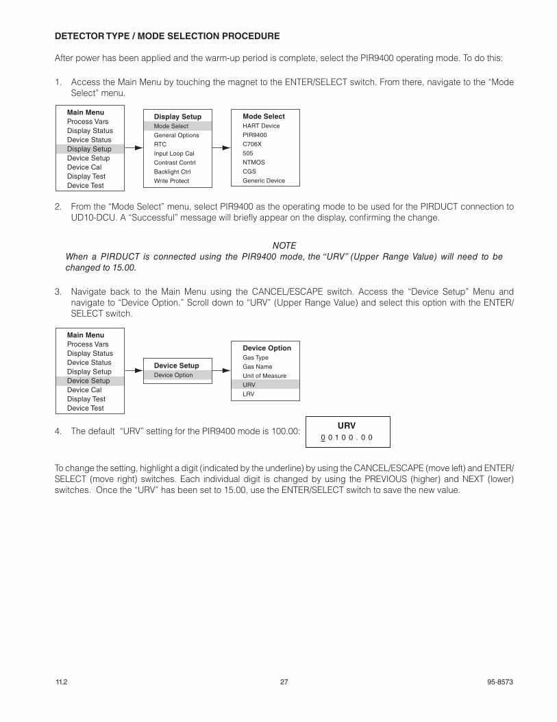
DETECTOR TYPE / MODE SELECTION PROCEDURE
After power has been applied and the warm-up period is complete, select the PIR9400 operating mode. To do this:
1. Access the Main Menu by touching the magnet to the ENTER/SELECT switch. From there, navigate to the “Mode Select” menu.
2. From the “Mode Select” menu, select PIR9400 as the operating mode to be used for the PIRDUCT connection to UD10-DCU. A “Successful” message will briefly appear on the display, confirming the change.
NOTEWhen a PIRDUCT is connected using the PIR9400 mode, the “URV” (Upper Range Value) will need to be changed to 15.00.
3. Navigate back to the Main Menu using the CANCEL/ESCAPE switch. Access the “Device Setup” Menu and navigate to “Device Option.” Scroll down to “URV” (Upper Range Value) and select this option with the ENTER/SELECT switch.
4. The default “URV” setting for the PIR9400 mode is 100.00:
To change the setting, highlight a digit (indicated by the underline) by using the CANCEL/ESCAPE (move left) and ENTER/SELECT (move right) switches. Each individual digit is changed by using the PREVIOUS (higher) and NEXT (lower)switches. Once the “URV” has been set to 15.00, use the ENTER/SELECT switch to save the new value.
Main MenuProcess VarsDisplay StatusDevice StatusDisplay SetupDevice SetupDevice CalDisplay TestDevice Test
Display SetupMode Select
General Options
RTC
Input Loop Cal
Contrast Contrl
Backlight Ctrl
Write Protect
Mode SelectHART Device
PIR9400
C706X
505
NTMOS
CGS
Generic Device
Main MenuProcess VarsDisplay StatusDevice StatusDisplay SetupDevice SetupDevice CalDisplay TestDevice Test
Device SetupDevice Option
Device OptionGas Type
Gas Name
Unit of Measure
URV
LRV
URV0 0 1 0 0 . 0 0

28 95-857311.2
S3 CONFIGURATION
1. Create a new DCU point with the correct LON address/point number.
2. Select “Ductwatch” as the detector type and enter all appropriate information in the DCU Editor.
Select Address/Point Number Window in S3
DCU Editor Window in S3

29 95-857311.2
CALIBRATION
To initiate calibration of the PIRDUCT from the UD10-DCU Display:
1. Use the magnet to activate the switches on the UD10-DCU display, navigate to the “Calibration” menu.
2. Activate “Execute” (ENTER/SELECT) to start calibration.
3. The UD10-DCU will display “Waiting for Zero” on the main display screen.
4. The UD10-DCU will then display “Waiting for Gas” on the screen.
5. Apply calibration gas to the PIRDUCT.
6. The UD10-DCU will continue to display “Waiting for Gas” on the screen.
7. When the UD10-DCU displays “Remove Cal Gas” on the screen, remove the calibration gas from the PIRDUCT.
8. The UD10-DCU automatically returns to the normal mode after successful calibration.
Main MenuProcess VarsDisplay StatusDevice StatusDisplay SetupDevice SetupDevice CalDisplay Test
Device CalCalibration
Cal Gas Conc
CalibrationExecute
Abort

95-8573
X3301 MultispectrumIR Flame Detector
FlexSonicTM Acoustic Leak Detector
PointWatch Eclipse® IR Combustible Gas Detector
FlexVu® Universal Display with GT3000 Toxic Gas Detector
Eagle Quantum Premier®
Safety System
Corporate Office6901 West 110th StreetMinneapolis, MN 55438 USAwww.det-tronics.com
Phone: +1 952.941.6665 Toll-free: +1 800.765.3473
Fax: [email protected]
Specifications subject to change without notice.
All trademarks are the property of their respective owners. © 2020 Detector Electronics Corporation. All rights reserved.
Det-Tronics manufacturing system is certified to ISO 9001— the world’s most recognized quality management standard.