instruction manuald163axztg8am2h.cloudfront.net/.../amicus-basic-manual-en.pdfplease read this...
TRANSCRIPT
From novice to professional, from defender to attacker,... ideal for every type of player and every level of play
Congratulations, you are now the owner of a Butterfly table tennis robot!
The manufacturer offers a full 2 year gu-arantee as well as a 5 year service plan covering repairs and replacement parts, effective from the date of purchase. Please ensure you keep your receipt!
Special features:1. Unique worldwide innovation: Ball delivery with state of the art three- wheel technology
2. The wheels are manufactured using rigid sponge with a special coating for better durability3. Compact, solid, functional construction (6kg)4. A large all-round collection net 5. Well designed and user-friendly control panel6. Variable ball placement, adjustable to desired spin, speed and trajectory 7. Automatic correction of length of ball delivery8. Adjustable height of ball delivery.
9. All functions adjustable directly from the player’s side on the control panelPlease note:9. Please read this instruction manual carefully before using the machine! 10. The Table Tennis Robot may only be connected to a 100-230V power supply 11. The projection wheels rotate at high speed therefore avoid touching the wheels while the machine is running as this can cause injury!12. The Table Tennis Robot, AMICUS BASIC, should only be used in closed and dry rooms!
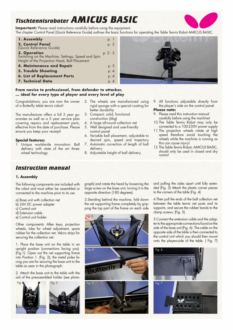
Important: Please read instructions carefully before using the equipment.The chapter Control Panel (Quick Reference Guide) outlines the basic functions for operating the Table Tennis Robot AMICUS BASIC.
1. Assembly p. 12. Control Panel p. 2(Quick Reference Guide)3. Operation p. 2 - 3Switching on the Machine, Settings, Speed and SpinHeight of the Projection Head, Ball Placement 4. Maintenance and Repair p. 35. Trouble Shooting p. 46. List of Replacement Parts p. 47. Technical Data p. 4
Instruction manual
1. Assembly
The following components are included with the robot and must either be assembled or connected to the machine prior to its use.
a) Base unit with collection netb) 24V DC power adapterc) Control unitd) Extension cablee) Control unit holder
Other components: Allen keys, projection wheels, tube for wheel adjustment, spare rubber for the collection net, Velcro strips for securing the collection net.
1. Place the base unit on the table in an upright position (connections facing you). (Fig.1). Open out the net supporting frame into Position 1. (Fig. 2); the metal poles fa-cing you are for securing the base unit to the table as seen in the photograph.
2. Attach the base unit to the table with the aid of the preassembled holder (see photo-
graph) and rotate the head by loosening the large screw on the base unit, turning it in the opposite direction (180 degrees).
3.Standing behind the machine, fold down the net supporting frame completely by grip-ping the top part of the frame on each side
and pulling the sides apart until fully exten-ded (Fig. 3) Attach the plastic corner pieces to the corners of the table (Fig. 4)
4.Then pull the ends of the ball collection net between the table tennis net posts and its supports, and secure the rubber bands to the clamp screws. (Fig. 5)
5.Connect the extension cable and the adap-ter to the appropriate connections found on the side of the base unit (Fig. 6). The cable on the opposite side of the table is then connected to the control unit which you should then mount onto the players-side of the table. ( Fig. 7)
Fig. 1 Fig. 2 Fig. 7Fig. 5
Fig. 3
Fig. 4 Fig. 6
Tischtennisroboter AMICUS BASIC

2. Control Panel (Quick Reference Guide)
With the help of rotary switches 1-6 above and the buttons, it is possible to program six different landing spots, for example Ball 1 Þ middle, Ball 2 Þ left, Ball 3 Þ right, Ball 4 Þ right … See illustration.
Button A: Switches from normal mode to two different random modesButton B: Optional activation of up to six balls (maximum)Button C: Enables you to reduce the ball dis-tribution from a maximum of six, down to one ball (minimum). Rotary switch I: Spin regulation (-4 extreme backspin; 0 no spin; 6 extreme topspin) Rotary switch II: Speed regulation (1 slow, 22 fast) Rotary switch III: Side spin regulation (left → Sidespin left; right → Sidespin right)Rotary switch IV: Trajectory regulation (lef t→ low trajectory; right → high trajectory)Rotary switch V: Regulation of the ball fre-quency (balls/min)
The six yellow indicator lights show how many balls are activated at any given time. The flashing light indicates which ball is next to be ejected. The green LED will only light up if one of the random functions is in operation (see below for more details)
Advice: When executing an exercise starting with service, both the trajectory and speed of the ball are to be adjusted in low position,
where as the height of the head in rather high position.
3. Operation
Switching on the MachineFill the “ball container”with a sufficient quantity of balls (50-60 balls) and then turn the Ball/min rotary switch to the “0” position before turning on the power.
After turning on the power, the robot will carry out a brief self test (approximately 5 seconds) and the control unit will then automatically switch to the basic setting. By turning the “Ball/min” rotary switch to a higher position the projection motors will start to work and the robot will start relea-sing balls.
Attention: If there are no balls inside the machine, it can take up to approximately 10 seconds (depending on the chosen ball frequency) until the first ball is released!
The height of the projection head As with all the Amicus robots, the height of the robot head can be adjusted as follows: Loosen the hand screw on the back of the tube which holds the projec-tion head. The tube can be moved up and down as required. (Fig. 8.). Finally
adjust to the desired height ensuring that the top of the outer tube lines up with one of the markings on the inner tube then tighten the hand screw (Fig. 9)
Ball Placement1. Ball delivery to a specific point on the tableAfter turning on the robot, the control unit
will automatically switch to the basic set-ting. The robot is now ready to deliver the balls to a specific point on the table. The landing spot can be continuously set using the rotary switch for left/right placement.
2. Programmed ball delivery to various points on the tableWith Button B „←“, at least two balls (maximum six) must be selected. Then va-rious targets can be chosen by means of the corresponding left/right switches. The flashing LEDs indicate which ball will be delivered next. By pressing Button C „ → “ the number of balls can be reduced. After the end of each “round” the ball delivery will commence again from the beginning.
3. “rnd” Random ball delivery to various points around a specific pointTo use the “rnd” function, press Button A. Again with Button B „←“, it is sufficient to activate a single ball (1 indicator light is activated) in order to activate the “rnd” random function. In this case, the robot dis-tributes the balls randomly within a 20cm
Fig. 9
Fig. 8
6 yellow 6 rotary switches Button A 2 greenindicator lights (left right) (programme/rnd/RND) indicator lights
rotary switch I. rotary switch II. rotary switch III. rotary switch IV.Spin regulation Speed regulation Sidespin regulation Trajectory regulation
Button C rotary switch V. Button Bball 6 to 1 Ball frequency ball 1 to 6
diameter circle of the set points, simulating a real match situation.
4. “RND” Random ball delivery to various points on the tableBy pressing Button A again, the RND function will be activated, however, with Button B „←“, at least two balls must be activated (two yellow indicator lights must be activated), selecting the various target points of the balls by turning the corres-ponding left/right switches. The balls will now be released at random. Again, a flas-hing LED will indicate which ball will be released next. By pressing Button C „ → “, individual balls can be cancelled. To exit the random function press Button C again.
5. Combining „RND” and „rnd”The Rnd and rnd functions can be com-bined by pressing Button A for a third time. Only one ball has to be activated with Button B „←“. In this case the set points are chosen at random (RND) and the balls will be delivered randomly within a 20cm diameter circle of the set points, simulating a real match situation.
Please Note: The AMICUS’ intelligence manages the length of each ball to be the same, inde-pendent from set position!
Ball characteristicsThe set Spin, Speed, Side-Spin and trajec-
tory apply for each programmed ball in the same way.
Ball-frequencyBy turning the „rotary switch V“ you can adjust the quantity of ejected balls per mi-nute.The AMICUS throws more balls out if the frequency is set higher.
Switch offDisconnect the power supply when the ro-bot is not used for a longer period of time; the AMICUS should never be left alone switched on.
4. Maintenance and Repair
Important: Always unplug from the mains before carrying out any mainte-nance or repairs.
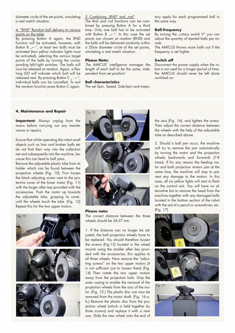
Ensure that whilst operating the robot small objects such as hair and broken balls etc do not find their way into the collection net and subsequently into the machine, be-cause this can lead to ball jams.Remove the adjustable plastic tube from its holder which can be found between the projection wheels (Fig. 10). First loosen the black adjusting screw next to the pro-tective cover of the lower motor (Fig. 11) with the larger allen key provided with the accessories. Push the motor up towards the adjustable tube, gripping its cover, until the wheels touch the tube. (Fig. 12) Repeat this for the two upper motors.
Please note: The correct distance between the three wheels should be 36-37 mm.
1. If the distance can no longer be ad-justed, the ball projection wheels have to be replaced. You should therefore loosen the screws (Fig.13) located in the wheel mounts using the smaller allen key provi-ded with the accessories; this applies to all three wheels. Now remove the “adjus-ting screws” on the two upper motors (it is not sufficient just to loosen them) (Fig. 14) Then rotate the two upper motors away from the projection hole. Grip the outer casing to enable the removal of the projection wheels from the axis of the mo-tor. (Fig. 15.) The plastic disc can now be removed from the motor shaft. (Fig. 16.a, b,) Remove the plastic disc from the pro-jection wheel (which is held together by three screws) and replace it with a new one. Slide the new wheel onto the end of
the axis (Fig. 16), and tighten the screw. Then adjust the correct distance between the wheels with the help of the adjustable tube as described above.
2. Should a ball jam occur, the machine will try to remove the jam automatically by turning the motor and the projection wheels backwards and forwards (7-8 times). If for any reason the feeding mo-tor and both projection motors jam at the same time, the machine will stop to pre-vent any damage to the motors. In this case, all six yellow lights will start to flash on the control unit. You will have no al-ternative but to remove the head from the machine together with any damaged balls located in the bottom section of the robot with the aid of a pencil or screwdriver, etc. (Fig. 17)
Fig. 13
Fig. 14
Fig. 15
Fig. 10
Fig. 11
Fig. 12
Fig. 16a
Fig. 16b
Fig. 17

6. List of Replacement Parts
List of Replacement Partsmobil-100 Base unit with collection netmobil -101 Robot headBASIC -102 Control unitmobil -103 Holder for control unit mobil -105 Extension cablemobil -106 Projection motor
mobil -107 Feeding motormobil -108 Oscillating head motor mobil -109 Motor for height adjustmentmobil -110 Projection wheelmobil -104 DC adapter (24V, 2.5A)mobil -111 Axis for projection wheel
mobil -112 Ball placement mechanism mobil -113 Motor casing (3 part)
Further replacement parts available upon request!
7. Technical Data
Mains Power Supply: 100-230V, 50-60 Hz transformer, approximately 40 WThe robot should only be operated indoors within a temperature range of 0-40°C.Weight: 6 kg (with net)Overall dimensions (with net): Height 0.75m; Width 0.28 m; Depth 0.25 m
The electrical adapter device was sub-ject to a test for the approval of electrical
appliances and was found to conform to the standard outlined below:
Conformity with the Low Voltage directive 73/23/EECAs last amended by EEC Directive 93/68/EECRegistration No.: AN 50091861 0001Report No.: 17004848 001
As is evident from Test Report Nos. NTEK-2010NT1115351E and NTEK-2010NT1115353SSThe robot AMICUS BASIC is permitted to bear the CE trademark.
Further product information and the product video are available on butterfly.tt/amicus
5. Error Management
Attention: If you are not able to resolve the problems with the help of this checklist, a specialist must be consulted! Please contact your specialist supplier or the Butterfly service centre (address is located on the side). Always contact a competent specialist
if the power cable is defective or if the fuse blows again immediately after being replaced. Failure to do so will invalidate your claim for a refund during the two year guarantee period
Problem Solution
The robot does not function once assem-bled
a) No power supply?b) Blown fuse → replace the fuse in the control unitCheck whether the cable plugs on the bottom of the control unit have been plugged in correctly.
Is Rotary Switch V for ball frequency set to „0“? → Turn it up.
Length of ball delivery is irregular.a) Check distance between the projection wheels, are the wheels worn?b) Incorrect assembly: Are the tubes and the robot head securely in place?c) The pin for regulating the length “is stuck” → lubricate it with some silicone.
The balls are suddenly being delivered irregularly and with varying length.
a) Restartb) A damaged ball or other foreign body is obstructing the transport of balls to the projection wheels → remove.A damaged ball or foreign body is obstructing the transport of balls to the projection wheels → remove.
Random function (RND) on the control unit cannot be activated; green indicator light does not light up.
At least two balls must be activated and at least two yellow indicator lights must be on.
Balls are stuck between the ball projec-tion wheels, the control unit switches itself off.
Pull out the adapter from the mains, remove all balls from between the projection wheels, then start the robot again.
Pin for regula-ting ball placement
Tamasu Butterfly Europa GmbH · Am Schürmannshütt 30h GERMANY · 47441 Moers · Tel: +49 2841 [email protected] · www.butterfly.tt www.facebook.com/butterfly.europe Amicus Video