instruction manualmateriel-physique.ens-lyon.fr/bdd/job/bdd/notices/n043-011.pdfinstruction manual...
TRANSCRIPT
@X4-0047-5
- 1 -
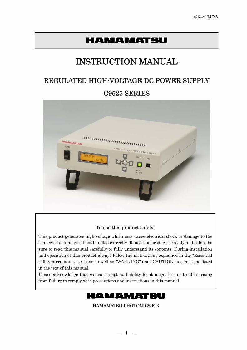
INSTRUCTION MANUAL
REGULATED HIGH-VOLTAGE DC POWER SUPPLY
C9525 SERIES
HAMAMATSU PHOTONICS K.K.
To use this product safely:
This product generates high voltage which may cause electrical shock or damage to the connected equipment if not handled correctly. To use this product correctly and safely, be sure to read this manual carefully to fully understand its contents. During installation and operation of this product always follow the instructions explained in the "Essential safety precautions" sections as well as "WARNING" and "CAUTION" instructions listed in the text of this manual. Please acknowledge that we can accept no liability for damage, loss or trouble arising from failure to comply with precautions and instructions in this manual.

@X4-0047-5
- 2 -
Safety alert symbols and signal words
The following safety alert symbols and signal words are used in this manual and in warning
labels on the product to alert you to caution points when using this product. Make
sure you fully understand the meaning of each signal word and comply with the
instructions.
Alert symbol and signal words
WARNING
"WARNING" indicates a potentially hazardous situation which, if not avoided, could result in death or serious injury.
CAUTION
"CAUTION" indicates a potentially hazardous situation which, if not avoided, could result in minor or moderate injury or damage to the equipment or software.
Pictorial signs
Electrical shock hazard A high voltage is present.
Protective ground terminal
AC (Alternating current)
Power ON
Power OFF

@X4-0047-5
- 3 -
Essential safety precautions
WARNING
■ Do not remove the cover of this product.
Do not remove the cover and panels of this product. Do not disassemble or modify any part of this product. Doing so may cause electrical shock or fire. Before connecting or disconnecting the cables from the equipment, always first turn off the power switch. Touching internal parts while the power is still supplied is hazardous and can result in electrical shock.
■ Warnings when handling the power supply
Use the AC power cable that comes with this product.
Always connect the AC power cable to a grounded 3-prong AC outlet. Using a non-grounded AC outlet or extension cord with no ground wire will disable the protective function and increase the risk of electrical shock or fire. If connecting to a 3-prong AC outlet is not possible, use the supplied 3P/2P converter plug and securely ground the unit by using the grounding lead coming out of the 3P/2P converter.
Do not cut the protective grounding wire in this product or AC power cable. Do not remove the wire on the protective grounding terminal. Doing so may cause electrical shock or fire.
When plugging or unplugging the power cable, always first make sure that the power switch is off and then push or pull gently while gripping the plug itself. Do not push or pull on the cable itself. At this point, avoid handling the cable with wet hands. Doing so may cause electrical shock or malfunctions.
Do not scratch, damage or tamper with the cable and avoid placing any heavy objects on it. Operating with a damaged cable may result in electrical shock or fire.
When using the high-voltage output receptacle, always keep a high-voltage output cable with an SHV plug connected to that receptacle. Failure to do so may cause electrical shock if a high voltage is accidentally applied.
If using a high-voltage cable instead of the high-voltage output cable that was supplied, make sure the cable can withstand more than the required high voltage. Using a cable with a low breakdown voltage may cause electrical shock or malfunctions.
When a high voltage is applied, never touch the high-voltage output receptacle of this product or high voltage parts of the connected equipment with bare hands or conductive items. Touching such parts is extremely hazardous and can result in electrical shock.
When plugging or unplugging the high-voltage output cable with an SHV plug, always first make sure the high voltage output is off. Malfunctions may occur if the high voltage output is on.
For the protection and safe use of the product and the system controlled by it, be sure to
follow the instructions and precautions on safety that are stated in this manual whenever you handle the product. Take special note that if you handle the product in a manner that violates these instructions, the protection functionality of the product may be damaged or

@X4-0047-5
- 4 -
impaired. In such cases, HAMAMATSU does not guarantee the quality, performance, function, and safety of product.
CAUTION
■ Warnings about the installation environment
This equipment is designed and tested for use in an industrial environment.
If this equipment is used in residential areas, EMI (electro-magnetic interference) may occur.
This equipment must not be used in residential areas.
Always use this product within the operating temperature range specified in this manual. Avoid installing this product in such a way that the air vents on the top and bottom of this product are blocked or air flow is prevented or ambient temperature rises excessively. Operation in such locations may result in fire.
Always use this product within the operating humidity range specified in this manual. Use caution when moving this product to a room where the humidity changes, since condensation may occur. Do not handle the product with wet hands since this may cause electrical shock or fire.
Do not operate this product in locations exposed to excessive dust, splashing from liquid such as water droplets, vibration or fire. Operating it in such locations may result in fire.
Do not operate this product in locations where flammable or explosive gases or vapors are present. Operation in such locations is extremely dangerous since it may cause explosions or fire.
Do not insert metal objects or inflammable material into the air vent holes. Be careful not to spill water on the product case. Doing so may cause electrical shock or fire.
Do not place this product on an unstable surface. Otherwise the product may fall over and cause bodily injury.
■ Warnings on abnormal operation
If smoke, fire or unusual odors are noticed while operating this product, immediately turn off the power switch and unplug the power cable from the AC outlet. Also check that no other equipment has caught fire and then consult our sales office.
■ Warnings of discarding
The material in the C9525 contains a lead and its compound. Please follow the applicable regulations regarding disposal of hazardous materials and industrial wastes in your country, state, region or province.
@X4-0047-5
- 5 -
Table of Contents
1. Overview ................................................................................................................................. 6 2. Ratings and Specifications ................................................................................................... 6 3. Accessories............................................................................................................................ 7 4. Part names and Descriptions ............................................................................................... 8
4.1. Front panel ...................................................................................................................... 8 4.2. Rear panel ....................................................................................................................... 9 4.3. Air intake vents ............................................................................................................ 10
5. How to Operate .................................................................................................................... 11 5.1. Preparation before power-on ...................................................................................... 11 5.2. Making settings by panel key (Local mode) .............................................................. 12 5.3. Operation by the remote (Usage of sample program) ................................................ 14 5.4. Operation by the remote(Various setting by commands) ...................................... 18 5.5. Alarm display ................................................................................................................ 32
6. Maintenance and Inspection .............................................................................................. 33 6.1. Maintenance and inspection ................................................................................... 33 6.2. Repair ............................................................................................................................ 33
7. Dimensional Outline ............................................................................................................ 34 8. Warranty ............................................................................................................................... 35

@X4-0047-5
- 6 -
1. Overview
The C9525 series is a regulated high-voltage DC power supply providing a maximum output up to 2 kV and 1.8 mA (Polarity changes by a suffix.). The all-solid-state circuit configuration using a DC-DC converter ensures high stability and reliability. The output voltage can be continuously adjusted from 0 V through the maximum and is displayed on the 4-digit panel meter with high accuracy. An SHV receptacle for output on the rear panel can be used to operate a photomultiplier tube, proportional counter tube and other devices requiring a stable source of DC high voltage. The C9525 is controllable from a PC (personal computer) using the USB cable that comes supplied with the C9525.
2. Ratings and Specifications
・Input line voltage 100 to 240 V AC ± 10 % ・Input line frequency (50 / 60 Hz) ±1 Hz ・Power consumption 60 VA max(at maximum output and AC input 264V/60Hz)
・High voltage power supply section
· Output voltage range C9525-02, -03 C9525-52,-53
0 V to -2000 V DC (guaranteed range: -320 to -2000 V) 0 V to +2000 V DC (guaranteed range: +320 to +2000 V)
· Maximum output current 1.8 mA · Line regulation Within ±(0.005 % +10 mV) for ±10 % line voltage change · Load regulation Within ±(0.03 % +50 mV) for 0 to 100 % load change · Ripple(Typ.) 0.003% +20 mV p-p (at maximum output)
(including induction hum) · Long-term stability(Typ.) ±(0.02 % +10 mV) per 8 hours (after one hour of preheat) · Temperature coefficient(Typ.) 0.01 %/C · Protection circuit Uses constant current circuit to protect from overload or short
circuit. Automatic reset · High voltage output receptacle SHV receptacle (rear) × 1 · High voltage output display 4-digit LCD · Voltage display accuracy Within ±(0.1 % +2 V)
・±5 V power supply section
· Output voltage range ±4.75 V to ±5.25 V (fixed) · Maximum output current 500 mA · Line regulation Within ±0.1 % for ±10 % input voltage change · Load regulation Within ±1 % for 0 to 100 % load change · Ripple Within ±0.06 %p-p · Drift Within ±0.05 %/h (after 30 minutes of preheat) · Temperature coefficient Within ±0.01 %/C
・±15 V power supply section
· Output voltage range ±14.25 V to ±15.75 V (fixed) · Maximum output current 200 mA · Line regulation Within ±0.1 % for ±10 % input voltage change · Load regulation Within ±0.5 % for 0 to 100 % load change · Ripple Within ±0.02 %p-p · Drift Within ±0.05 %/h (after 30 minutes of preheat)
@X4-0047-5
- 7 -
· Temperature coefficient Within ±0.05 %/C ・Operating temperature and humidity range 0 C to +40 C, below 90 % RH (no condensation) ・Performance guaranteed termperature and
humidity range +5 C to +35 C, below 80 % RH (no condensation)
・Storage temperature and humidity range -20 C to +60 C, below 85 % RH (no condensation) ・Dimensions 246 (W) × 70 (H) × 312 (D) mm ・Mass Approx. 3 kg ・Usage environment Location : Indoor
Altitude : Below 2000 meters Overvoltage category : II Pollution degree : 2 IP code : IP20
・Applicable safety standards EMC directive Safety standard
IEC61326-1:2005 Group 1, Class A IEC61010-1:2010
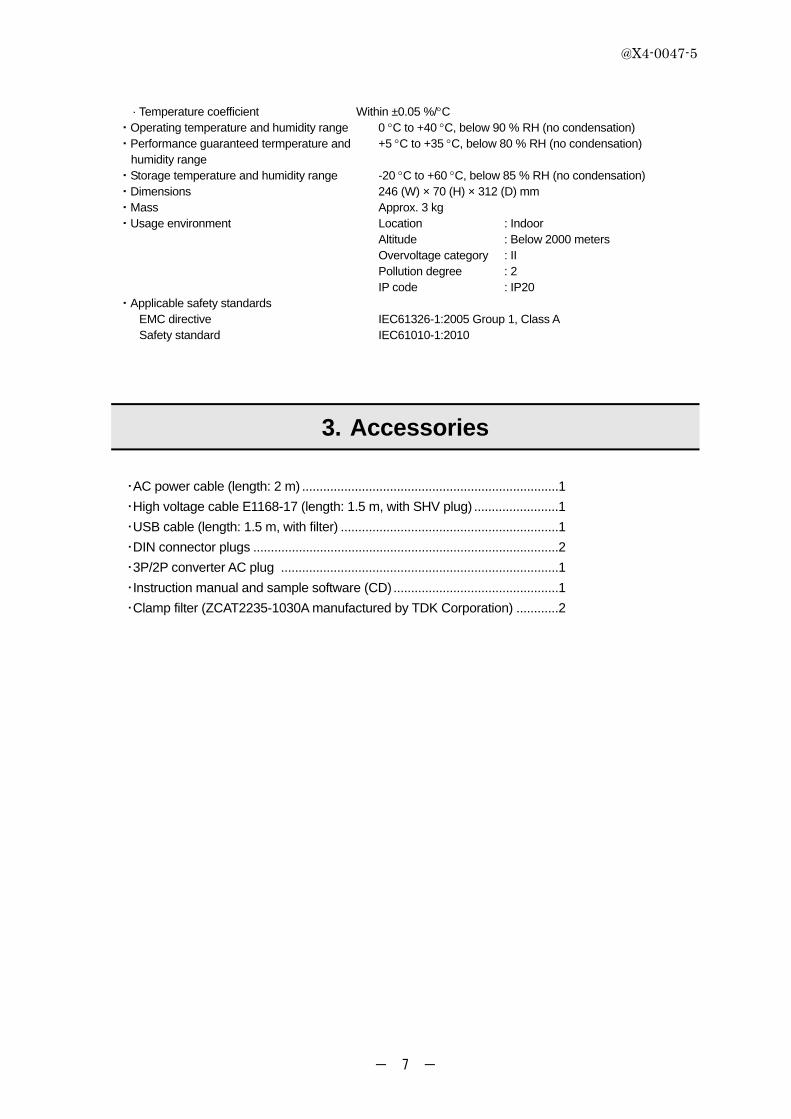
3. Accessories
・AC power cable (length: 2 m) ......................................................................... 1
・High voltage cable E1168-17 (length: 1.5 m, with SHV plug) ........................ 1
・USB cable (length: 1.5 m, with filter) .............................................................. 1
・DIN connector plugs ....................................................................................... 2
・3P/2P converter AC plug ............................................................................... 1
・Instruction manual and sample software (CD) ............................................... 1
・Clamp filter (ZCAT2235-1030A manufactured by TDK Corporation) ............ 2
@X4-0047-5
- 8 -
4. Part names and Descriptions
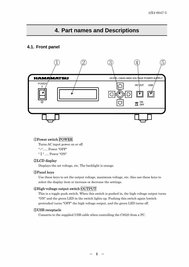
4.1. Front panel
① ② ③ ④ ⑤
①Power switch POWER Turns AC input power on or off.
"○"….. Power "OFF"
"┃" …. Power "ON"
②LCD display Displays the set voltage, etc. The backlight is orange.
③Panel keys Use these keys to set the output voltage, maximum voltage, etc. Also use these keys to
select the display item or increase or decrease the settings.
④High-voltage output switch OUTPUT This is a toggle push switch. When this switch is pushed in, the high voltage output turns
"ON" and the green LED in the switch lights up. Pushing this switch again (switch
protrudes) turns "OFF" the high voltage output, and the green LED turns off.
⑤USB receptacle Connects to the supplied USB cable when controlling the C9525 from a PC.
@X4-0047-5
- 9 -
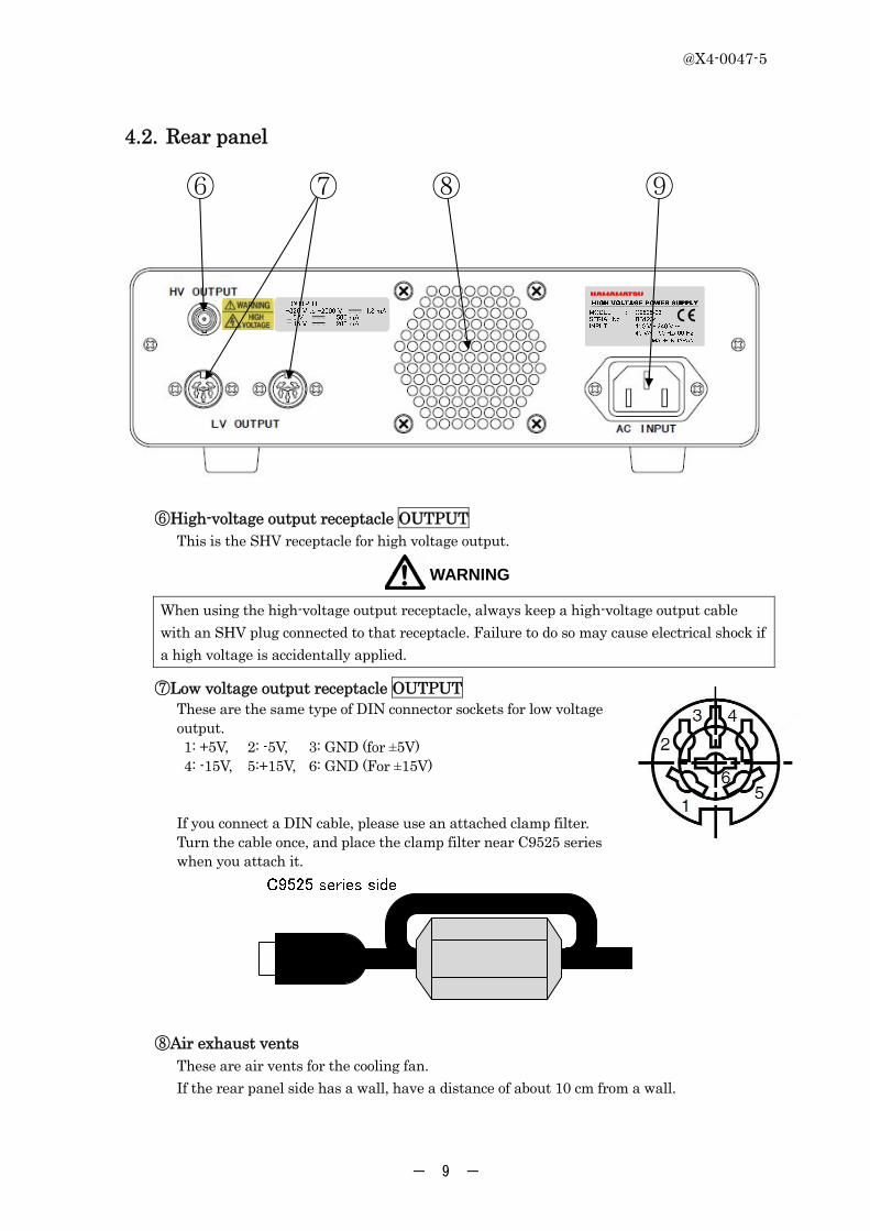
4.2. Rear panel
⑥ ⑦ ⑧ ⑨
⑥High-voltage output receptacle OUTPUT This is the SHV receptacle for high voltage output.
WARNING
When using the high-voltage output receptacle, always keep a high-voltage output cable
with an SHV plug connected to that receptacle. Failure to do so may cause electrical shock if
a high voltage is accidentally applied.
⑦Low voltage output receptacle OUTPUT These are the same type of DIN connector sockets for low voltage output. 1: +5V, 2: -5V, 3: GND (for ±5V) 4: -15V, 5:+15V, 6: GND (For ±15V) If you connect a DIN cable, please use an attached clamp filter. Turn the cable once, and place the clamp filter near C9525 series when you attach it.
⑧Air exhaust vents These are air vents for the cooling fan.
If the rear panel side has a wall, have a distance of about 10 cm from a wall.

@X4-0047-5
- 10 -
⑨AC power inlet LINE INPUT Connects to the supplied AC power cable.
WARNING
Connect the AC power cable to a grounded 3-prong AC outlet. The wrong connection may
cause electrical shock or fire.
4.3. Air intake vents
Air intake vents are provided on the upper cover of
this product. Do not block these vents or drop
foreign objects through these vents.
@X4-0047-5
- 11 -
5. How to Operate
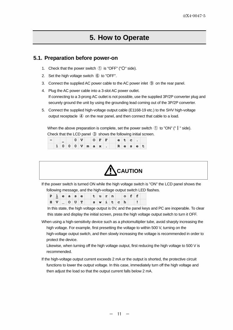
5.1. Preparation before power-on
1. Check that the power switch ① is "OFF" ("○" side).
2. Set the high voltage switch ⑥ to "OFF".
3. Connect the supplied AC power cable to the AC power inlet ⑨ on the rear panel.
4. Plug the AC power cable into a 3-slot AC power outlet.
If connecting to a 3-prong AC outlet is not possible, use the supplied 3P/2P converter plug and
securely ground the unit by using the grounding lead coming out of the 3P/2P converter.
5. Connect the supplied high-voltage output cable (E1168-19 etc.) to the SHV high-voltage
output receptacle ④ on the rear panel, and then connect that cable to a load.
When the above preparation is complete, set the power switch ① to "ON" ("┃" side).
Check that the LCD panel ③ shows the following initial screen.
- 0 V O F F e t c .
1 0 0 0 V m a x . R e s e t
CAUTION
If the power switch is turned ON while the high voltage switch is "ON" the LCD panel shows the
following message, and the high-voltage output switch LED flashes.
P l e a s e t u r n o f f
H V _ O U T s w i t c h !
In this state, the high voltage output is 0V, and the panel keys and PC are inoperable. To clear
this state and display the initial screen, press the high voltage output switch to turn it OFF.
When using a high-sensitivity device such as a photomultiplier tube, avoid sharply increasing the
high voltage. For example, first presetting the voltage to within 500 V, turning on the
high-voltage output switch, and then slowly increasing the voltage is recommended in order to
protect the device.
Likewise, when turning off the high voltage output, first reducing the high voltage to 500 V is
recommended.
If the high-voltage output current exceeds 2 mA or the output is shorted, the protective circuit
functions to lower the output voltage. In this case, immediately turn off the high voltage and
then adjust the load so that the output current falls below 2 mA.

@X4-0047-5
- 12 -
5.2. Making settings by panel key (Local mode)
■ Display items and initial values - 0 V O F F e t c .
1 0 0 0 V m a x . R e s e t
1) High voltage (upper left): 0V, OFF, cursor position (100ths digit)
2) Maximum voltage (lower left): 1000 V max.
3) etc. (upper right)
1. LCD contrast: 5 (adjustable from 0 to 9)
2. LCD backlight: ON
3. High voltage switch LED: ON
4) Reset (lower right)
■ How to use the panel keys
1) Press the Up/Down keys to increase or decrease the value of
the display item where the cursor is positioned. Use the
Right/Left keys to move the cursor to another digit of the
display item.
2) To move the cursor to another item on the LCD, hold down the
SET key in the center between the panel keys long enough.
The cursor then moves to another display item in the specified order (1→2→3→4→1).
When the cursor has moved to the target item, release the SET button.
The display might freeze if you rapidly repeat pressing the same key since it cannot
keep up pace with your setting speed. If that happens, press another key to restore the
normal state.
■ To set a high voltage
1) On the initial screen after the power is turned on, the cursor appears on the 100ths
digit of the high voltage item.
- 0 V O F F e t c .
1 0 0 0 V m a x . R e s e t
2) Press the Up/Down keys to increase or decrease the voltage value. Use the Right/Left
keys to move the cursor to another digit.
Any value exceeding the maximum voltage cannot be set.
3) When the desired high voltage is displayed, the setting is complete. There is no need
to press the SET key.
4) Press the high-voltage output switch to turn it on.
The LCD display turns on and the green LED in the switch lights up.
Note that the green LED does not light up if the high-voltage output switch LED is set
to OFF.
@X4-0047-5
- 13 -
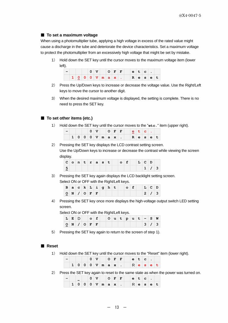
■ To set a maximum voltage When using a photomultiplier tube, applying a high voltage in excess of the rated value might
cause a discharge in the tube and deteriorate the device characteristics. Set a maximum voltage
to protect the photomultiplier from an excessively high voltage that might be set by mistake.
1) Hold down the SET key until the cursor moves to the maximum voltage item (lower
left).
- 0 V O F F e t c .
1 0 0 0 V m a x . R e s e t
2) Press the Up/Down keys to increase or decrease the voltage value. Use the Right/Left
keys to move the cursor to another digit.
3) When the desired maximum voltage is displayed, the setting is complete. There is no
need to press the SET key.
■ To set other items (etc.)
1) Hold down the SET key until the cursor moves to the "etc." item (upper right).
- 0 V O F F e t c .
1 0 0 0 V m a x . R e s e t
2) Pressing the SET key displays the LCD contrast setting screen.
Use the Up/Down keys to increase or decrease the contrast while viewing the screen
display.
C o n t r a s t o f L C D
5 1 / 3
3) Pressing the SET key again displays the LCD backlight setting screen.
Select ON or OFF with the Right/Left keys.
B a c k L i g h t o f L C D
O N / O F F 2 / 3
4) Pressing the SET key once more displays the high-voltage output switch LED setting
screen.
Select ON or OFF with the Right/Left keys.
L E D o f O u t p u t - S W
O N / O F F 3 / 3
5) Pressing the SET key again to return to the screen of step 1).
■ Reset
1) Hold down the SET key until the cursor moves to the "Reset" item (lower right).
- 0 V O F F e t c .
1 0 0 0 V m a x . R e s e t
2) Press the SET key again to reset to the same state as when the power was turned on.
- 0 V O F F e t c .
1 0 0 0 V m a x . R e s e t
@X4-0047-5
- 14 -
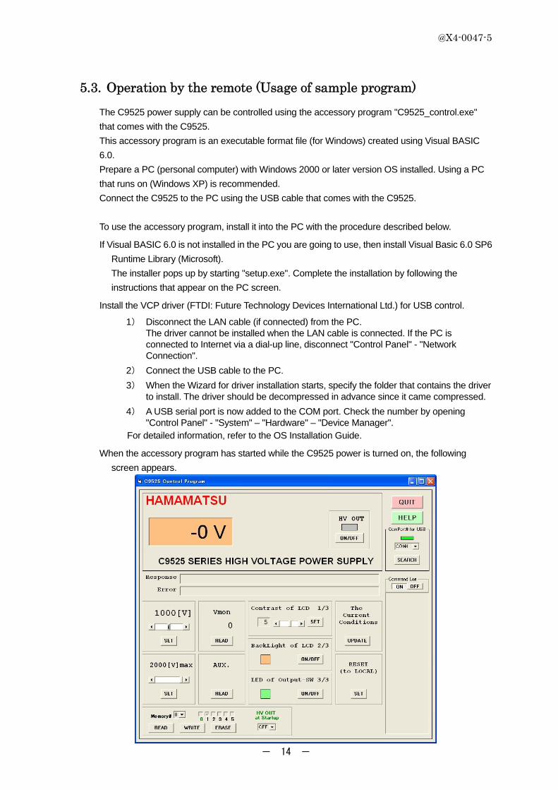
5.3. Operation by the remote (Usage of sample program)
The C9525 power supply can be controlled using the accessory program "C9525_control.exe"
that comes with the C9525.
This accessory program is an executable format file (for Windows) created using Visual BASIC
6.0.
Prepare a PC (personal computer) with Windows 2000 or later version OS installed. Using a PC
that runs on (Windows XP) is recommended.
Connect the C9525 to the PC using the USB cable that comes with the C9525.
To use the accessory program, install it into the PC with the procedure described below.
If Visual BASIC 6.0 is not installed in the PC you are going to use, then install Visual Basic 6.0 SP6
Runtime Library (Microsoft).
The installer pops up by starting "setup.exe". Complete the installation by following the
instructions that appear on the PC screen.
Install the VCP driver (FTDI: Future Technology Devices International Ltd.) for USB control.
1) Disconnect the LAN cable (if connected) from the PC. The driver cannot be installed when the LAN cable is connected. If the PC is connected to Internet via a dial-up line, disconnect "Control Panel" - "Network Connection".
2) Connect the USB cable to the PC.
3) When the Wizard for driver installation starts, specify the folder that contains the driver to install. The driver should be decompressed in advance since it came compressed.
4) A USB serial port is now added to the COM port. Check the number by opening "Control Panel" - "System" – "Hardware" – "Device Manager".
For detailed information, refer to the OS Installation Guide.
When the accessory program has started while the C9525 power is turned on, the following
screen appears.

@X4-0047-5
- 15 -
The C9525 can be controlled by using the buttons and slide bars on this screen.
■ To set a high voltage Clicking the small arrows at the ends of the horizontal scroll bar changes the
voltage value in ±1 V steps and clicking the slide bar changes the voltage
value in ±100 V steps. The upper voltage setting is limited by the maximum
voltage setting. After adjusting to the desired high voltage, click the SET
button to enable that setting.
■ To set a maximum voltage Clicking the small arrows at the ends of the horizontal scroll bar changes the
voltage value in ±1 V steps and clicking the slide bar changes the voltage
value in ±100 V steps. After adjusting to the desired high voltage, click the
SET button to enable that setting.
■ To set the step voltage Clicking the small arrows at the ends of the horizontal scroll bar changes the
voltage value in ±1 V steps and clicking the slide bar changes the voltage
value in ±100 V steps. After adjusting to the desired step voltage, click the
SET button to enable it.
■ To read the monitor voltage Vmon Click the READ button under "Vmon" to read and display the monitor voltage.
■ To read the low-voltage power supply voltages Click the READ button under "AUX" to read the low voltages (±5V and ±15V)
output from the connector on the rear panel.
The voltage values are shown in the Response box.
■ To set the LCD contrast Move the horizontal slide bar to adjust the LCD contrast.
After adjusting the contrast, click the SET button to enable that
contrast.
■ To set the LCD backlight to ON/OFF Click the ON/OFF button to switch the backlight on or off.
■ To set the high-voltage output switch LED to ON/OFF Click the ON/OFF button to switch the LED on or off.

@X4-0047-5
- 16 -
■ To read the currently set values Click the UPDATE button to read and display the currently set values.
■ To reset Click the SET button to return to the same state as when the power was turned
on. (This enters Local mode that also allows panel key operation.)
■ To control the high voltage output Click the ON/OFF button to turn on or off the high voltage output that was set.
■ To read, write, or erase the setting (flash memory) Any setting can be stored in a flash memory (0 to 5).
Memory # 0 is selected at the time of startup. High voltage can
also be output (ON) at startup.
Select the desired memory # and click the READ or WRITE or
ERASE button as needed.
To erase the settings stored in all memories, select “A” and click the ERASE button.
■ To read the information Click the “Read Inf.” button to read Type No. , Serial No. and Firmware Revision.
The information is shown in the Response box.
■ To display the command log Click the ON button to display the send/receive commands used to make various settings. You
may refer to this log when creating control commands on your own. Press the OFF button to
hide the log.
■ To search for the VCP number used for USB Click the SEARCH button to search for the VCP number.
This function is available on Windows 2000 or later versions.
If your PC uses an earlier Windows version, enter the VCP number.
■ To quit the program (QUIT) Click the QUIT button to reset and exit the control program.
Remote mode will not be released if the program was terminated without
using this QUIT button. To next use the C9525 in Local mode, use the panel
keys to enter Local mode (See below).
■ To display the help screen (HELP) Click the HELP button to display the Help screen.
You can refer to the instructions in Help on how to use this program and
control command list.
@X4-0047-5
- 17 -
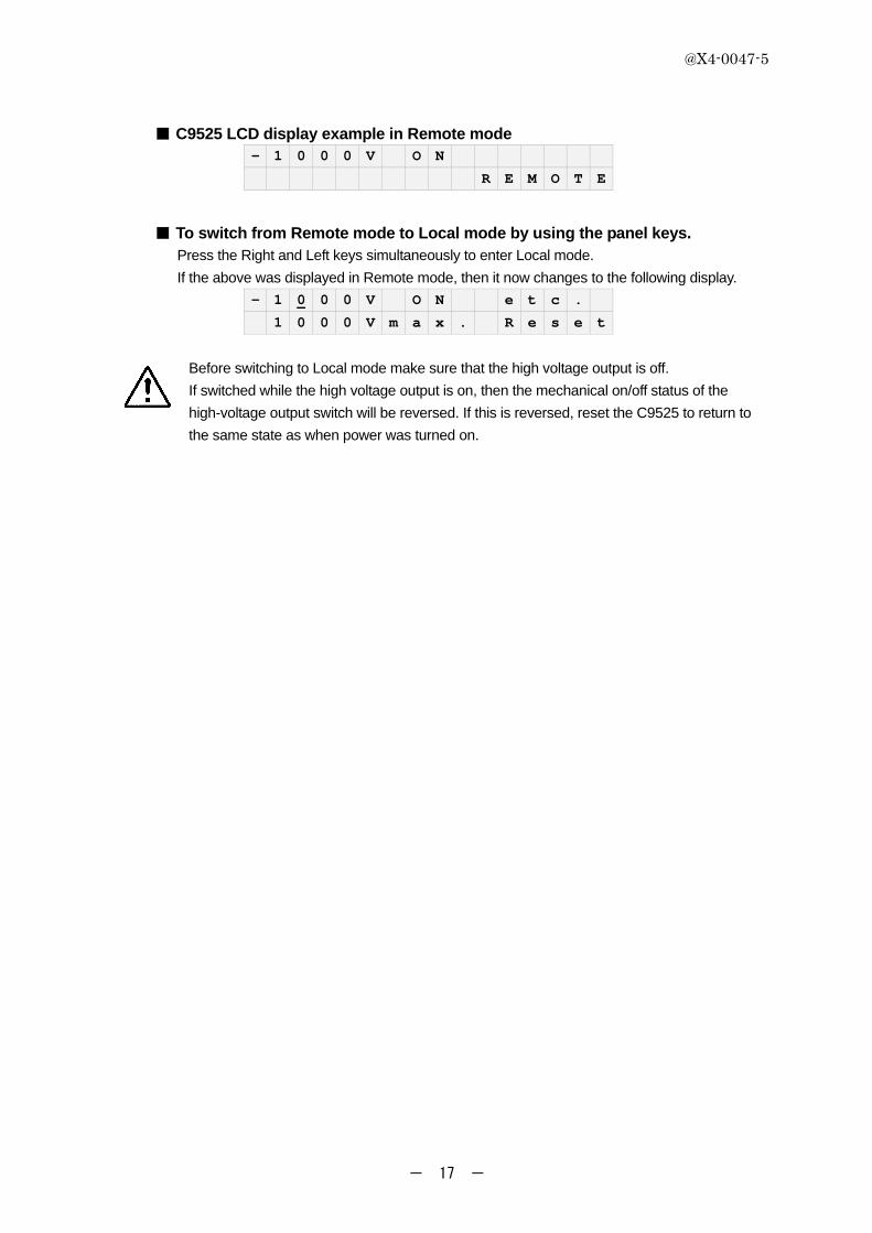
■ C9525 LCD display example in Remote mode - 1 0 0 0 V O N
R E M O T E
■ To switch from Remote mode to Local mode by using the panel keys. Press the Right and Left keys simultaneously to enter Local mode.
If the above was displayed in Remote mode, then it now changes to the following display.
- 1 0 0 0 V O N e t c .
1 0 0 0 V m a x . R e s e t
Before switching to Local mode make sure that the high voltage output is off.
If switched while the high voltage output is on, then the mechanical on/off status of the
high-voltage output switch will be reversed. If this is reversed, reset the C9525 to return to
the same state as when power was turned on.

@X4-0047-5
- 18 -
5.4. Operation by the remote(Command Set)
When creating your own program by utilizing control commands, the following command
is available. In all commands, it is necessary to be terminated by CR(Carriage Return). Refer to the control command list shown below.
Success Failure
Set the high voltage output V<value1><value2><CR>value1:0h~14hvalue2:0h~63h
VA BC,BA
Set the maximum voltage M<value1><value2><CR>value1:0h~14hvalue2:0h~63h
VA BC,BA
Set the step voltage S<value1><value2><CR>value1:0h~14hvalue2:0h~63h
VA BC,BA
Set LCD Contrast C<value><CR> value:0h~9h VA BC,BASet the high voltage output ON/OFF O<value><CR> value:0h or 1h VA BC,BASet LCD backlight ON/OFF B<value><CR> value:0h or 1h VA BC,BASet the high voltage output switch LED ON/OFF L<value><CR> value:0h or 1h VA BC,BASet device mode : remote or local Q<value><CR> value:0h or 1h VA BC,BARead the device setting R<CR> None 13 byte data BCRead the high voltage monitor value T<CR> None 2 byte data BCRead the low voltage output (±5V,±15V) A<CR> None 8 byte data BCReset the device to the condition at power-on. D<CR> None VA BCRead Information F<CR> None 24 byte data BC
Operation Command ArgumentResponse
The communication setting of RS-232C is as follows: Baud rate : 9600 bit per second Data length : 8 bits Parity bit : None Stop bit : 1 bit Flow control : None The details of each command are described from the next page.

@X4-0047-5
- 19 -
■High voltage output setting
You can set the high voltage output. The command length of the high voltage setting is 4 byte.
Syntax: V<value1><value2><CR> Notes:
Input value1 and value2 in binary. The range of value1 is from 0 to 20. The range of value2 is from 0 to 99. High voltage output = <value1> x 100 + <value2> High voltage output is limited to maximum voltage or less. As shown below, the command line can be also described in binary. <56h><value1><value2><0Dh> ※hexadecimal representation
For example, in the case of Visual Basic, when you want to set the high voltage output at 1000V, you can write as follows; Dim Cmd Cmd = “V” + Chr(10) + Chr(0) + Chr(13) or Dim Cmd(3) As Byte Cmd(0) = 86 : Cmd(1) =10 : Cmd(2) = 0 : Cmd(3) = 13
Response: command success ⇒ “VA”(Valid Argument) is returned.
command failure Bad Command
⇒ “BC” is returned. Bad Argument
⇒ “BA” is returned.

@X4-0047-5
- 20 -
■Maximum voltage setting
You can set the maximum voltage. The command length of the maximum voltage setting is 4 byte.
Syntax: M<value1><value2><CR> Notes:
Input value1 and value2 in binary. The range of value1 is from 0 to 20. The range of value2 is from 0 to 99. Maximum voltage = <value1> x 100 + <value2>
Maximum voltage is limited to 2000V or less. As shown below, the command line can be also described in binary. <4Dh><value1><value2><0Dh> ※hexadecimal representation
For example, in the case of Visual Basic, when you want to limit the high voltage output to 1000V or less, you can write as follows; Dim Cmd Cmd = “M” + Chr(10) + Chr(0) + Chr(13) or Dim Cmd(3) As Byte Cmd(0) = 77 : Cmd(1) =10 : Cmd(2) = 0 : Cmd(3) = 13
Response: command success ⇒ “VA”(Valid Argument) is returned.
command failure Bad Command
⇒ “BC” is returned. Bad Argument
⇒ “BA” is returned.

@X4-0047-5
- 21 -
■Step voltage setting
You can set step voltage value. The command length of the step voltage value setting is 4 byte.
Syntax: S<value1><value2><CR> Notes:
Input value1 and value2 in binary. The range of value1 is from 0 to 20. The range of value2 is from 0 to 99. Step voltage = <value1> x 100 + <value2>
Step voltage is limited to maximum voltage value or less. As shown below, the command line can be also described in binary. <53h><value1><value2><0Dh> ※hexadecimal representation
For example, in the case of Visual Basic, when you want to set the step voltage of 100V, you can write as follows; Dim Cmd Cmd = “S” + Chr(1) + Chr(0) + Chr(13) or Dim Cmd(3) As Byte Cmd(0) = 83 : Cmd(1) =1 : Cmd(2) = 0 : Cmd(3) = 13
Response: command success ⇒ “VA”(Valid Argument) is returned.
command failure Bad Command
⇒ “BC” is returned. Bad Argument
⇒ “BA” is returned.

@X4-0047-5
- 22 -
■LCD contrast setting
You can set LCD contrast of a display for the device. The command length of the LCD contrast setting is 3 byte.
Syntax: C<value><CR> Notes: Input value in binary. The range of value is from 0 to 9. As shown below, the command line can be also described in binary. <43h><value><0Dh> ※hexadecimal representation
For example, in the case of Visual Basic, when you want to set a default LCD contrast, you can write as follows; Dim Cmd Cmd = “C” + Chr(5) + Chr(13) or Dim Cmd(2) As Byte Cmd(0) = 67 : Cmd(1) =5 : Cmd(2) =13
Response: command success ⇒ “VA”(Valid Argument) is returned.
command failure Bad Command
⇒ “BC” is returned. Bad Argument
⇒ “BA” is returned.

@X4-0047-5
- 23 -
■High voltage output ON/OFF setting
You can set high voltage output ON/OFF. The command length of the high voltage output ON/OFF setting is 3 byte.
Syntax: O<value><CR> Notes: Input value in binary. The value is 0 or 1. (0 : OFF, 1 : ON) As shown below, the command line can be also described in binary. <4Fh><value><0Dh> ※hexadecimal representation
For example, in the case of Visual Basic, when you want to turn the high voltage output on, you can write as follows; Dim Cmd Cmd = “O” + Chr(1) + Chr(13) or Dim Cmd(2) As Byte Cmd(0) = 79 : Cmd(1) =1 : Cmd(2) =13
Response: command success ⇒ “VA”(Valid Argument) is returned.
command failure Bad Command
⇒ “BC” is returned. Bad Argument
⇒ “BA” is returned.

@X4-0047-5
- 24 -
■LCD backlight ON/OFF setting
You can set the LCD backlight ON/OFF. The command length of the LCD backlight ON/OFF setting is 3 byte.
Syntax: B<value><CR> Notes: Input value in binary. The value is 0 or 1. (0 : OFF, 1 : ON) As shown below, the command line can be also described in binary. <42h><value><0Dh> ※hexadecimal representation
For example, in the case of Visual Basic, when you want to turn the LCD backlight off, you can write as follows; Dim Cmd Cmd = “B” + Chr(0) + Chr(13) or Dim Cmd(2) As Byte Cmd(0) = 66 : Cmd(1) =0 : Cmd(2) =13
Response: command success ⇒ “VA”(Valid Argument) is returned.
command failure Bad Command
⇒ “BC” is returned. Bad Argument
⇒ “BA” is returned.
@X4-0047-5
- 25 -
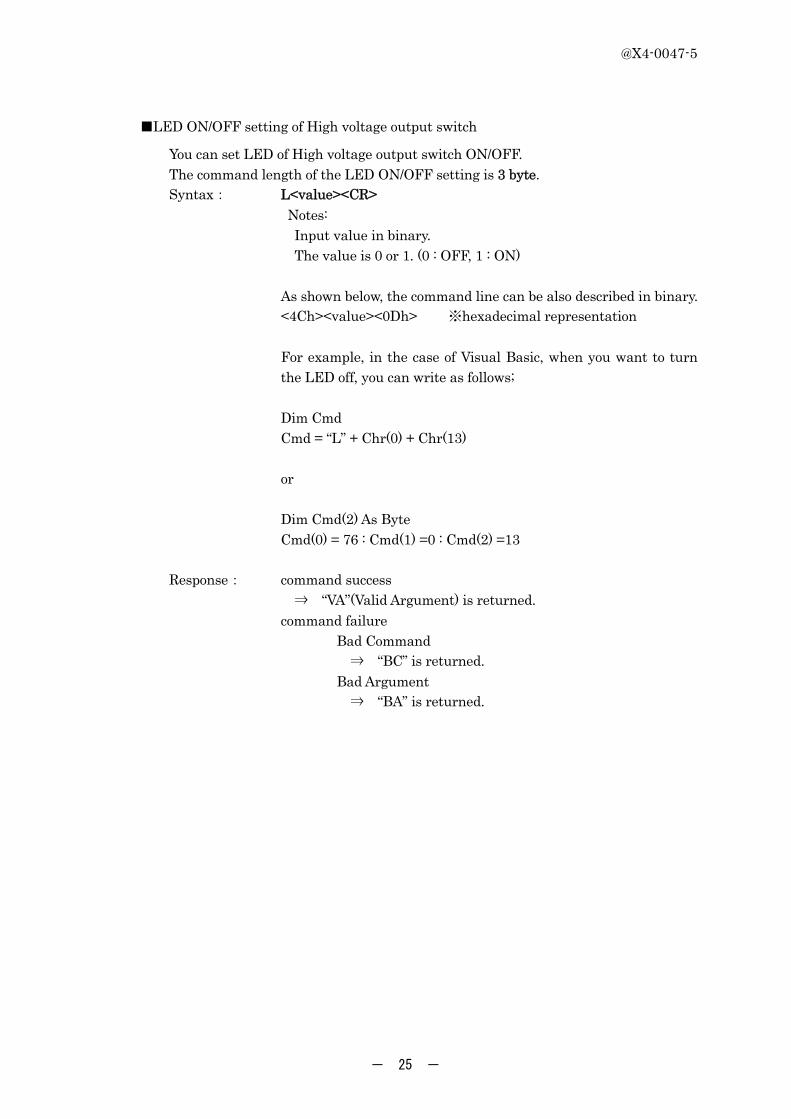
■LED ON/OFF setting of High voltage output switch
You can set LED of High voltage output switch ON/OFF. The command length of the LED ON/OFF setting is 3 byte.
Syntax: L<value><CR> Notes: Input value in binary. The value is 0 or 1. (0 : OFF, 1 : ON) As shown below, the command line can be also described in binary. <4Ch><value><0Dh> ※hexadecimal representation
For example, in the case of Visual Basic, when you want to turn the LED off, you can write as follows; Dim Cmd Cmd = “L” + Chr(0) + Chr(13) or Dim Cmd(2) As Byte Cmd(0) = 76 : Cmd(1) =0 : Cmd(2) =13
Response: command success ⇒ “VA”(Valid Argument) is returned.
command failure Bad Command
⇒ “BC” is returned. Bad Argument
⇒ “BA” is returned.
@X4-0047-5
- 26 -
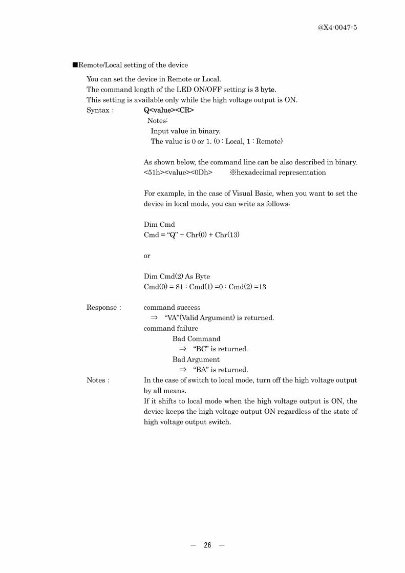
■Remote/Local setting of the device
You can set the device in Remote or Local. The command length of the LED ON/OFF setting is 3 byte. This setting is available only while the high voltage output is ON.
Syntax: Q<value><CR> Notes: Input value in binary. The value is 0 or 1. (0 : Local, 1 : Remote) As shown below, the command line can be also described in binary. <51h><value><0Dh> ※hexadecimal representation
For example, in the case of Visual Basic, when you want to set the device in local mode, you can write as follows; Dim Cmd Cmd = “Q” + Chr(0) + Chr(13) or Dim Cmd(2) As Byte Cmd(0) = 81 : Cmd(1) =0 : Cmd(2) =13
Response: command success ⇒ “VA”(Valid Argument) is returned.
command failure Bad Command
⇒ “BC” is returned. Bad Argument
⇒ “BA” is returned. Notes: In the case of switch to local mode, turn off the high voltage output
by all means. If it shifts to local mode when the high voltage output is ON, the device keeps the high voltage output ON regardless of the state of high voltage output switch.
@X4-0047-5
- 27 -
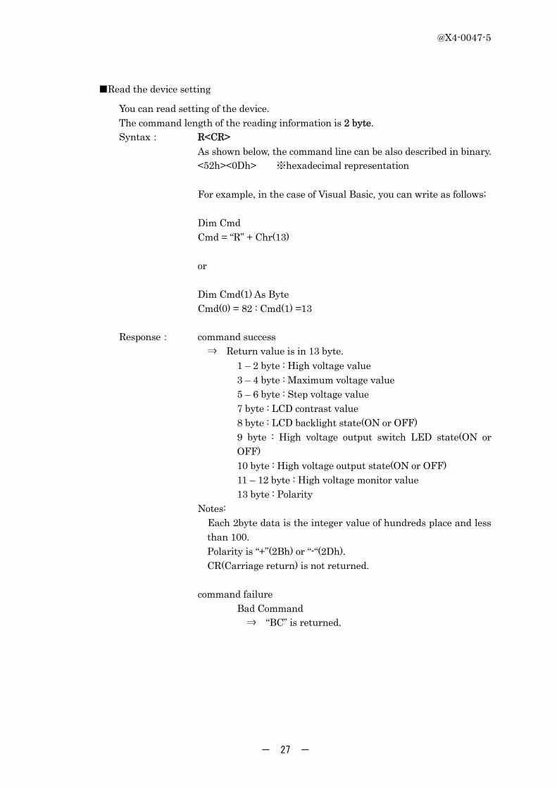
■Read the device setting
You can read setting of the device. The command length of the reading information is 2 byte.
Syntax: R<CR> As shown below, the command line can be also described in binary. <52h><0Dh> ※hexadecimal representation
For example, in the case of Visual Basic, you can write as follows; Dim Cmd Cmd = “R” + Chr(13) or Dim Cmd(1) As Byte Cmd(0) = 82 : Cmd(1) =13
Response: command success ⇒ Return value is in 13 byte. 1 – 2 byte : High voltage value 3 – 4 byte : Maximum voltage value 5 – 6 byte : Step voltage value 7 byte : LCD contrast value 8 byte : LCD backlight state(ON or OFF)
9 byte : High voltage output switch LED state(ON or OFF)
10 byte : High voltage output state(ON or OFF) 11 – 12 byte : High voltage monitor value 13 byte : Polarity Notes:
Each 2byte data is the integer value of hundreds place and less than 100. Polarity is “+”(2Bh) or “-“(2Dh). CR(Carriage return) is not returned.
command failure Bad Command
⇒ “BC” is returned.

@X4-0047-5
- 28 -
■Read high voltage monitor value
You can read the high voltage monitor value. The command length of the high voltage monitor value is 2 byte.
Syntax: T<CR> As shown below, the command line can be also described in binary. <54h><0Dh> ※hexadecimal representation
For example, in the case of Visual Basic, you can write as follows; Dim Cmd Cmd = “T” + Chr(13) or Dim Cmd(1) As Byte Cmd(0) = 84 : Cmd(1) =13
Response: command success ⇒ Return value is in 2 byte. Notes:
Return value is the integer value of the hundreds place and less than 100. CR(Carriage return) is not returned.
command failure Bad Command
⇒ “BC” is returned.

@X4-0047-5
- 29 -
■Read low voltage monitor value
You can read low voltage monitor value. The command length of the low voltage monitor value is 2 byte.
Syntax: A<CR> As shown below, the command line can be also described in binary. <41h><0Dh> ※hexadecimal representation
For example, in the case of Visual Basic, you can write as follows; Dim Cmd Cmd = “A” + Chr(13) or Dim Cmd(1) As Byte Cmd(0) = 65 : Cmd(1) =13
Response: command success ⇒ Return value is in 8 byte. 1 – 2 byte : positive 5V monitor value 3 – 4 byte : negative 5V monitor value 5 – 6 byte : positive 15V monitor value 7 – 8 byte : negative 15V monitor value Notes:
Return value is the integer part and 2 decimal places. 2 decimal places are output as the numerical value of 100 times. CR(Carriage return) is not returned.
command failure Bad Command
⇒ “BC” is returned.

@X4-0047-5
- 30 -
■Reset the device to the condition at power-on.
You can reset the device to the condition at power-on. The command length of the reset is 2 byte.
Syntax: D<CR> As shown below, the command line can be also described in binary. <44h><0Dh> ※hexadecimal representation
For example, in the case of Visual Basic, you can write as follows; Dim Cmd Cmd = “D” + Chr(13) or Dim Cmd(1) As Byte Cmd(0) = 68 : Cmd(1) =13
Response: command success ⇒ “VA”(Valid Argument) is returned.
command failure Bad Command
⇒ “BC” is returned.

@X4-0047-5
- 31 -
■Read information
You can read information of the device. The command length of the reading information is 2 byte.
Syntax: F<CR> As shown below, the command line can be also described in binary. <46h><0Dh> ※hexadecimal representation
For example, in the case of Visual Basic, you can write as follows; Dim Cmd Cmd = “F” + Chr(13) or Dim Cmd(1) As Byte Cmd(0) = 70 : Cmd(1) =13
Response: command success ⇒ Return value is in 24 byte. 1 – 8 byte : Firmware version 9 – 16 byte : Type Name 17 – 24 byte : Serial Number Notes: Return value is a character string.
When the each item is less than 8 characters, it is filed with space characters. CR(Carriage return) is not returned.
command failure Bad Command
⇒ “BC” is returned. Bad Argument
⇒ “BA” is returned.
@X4-0047-5
- 32 -
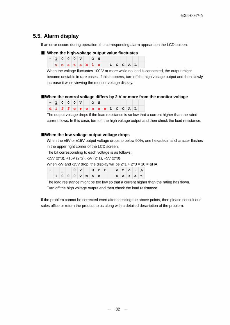
5.5. Alarm display
If an error occurs during operation, the corresponding alarm appears on the LCD screen.
■ When the high-voltage output value fluctuates - 1 0 0 0 V O N
u n s t a b l e L O C A L
When the voltage fluctuates 100 V or more while no load is connected, the output might
become unstable in rare cases. If this happens, turn off the high voltage output and then slowly
increase it while viewing the monitor voltage display.
■When the control voltage differs by 2 V or more from the monitor voltage - 1 0 0 0 V O N
d i f f e r e n c e L O C A L
The output voltage drops if the load resistance is so low that a current higher than the rated
current flows. In this case, turn off the high voltage output and then check the load resistance.
■When the low-voltage output voltage drops When the ±5V or ±15V output voltage drops to below 90%, one hexadecimal character flashes
in the upper right corner of the LCD screen.
The bit corresponding to each voltage is as follows:
-15V (2^3), +15V (2^2), -5V (2^1), +5V (2^0)
When -5V and -15V drop, the display will be 2^1 + 2^3 = 10 = &HA.
- 0 V O F F e t c . A
1 0 0 0 V m a x . R e s e t
The load resistance might be too low so that a current higher than the rating has flown.
Turn off the high voltage output and then check the load resistance.
If the problem cannot be corrected even after checking the above points, then please consult our
sales office or return the product to us along with a detailed description of the problem.

@X4-0047-5
- 33 -
6. Maintenance and Inspection
6.1. Maintenance and inspection
To use this product safely, perform periodic maintenance and inspections as explained below.
Carefully read the precautions described in this manual and comply with the instructions to
ensure safe use.
If a failure is found or suspected in this product, check the contents of section 6.2, "Repair" and
then contact our local sales office. When you return this product back to us for repair, pack it
carefully so that it is will not be damaged during shipping and add a description of the failure.
Please acknowledge that we accept no responsibility for any damage caused during shipping.
If this product gets wet or oil or dust gets inside, the electrical insulation will deteriorate leading to
hazardous situations such as electrical shock or fire. If this product becomes wet or
contaminated with oil or dust, then immediately stop using it and contact our sales office for
repair service.
Cleaning the unit
Gently wipe away dirt on the unit with a soft, dry cloth. Never use chemical solvents such as
benzene, alcohol, acetone, ether, ketone, thinner and gasoline. Using such solvents will cause
deformation or discoloration.
6.2. Repair
If a failure is found in this product, contact us with the specific symptom and a detailed description
of the trouble, as well as the product model number and production lot number. We will make
every effort to repair the product in as short a time as possible. In the following cases however, the
repair might require additional time and extra costs or its repair might even be refused.
1. The product was purchased a long time ago.
2. The maintenance parts used in the product are not in current production.
3. The product was modified or altered
4. The product was severely damaged.
5. Other unavoidable factors

@X4-0047-5
- 34 -
7. Dimensional Outline
UNIT:mm

@X4-0047-5
- 35 -
8. Warranty
This product has been thoroughly tested and checked to meet the required performance specifications
prior to shipment. However, should any failure or malfunction occur, immediately contact our sales
office or sales representative. The warranty applies only to failures found in this product resulting from
defects in the workmanship or materials used in manufacture. This product is warranted for a period of
one year from the date of delivery. The warranty is limited to repair or replacement of the defective
product.
Even if within the warranty period, this warranty shall not apply to failures in cases where the product
has been misused or mishandled due to not following the instructions in this manual, or modified or
was damaged by accidents such as natural or man-made disasters.
REGULATED HIGH-VOLTAGE DC POWER SUPPLY C9525 SERIES
INSTRUCTION MANUAL
Date of issue: Feb. 2014, The fifth edition
Edited and published by: