instruction manual time domain reflectometer … manual time domain reflectometer mtdr1 ......
TRANSCRIPT

AVTMMTDR1-ENG Rev. A
Dec 2006
Instruction Manual Time Domain Reflectometer
MTDR1
Used with HIGH-VOLTAGE EQUIPMENT
Read this entire manual before operating equipment
M Valley Forge Corporate Center 2621 Van Buren Avenue Norristown, PA 19403-2329 U.S.A. 610-676-8500
www.megger.com

Instruction Manual Time Domain Reflectometer
MTDR1

Copyright 2006 Megger. All rights reserved.
The information presented in this manual is believed to be adequate for the intended use of the product. The products described herein should not be used for purposes other than as specified herein. Specifications are subject to change without notice.
WARRANTY
Products supplied by Megger are warranted against defects in material and workmanship for a period of one year following shipment. Our liability is specifically limited to replacing or repairing, at our option, defective equipment. Equipment returned to the factory for repair must be shipped prepaid and insured. This warranty does not include batteries, lamps, or other expendable items, where the original manufacturer's warranty shall apply. We make no other warranty. The warranty is void in the event of abuse (failure to follow recommended operating procedures) or failure by the customer to perform specific routine maintenance as indicated in this manual.
M
Valley Forge Corporate Center 2621 Van Buren Ave Norristown, PA 19403-2329 610-676-8500 (Telephone) 610-676-8610 (Fax) www.megger.com


AVTMMTDR1-ENG Rev A Dec 2006
i
Table of Contents
Upon Receipt of Product .............................................................................................................. 1
MTDR Analyzer................................................................................................................................
Specifications.............................................................................................................................. 3
Top Panel Controls .................................................................................................................... 5
Communications ports............................................................................................................... 5
Home Screen.............................................................................................................................. 6
Home Screen - Mode Options .................................................................................................. 6
Utilities......................................................................................................................................... 7
Test Parameters – Display Header............................................................................................ 8
Trace Viewer Control ................................................................................................................. 9
TDR - Multiple Trace Capture ................................................................................................. 10 Arc Reflection – Test Contro ................................................................................................... 11 Impulse Current (Surge)........................................................................................................... 12 Decay Method.......................................................................................................................... 12
MTDR Lead length Calibration - Left Cursor Offset............................................................... 13
Troubleshooting ....................................................................................................................... 14 COMLink (Version 1.08) ..................................................................................................................
Introduction.............................................................................................................................. 15
Software Installation................................................................................................................. 16
Connecting the PC to the MTDR............................................................................................. 16
COMLink Home Screen ........................................................................................................... 17
Transferring Wave Forms from the MTDR............................................................................. 19
Multiple Waveform viewing .................................................................................................... 21
Print Waveform ........................................................................................................................ 21
Communications functions ..................................................................................................... 21
Setup Serial Port ....................................................................................................................... 22
COM32 ...................................................................................................................................... 22

AVTMMTDR1-ENG Rev A Dec 2006
ii
M

AVTMMTDR1-ENG Rev A Dec 2006
1
Upon Receipt of Product
Prior to operation, check for loosened hardware or damage incurred during transit. If these conditions are found, a safety hazard is likely, DO NOT attempt to operate equipment. Please contact Megger as soon as possible.
MTDR1 Time Domain Reflectometer

M
AVTMMTDR1-ENG Rev A Dec 2006
2
M

AVTMMTDR1-ENG Rev A Dec 2006
3
MTDR Analyzer
Specifications
Operating modes: ARC Reflection, SURGE, voltage Decay and TDR
Ranges: U.S.: 200, 500, 1000, 2000, 5000, 10,000, 20,000, 50,000, 100,000 ft
Metric: 60, 150, 300, 600, 1500, 3000, 6000, 15,000, 30,000 m
Time: 0.2, 0.5, 1, 2, 5, 10, 20, 50, 100 μs
TDR pulse widths: 40, 80, 160, 320, 640 ns, 1, 2, 5, 10 μs
Cursors: Selectable format: feet, meters, μs
Dual, independent cursors with both positions displayed
Differential cursor position displayed
Resolution: 5 ft (1.50 m), depending on range and mode
Horizontal zoom: Selectable via front panel controls
Velocity selectable: 0 to 99%
0 to 983.6 ft/μs
0 to 299.8 m/μs
0 to 491.8 ft/μs (Vp/2)
Inputs: Input 1: channel one acquisition (TDR and ARC)
Input 2: channel two acquisition (SURGE)
TDR pulse amplitude: 10 V nominal, into 50

M
AVTMMTDR1-ENG Rev A Dec 2006
4
Gain: 1, 2, 3, 4, 5, 10, 20, 50, 100
Input impedance: 50 , all inputs
Max. signal input: 250 V peak for transients
Display: Transflective, daylight viewable color LCD
Operating system: Windows® XP Embedded
External interfaces: Dual USB ports
Serial port
Printer support: Hewlett Packard or others printers supporting standard HP- PCL (Printer Control Language)
Memory: Stores up to 200 waveforms internally
Power: Power is 100 to 240V AC 50/60 Hz self configuring for standalone unit, or for integrated unit, the Power is supplied by PFL40
Temperature range: -4 to 122°F (-20 to 50°C) operating
-22 to 158°F (-30 to 70°C) storage
Humidity: <95 percent non-condensing
Dimensions: Integrated into the top panel of PFL40
Weight: Included in PFL40 system
Accessories supplied: software to download and upload traces to and from a PC and to emulate MTDR operation on a PC for trace analysis and viewing

MTDR Analyzer
AVTMMTDR1-ENG Rev A Dec 2006
5
Top Panel Controls
Test Button:
Initiates and Terminates all Tests.
Navigation Keys:
Use Arrow keys to highlight a desired Selection. Use Enter button (in center) to Activate the Selection.
Home Key:
Returns to Home Screen. Press twice to ignore.
Change Area Key:
Allows User to select Active area of the screen. Selected area outlined in blue.
QWERTY Keys: Provides the operator a full QWERTY key board for entering notes and data.
Power Suspend:
Prepares the Instrument for Shutdown. A message will indicate when Input Power can be safely removed.
Help Function:
Provides on screen Help to assist operator.
Function Key:
Displays the options available for any highlighted Selection.
Communications ports
USB Ports: USB Connectors; For printer cable and USB memory stick.
SERIAL Port Nine-pin Serial COMMs Connector; For PC interface.

M
AVTMMTDR1-ENG Rev A Dec 2006
6
Home Screen
Home Screen - Mode Options
Select for ARC Reflection Mode
Select for TDR Mode
Select for Current Impulse Mode (Surge)
Select for Voltage Decay Mode (optional)
Select to input Preferences
Select to enter File Manager
MTDR Analyzer
AVTMMTDR1-ENG Rev A Dec 2006
7
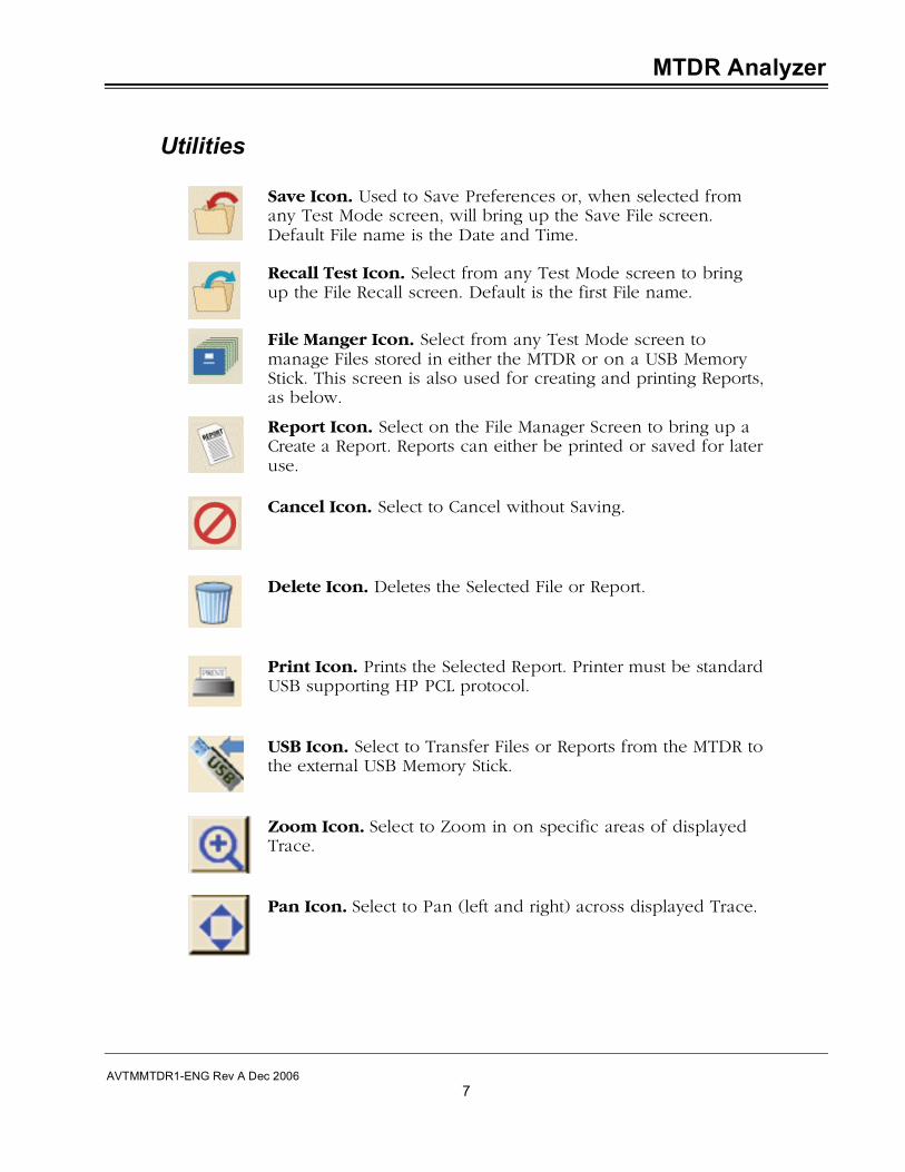
Utilities
Save Icon. Used to Save Preferences or, when selected from any Test Mode screen, will bring up the Save File screen. Default File name is the Date and Time.
Recall Test Icon. Select from any Test Mode screen to bring up the File Recall screen. Default is the first File name.
File Manger Icon. Select from any Test Mode screen to manage Files stored in either the MTDR or on a USB Memory Stick. This screen is also used for creating and printing Reports, as below.
Report Icon. Select on the File Manager Screen to bring up a Create a Report. Reports can either be printed or saved for later use.
Cancel Icon. Select to Cancel without Saving.
Delete Icon. Deletes the Selected File or Report.
Print Icon. Prints the Selected Report. Printer must be standard USB supporting HP PCL protocol.
USB Icon. Select to Transfer Files or Reports from the MTDR to the external USB Memory Stick.
Zoom Icon. Select to Zoom in on specific areas of displayed Trace.
Pan Icon. Select to Pan (left and right) across displayed Trace.

M
AVTMMTDR1-ENG Rev A Dec 2006
8
Test Parameters – Display Header
Indicates selected Test Mode. Arc Reflection Test Mode shown here.
Indicates Cable Length which is set during the TDR mode with automatic placement of the cursors.
Indicates Display Range (as shown on screen). This Display Range can be changed by User.
Indicates Distance between cursors.
Indicates Velocity of Propagation. The velocity normally comes from the Cable Type selected, but can be changed by User.
Indicates Cable Type. Default type is that selected in the Preferences screen.
Indicates Pulse Width which is automatically set based on range. This Width can be changed by User.
Indicates Pulse Amplitude which is automatically set based on range. This Amplitude can be changed by User.
Indicates Testing Status: Stopped, Continuous Sampling, or Armed.
MTDR Analyzer
AVTMMTDR1-ENG Rev A Dec 2006
9
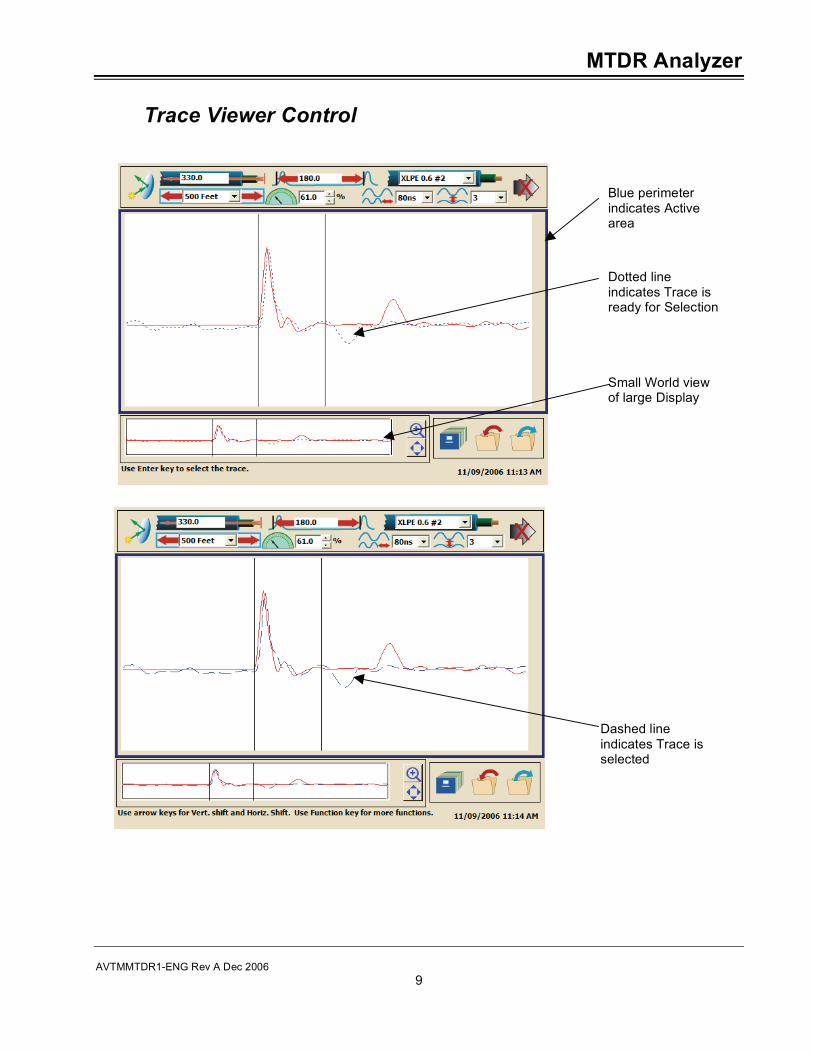
Trace Viewer Control
Blue perimeter indicates Active area
Dotted line indicates Trace is ready for Selection
Small World view of large Display
Dashed line indicates Trace is selected

M
AVTMMTDR1-ENG Rev A Dec 2006
10
TDR - Multiple Trace Capture
Baseline Trace with Cable End open
Second Trace with Cable End shorted
Baseline Trace to automatically identify the start of the Test Lead. Note: If the Cable length is known, then Velocity can be verified. Place the right cursor at the Cable end and begin adjusting the Velocity. When the Distance shown for the right cursor matches the known Cable length, the velocity is set to its correct value.
MTDR Analyzer
AVTMMTDR1-ENG Rev A Dec 2006
11
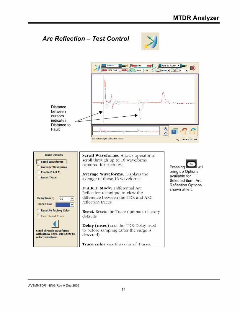
Arc Reflection – Test Control
Scroll Waveforms. Allows operator to scroll through up to 16 waveforms captured for each test. Average Waveforms. Displays the average of those 16 waveforms. D.A.R.T. Mode: Differential Arc Reflection technique to view the difference between the TDR and ARC reflection traces Reset. Resets the Trace options to factory defaults Delay (msec) sets the TDR Delay used to before sampling (after the surge is detected). Trace color sets the color of Traces.
Pressing will bring up Options available for Selected item. Arc Reflection Options shown at left.
Distance between cursors indicates Distance to Fault
M
AVTMMTDR1-ENG Rev A Dec 2006
12
Impulse Current (Surge)
The Impulse Current method is usually an effective method for pre-locating a high-resistance fault (arc resistance greater than 200 ohms). The Impulse Current method is similar to the Arc Reflection method in that both methods send high energy pulses down the cable which are used to break down the fault. The difference is that the Arc Reflection method observes the voltage waves caused by the reflection of the MTDR pulses from the arc at the fault. The Impulse Current method observes the current waves that are caused by the injection of the PFL pulse and its subsequent reflection from the fault. .
When using the Impulse Current method, a current coupler is switched into the surge return circuit and is used to measure the high frequencies in the transient as a series of spikes each separated by the round-trip travel time from the fault back to the PFL.
In general, the left and right cursors are positioned on the peaks of two consecutive reflections from the fault. The first one or two impulses in the transient are due to the outgoing Current Impulse used to energize the cable and may not be related to the fault location. Therefore, the third and later pulses should be used to locate the fault.
Decay Method
Use of the Decay method of fault locating is normally used when the voltage required to sustain an arc at the fault exceeds the normal Surge capability of the PFL system. In this case, a dc dielectric test set is used to charge the cable under test, through a high-impedance Decay Coupler, to a voltage that should cause a breakdown at the fault location. The PFL is able to put out up to 40kV in Decay mode.
The capacitive charge build up on the cable, eventually causes the fault to break down, and a traveling wave is then launched back toward the Decay Coupler in the PFL and is reflected back to the fault (in reverse polarity) where it will be reflected again, until the energy fully dissipates. This reversal of polarity creates the condition such that the Distance to Fault (as measured between the two cursors on the MTDR) will be between a strong peak and an adjacent valley (half-period point).

MTDR Analyzer
AVTMMTDR1-ENG Rev A Dec 2006
13
MTDR Lead length Calibration - Left Cursor Offset
1. With the test leads in place and open, use the TDR mode to
capture a trace. Left cursor will be automatically placed at the start of the outgoing Pulse (left side of first blip).
2. Select and freeze the first Trace. Then, select the second Trace while also temporarily shorting the end of the test leads. The point at which the first and second Traces begin to diverge represents the end of the test leads. Select and freeze the second trace and then move the left cursor to this point of divergence. This change in position (of the left cursor) is referred to as the Left Cursor Offset.
3. To save this offset, use the function select, and check the save offset. This offset will be saved, and will continue to be used until reset.
Spacing equals MTDR Lead length
Point of divergence
M
AVTMMTDR1-ENG Rev A Dec 2006
14
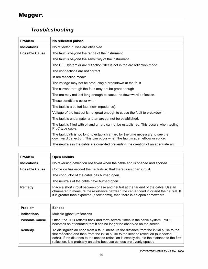
Troubleshooting
Problem No reflected pulses
Indications No reflected pulses are observed
Possible Cause The fault is beyond the range of the instrument
The fault is beyond the sensitivity of the instrument.
The CFL system or arc reflection filter is not in the arc reflection mode.
The connections are not correct.
In arc reflection mode:
The voltage may not be producing a breakdown at the fault
The current through the fault may not be great enough
The arc may not last long enough to cause the downward deflection.
These conditions occur when
The fault is a bolted fault (low impedance).
Voltage of the test set is not great enough to cause the fault to breakdown.
The fault is underwater and an arc cannot be established.
The fault is filled with oil and an arc cannot be established. This occurs when testing PILC type cable.
The fault path is too long to establish an arc for the time necessary to see the downward deflection. This can occur when the fault is at an elbow or splice.
The neutrals in the cable are corroded preventing the creation of an adequate arc.
Problem Open circuits
Indications No reversing deflection observed when the cable end is opened and shorted
Possible Cause Corrosion has eroded the neutrals so that there is an open circuit.
The conductor of the cable has burned open.
The neutrals of the cable have burned open.
Remedy Place a short circuit between phase and neutral at the far end of the cable. Use an ohmmeter to measure the resistance between the center conductor and the neutral. If it is greater than expected (a few ohms), than there is an open somewhere.
Problem Echoes
Indications Multiple (ghost) reflections
Possible Cause Often, the TDR reflects back and forth several times in the cable system until it becomes so attenuated that it can no longer be observed on the screen
Remedy To distinguish an echo from a fault, measure the distance from the initial pulse to the first reflection and then from the initial pulse to the second reflection (suspected echo). If the distance to the second reflection is exactly double the distance to the first reflection, it is probably an echo because echoes are evenly spaced.

AVTMMTDR1-ENG Rev A Dec 2006
15
COMLink (Version 1.08)
Introduction
COMLink is Megger's software program for use with your MTDR Analyzer.
COMLink allows the bi-directional transfer of test data (waveforms) between the MTDR and a Personal Computer (PC).
COMLink software consists of two programs—COMLink, which provides the interface to the MTDR, and COM32, which provides the communication to the MTDR. COMLink takes care of starting and terminating COM32. Your COMLink installation CD will install both COMLink and COM32.
Data is transferred vie either a USB memory stick or through an RS232 serial cable, which connects the MTDR to the PC. If using the serial cable, the MTDR and the PC must operate with the same communication parameters.
System Requirements for PC
Operating system: Windows NT 3.1 or later; Windows 95 or later
Processor: 80386 or higher
Monitor resolution: VGA or higher
Display properties: 600 x 800 and small fonts
RAM: 16 M
Communications port:
9600 baud or better
Storage USB stick, 3½-inch inch floppy disk drive, or CD-ROM

M
AVTMMTDR1-ENG Rev A Dec 2006
16
Software Installation
NOTE: COMLink uses DART/MTDR interchangeably.
To install COMLink, load the COMLink CD into your CD-ROM drive and follow the on-screen instructions.
Figure C-1. COMLink Installation screen
Connecting the PC to the MTDR
You may power up the MTDR before or after connection to the PC, however be sure the MTDR is properly and securely connected to the PC (via RS232 serial cable) before starting COMLink. Refer to Addendum A for the location of the RS232 serial port.
1. Access the COMLink program by clicking on Start.
2. From the Programs menu, select COMLink and then, from the submenu, COMLink.
3. COMLink automatically sets the communication parameters at 19200 baud, 8 data bits, 1 stop bit and no parity. The MTDR uses 19200 band for communication.

COMLink
AVTMMTDR1-ENG Rev A Dec 2006
17
COMLink Home Screen
When opening the COMLink program, the Home Screen is displayed. From the Select Device drop down menu, select the DART (MTDR) device.
Figure C-2. COMLink Home Screen
Select Device
After selecting DART (MTDR) as the remote device, the COMLink program initially displays the Login tab. Login ID and Password are not required to use COMLink with the MTDR Analyzer. Next, click on Login.
Figure C-3. Successful Connection Confirmation Screen
M
AVTMMTDR1-ENG Rev A Dec 2006
18
If your login is successful, the screen will display the Catalog number 654000, the MTDR Serial Number, and software version. Also, the name of the Login tab will change to Logout. If your login is unsuccessful, the Remote Device button will remain disabled.
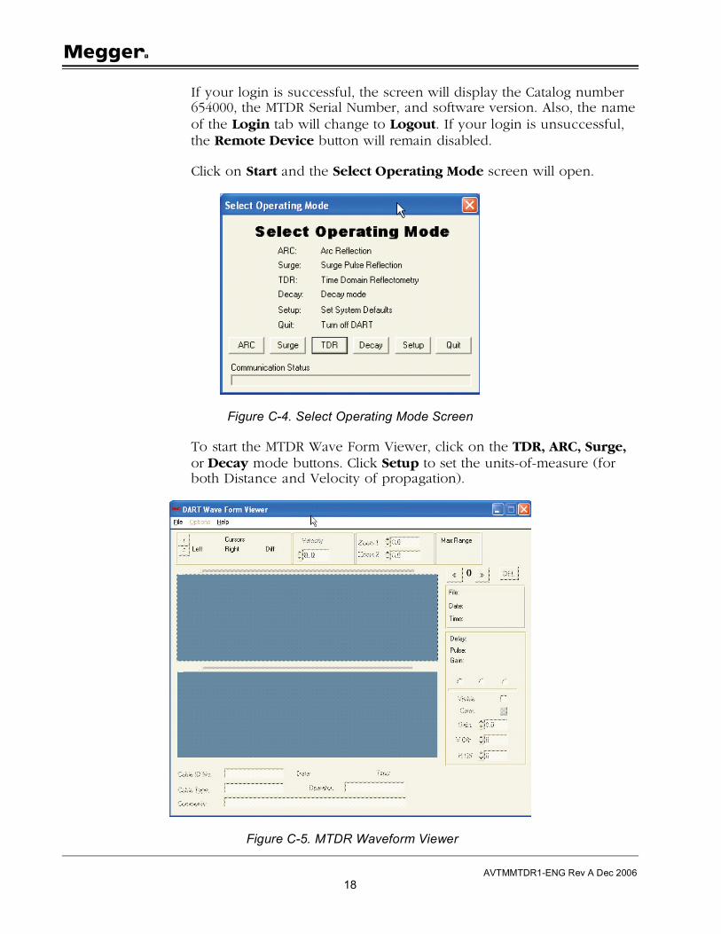
Click on Start and the Select Operating Mode screen will open.
Figure C-4. Select Operating Mode Screen
To start the MTDR Wave Form Viewer, click on the TDR, ARC, Surge, or Decay mode buttons. Click Setup to set the units-of-measure (for both Distance and Velocity of propagation).
Figure C-5. MTDR Waveform Viewer
COMLink
AVTMMTDR1-ENG Rev A Dec 2006
19
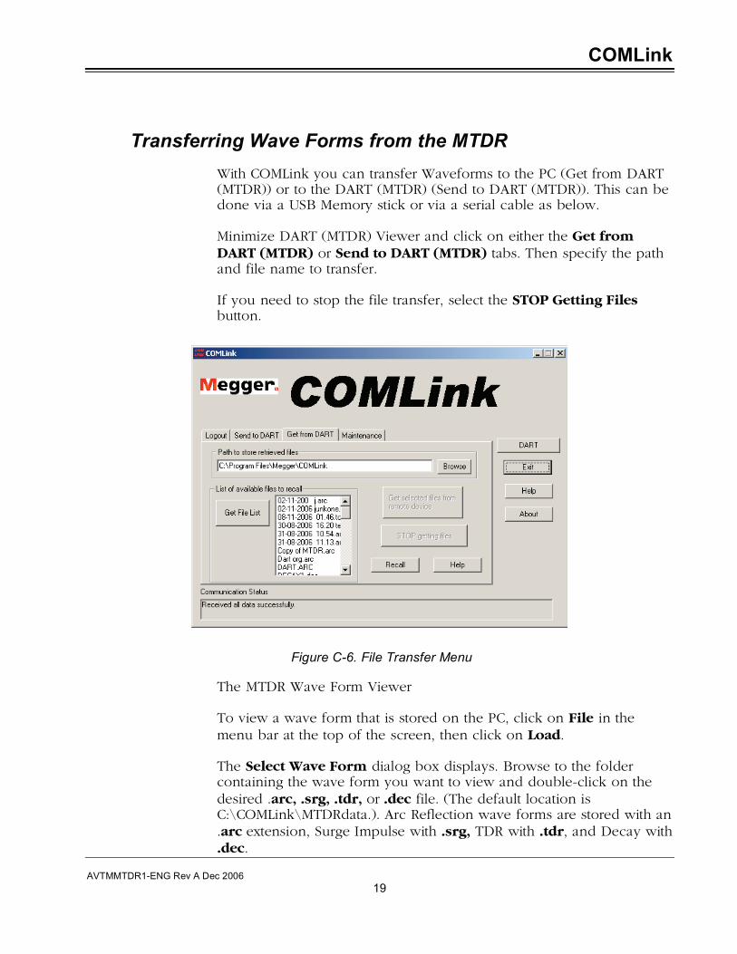
Transferring Wave Forms from the MTDR
With COMLink you can transfer Waveforms to the PC (Get from DART (MTDR)) or to the DART (MTDR) (Send to DART (MTDR)). This can be done via a USB Memory stick or via a serial cable as below.
Minimize DART (MTDR) Viewer and click on either the Get from DART (MTDR) or Send to DART (MTDR) tabs. Then specify the path and file name to transfer.
If you need to stop the file transfer, select the STOP Getting Files button.
Figure C-6. File Transfer Menu
The MTDR Wave Form Viewer
To view a wave form that is stored on the PC, click on File in the menu bar at the top of the screen, then click on Load.
The Select Wave Form dialog box displays. Browse to the folder containing the wave form you want to view and double-click on the desired .arc, .srg, .tdr, or .dec file. (The default location is C:\COMLink\MTDRdata.). Arc Reflection wave forms are stored with an .arc extension, Surge Impulse with .srg, TDR with .tdr, and Decay with .dec.
M
AVTMMTDR1-ENG Rev A Dec 2006
20
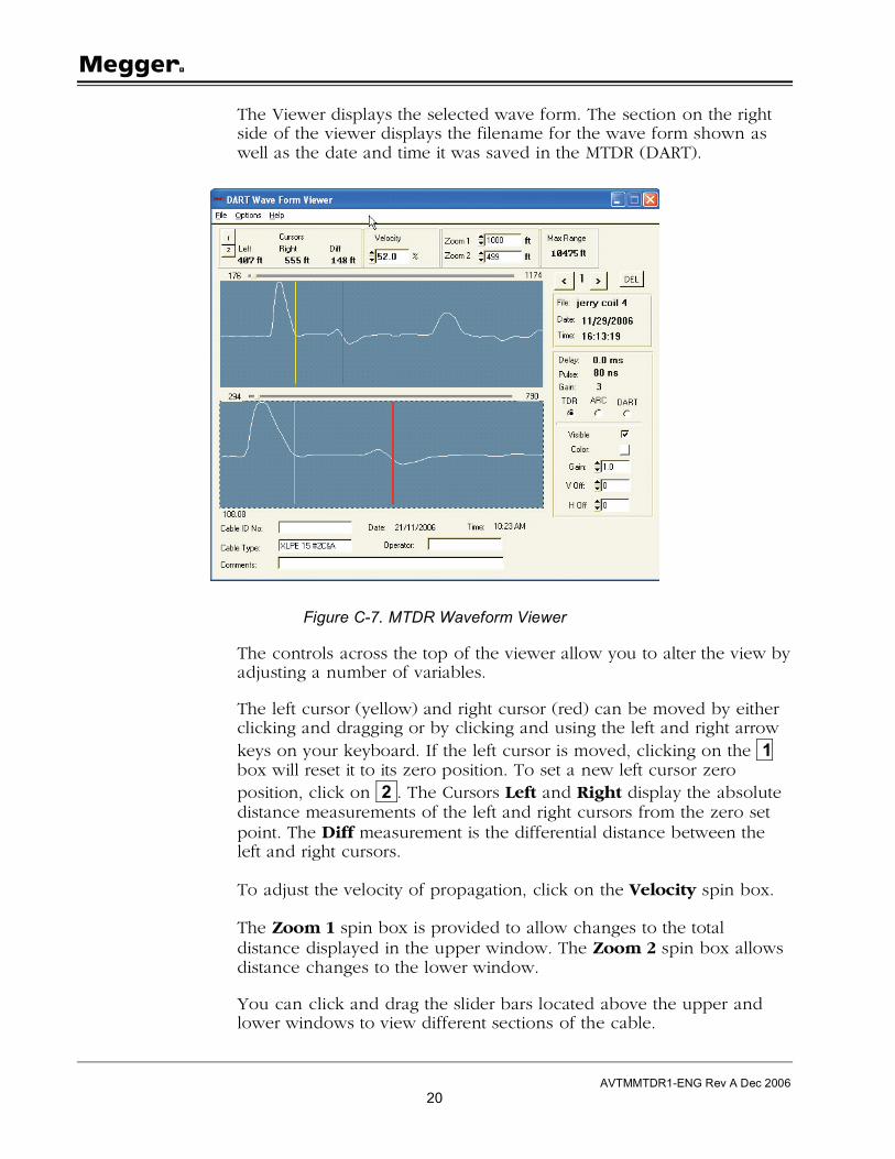
The Viewer displays the selected wave form. The section on the right side of the viewer displays the filename for the wave form shown as well as the date and time it was saved in the MTDR (DART).
Figure C-7. MTDR Waveform Viewer
The controls across the top of the viewer allow you to alter the view by adjusting a number of variables.
The left cursor (yellow) and right cursor (red) can be moved by either clicking and dragging or by clicking and using the left and right arrow keys on your keyboard. If the left cursor is moved, clicking on the 1 box will reset it to its zero position. To set a new left cursor zero position, click on 2 . The Cursors Left and Right display the absolute distance measurements of the left and right cursors from the zero set point. The Diff measurement is the differential distance between the left and right cursors.
To adjust the velocity of propagation, click on the Velocity spin box.
The Zoom 1 spin box is provided to allow changes to the total distance displayed in the upper window. The Zoom 2 spin box allows distance changes to the lower window.
You can click and drag the slider bars located above the upper and lower windows to view different sections of the cable.

COMLink
AVTMMTDR1-ENG Rev A Dec 2006
21
You may also view the TDR, ARC or DART (MTDR) traces, if available, for the wave form, individually or all at once. Click on the Options tab for the desired method, and then click the Visible checkbox to display the trace.
Figure C-8. MTDR Waveform Viewer – Control Box
The Gain and Offsets of the individual TDR, ARC or DART (MTDR) traces can be altered by selecting a value in the spin box. A color pallet is also provided to color the various displayed traces.
Multiple Waveform viewing
Up to three files can be loaded into the Viewer at one time. If the Velocity used was identical for all three traces, the arrows above the file name toggle through each of the three traces and display the appropriate file name, date, time, pulse width and gain for each trace.
Click on DEL only if you want to discard the wave form from the Viewer. Note: this will not delete the file from its saved location.
Print Waveform
To print the Waveform display, click on File and then Print and follow the on-screen instructions.
Communications functions
The MTDR and the COMLink software must always operate with the same communications parameters. If you find it necessary to change
Click here to select method
Click here to display/hide trace Click a spin
box to alter Gain or differentials

M
AVTMMTDR1-ENG Rev A Dec 2006
22
the communications parameters for COMLink, you can do so from the Maintenance tab.
Click on Maintenance to display the Maintenance tab, and then select DART (MTDR) from the Select Device drop-down list.
Figure C-9. Serial Port Set Screen
Setup Serial Port
When necessary, use this feature to adjust the communications parameters.
Click on Setup Serial Port. Select either COM1 or COM2.
To save the new settings and initialize the serial port, click Save Settings.
To Exit without saving, click the Restore Settings button.
COM32
COM32 provides the communication to the remote device. COMLink takes care of starting and terminating COM32. If you need to view the communication status, click on START, PROGRAMS, COMLink, COM32. The resulting window shows all commands and responses to commands going between COMLink, COM32 and the remote device. The following abbreviations indicate where the commands and responses are coming from:

COMLink
AVTMMTDR1-ENG Rev A Dec 2006
23
RI: Response to command came from the remote device
RO: Command was sent to the remote device
CO: Response to a command was sent to the client (COMLink)
Other items in the window, which are generated by COM32, may or may not be preceded by one of the above indicators.