instruction manual three phase mechanical autolink
TRANSCRIPT

1YSA160003-EN - Rev. 5 Instruction Manual
Three Phase Mechanical AutoLink Three Phase Mechanical Electronic Sectionalizer
15kV / 27kV
125kV / 150kV
1YSA160003-EN - Rev. 5 2 / 19
Table of Contents
Section A: Safety Notices ......................................................................................................... 3
Section B: Introduction ............................................................................................................ 4
B.1. About this Document ........................................................................................................................... 4
B.2. Target Group ....................................................................................................................................... 4
B.3. Related Documentation ....................................................................................................................... 4
Section C: Operation of the AutoLink ..................................................................................... 5
C.1. General ................................................................................................................................................ 5
C.2. Operating Under Fault Conditions ..................................................................................................... 5
C.2.1. Operating Under Temporary Fault Conditions .................................................................................. 5
C.2.2. Operating Under Permanent Fault Conditions .................................................................................. 6
C.3. Minimum Time Required for Power up the AutoLink ......................................................................... 6
C.4. Minimum Autoreclosing Operating Time required for AutoLink operation ....................................... 7
Section D: Preparing for Use ................................................................................................... 8
D.1. Packing and Transportation ............................................................................................................... 8
D.2. Checking on Reception ........................................................................................................................ 8
D.3. Storage ................................................................................................................................................ 8
D.4. Installation .......................................................................................................................................... 9
D.4.1. General ................................................................................................................................................ 9
D.4.2. Installation and Service Conditions .................................................................................................... 9
D.4.3. AutoLink setup ..................................................................................................................................... 9
D.4.3.1. Component parts of Each AutoLink ............................................................................................. 9
D.4.3.2. Opening of the Unit .................................................................................................................... 10
D.4.3.3. Dip-Switch Configuration .......................................................................................................... 10
D.4.3.4. Closing of the Unit ..................................................................................................................... 11
D.4.3.5. AutoLink Repositioning .............................................................................................................. 12
D.4.3.6. Lifting the Device ....................................................................................................................... 14
D.4.3.7. Pole fixture ................................................................................................................................. 14
D.4.3.8. Mounting the AutoLinks in the three phase body ....................................................................... 16
D.5. Commissioning .................................................................................................................................. 17
D.5.1. General procedures ........................................................................................................................... 17
Section E: Maintenance ......................................................................................................... 18

1YSA160003-EN - Rev. 5 3 / 19
Section A: Safety Notices
Do not perform any of the activities described on this document with any Sectionalizer energized.
All the activities listed on this document it must be performed with all Sectionalizers completely de-energized and out of service.
ALWAYS follow your company Safety procedures before performing any work on this equipment.
This product is intended to be operated and maintained by qualified persons, thoroughly trained and knowledgeable of hazards
involved. This document is written only for such qualified persons and is not intended to be a substitute for adequate training and experience
in safety procedures for this device.
Detailed descriptions of procedures, safety principles and service operations are not included on this document.
These warnings do not cover all conceivable ways in which service, whether or not recommended by ABB, might be performed
or the possible hazardous consequences of each conceivable way, nor could ABB investigate such ways. Anyone using service procedures
or tools, whether or not recommended by ABB, must satisfy himself thoroughly that neither personal safety nor equipment safety will be
jeopardized by the service method or tools selected.
For Your Safety!
Make sure that the installation area (spaces, divisions and ambient) is suitable for electrical apparatus.
Check that all the installation, putting into service and maintenance operations are carried out by personnel with suitable
knowledge of the apparatus.
Make sure that the standard and legal prescriptions are complied with during installation, putting into service and
maintenance, so that installations according to the rules of good working practice and safety in the workplace are constructed.
Strictly follow the information given in this document.
Check that the rated performance of the apparatus is not exceeded during service.
Check that the personnel operating the apparatus have this document at hand, as well as all necessary information for correct
intervention.
Pay special attention to the danger notes indicated in this document by the following symbol:
Responsible behavior safeguards your own and other’s safety!
For any requests, please contact ABB. The information and illustrations are not binding. We reserve the right to make changes during technical development of the product.
HAZARDOUS VOLTAGE
CAN SHOCK, BURN
OR CAUSE DEATH

1YSA160003-EN - Rev. 5 4 / 19
Section B: Introduction
B.1. About this Document
This document contains the required information to install medium voltage Three Phase Mechanical AutoLink and put it into
service.
For a correct use of the product, please read it carefully.
Like every apparatus we manufacture, Three Phase Mechanical AutoLink is designed for specific applications.
Use only original spare parts.
For further information, please read the technical catalogue.
This user manual is written according the standard IEC 82079-1.
READ CAREFULLY THIS DOCUMENT BEFORE USE.
KEEP FOR FUTURE REFERENCE.
B.2. Target Group
This document is written only for such qualified persons, thoroughly trained and knowledgeable of hazards involved.
B.3. Related Documentation
This document and product-related documentation can be downloaded from the website of ABB: http://www.abb.com
1YSA160003-EN - Rev. 5 5 / 19
Section C: Operation of the AutoLink
C.1. General
The AutoLink Electronic Sectionalizer is a protection device that operates at a permanent fault in the distribution line. It must be
used together with an upstream recloser or circuit breaker with reclosure capability. Please take note that the AutoLink is not a fuse tripping
device, therefore it cannot be used as a protection device by itself.
The main function of the AutoLink is to discriminate between permanent and transient faults in the distribution line, making it
possible for the upstream recloser or substation breaker to clear transient faults without permanent interruption to the customers.
The AutoLink is not a fuse tripping device, it will operate to isolate a permanent fault on no load condition. The AutoLink fits into
a standard fuse cutout and it directly replaces an existing fuse base. When it operates the AutoLink drops open like a fuse.
The AutoLink Electronic Sectionalizer is designed ONLY to protect electrical
equipment and NOT for saving people from accidents or electrocution when
contacting energized circuits.
C.2. Operating Under Fault Conditions
C.2.1. Operating Under Temporary Fault Conditions
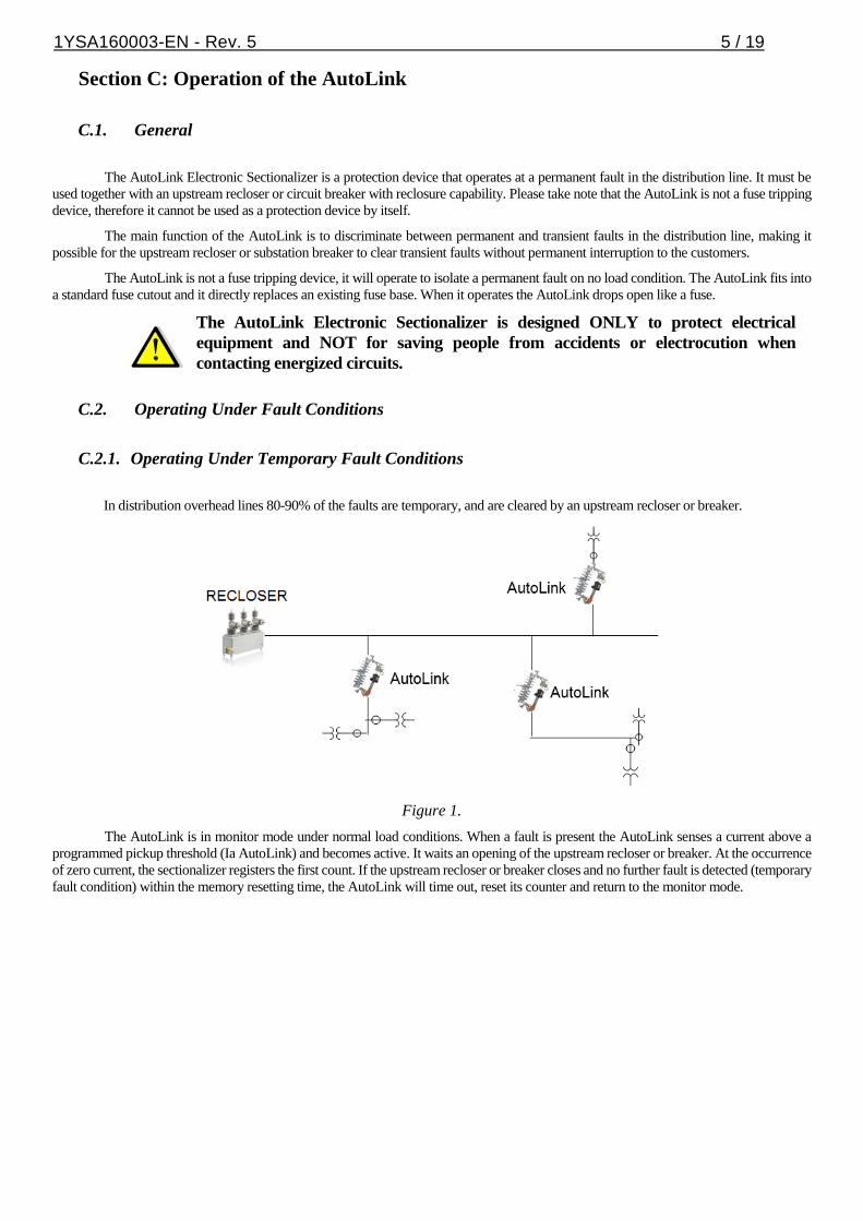
In distribution overhead lines 80-90% of the faults are temporary, and are cleared by an upstream recloser or breaker.
Figure 1.
The AutoLink is in monitor mode under normal load conditions. When a fault is present the AutoLink senses a current above a
programmed pickup threshold (Ia AutoLink) and becomes active. It waits an opening of the upstream recloser or breaker. At the occurrence
of zero current, the sectionalizer registers the first count. If the upstream recloser or breaker closes and no further fault is detected (temporary
fault condition) within the memory resetting time, the AutoLink will time out, reset its counter and return to the monitor mode.

1YSA160003-EN - Rev. 5 6 / 19
Figure 2.
C.2.2. Operating Under Permanent Fault Conditions
The remaining 10-20% of faults in distribution overhead lines are considered permanent. During these faults, the continuous cycling
of the recloser does not clear the fault. .The AutoLink will pickup, measure zero current and count, reaching its trip count setting.
The AutoLink will trip on the last open cycle of the recloser, isolating the permanent fault in its branch and allowing the recloser
to close prior to going to lockout and maintain power to the unaffected branches.
Figure 3.
The times shown in Diagrams B and C as T1 correspond to the time the recloser takes to reconnect the circuit. This “dead time” is
usually adjustable up to 3 minutes. The AutoLink can operate while keeping the count performed with the current at zero for up to
3.5 minutes, above any possible dead line value configured in the recloser.
Due to the latest technological improvements recently introduced to reclosers, the time indicated as T2 is the time the recloser takes
to open after the fault is detected. The AutoLink, by means of the spectral analysis in the second harmonic, only needs one cycle
to identify a current as a fault current, isolating it from symmetric and asymmetric inrush currents. This feature adds an outstanding
technical advantage to the AutoLink.
C.3. Minimum Time Required for Power up the AutoLink
The AutoLink is a self-powered device. The following graphs displays the minimum time required for the device to be powered at
different currents to enable the operation. The AutoLink can harvest the required energy from the precharge current and also from the fault
current as far as it fulfills the time-current requirement for fully charge its main energy storage device. The minimum nominal current of
the AutoLink to be fully charged is 5A.

1YSA160003-EN - Rev. 5 7 / 19
Figure 4.
C.4. Minimum Autoreclosing Operating Time required for AutoLink operation
The AutoLink requires a line current greater than 5 A in order to be fully charged during at least 15 seconds. After the condition of
the device is fully charged the line current can vary as low as 3A and it will continue to be operative.
The recloser should set its reclaim time to 15 seconds in order to prevent an auto-reclosing sequence before the AutoLink is fully
charged. If a fault happens before that timer, the recloser goes directly to lockout preventing the recloser cycle operation.
The AutoLink is able to detect a fault on the line with a period as small as one cycle. So the recloser can be set to start the tripping
command as long as it enables to flow through the sectionalizer one sinusoidal cycle in order to correctly measure the fault using its detection
algorithm.
The minimum opening time that the recloser is set to maintain the line deenergized after a fault during a reclosing cycle must be
set higher than 0,5 seconds in order to permit the AutoLink to perform the mechanical trip and safely isolate its connected faulty load and
isolate the fault from the other branches connected to the recloser.
Figure 5.
0
1
2
3
4
5
6
7
8
9
10
0 20 40 60 80 100 120
Tim
e [s
]
Current [A]
Minimum Current - Time Requirement

1YSA160003-EN - Rev. 5 8 / 19
Section D: Preparing for Use
All installation, putting into service, commissioning and maintenance operations
must be carried out by suitably qualified personnel with in-depth knowledge of
the apparatus.
D.1. Packing and Transportation
Packing contains one three phase porcelain body and three AutoLink electronic sectionalizers.
Packing cage is made of wood. Three phase porcelain body is fixed to the pallet by means of specific brackets and AutoLink
electronic sectionalizers are shipped in cardboard package, in armed position, fixed to the pallet as well.
D.2. Checking on Reception
Before carrying out any operation, always make sure that the operating mechanism
springs are charged and that the apparatus is in armed position. When performing a
reception test, it is required to wait 5 minutes with the device de-energized after a
tripping operation, to reset it.
On reception, check the state of the apparatus, integrity of the packing and nameplate information is the same requested on the
purchase order specifications.
Make sure that all materials described in the shipping note are included in the supply.
If any damage or irregularity is seen in the supplied product after unboxing, notify ABB (directly or through the agent or distributor)
as soon as possible within five days of receipt. Please inquire about the terms of warranty from your nearest ABB representative.
The apparatus is only supplied with the accessories specified at the time of ordering and validated in the order acknowledgement
sent by ABB.
The documents sent in the shipping packing are:
- User Manual (this document).
- User Manual for each AutoLink.
- Test Certification.
- Product Warranty.
- Packing List.
Other documents which are sent prior to shipment of the apparatus are:
- Order acknowledgement.
- Original shipping advice notes.
- Any drawings or documents referring to special configurations/conditions.
D.3. Storage
When the apparatus is unboxed, it must be carefully unpacked and checked as described in Section C.2. of this manual.
If immediate installation is not possible, store the equipment on its original packaging in a covered, well-ventilated, dry, dust-free,
non-corrosive ambient, away from any flammable materials and at a temperature between -5°C and +45°C.
In any case, avoid any accidental impacts or positioning which stresses the apparatus.
1YSA160003-EN - Rev. 5 9 / 19
D.4. Installation
D.4.1. General
Correct installation is very important. The manufacturer’s instructions must be
carefully studied and followed. It is good practice to use gloves for handling the pieces
during installation.
D.4.2. Installation and Service Conditions
The following standards must be taken into particular consideration during installation and service:
- IEC 60694.
- IEC 61936: Electrical Installation.
- ANSI C37 63: Automatic Sectionalizer.
- All accident prevention regulations in relative countries.
The AutoLink is compatible with the Fuses bases model ICX from ABB, Type XS from SYC, Type C from AB Chance and Type
L from Cooper.
For special installation requirements or other operating conditions, please contact ABB.
D.4.3. AutoLink setup
The following setting procedure for the actuating current, count parameters and mechanical arm actuator must be performed
according to the User Manual document for the AutoLink Electronic Sectionalizer and is explained bellow.
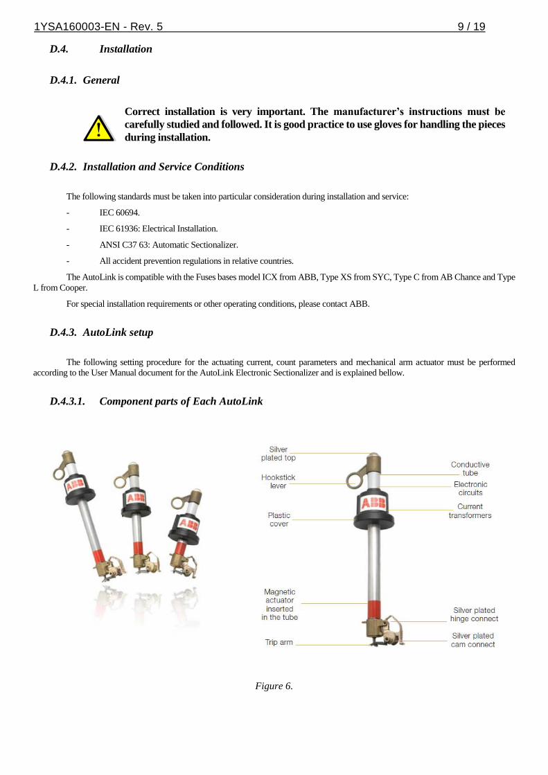
D.4.3.1. Component parts of Each AutoLink
Figure 6.
1YSA160003-EN - Rev. 5 10 / 19
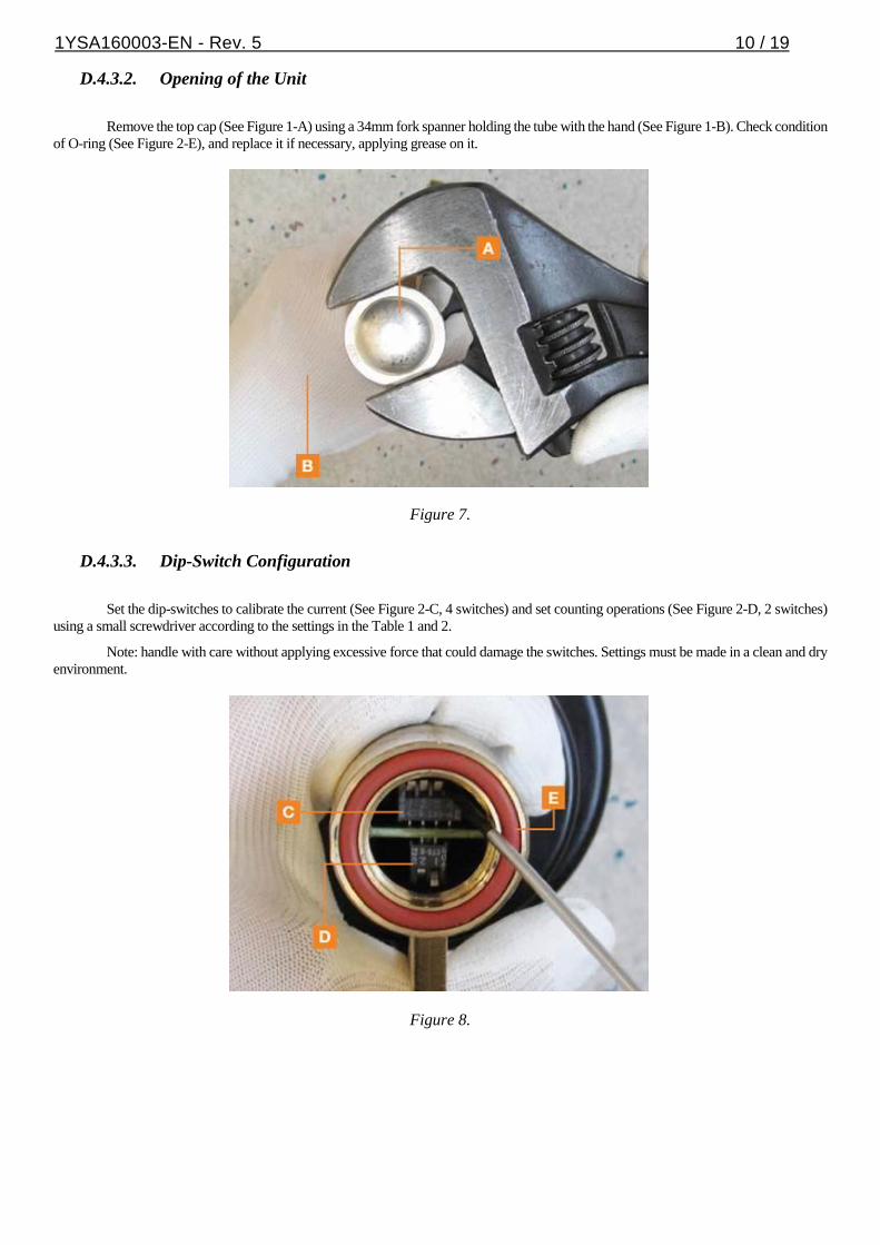
D.4.3.2. Opening of the Unit
Remove the top cap (See Figure 1-A) using a 34mm fork spanner holding the tube with the hand (See Figure 1-B). Check condition
of O-ring (See Figure 2-E), and replace it if necessary, applying grease on it.
Figure 7.
D.4.3.3. Dip-Switch Configuration
Set the dip-switches to calibrate the current (See Figure 2-C, 4 switches) and set counting operations (See Figure 2-D, 2 switches)
using a small screwdriver according to the settings in the Table 1 and 2.
Note: handle with care without applying excessive force that could damage the switches. Settings must be made in a clean and dry
environment.
Figure 8.

1YSA160003-EN - Rev. 5 11 / 19
Table 1 and 2.
D.4.3.4. Closing of the Unit
Once the calibration current and counts are set, cover the dip-switch with silicon grease (See Figure 3), supplied with AutoLink.
Figure 9.
Check the condition of the O-Ring (See Figure 2-E) and apply silicon grease (See Figure 4-F) both inside the cap and over the dip-
switches.

1YSA160003-EN - Rev. 5 12 / 19
Figure 10.
Place the cap, holding the tube with the hand, and tighten it using a 34 mm fork spanner (torque between 8 and 10 Nm) without
damaging the O-Ring (See Figure 5).
Figure 11.
D.4.3.5. AutoLink Repositioning
Push the interlocking bolt (See Figure 6) until blocked (it will rotate freely). Do not strike the bolt, nor use any type of tool to reset.

1YSA160003-EN - Rev. 5 13 / 19
Figure 12.
Turn the tensioning device support (See Figure 7).
Place the tensioning device support facing the interlocking bolt.
Figure 13.
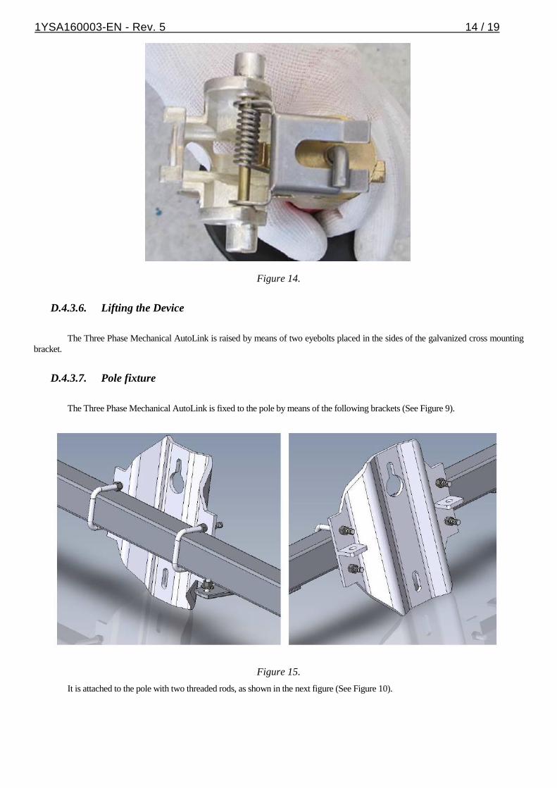
Turn the tripping pin 90°, until the lower contact is firmly blocked (See Figure 8).
1YSA160003-EN - Rev. 5 14 / 19
Figure 14.
D.4.3.6. Lifting the Device
The Three Phase Mechanical AutoLink is raised by means of two eyebolts placed in the sides of the galvanized cross mounting
bracket.
D.4.3.7. Pole fixture
The Three Phase Mechanical AutoLink is fixed to the pole by means of the following brackets (See Figure 9).
Figure 15.
It is attached to the pole with two threaded rods, as shown in the next figure (See Figure 10).

1YSA160003-EN - Rev. 5 15 / 19
Figure 16.
1YSA160003-EN - Rev. 5 16 / 19
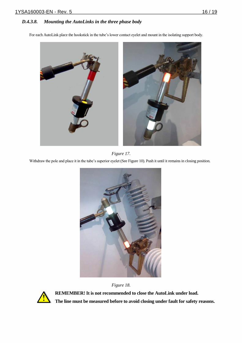
D.4.3.8. Mounting the AutoLinks in the three phase body
For each AutoLink place the hookstick in the tube’s lower contact eyelet and mount in the isolating support body.
Figure 17.
Withdraw the pole and place it in the tube’s superior eyelet (See Figure 10). Push it until it remains in closing position.
Figure 18.
REMEMBER! It is not recommended to close the AutoLink under load.
The line must be measured before to avoid closing under fault for safety reasons.

1YSA160003-EN - Rev. 5 17 / 19
D.5. Commissioning
D.5.1. General procedures
When commissioning, all operations must be carried out by suitable qualified
customer personnel with in-depth knowledge of the apparatus and the installation
itself.
It is not recommended to open AutoLink under charge using a common hookstick, as
it could cause an arc that might damage the personnel or the equipment. The
AutoLink has horns to be used with a load break tool.

1YSA160003-EN - Rev. 5 18 / 19
Section E: Maintenance
Test the correct operation of each electronic sectionalizer on a regular basis, preferably while maintenance on upstream recloser is
made:
- Check the closing system.
- Check that the interlocking bolt turns freely. The tensioning device support should move easily and the spring should be
sufficiently tightened so that the support may reset when the system opens following the operation of the sectionalizer.
- Check that the mobile lever and the lower support of the AutoLink move easily at the joint. Clean and lubricate the joint surfaces
of both pieces.
- Keep contact zones clean and place a thin film of conductive grease on those zones.
- Keep the tripping pin clean.
- Check the upper contact cap is correctly fastened and both the o-ring and the silicon grease are present.
Test should be carried out on a laboratory with the appropriate equipment to simulate service conditions. For this operation it is
recommended to contact ABB to request the testing procedure.
1YSA160003-EN - Rev. 5 19 / 19
ABB S.A.
Power Products Medium Voltage
Jose I. Rucci 1051.
Valentin Alsina (B1822CJU)
Buenos Aires. Argentina.
Telephone: +54 11 4229 5500
www.abb.com.ar
©Copyright 2015 ABB, All rights reserved
Document Title:
Three Phase Mechanical AutoLink User Manual
Document No.
1YSA160003-EN
Date & Rev. Ind.
Feb 2015 - Rev 5
No. of Pages
19
Page
19