instruction manual - tecdriver
TRANSCRIPT

ADLEEPOWER
INSTRUCTION MANUAL
THANK YOU VERY MUCH FOR YOUR PURCHASEOF ADLEE PRODUCTS.PLEASE READ THIS INSTRUCTION MANUALBEFORE INSTALLATION.
R
AM Brushless motors & BL drives

CONTENTS
1. PREFACE
2. RECEIVING
3. ENVIRONMENTAL REQUESTS
4. SPECIFICATION
5. DIMENSIONS
6. DIGITAL OPERATION PANEL .
7. TERMINALS AND WIRING
8. OPERATION AND CONNECTION
9. TROUBLE SHOOTING
Appendix
1
4
5
7
9
15
16
22
61
62

1. PrefaceThank you for purchasing ADLEEPOWER AM Brushless DC motorand BL drives. Please read this manual thoroughly before installa-tion and operation.This manual should be stored by the user for maintenance refer-ence and inspection. Indicated a potentially hazardous situation which, if not avoided, could result in death or serious personnel injury.
Indicates a potentially hazardous situation which, if not avoided, may result in minor or moderate personnel injury and damage to equipment.
Danger!
Caution!
Danger
Only commence wiring after verifying that the power supply is turned OFF. Wiring should be performed only by qualified personnel. Make sure to connect the ground terminal. Ground resistance 0.1 or less. Do not measure any element signal during operation. Failure to observe this caution can result in personal injury. Perform maintenance or inspection only after verifying that the CHARGE LED goes OFF 5 minute and after the main circuit power source is turned OFF. Never modify the product. Failure to observe this warning can result in an electrical shock or personal injury and will invalidate the guarantee.
!
℃
!
Ω
1
Caution
Mount the driver on nonflammable material.(i.e. metal) When mounting units in an enclosure, install a fan or other cooling device to keep the intake air temperature below 45 . Overheating may cause a fire or damage to the unit.

!
※
U V W
power input
2
Caution
Please confirm power source voltage to driver input rated voltage. Please make sure the wiring is correct when driver adds a braking resister. Do not put the advance phase capacitor between the driver and motor. is grounding symbols. Be sure ground both the driver and motor. Check the power connecter is locked on the terminal of driver. ( Do not looseness, otherwise, connecter will be oxidized and over heat.) Check that the input power source voltage is correct. Be sure to connect the power source to L1,L2(input terminals) and the motor to U.V.W.(output terminals). (Wrong connection will damage the driver.)
Do not make any replacement for electronic parts when troubles are occurred. Do not perform a withstand voltage test of the driver. It may cause semiconductor parts or power switches to be damage. Do not install relay between power source and driver for operating start and stop.
Phase advancingcapacitor
ON - OFFMotor
powersource Motor
BL
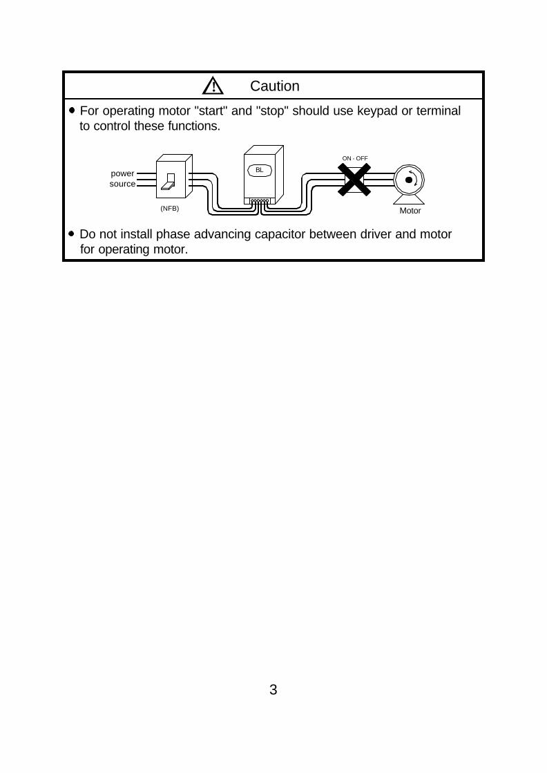
! Caution
For operating motor "start" and "stop" should use keypad or terminal to control these functions.
Do not install phase advancing capacitor between driver and motor for operating motor.
3
ON - OFF
(NFB)
power
Motor
source
BL

4
Motor Drive AM - XXX L (B) BL X - X XX X
: Rated power : example 370 represent 370W : Rated speed : L : 2000RPM M : 3000RPM H/HX : 6000RPM : With B : with magnet brake : Rated voltage : 2 : 220V 4 : 440V : 1 : single phase input 3 : three phase input : 01 : 0.1KW 02 : 0.2KW 04 : 0.4KW 07 : 0.75KW 15 : 1.5KW 22 : 2.2KW
1 2 3 4 512
34
6
56
ADLEEPOWERMATCHSERVO MOTOR
ADLEE POWERTRONIC CO., LTD.
TYPEVOLTSAMP.SAMB
R.P.M
IPOutput
INS.DRIVEDATE
AM-750MAC220V
3.545°C/113°F
3000
750W54B
R
Manufacturing date
Drive model
Implied protection
Rated powerModel No.
Input voltage
Rated current
Ambinent Temp
Max. rpm
Insulation gradeBL2-107
AC-INPUT AC-OUTPUT
1 max 8.5A200~230V 50/60Hz
ADLEE POWERTRONIC CO., LTD.
ψ 370W max 4.9A0~230V 3ψ
MATCHSERVO MTR DRIVESBL2 - 104L
R
Input voltage & frequency
Model no
Output voltage & phase
Rated output power &Max. currentInput phase &
Max. input current
2. Receiving2-1 Acceptance Inspection and Precautions During product manufacturing, packaging, and shipment have been standardised. If any problem is discovered, please contact your dealer or producer immediately. Any damage with each product after shipping. The instruction manual is contained in the package. The product as same as an order (check the nameplate, voltage and frequency). All of terminals are locked and unusual substance. The keyboard of remote control must be corrected. Check the additional accessories.2-2 Nameplate Motor
Drive
2

3. Environmental requests
Operation
Storage
Transportation
Note : a. Bad installation can reduce product service life. b. Do not put motors and drives into worse environment. Such as high temperature/humidity/vibration, corrosiveness gas, burst. c. Keep enough cooling space for motors and drives.
Air temperature -20~60 (-4~140 )℃ ℉
Air pressure 86~106kPa
Humidity Less than 90%, no frosting
Air temperature -20~60 (-4~140 )℃ ℉
Air pressure 86~106kPa
Humidity Less than 90%, no frosting
Vibration Less than 20HZ : maximum 9.86m/s2
20~50HZ : maximum 5.88m/s2
5
Air temperature -10~45 (14~113 )℃ ℉
Air pressure 86~106kPa
Attitude Under 1000 meters
Vibration Less than 20HZ : maximum 9.86m/s2
20~50HZ : maximum 5.88m/s2

10cm
10cm
MotorsDrives
5cm 5cm
6

4. Specification
7
The varnished copper wire is F class insulation. AM-60~370 motor has magnet brake option. The brake torque is 25Kg-cm (21.6in-lb) and BL driver offers 24VDC to control it directly.
※ ∮
※ ∮
±
Ω
Ω
Rated Power W 60 90 120 180 250 370
Motor No. AM-60L/M
AM-90L/M/H
AM-120L/M/H
AM-180L/M/H
AM-250L/M/H
AM-370L/M/H
Drive No. BL2-101 BL2-101 BL2-102 BL2-102 BL2-104 BL2-104
Input Voltage 220V 10% 1ψ
Input Frequency HZ 50 / 60
Max. input current 3.5 3.8 5.5 5.8 10.8 11
Motor Phase 3ψ
Rated Torque Kg-cm (in-lb)
2.9/2.0(2.5/1.7)
4.4/2.9/1.5(3.8/2.5/1.3)
5.8/3.9/2.0(5.0/3.4/1.7)
8.8/5.8/2.9(7.6/5.0/2.5)
12.0/8.1/4.0(10.4/7.0/3.5)
18.0/12.0/6.0(15.6/10.4/5.2)
Rated Speed RPM L/M/H : 2000 / 3000 / 6000
Max. Efficiency % > 80 > 80 > 80 > 80 > 80 > 80
Max. Output W 210 270 360 450 750 900
Max. Torque Kg-cm (in-lb)
10.5/7.0(9.1/6.1)
13.2/8.7/4.5(11.4/7.5/3.9)
21.0/14.0/7.0(18.2/12.1/6.1)
26.4/17.4/8.7(22.9/15.1/7.5)
45.0/30.0/15.0(39.0/26.0/13.0)
54.0/36.0/18.0(46.8/31.2/15.6)
Variable Speed RangeRPM L : 0~2000 M : 0~3000 H : 0~6000
Acc. Dec. Time 0.1 ~ 600.0 Sec
Speedregulation
Load ±1% Below (0~Rated Torque at rated speed)
Voltage ±1% Below (Source voltage± 10% at rated speed No Load)
Temperat-ure ±1% Below (-10~45 / 14~113 at rated speed No Load)℃ ℉
Motor Insulation/Max. Working TEMP. B Class ( 130 /266 ) / Max. 100 /212※ ℃ ℉ ℃ ℉
Type of control Rectangular wave PWM
Speed command
1. Built-in potentiometer2. External Potentiometer 2 k≧3. 0~5VDC, 0~10VDC, 4~20mA control4.RS485
Operation
1. Pannel : CW、CCW、Key2. Terminal : Type of input:Photocoupler, input impedance 2.2 k / CW、CCW、Common (4.5 ~ 5VDC)3. Communication : RS485
Output signal Open collect output, External use condition DC5V、10mA belowSPEED OUT、Fault relay A/B
Protection
Any phenomenons as below will come to stop output alarm signal will be output and themotor. Over load:Motor working temperature is not over 100℃(212 ℉). Over heat:Power modular over heat shut down itself. Lost phase:Motor signals are abnormal, due to motor cables was broken or discounector. Phase to phase short circuit.
Motor enclosure type IP40
Figure No. 1 1 2 3 4 5 4(M/H)
Motor Weight Kg (lb)
2.1/2.1(1.8/1.8)
2.4/2.4/2.4(2.1/2.1/2.1)
2.6/2.5/2.5(2.3/2.2/2.2)
2.9/2.7/2.7(2.5/2.3/2.3)
4.0/3.8/3.7(3.5/3.3/3.2)
4.5/4.0/4.0(3.9/3.5/3.5)
BL Driver Weight Kg (lb)
1.1(1.0)
1.1(1.0)
1.1(1.0)
1.1(1.0)
1.1(1.0)
1.1(1.0)

±
Ω
Ω
8
AM-750~2200 has magnet brake option. The brake torque is 160Kg-cm(135in-lb).※ ∮
Rated Power W 750 1000 1500 2200
Motor No.AM-750M/H
CM-750L/HX AM-1000M/HAM-1500M/H
CM-1500L/HXAM-2200M/H
CM-2200L/HX
Drive No. BL2-107 BL2-115 BL2-115 BL2-122
Input Voltage 220V 10% 1ψ
Input Frequency HZ 50 / 60
Max. input current 16 20.4 26 38
Motor Phase 3ψ
Rated Torque Kg-cm (in-lb)
AM:24.4/12.2 (21.1/10.6)CM:36.6/12.2 (31.7/10.6)
AM:32.5/16.2 (28.2/14.0)
AM:48.8/24.4 (42.3/21.1)CM:73.2/24.4 (63.4/21.1)
AM:73.2/36.6 (63.4/31.7)CM:109.8/36.6 (95.1/31.7)
Rated Speed RPM L/M/H/HX : 2000/3000/6000/6000
Max. Efficiency % > 85 > 85 > 85 > 85
Max. Output W 1600 2300 3000 4000
Max. Torque Kg-cm (in-lb)
AM:70.0/35.0 (60.6/30.3)CM:95.0/24.0 (82.3/20.8)
AM:110.0/55.0 (95.3/47.6)
AM:120.0/60.0 (103.9/52.0)CM:160.0/45.0 (138.6/39.0)
AM:180.0/90.0 (155.9/77.9)CM:210.0/72.0 (181.9/62.4)
Variable Speed RangeRPM
L : 0~2000 M : 0~3000 H : 0~6000
Acc. Dec. Time 0.1 ~ 600.0 Sec
Speedregulation
Load ±1% Below (0~Rated Torque at rated speed)
Voltage ±1% Below (Source voltage± 10% at rated speed No Load)
Temperat-ure
±1% Below (-10~45 / 14~113 at rated speed No Load)℃ ℉
Motor Insulation/Max. Working TEMP.
B Class ( 130 /266 ) / Max. 100 /212※ ℃ ℉ ℃ ℉
Type of control Rectangular wave PWM
Speed command
1. Built-in potentiometer2. External Potentiometer 2 k≧3. 0~5VDC, 0~10VDC, 4~20mA control4. RS485
Operation
1. Pannel : CW、CCW、Key2. Terminal : Type of input:Photocoupler, input impedance 2.2 k / CW、CCW、Common (4.5 ~ 5VDC)3. Communication : RS485
Output signal Open collect output, External use condition DC5V、10mA belowSPEED OUT、Fault relay A/B
Protection
Any phenomenons as below will come to stop output alarm signal will be outputand the motor. Over load:Motor working temperature is not over 100℃(212 ℉). Over heat:Power modular over heat shut down itself. Lost phase:Motor signals are abnormal, due to motor cables was broken or discounector. Phase to phase short circuit.
Motor enclosure type L/M:IP54 H/HX:IP40
Figure No.AM:6
CM:A/D AM:7AM:8
CM:B/EAM:9
CM:/C/F
Motor Weight Kg (lb)
AM:8.0/7.8 (6.9/6.8)CM:11.0/14.2 (9.5/12.3)
AM:9.4/8.7(8.1/7.5)
AM:11.0/9.7 (9.5/8.4)CM:14.0/15.3
(12.0/13.2)
AM:13.2/16.5 (11.4/14.3)CM:15.6/16.5
(13.5/14.3)
BL Driver Weight Kg (lb)
1.3(1.1)
1.3(1.1)
1.3(1.1)
1.3(1.1)

5. Dimensions5-1 Drive dimensions BL2-101~107
Unit : mm
9

BL2-115~BL2-122Unit : mm
10

5-2 Motor dimensions AM-60~370
Unit : mm
11
Wires colors : U(red), V(white), W(black).
No. P M∮ S∮ N∮ T LA LB L1 L2 AD A B1 B2OUTPUT SHAFT END
ED Q E D∮ GA F
1
90 104 8.5 83 2.5 8
100 128 161
109 27 61 33
20 25 2812 13.5 4
2115 147 180
25 29 323
14 16 54 170 202 235
5 185 217 250

AM-750~AM-2200Unit : mm
12
No. P M∮ S∮ N∮ T LA LB L1 L2 B1 B2 AD AE LDOUTPUT SHAFT END
ED Q E D∮ GA F DH
6
130 145 9 110 3.5 12
178 218 252.3
117 34.3 165.5 146
63 35 40 40 19 21.5 6 M6
7 195 245 279.3 80
45 50 50 24 27 8 M88 212 262 296.3 97
9 232 282 316.3 117
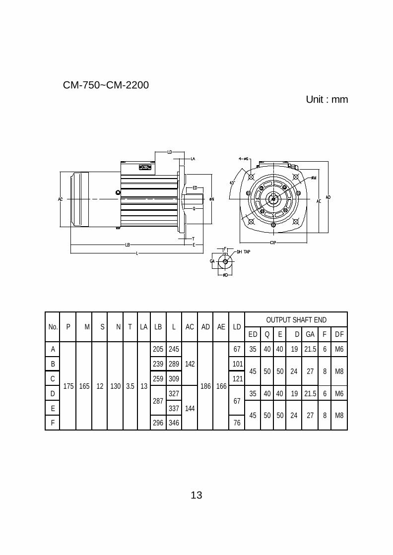
CM-750~CM-2200Unit : mm
13
No. P M∮ S∮ N∮ T LA LB L AC AD AE LDOUTPUT SHAFT END
ED Q E D∮ GA F DF
A
175 165 12 130 3.5 13
205 245
142
186 166
67 35 40 40 19 21.5 6 M6
B 239 289 10145 50 50 24 27 8 M8
C 259 309 121
D287
327
14467
35 40 40 19 21.5 6 M6
E 33745 50 50 24 27 8 M8
F 296 346 76

5-2 F306 dimensions
Unit : mm
14

6. Digital operation panel
REV FWD
FUNC
STOPPROG
BL2 IPM
FUNC
STOP
F306 FWD
CHARGE
REV
REMOTE CONTROL
PROG
FUNC
STOP
15
Keypad Function Description
Forwardrun Commands forward run
Reverserun Commands reverse run
Cursormovement Select the digit
Down Decrease the parameter value 9~0
Up Increase the parameter value 0~9
Memorystorage Saves the setting parameter value
Function Press once to select function code andpress again to change its content
Stop Stop operation / Escape to standby mode
Note for HX RPM number on display:The RPM number has been divided by 10. Ex, CD04=26means CD04=260RPM. This division does not effect onRS485 communication. It is for display only.

7. Terminals and wiring7-1 Main power circuit terminals
7-2 Control terminals
16
L1 L2 U V W PRP
MotorPower
GroundExternal braking resistorRefer to the appendix
Source
OUTSPEEDA/B C CWCF CCW EXG H24V M L
MB+MB-
Main circuit terminal
No. Symbol Terminal name Description
1 Ground Ground (Earth) Terminal
2 L1 Connect powersupply (L1, L2) Single Phase
3 L2
4 U
Driver outputTerminal connecting tomotorU(red), V(white), W(black)
5 V
6 W
7 P Dynamic brakeresistor
See appendix for brakingresistor selection8 PR
+24 EXTERNAL POWER INPUT
SPEED SELECTION
CW. Input
CCW. Input
SPEED OUTPUT
OFFON
ONOFF
OFFON
8 INPUT COM3 CF
4 CW
5 CCW
1 A/B
6 SPEED OUT
2 C
9 H
10 M
11 L
EXG
3
2
1 3
21
SPEED KNOB(OPTIONS)
EXG
EXG

7-3 Control terminals descriptions
All terminal can connect to switch, relay, TTL or Transistor. Referto 8-3 for detail.
17
SPEEDCWCF CCW EXG 24VOUT
A/B C H M L
J4 J5 S161 J8
J6MB+MB-
HallRS485sensor
No Symbol Terminal name Description
1 A/B Alarm outputFault alarm contact. Set J4 jumper for A(normal open) or B (normal close).
2 C Alarm output common Fault alarm contact C.
3 CFAnalog and digitalspeed input selection
CF/EXG open : Analog speed input is frompanel VR or F306 VR. Digital speed input isCD28 setting. Set J5 jumper for panel VR orF306 VR selection.CF/EXG short : Analog speed input is fromexternal VR by H M L terminals. Digital speedinput is CD29 setting.
4 CW Forward operation Forward operation / stop terminal.
5 CCW Reverse operation Reverse operation / stop terminal.
6 SPEED OUT Speed signal outputL, M model : 12 pulses/turnH, HX model : 6 pulses/turn
7 EXG Common terminal Common for terminal 3~6.
8 24V Input COM +24VDC external power input. Set S161jumper to select internal or external power.
9 H +10 VDC External VR reference voltage.
10 MAnalog commandinput
External analog speed command input. Set J6jumper for voltage 0~5VDC, 0~10VDC or4~20mA.
11 L H and M common
MB- Motor brake - 24VDC, 15W
MB+ Motor brake +

7-4 Jumpersa. S161 for INT/EXT reference voltage input (Default value is INT reference voltage input)
b. J5 for panel VR or F306 VR(Default value is panel VR)
c. J4 for fault alarm A (normal open) or B (normal close) (Default value is fault alarm A.
d. J8 for external speed command voltage 0~5V or 0~10V (Default value is 0~10V)
e. J6 for H M L input signal selection (Default value is 0~10V)
INT EXT
F306 VR
18
Panel VR
Fault alarm A Fault alarm B
0~5V 0~10V
0~5V 0~10V 4~20mA

7-5 Hall sensor connector
7-6 RS485 connector
7-7 Wiring7-7-1 Wiring for main circuit
8765 4321
8765 4321
This connector is for both F306 and RS485. Set CD02 for selection.※
19
NO 8 7 6 5 4 3 2 1
Color Black Red Orange Yellow Green Blue Purple Brown
Symbol GND VCC GND A RFA0 B 3.3V
Connect to F306 or RS485
NO 8 7 6 5 4 3 2 1
Color Black Red Brown Green Yellow Orange Purple Blue
Symbol GND VCC HC HB HA TH2 TH1
Connect to Hall sensor / NTC
L1
L2
E
U
V
WFilter
IM

7-7-2 Wiring equipments Select the wiring equipment, refer to the table below. 1. On the input power side, a molded case circuit breaker (MCCB) to protect driver primary wiring should be in stalled. 2. A leakage current breaker threshold of 200mA and above is recommended. 3. Use of input side magnetic contactor. An input MC can be used to prevent an automatic restart after recovery from an external power loss during remote control opera- tion. However, do not use the MC reduced reliability. 4. In general, magnetic contactors on the output of the driver should not be used for motor control. Starting a motor with the driver running will cause large surge cur- rents and the driver overcurrent protector to trigger.
20
Model BL2
Model No 01 02 04 07 15 22
Capacity (KVA) 1.0 1.0 1.0 1.6 2.7 3.8
Current (A) 2.5 2.5 2.5 4.1 7 10
Circuit Breaker(MCCB) (A) 10 10 10 10 15 20
Electro-MagneticContactor (A) 12 12 12 12 12 12
Thermal relay RCvalue (A) 2.4 2.4 2.4 3.8 6.8 9
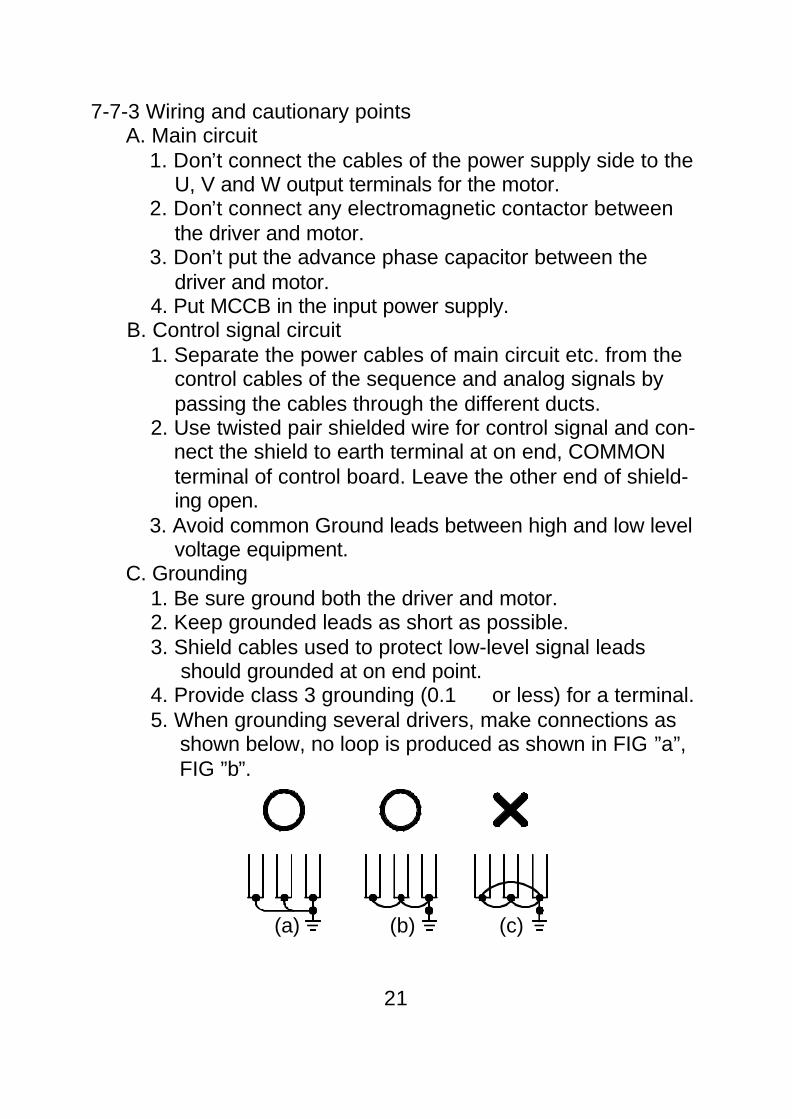
7-7-3 Wiring and cautionary points A. Main circuit 1. Don’t connect the cables of the power supply side to the U, V and W output terminals for the motor. 2. Don’t connect any electromagnetic contactor between the driver and motor. 3. Don’t put the advance phase capacitor between the driver and motor. 4. Put MCCB in the input power supply. B. Control signal circuit 1. Separate the power cables of main circuit etc. from the control cables of the sequence and analog signals by passing the cables through the different ducts. 2. Use twisted pair shielded wire for control signal and con- nect the shield to earth terminal at on end, COMMON terminal of control board. Leave the other end of shield- ing open. 3. Avoid common Ground leads between high and low level voltage equipment. C. Grounding 1. Be sure ground both the driver and motor. 2. Keep grounded leads as short as possible. 3. Shield cables used to protect low-level signal leads should grounded at on end point. 4. Provide class 3 grounding (0.1 or less) for a terminal. 5. When grounding several drivers, make connections as shown below, no loop is produced as shown in FIG ”a”, FIG ”b”.
(a) (b) (c)
Ω
21

8 Operation and connection8-1 Parameter list
22
Displaycode
Function Default ValueAdjustRange
Unit Remark
CD01 Reserved
CD02Commandmode
1 0~70~3 : Close loop control4~7 : Open loop control
CD03 Brake mode 1 0~10 : Free run to stop1 : Stop with deceleration time
CD04Maximumspeed limited
2000/3000/6000HX:15000
130~6000HX:260~15000
RPM
CD05Minimum speedlimited
00~6000
HX:0~15000RPM
CD06SpeedcommandRPM/5V
2000/3000/6000HX:15000
1000~7000HX:1000~15000
RPM
CD07SpeedcommandRPM/0V
0-500~500
HX:-1500~1500 RPM
CD08Accelerationtime
0.2 0.1~600.0 SEC
CD09Decelerationtime
0.2 0.1~600.0 SEC
CD10 S curve 3.0 0.2~15.0
CD11 4~20mA 0 0~1
CD12 KP (P gain) 100 10~200 mv/RPM
CD13 KI (I gain) 80 30~300 ms
CD14Hall sensorposition off setshift
10 0~30
CD15 Display ratio 1 1~200

23
STOP
STOP
Displaycode Function Default Value
AdjustRange Unit Remark
CD16ACC./DEC.curve
0 0~10 : Linear1 : S curve
CD17 Current limit 300/270 20~300/20~270 %750W : 300%≦>750W : 270%
CD18 Direction limit 4 0~7
0 : CW and CCW, need before change direct1 : CW only2 : CCW only4 : CW and CCW, do not need before change direction
CD19Analog/digitalspeed input 0 0~1
CD20 Fast stop 0 0 or 1
CD21 Address setting 1 0~99
CD22Transmissionspeed
3 0~3
CD23Transmissionfault treatment 3 0~3
CD24Communicatorprotocol
0 0~11
CD25Communicationloss time detect
0.5 0.1~100.0 SEC
CD26Communicationloss 3 0~3
CD27Communicationerror detect
3 1~10
Communication address description
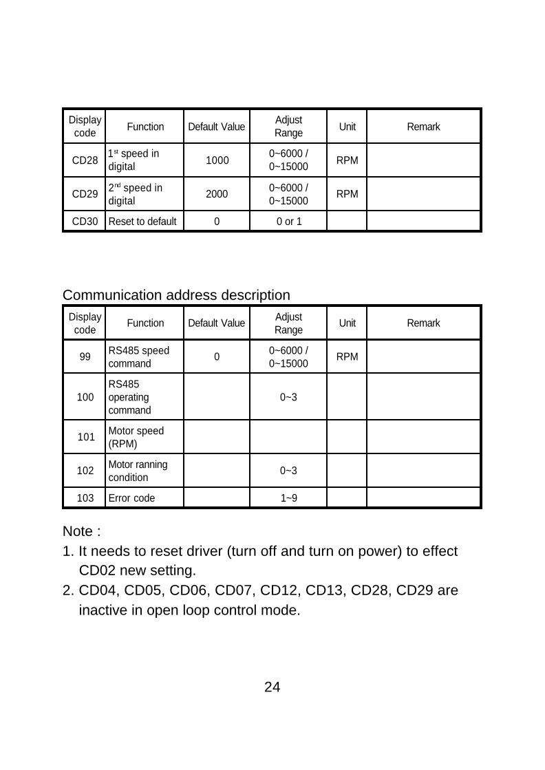
Note :1. It needs to reset driver (turn off and turn on power) to effect CD02 new setting.2. CD04, CD05, CD06, CD07, CD12, CD13, CD28, CD29 are inactive in open loop control mode.
24
Displaycode Function Default Value
AdjustRange Unit Remark
CD281st speed indigital 1000
0~6000 /0~15000 RPM
CD29 2nd speed indigital
2000 0~6000 /0~15000
RPM
CD30 Reset to default 0 0 or 1
Displaycode
Function Default Value AdjustRange
Unit Remark
99 RS485 speedcommand
0 0~6000 /0~15000
RPM
100RS485operatingcommand
0~3
101 Motor speed(RPM)
102 Motor ranningcondition
0~3
103 Error code 1~9

8-2 Parameter setting sequence
A. In standby condition, press to be in setting model. Press if it is not in standby mode.
B. Press to the parameter number. Press to return to standby mode if there is no need to change value.
C. Press to show parameter setting value. Press to return to parameter number and press to return to standby mode, if there is no need to change value.
D. Press to the need value.
E. Press to save changes and return to standby mode.
F. Press or to operate motor.
Note for HX RPM number on display:The RPM number has been divided by 10. Ex, CD04=26 meansCD04=260RPM. This division does not effect on RS485 communi-cation. It is for display only.
FUNC
STOP
FUNC
PROG
25
PROG
FUNC
PROG

8-3 Command source settingPanel, terminal, RS485 and remote control (F306) are the com-mand source for selection. Use CD02 to select it. Panel commandis effective always.A. Panel a. Analog/digital speed input a-1. CD19=0 analog input Panel’s VR is 1st speed. Display is flashing to show the setting speed. Analog input on H M L terminal is 2nd speed. Set CF/ COM close to select 2nd speed. Display is flashing to show the setting speed. a-2. CD19=1 digital input 1st speed is CD28 value and 2nd speed is CD29 value. Use to set speed, then press to save setting. Set CF/COM close to select CD29 2nd speed. Use can change speed in operation condition in digital speed input mode. Press or to change speed. Repeat to press or if it does not re- sponse in 5 seconds. In the speed change mode: (1) Press keypad once : change 1 RPM intermittently. (2) Continute to press keypad : change 1 RPM in first 10 seconds and change 10 RPM after first 10 sec- onds. b. Press or to operate motor. c. Press to stop motor. d. Use CF terminals to do two speeds control. CF/COM open is 1st speed. CF/COM close is 2nd speed.B. Remote control (F306) Same as Panel control.C. Communication (RS485) Please refer to CD21 to address 103 for detail description.
PROG
26
STOP

D. Terminal control 1. Set CD02=0 or 4. 2. Set S161 jumper at INT if using internal power. 3. Example : 1st and 2nd speed control.
Note :a.Use CW/CCW switch to control motors RUN/STOP. Do not use power ON/OFF to control motors RUN/STOP.b.Motor follows the ACC./DEC. time if CW/CCW is switched dur- ing operation.c.Analog input : Panel VR or F306 VR is 1st speed and HML com- mand is 2nd speed.d.Digital input : CD28 setting is 1st speed and CD29 setting is 2nd
speed.
27
`
CFOFF “HIGH”
ON “LOW”
CCWOFF “HIGH”
ON “LOW”
CWOFF “HIGH”
ON “LOW”
CCW
CW
Motorsoperationmodel
1st speed2nd speed
Run/Speedchange/Stop
Run /Immediately stop
Immediatelyreverse

3.Signal input circuit
EXT voltage is 24VDC ± 10% Using internal power supply control Set S161 jumper at INT. motor cannot operate if S161 jumper is at EXT. <Non-contact control>
INPUTCOM
INPUT
EXG
EXT.
INT. S161 jumper
Photocoupler
CFCWCCW
■
28
INPUT
EXG
Photocoupler
BL Drivers Controller
INPUT
EXG
BL DriversController
Compatible withTTL 7406
■

<Contact control>
Using external power supply control■
Set S161 jumper atINT.
29
INPUT
EXG
BL DriversController
Relay
INPUTCOM
INPUT
EXG
BL Drivers
GND
Transistor
DC24V
Controller

Note : controller with built-in clamp diode
It is necessary to set S161 jumper at EXT, when controller withbuilt-in clamp doide has been used. If S161 jumper setting is notcorrect, then motors will run at controller power ON/OFF.
4.Signal output circuit4-1 Signal output circuit
External power supply DC voltage should less than 26.4V and current should less than 10mA. Select suitable current limit resistor based on DC power supply voltage.
■
30
EXT. Compatiblewith TLP521
INPUTCOM
INPUT
EXG
INT.
BL Drives
+24V
Transistor
Clamp diode
Controller
560Ω
Photocoupler
EXG
SPEEDOUT

4-2 Example of application of signal output circuit
[Speed out]H, HX series : 6 pulses/per turnL, M series : 12 pulses/per turnMotor speed can be measured from the frequencies of terminal“SPEED OUT”.
Motor speed(r/min)= × 60
= Frequency of speed out
The pulse width depends on the motor speed.That is, the faster the motor runs, the narrower the width is.
[Alarm Out]1. Any fault occurs, alarm will output.2. Set J4 jumper for A (normal open) or B (normal close).3. Regarding type of protection, please refer to “TROBLE SHOOTING”.
T1
Dreves
To external power supplyCurrent limitresistor
T
Frequency of speed out (HZ)6 or 12
31
EXG
Current limitresistor 2.7KΩ
Controller
SPEEDOUT
DC24V
BL Drives
Photocoupler

8-4 Parameter description
Command mode
CD02
0 : Terminal command in close loop control.1 : Panel or F306 command in close loop control. (Default value)2 : Panel or communicator command in close loop control.3 : Speed command by RS485 and operate command by terminal in close loop control.4 : Terminal command in open loop control.5 : Panel or F306 command in open loop control.6 : Panel or communicator command in open loop control.7 : Speed command by RS485 and operate command by terminal in open loop control.Note : 1.New setting needs to be effected by reset driver (turn off and turn on power) 2.In mode 4~7, display shows DUTY in standby mode and motor real speed in running mode. 3. In mode 4~7, the speed duty can be set by panel VR or HML external analog signal only.
Setting Range 0 ~ 1
Default value 1
0 : Free run to stop.1 : Stop with deceleration time. (Default value)
32
Brake mode
CD03
Setting Range 0 ~ 7
Default value 1

Maximum speedlimit
CD04
0 5V(10V)VOLT(CMD)
2500
3000
RPM
Ex. CD04=2500
Setting Range130 ~ 6000 /260 ~ 15000
Default value 2000(L) / 3000(M)/ 6000(H) /15000(HX)
0 5V(10V)VOLT(CMD)
150300
RPM
Minimum speedlimit
CD05
Ex. CD05=300
To get better close loop control performance, the L/M series needto set over 150RPM and the H/HX series need to set over300RPM. Please note, the L/M series cannot work at 1~129RPMand the H/HX series cannot work at 1~259RPM.Note : This parameter does not work in open loop control.
Setting Range 0 ~ 6000 /0 ~ 15000
Default value 0
33
Note : This parameter does not work in open loop control.

The reference speed command at 5V(10V)(20mA) in close loop.Note : This parameter does not work in open loop control.
Speed commandRPM / 0V
CD07
The reference speed command at 0V/4mA in close loop.Note : This parameter does not work in open loop control.Ex. 2000RPM at 4.5V, 0RPM at 0.5V CD06=2250, CD07=-250, CD04=2000
34
Speed commandRPM / 5V
CD06
Setting Range 1000 ~ 7000 /1000 ~ 15000
Default value2000/3000/6000/
15000
Setting Range -500 ~ 500 /-1500 ~ 1500
Default value 0
0.5 5V(10V)VOLT(CMD)
-250
2000
RPM
Acceleration time
CD08
The acceleration time from 0 RPM to CD04 RPM. The accelera-tion time is influenced with the value of S curve, KP and KI.
Setting Range 0.1 ~ 600.0second
Default value 0.2 seconds

Deceleration time
CD09
The deceleration time CD04 RPM to 0 RPM. The decelerationtime is influenced with the value of S curve, KP and KI.Note : If CD09=0.2 is still too slow, set CD20=1.
S curve
CD10
Set soft acceleration/deceleration operation. The real accelera-tion/deceleration time will be longer than CD08 and CD09 settingif set CD16=1.
35
Setting Range 0.2 ~ 15.0
Default value 3.0
4~20mA
CD11
Setting Range 0 ~ 1
Default value 0
0 : Normal(HML analog input)(Default value)1 : 4~20mA
KP ( P gain )
CD12
Higher value is with faster response, it can be overshoot if valueis too high. This parameter does not work in open loop control.
Setting Range 10 ~ 200
Default value 100
Setting Range0.1 ~ 600.0
second
Default value 0.2 seconds

KI ( I gain )
CD13
Lower value is with faster response. This parameter does notwork in open loop control.
Adjust motor hall sensor position in phase advance.Positive value is phase advance for CW operation. Current signalmay be in phase behind condition when motor is running at highspeed. This parameter can improve performance.
36
Hall sensorposition off set
shift
CD14
KP+(KI/S)+
- Feedback speed
Speed command
Setting Range 0 ~ 30
Default value 10
Setting Range 30 ~ 300 ms
Default value 80 ms
Display ratio
CD15
Setting Range 1 ~ 200
Default value 1
Display speed = (set or real speed) / CD15This functiion is good for motor with gearbox. The display canshow the gearbox output speed.

ACC./DEC. curve
CD16
Setting Range 0 ~ 1
Default value 0
0 : Linear. (Default value)1 : S curve.
Current limit
CD17
Higher value has higher output torque, but it may occur overheatproblem.Setting range : ≦ 750W : 300% > 750W : 270%
37
CD04
CD16=0 CD08
CD04
CD16=1 CD08
rpm
rpm
t (sec)
t (sec)
Higher CD10 value needs longer time to reach CD04 setting.
Setting Range 20 ~ 300% or20 ~ 270%
Default value 300 / 270%
Direction limit
CD18
0 : CW and CCW, need before change direct.1 : CW only.2 : CCW only.4 : CW and CCW, do not need before change direction.5~7 : Reserved.
STOP
STOP
Setting Range 0 ~ 7
Default value 4

Analog / digitalspeed input
CD19
Setting Range 0 ~ 1
Default value 0
0 : Analog command is from pannel/F306 VR or H M L terminal.1: Digital command is from panel or F306 and worked with CD28 or CD29 setting.
38
Address setting
CD21
Each drive must have unique identified address if they are con-trolled by RS-485 communication. Each address cannot be dupli-cated.
Setting Range 0 ~ 99
Default value 1
CD20=0: Deceleration time is following CD09 setting.CD20=1: Motor speed is decelerating by maximum ability.
Fast stop
CD20
Transmissionspeed
CD22
Setting the transmission speed between computer and drive.0 : 2400 bits/second.1 : 4800 bits/second.2 : 9600 bits/second.3 : 19200 bits/second.
Setting Range 0 ~ 3
Default value 3
Setting Range 0 or 1
Default value 0

39
Transmissionfault treatment
CD23
0 : Alarm and keep operation.1 : Alarm and decelerate to stop.2 : Alarm and free run to stop.3 : No alarm and keep operation.
Setting Range 0 ~ 3
Default value 3
Communicatorprotocol
CD24
A. Data format 0 : 8,N,1 RTU (1 start bit+8 data bits+1 stop bit) 8,N,1 RTU(10bits)(character frame in hexadecimal)
1 : 8,N,2 RTU (1 start bit+8 data bits+2 stop bit) 8,N,2 RTU(11bits)(character frame in hexadecimal)
2 : 8,E,1 RTU (1 start bit+8 data bits+1 Even bit+1 stop bit) 8,E,1 RTU(11bits)(character frame in hexadecimal)
3 : 8,O,1 RTU (1 start bit+8 data bits+1 Odd bit+1 stop bit) 8,O,1 RTU(11bits)(character frame in hexadecimal)
Start bit 0 1 2 3 4 5 6 7 Stop bit
Start bit 0 1 2 3 4 5 6 7 Stop bit Stop bit
Setting Range 0 ~ 11
Default value 0
Start bit 0 1 2 3 4 5 6 7Evenparity Stop bit
Start bit 0 1 2 3 4 5 6 7Oddparity Stop bit

4 : 7,N,1 ASCII (1 start bit+7 data bits+1 stop bit) 7,N,1 ASCII(9bits)(character frame in hexadecimal)
5 : 7,N,2 ASCII (1 start bit+7 data bits+2 stop bit) 7,N,2 ASCII(10bits)(character frame in hexadecimal)
6 : 7,E,1 ASCII (1 start bit+7 data bits+1 Even bit+1 stop bit) 7,E,1 ASCII(10bits)(character frame in hexadecimal)
7 : 7,O,1 ASCII (1 start bit+7 data bits+1 Odd bit+1 stop bit) 7,O,1 ASCII(10bits)(character frame in hexadecimal)
8 : 8,N,1 ASCII (1 start bit+8 data bits+1 stop bit) 8,N,1 ASCII(10bits)(character frame in hexadecimal)
9 : 8,N,2 ASCII (1 start bit+8 data bits+2 stop bit) 8,N,2 ASCII(11bits)(character frame in hexadecimal)
10 : 8,E,1 ASCII (1 start bit+8 data bits+1 Even bit+1 stop bit) 8,E,1 ASCII(11bits)(character frame in hexadecimal)
40
Start bit 0 1 2 3 4 5 6 Stop bit
Start bit 0 1 2 3 4 5 6 Stop bit Stop bit
Start bit 0 1 2 3 4 5 6Evenparity Stop bit
Start bit 0 1 2 3 4 5 6Odd
parity Stop bit
Start bit 0 1 2 3 4 5 6 7 Stop bit
Start bit 0 1 2 3 4 5 6 7 Stop bit Stop bit
Start bit 0 1 2 3 4 5 6 7Evenparity Stop bit

41
11 : 8,O,1 ASCII (1 start bit+8 data bits+1 Odd bit+1 stop bit) 8,O,1 ASCII(11bits)(character frame in hexadecimal)
B. Communication protocol Data contents are in hexadecimal with postive and negative format.1. RTU
Start A silent interval of more than 10ms
Address 8-bit address
Function 8-bit command
Data (n-1)Contents of data :n*8-bit data, n 30≦
...
Data 0
CRC CHK Low Check sum (CRCL)
CRC CHK High Check sum (CRCH)
End A silent interval of more than 10ms
Start bit 0 1 2 3 4 5 6 7Oddparity Stop bit

2. ASCII
42
≦
STX Start character=' : ' (3AH)
Address Hi Communication address :8-bit address consists of 2 ASCIIcodes.Address Lo
Function Hi Command code :8-bit command consists of 2 ASCIIcodes.Function Lo
Data (n-1)Contents of data :n*8-bit data consist of 2n ASCII codes.(n 30)
...
Data 0
LRC CHK High LRC check sum :8-bit check sum consists of 2 ASCIIcodes.LRC CHK Low
END Hi End characters :END Hi=CR(0DH)END Lo=LF(0AH)END Lo

CRC(Cyclical Redundancy Check) is calculated by the followingsteps:Step 1. Load a 16-bit register (called CRC register) with FFFFH.Step 2. Exclusive OR the first 8-bit byte of the command mes- sage with the low order byte of the 16-bit CRC register, putting the result in the CRC register.Step 3. Shift the CRC registers one bit to the right with MSB zero filling. Extract and examine the LSB.Step 4. If the LSB of CRC register is 0, repeat step 3, else Exclu- sive OR the CRC register with the polynomial value A001H.Step 5. Repeat step 3 and 4 until eight shifts have been per- formed. When this is done, a complete 8-bit byte will have been processed.Step 6. Repeat steps 2 to 5 for the next 8-bit byte of the com- mand message. Continue doing this until all bytes have been processed. The final contents of the CRC register are the CRC value.
LRC (Longitudinal Redundancy Check) is calculated by summingup, module 256, the values of the bytes from Address to last datacharacter then calculating the hexadecimal representation of the2’s-complement negation of the sum.For example, refer to 06H CD04 34+06+00+04+05+DC=1FH LRC HI=E(45), LRC LO=1(33) the 2’s-complement negation of FH is E1H
43
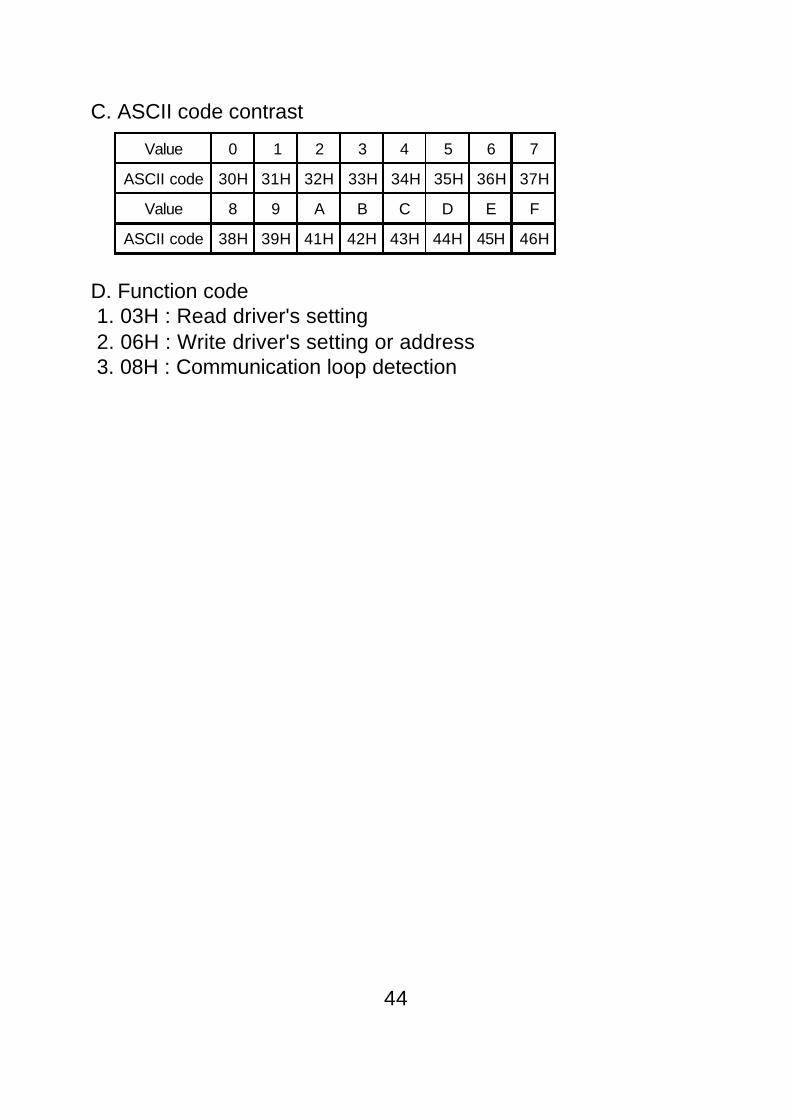
C. ASCII code contrast
D. Function code 1. 03H : Read driver's setting 2. 06H : Write driver's setting or address 3. 08H : Communication loop detection
44
Value 0 1 2 3 4 5 6 7
ASCII code 30H 31H 32H 33H 34H 35H 36H 37H
Value 8 9 A B C D E F
ASCII code 38H 39H 41H 42H 43H 44H 45H 46H

Ex. To read two parameter data address 99(63H)=1500(05DCH) and address 100(64H)=1(01H) from drive address 52(34H).1.RTU
45
Computer command message Drive response message
D1 Address 34H D1 Address 34H
D2 Function code 03H D2 Function code 03H
D3 Start address (H) 00H D3 Quantity of data(count by byte)
04H
D4 Start address (L) 63H D4 CD99 content (H) 05H
D5 # of data (H) 00H D5 CD99 content (L) DCH
D6 # of data (L) 02H D6 CD100 content (H) 00H
D7 CRCL CRCL D7 CD100 content (L) 01H
D8 CRCH CRCH D8 CRCL CRCL
D9 CRCH CRCH
(1) 03H : Read drive's setting
Computer command message D1 : Communication address D2 : Function code D3 : Parameter number (H) D4 : Parameter number (L) D5 : Quantity of parameter (H) (word count) D6 : Quantity of parameter (L) (word count) D7 : CRCL or LRC (H) D8 : CRCH or LRC (L)
(00~FFh)(03h)(00h)(0~67h)(00h)(00~10h)(0~FFh)(0~FFh)
Drive response message D1 : Communication address D2 : Function code D3 : Quantity of parameter (byte count) D4 : Content of data (H) D5 : Content of data (L) D6 : Content of data (H) D7 : Content of data (L) Dn-1 : CRCL or LRC(H) Dn : CRCH or LRC(L)
(01~FFh)(03h)
(0~FFh)(0~FFh)(0~FFh)(0~FFh)(0~FFh)(0~FFh)

2. ASCII
46
Computer command message Drive response message
STX 3A STX 3A
D1Address '3'Address '4'
33D1
Address '3'Address '4'
33
34 34
D2Function '0'Function '3'
30D2
Function '0'Function '3'
30
33 33
D3 Start address '0'Start address '0'Start address '6'Start address '3'
30D3
# of data '0' 30
30 count by byte '4' 34
D436
D4 CD99 content '0'CD99 content '5'CD99 content 'D'CD99 content 'C'
30
33 35
D5 # of data '0'# of data '0'# of data '0'# of data '2'count by word '2'
30D5
44
30 43
D630
D6 CD100 content '0'CD100 content '0'CD100 content '0'CD100 content '1'
30
32 30
D7 LRC HI LRC HID7
30
D8 LRC LO LRC LO 31
END HI 0D D8 LRC HI LRC HI
END LO 0A D9 LRC LO LRC LO
END HI 0D
END LO 0A

Note 1 : The parameter values can be in integer, decimal and negative. Each value has different process to read and write. Refer to 8-1 lists to find out the minimum unit and value range for each parameter. a. In computer command message D5 80, this value is negative. b. In drive response message, Function code 03H : D(4+2n) 80, this value is negative. Function code 06H, 08H : D(3+2n) 80, this value is negative. All hexadecimal values have 4 numbers(note2~4), first two numbers are D4, last two numbers are D5.Note 2 : Processing integer number Transfer value into hexadecimal value. The first two numbers are D4 and the last two numbers are D5. Ex. Speed=1710 rpm 1710(decimal)=06AE(hexadecimal) D4=06H D5=AEHNote 3 : Processing decimal number Using following methods to process if the minimum parameter value is decimal number. Minimum unit by 1st decimal number : The original value times 10 to be a new number. Then, Use this new number to tansfer value into hexadecimal value. The first two numbers are D5 and the last two numbers are D6. Ex. Acc. time CD08=60.0 sec 60.0 × 10=600(decimal)=0258(hexadecimal) D4=02H D5=58H The value needs to divide by 10 when it returns to original shape.
≧
≧
≧
47
※ ∮

Note 4 : Negative number format. Use two’s complement to process negative number. Ex. Speed command RPM / 0V CD07=-1 Change “-1” to two’s complement (FFFFH) D4=FFH D5=FFH (03H, Drive response) Return to original negative number : D4=FF>80, the value is a negative number and needs additional format transfer. FFFFH-01H=FFFEH FFFEH XOR FFFFH=01H 01H(hexadecimal)=01(decimal), and put it into nega- tive number -1.
48
(2) 06H : Write parameter setting into drive or address
Computer command message D1 : Communication address D2 : Function code D3 : Parameter number (H) D4 : Parameter number (L) D5 : Content of data (H) D6 : Content of data (L) D7 : CRCL or LRC (H) D8 : CRCH or LRC (L)
(00~FFh)(06h)(00h)(0~67h)(0~FFh)(0~FFh)(0~FFh)(0~FFh)
Drive response message D1 : Communication address D2 : Function code D3 : Parameter number (H) D4 : Parameter number (L) D5 : Content of data (H) D6 : Content of data (L) D7 : CRCL or LRC (H) D8 : CRCH or LRC (L)
(00~FFh)(06h)(00h)(0~67h)(0~FFh)(0~FFh)(0~FFh)(0~FFh)

Ex. Write parameter setting CD04=1500RPM into address 52(34H) driver.1. RTU Computer command message :
Drive response message :
2. ASCII
D134H
D206H
D300H
D404H
D505H
D6DCH
D7CRCL
D8CRCH
D134H
D206H
D300H
D404H
D505H
D6DCH
D7CRCL
D8CRCH
Computer command message Drive response message
STX 3A STX 3A
D1 Address '3'Address '4'
33D1 Address '3'
Address '4'
33
34 34
D2Function '0'Function '6'
30D2
Function '0'Function '6'
30
36 36
D3 Number of parameter '0'Number of parameter '0'Number of parameter '0'Number of parameter '4'
30D3 Number of parameter '0'
Number of parameter '0'Number of parameter '0'Number of parameter '4'
30
30 30
D430
D430
34 34
D5 CD04 content '0'CD04 content '5'CD04 content 'D'CD04 content 'C'
30D5 CD04 content '0'
CD04 content '5'CD04 content 'D'CD04 content 'C'
30
35 35
D644
D644
43 43
D7 LRC HI LRC HI D7 LRC HI LRC HI
D8 LRC LO LRC LO D8 LRC LO LRC LO
END HI 0D END HI 0D
END LO 0A END LO 0A
49

Ex. Computer commands the address 52(34H) driver to operate CW at 1500RPM.1. RTU Step 1 : write address 99=1500RPM Computer command message :
Drive response message :
Note : Process step 2 directly if address 99 is set in 1500RPM already.
Step 2 : write address 100=1 Computer command message :
Drive response message :
50
D134H
D206H
D300H
D463H
D505H
D6DCH
D7CRCL
D8CRCH
D134H
D206H
D300H
D463H
D505H
D6DCH
D7CRCL
D8CRCH
D134H
D206H
D300H
D464H
D500H
D601H
D7CRCL
D8CRCH
D134H
D206H
D300H
D464H
D500H
D601H
D7CRCL
D8CRCH

2. ASCII Step 1 : write address 99=1500RPM
51
Computer command message Drive response message
STX 3A STX 3A
D1Address '3'Address '4'
33D1
Address '3'Address '4'
33
34 34
D2Function '0'Function '6'
30D2
Function '0'Function '6'
30
36 36
D3 Number of parameter '0'Number of parameter '0'Number of parameter '6'Number of parameter '3'
30D3 Number of parameter '0'
Number of parameter '0'Number of parameter '6'Number of parameter '3'
30
30 30
D436
D436
33 33
D5 CD30 content '0'CD30 content '5'CD30 content 'D'CD30 content 'C'
30D5 CD30 content '0'
CD30 content '5'CD30 content 'D'CD30 content 'C'
30
35 35
D644
D644
43 43
D7 LRC HI LRC HI D7 LRC HI LRC HI
D8 LRC LO LRC LO D8 LRC LO LRC LO
END HI 0D END HI 0D
END LO 0A END LO 0A

Step 2 : write address 100=1
52
Computer command message Inverter response message
STX 3A STX 3A
D1Address '3'Address '4'
33D1
Address '3'Address '4'
33
34 34
D2Function '0'Function '6'
30D2
Function '0'Function '6'
30
36 36
D3 Content of data '0'Content of data '0'Content of data '6'Content of data '4'
30D3 Content of data '0'
Content of data '0'Content of data '6'Content of data '4'
30
30 30
D436
D436
34 34
D5 CD31 content '0'CD31 content '0'CD31 content '0'CD31 content '1'
30D5 CD31 content '0'
CD31 content '0'CD31 content '0'CD31 content '1'
30
30 30
D630
D630
31 31
D7 LRC HI LRC HI D7 LRC HI LRC HI
D8 LRC LO LRC LO D8 LRC LO LRC LO
END HI 0D END HI 0D
END LO 0A END LO 0A

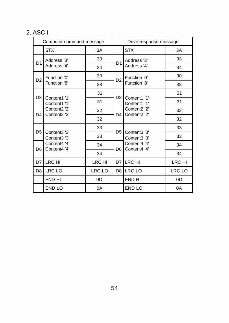
Drive response messages need to be sameas command message when do communica-tion loop detection.
Ex. Computer commands the address 52(34H) driver, data1=11, data2=22, data3=33, data4=441. RTU
53
(3) 08H : Communication loop detection
Computer command message D1 : Communication address D2 : Function code D3 : Data 1 D4 : Data 2 D5 : Data 3 D6 : Data 4 D7 : CRCL or LRC (H) D8 : CRCH or LRC (L)
(0~FFh)(08h)(0~FFh)(0~FFh)(0~FFh)(0~FFh)(0~FFh)(0~FFh)
Drive response message D1 : Communication address D2 : Function code D3 : Data 1 D4 : Data 2 D5 : Data 3 D6 : Data 4 D7 : CRCL or LRC (H) D8 : CRCH or LRC (L)
(0~FFh)(08h)(0~FFh)(0~FFh)(0~FFh)(0~FFh)(0~FFh)(0~FFh)
Computer command message Drive response message
D1 Address 34H D1 Address 34H
D2 Function code 08H D2 Function code 08H
D3 Data 1 11H D3 Data 1 11H
D4 Data 2 22H D4 Data 2 22H
D5 Data 3 33H D5 Data 3 33H
D6 Data 4 44H D6 Data 4 44H
D7 CRCL CRCL D7 CRCL CRCL
D8 CRCH CRCH D8 CRCH CRCH
2. ASCIIComputer command message Drive response message
STX 3A STX 3A
D1Address '3'Address '4'
33D1
Address '3'Address '4'
33
34 34
D2 Function '0'Function '8'
30D2 Function '0'
Function '8'
30
38 38
D3 Content1 '1'Content1 '1'Content2 '2'Content2 '2'
31D3 Content1 '1'
Content1 '1'Content2 '2'Content2 '2'
31
31 31
D432
D432
32 32
D5 Content3 '3'Content3 '3'Content4 '4'Content4 '4'
33D5 Content3 '3'
Content3 '3'Content4 '4'Content4 '4'
33
33 33
D634
D634
34 34
D7 LRC HI LRC HI D7 LRC HI LRC HI
D8 LRC LO LRC LO D8 LRC LO LRC LO
END HI 0D END HI 0D
END LO 0A END LO 0A
54

E. Communication error drive respondOnce communication error happend, drive will respond “Functioncode and 80H” and communication error code to master system.Communication error code definition
Once communication error happened, drive respond as follow1.RTU
2.ASCII
55
Error code Description
01H Function code error only (03/06/08 available)
02H Illegal data address(data address is not available)
03H Illegal data value(data value is outside limit value)
04H Illegal command, drive can't do this command
05H Check sum error
D1 D2 D3 D4 D5
Address Function code & 80H Error code CRCL CRCH
STX 3A
Address (01)30
31
Function code & 80H38
36
Error code (02)30
32
LRC (77)37
37
End code H 0D
End code L 0A

EX. In drive 01 write 1B58(7000rpm) to parameter address 04, but CD04 upper limit is 6000rpm (1770H).1.RTUComputer command message :
Drive response message :
2.ASCII
D101H
D206H
D300H
D404H
D5C3H
D650H
D7CRCL
D8CRCH
D101H
D286H
D302H
D4CRCL(C3H)
D5CRCH(A1H)
Computer command message Drive response message
STX 3A STX 3A
Address '0'Address '1'
30 Address '0'Address '1'
30
31 31
Function '0'Function '6'
30 Function '8'Function '6'
38
36 36
Address content '0'Address content '0'Address content '0'Address content '4'
30 Error code '0'Error code '2'
30
30 32
30 LRC HI '7'LRC LO '7'
37
34 37
CD04 content '1'CD04 content 'B'CD04 content '5'CD04 content '8'
31 END HI 0D
42 END LO 0A
35
38
LRC HI LRC HI
LRC LO LRC LO
END HI 0D
END LO 0A
56
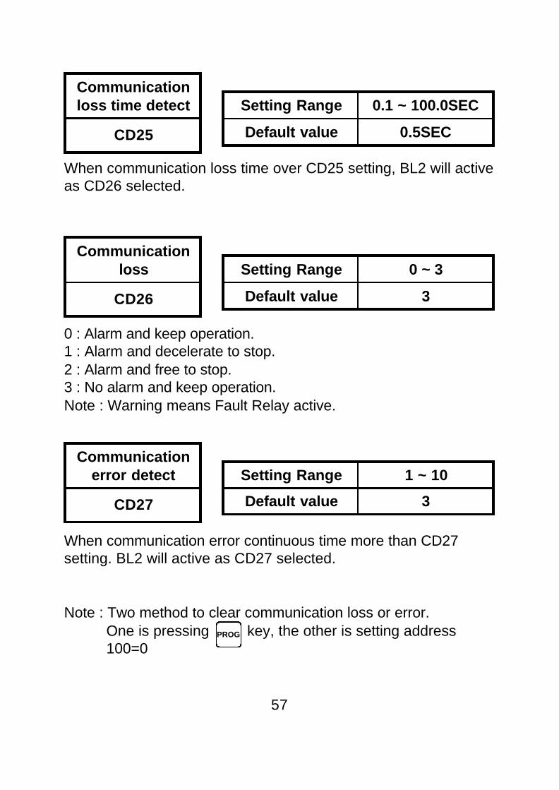
Communicationloss time detect
CD25
Setting Range 0.1 ~ 100.0SEC
Default value 0.5SEC
When communication loss time over CD25 setting, BL2 will activeas CD26 selected.
Setting Range 0 ~ 3
Default value 3
0 : Alarm and keep operation.1 : Alarm and decelerate to stop.2 : Alarm and free to stop.3 : No alarm and keep operation.Note : Warning means Fault Relay active.
Communicationerror detect
CD27
Setting Range 1 ~ 10
Default value 3
When communication error continuous time more than CD27setting. BL2 will active as CD27 selected.
Note : Two method to clear communication loss or error. One is pressing key, the other is setting address 100=0
57
Communicationloss
CD26
PROG

2nd speed indigital
CD29
58
1st speed indigital
CD28
L : 0~2000RPM.M : 0~3000RPM.H : 0~6000RPM.HX : 0~15000RPM.Note : This parameter does not work in open loop control.
Setting Range 0 or 1
Default value 0
Set address CD30=1 to reset parameters to be in default values.This parameter value will be back to 0 after reset command auto-matically.
Reset to default
CD30
L : 0~2000RPM.M : 0~3000RPM.H : 0~6000RPM.HX : 0~15000RPM.Note : This parameter does not work in open loop control.
Setting Range 0 ~ 6000RPM /0 ~ 15000RPM
Default value 1000RPM
Setting Range0 ~ 6000RPM /0 ~ 15000RPM
Default value 2000RPM

59
Communication address description
0 : Clear communication loss and communication error fault relay.1 : CW.2 : CCW.3 : Stop.Note : This is last operating command value and it is not real motor running condition.
Write speed command to address 99 in RS485 mode.
This parameter is real motor speed value. Use RS485 protocol03H to read motor speed.
RS485 speedcommand
99
RS485 operatingcommand
100
Setting Range 0 ~ 3
Motor speed(RPM)
101
Setting Range 0 ~ 6000RPM /0 ~ 15000RPM
Default value 0RPM

This real motor running condition.0 : No define1 : CW2 : CCW3 : Stop
Use RS485 protocol 03H to read error code if driver is in protec-tion mode.1 : Hardware fault or EEPROM error.2 : Motor overheat.3 : Driver over current, over voltage or over heat.4 : Driver over load.5 : Over speed.6 : Speed too low.7 : Mod Bus fail.8 : Motor lock protection.9 : Hall sensor fail.
60
Motor runningcodition
102
Error code
103

9. Trouble shootingMotors free run to stop when protect functions are effected.Disconnect power to reset the protect function.For safety , make sure all problems are solved before reconnectpower.To wait more than 5 minutes to reconnect power after disconnectpower.
61
STOP
Displaysymbol Description Check point and suggestion
Err1 EEPROM errorPress to reset alarm and set CD30=1,to reload default value to EEPROM.
Err2 Motor overheatCheck motors cooling condition.Check motors loading, motors may beoverload.
Err3 Over current
Check input voltage(over voltage).Check drives cooling condition (overheat).Check motors loading (overload).Check wire & plug between motors and drives(U,V,W shortage).Check Acc. & Dec. time setting (over current).Check CW, CCW, stop operation frequency(over current).Check inertial load, motors may get tractionfrom loading.
Err4 Over loadCheck connector if it is bad connection.Wait 5 min to restart motor.
Err5 Over speed Check loading variation if load reduces toofast.
Err6 Speed to low Check loading variation if load increases tofast.
Err8Motor lockprotection
Check rotor lock.Check load condition.
Err9 Hall sensor fail Check wire & plug between motors and drives.
Mod Bus fail
Check all drives setting are accordance.(address, communication speed, data format)Check communication wires are A to A and Bto B.

Appendix1. External braking resistor Dimension
150
130 390 10
545
395140
20.5
Part No. : E-MSAA-008000 Specification : 60 80WThe resistor value is recommended as below. The value must behigher than list value. Unit :
Evaluation of braking resistor watt
62
Ω
Ω Model No. 01 02 04 07 15 22
BL2 60 60 60 60 60 60
Model Resistor watt
AM-750~2200(H)CM-750~2200(H)
(1330/T)× (W/6000)2
AM-750~2200(M)CM-750~2200(L) (436/T)× (W/3000)2
AM-60~370(L/M/H) (220/T)× (W/6000)2
P : WattT : Deceleration timeW : Motor speedThe above caculation loading are based on 5 timesrotor interia

63
2. Hall sensor and F306 remote operator extension cable
A-0000-F306G3 F306 Remote operator
E-092A-010200 1 meter extension cable
E-092A-030200 3 meter extension cable
E-092A-050200 5 meter extension cable
E-PEAA-8P8C02 Extension connector

JUL. 2008 3st edition
ADLEEPOWER SERVICE OFFICE
R
FREQUNCY INVERTER MOTOR DRIVES
TaiwanTel No : 886-4-25622651Fax No : 886-4-25628289E-mail : [email protected] : http://www.adlee.com
Hong KongTel No : 852-24081937Fax No : 852-24071036
Guang Dong (China)Tel No : 86-757-26656498Fax No : 86-757-26658515
Wu Han (China)Tel No : 86-27-59322991Fax No : 86-27-59322992
Shanghai (China)Tel No : 86-21-64843529Fax No : 86-21-64837594
INSTRUCTION MANUAL
PART NO : E-PHAA-EBLA02
Model : BL2 series