instruction manual - puntoenergia shopmedia.puntoenergiashop.it/newmedia/downloads/regolatori/manual...
TRANSCRIPT
Tracer-BN Series
—— Maximum Power Point Tracking Solar Charge Controller
Thank you very much for selecting our product!
This manual offers important information and suggestions with respect to installation,
use and troubleshooting, etc. Please read this manual carefully before using the product
and pay attention to the safety recommendations in it.
EPSOLAR
INSTRUCTION
MANUAL
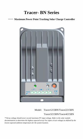
Tracer- BN Series
—— Maximum Power Point Tracking Solar Charge Controller
Model: Tracer1215BN/Tracer2215BN
Tracer3215BN/Tracer4215BN
**Array voltage should never exceed maximum PV input voltage. Refer to the solar module
documentation to determine the highest expected array Voc (open circuit voltage) as defined by the
lowest expected ambient temperature for the system location.

Contents
1 Important Safety Information .................................................................................... 1
2 General Information.................................................................................................. 2
2.1 Overview ....................................................................................................... 2
2.2 Optional Accessories ...................................................................................... 4
3 Installation Instructions............................................................................................. 5
3.1 General Installation Notes .............................................................................. 5
3.2 Mounting ....................................................................................................... 6
4 Operation .................................................................................................................. 7
4.1 MPPT Technology ......................................................................................... 7
4.2 Battery Charging Information ........................................................................ 8
4.3 LED Indications ........................................................................................... 11
4.4 Setting Operation ......................................................................................... 12
5 Protections, Troubleshooting and Maintenance ....................................................... 14
5.1 Protection ..................................................................................................... 14
5.2 Troubleshooting ........................................................................................... 15
5.3 Maintenance ................................................................................................. 16
6 Warranty ................................................................................................................. 17
7 Technical Specifications ......................................................................................... 18
1
1 Important Safety Information
Save These Instructions
This manual contains important safety, installation and operating instructions for
Tracer-BN Series controller.
The following symbols are used throughout this manual to indicate potentially
dangerous conditions or mark important safety instructions. Please take care when
meeting these symbols.
WARNING: Indicates a potentially dangerous condition.
Use extreme caution when performing this task.
CAUTION: Indicates a critical procedure for safe and proper
operation of the controller.
NOTE: Indicates a procedure or function that is important for
the safe and proper operation of the controller.
General Safety Information
·Read all of the instructions and cautions in the manual before beginning installation.
·There are no user serviceable parts inside the Tracer-BN series. Do not disassemble or
attempt to repair the controller.
·Disconnect the solar module and fuse/breakers near to battery before installing or
adjusting the Tracer-BN series.
·Install external fuses/breakers as required.
·Do not allow water to enter the controller.
·Confirm that power connections are tightened to avoid excessive heating from loose
connection.

2
2 General Information
2.1 Overview
Thank you for selecting the Tracer-BN series controller which represents advanced
technology of our company. The features are listed below:
·12V/24V automatic identify or user-defined working voltage.
·Excellent heat dissipation. Using the integration of cast aluminum radiator shell, the
controller can be natural cooling.
·Advanced maximum power point tracking technology to optimize using the solar
system. Peak conversion efficiency is as high as 98%.
·Lock the MP point fast and the controller provides the industry’s highest tracking
efficiency of 99%.
·Widely used, automatic recognize day or night.
·Several load methods are supported to convenient for different demand.
·Support 4 charging options: Sealed, Gel, Flooded and User-defined.
·Adopting temperature compensation and correcting the charging and discharging
parameters automatically, improving the battery lifetime.
·Protection: over temperature, over charging, PV and load short, PV (battery) revered,
over current protection.
·Actual power convenient and record function makes convenience to check the datum
every day, every month and every year.
·RS-485 ports via the open standard Modbus protocol are supported to meet different
occasion of demand.
·With supporting PC monitoring software and remote meter MT50, it is convenient to
check the real-time data of controllers and set the parameters.
·Support firmware update.
The Tracer-BN series controller is for off-grid solar system and control the charging and
discharging of the battery. The controller features a smart tracking algorithm that
maximizes the energy from the solar PV module(s) and charge the battery. At the same
time, the low voltage disconnect function (LVD) will prevent the battery from over
discharging.
The battery charging process has been optimized for long battery life and improved
system performance. The comprehensive self-diagnostics and electronic protection
functions can prevent damage from installation mistakes or system faults. In addition,
the Tracer-BN series controller has a RJ45 interface to allow communication with other
accessory.
Although the Tracer-BN series controller is very simple to configure and use, please
take your time to read the operator's manual and become familiar with the controller.
This will help you make full use of all the functions and improve your solar PV system.

3
Figure 2-1 Tracer-BN Series Characteristics
1 – Heat Sink
Cast aluminum heat sink to dissipate controller heat.
2 – Charging LED Indicator
Indicate that the battery is charging or not.

4
3 – Battery LED Indicator
Show charging status.
4 – Key
Switch the load on/off in the manual mode and clear the part of faults.
5 –Temperature Sensor Port
Connect remote temperature sensor to measure ambient temperature and make
temperature compensation for charging and discharging.
6 – Solar Module Terminals
Connect solar modules.
7 – Battery Terminals
Connect batteries.
8 – Load Terminals
Connect loads.
9 – RS-485 Port (RJ45 interface)
Connect with PC or MT50 to monitor or update firmware.
2.2 Optional Accessories
1. Remote Temperature Sensor (Model:RTS300R47K3.81A)
Acquiring of battery temperature for undertaking temperature compensation of control
parameters, the standard length of the cable is 3m (length can be customized). The
RTS300R47K3.81A connects to the port (5th ) on the controller.
Note: unplug the RTS, the temperature of battery will be set to a fixed value 25 ºC.
2. Remote Meter (Model:MT50)
The digital remote meter displays system operating information, error indications, and
self-diagnostics. Information displayed on a backlit LCD display is easy to read and
large buttons make navigating the meter menus easy. The meter can be flush mounted in
a wall or frame. The MT50 (standard edition) is supplied with one 2 meter long cable.
The MT50 connects the Tracer-BN series with the RJ45 interface.
3. Super Parameter Programmer (Model: SPP-01)
The SPP-01 can realize one-key setting operation which is suitable for bulk quantity
products setting in the projects.
4. USB To RS-485 converter (Model:CC-USB-RS485-150U)
USB To RS-485 converter is used to monitor each controller on the network using
EPsolar Station PC software and update the firmware. The length of cable is 1.5m. The
CC-USB-RS485-150U connects to theRS-485 Port (9th) on the controller.
5
3 Installation Instructions
3.1 General Installation Notes
Be very careful when working with batteries. Wear eye protection. Have fresh water
available to wash and clean any contact with battery acid.
Uses insulated tools and avoid placing metal objects near the batteries.
Explosive battery gasses may be present during charging. Be certain there is
sufficient ventilation.
Loose power connections and/or corroded wires may result in resistive connections
that melt wire insulation, burn surrounding materials, or even cause fire. Ensure tight
connections and use cable clamps to secure cables and prevent them from swaying in
mobile applications.
Use with Sealed batteries only under the controller requires.
Battery connection may be wired to one battery or a bank of batteries. The following
instructions refer to a singular battery, but it is implied that the battery connection can
be made to either one battery or a group of batteries in a battery bank.
Select the system cables according to 3A/mm2 current density.
6
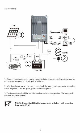
3.2 Mounting
1. Connect components to the charge controller in the sequence as shown above and pay
much attention to the ―+‖ (Red) and ―-‖ (Black).
2. After installation, power the battery and check the battery indicator on the controller,
it will be green. If it’s not green, please refer to chapter 5.
3. The battery fuse should be installed as close to battery as possible. The suggested
distance is within 150mm.
NOTE: Unplug the RTS, the temperature of battery will be set to a
fixed value 25 ºC.

7
4 Operation
4.1 MPPT Technology
The Tracer-BN series utilizes Maximum Power Point Tracking technology to extract
maximum power from the solar module (s). The tracking algorithm is fully automatic
and does not require user adjustment, Tracer-BN series technology will track the array
maximum power point voltage (Vmp) as it varies with weather conditions, ensuring that
maximum power is harvested from the array through the course of the day.
· Current Boost
In many cases, Tracer-BN series MPPT technology will ―boost‖ the solar charge current.
For example, a system may have 8 Amps of solar current flowing into the Tracer-BN
series and 10 Amps of charge current flowing out to the battery. The Tracer-BN series
does not create current! Rest assured that the power into the Tracer-BN series is the
same as the power out of the Tracer-BN series. Since power is the product of voltage
and current (Volts×Amps), the following is true*:
(1) Power Into the Tracer-BN series =Power Out of the Tracer-BN series
(2) Volts In×Amps In=Volts Out×Amps Out
* Assuming 100% efficiency. Actually, the losses in wiring and conversion exist.
If the solar module’s Vmp is greater than the battery voltage, it follows that the battery
current must be proportionally greater than the solar input current so that input and
output power are balanced. The greater the difference between the maximum power
voltage and battery voltage, the greater the current boost. Current boost can be
substantial in systems where the solar array is of a higher nominal voltage than the
battery.
· An Advantage Over Traditional Controllers
Traditional controllers connect the solar module directly to the battery when
recharging. This requires that the solar module operate in a voltage range that is below
the module’s Vmp. In a 12V system for example, the battery voltage may range from
11-15Vdc but the module’s Vmp is typically around 16 or 17V.
Figure 4-1 shows a typical current VS. voltage output curve for a nominal 12V
off-grid module.
8
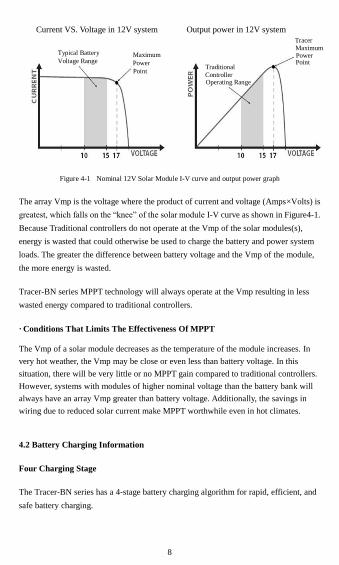
Current VS. Voltage in 12V system Output power in 12V system
Figure 4-1 Nominal 12V Solar Module I-V curve and output power graph
The array Vmp is the voltage where the product of current and voltage (Amps×Volts) is
greatest, which falls on the ―knee‖ of the solar module I-V curve as shown in Figure4-1.
Because Traditional controllers do not operate at the Vmp of the solar modules(s),
energy is wasted that could otherwise be used to charge the battery and power system
loads. The greater the difference between battery voltage and the Vmp of the module,
the more energy is wasted.
Tracer-BN series MPPT technology will always operate at the Vmp resulting in less
wasted energy compared to traditional controllers.
· Conditions That Limits The Effectiveness Of MPPT
The Vmp of a solar module decreases as the temperature of the module increases. In
very hot weather, the Vmp may be close or even less than battery voltage. In this
situation, there will be very little or no MPPT gain compared to traditional controllers.
However, systems with modules of higher nominal voltage than the battery bank will
always have an array Vmp greater than battery voltage. Additionally, the savings in
wiring due to reduced solar current make MPPT worthwhile even in hot climates.
4.2 Battery Charging Information
Four Charging Stage
The Tracer-BN series has a 4-stage battery charging algorithm for rapid, efficient, and
safe battery charging.
Typical Battery
Voltage Range
Point
Power
Traditional
Maximum
Operating Range Controller
Tracer
Point Power Maximum

9
Figure 4-2 Tracer-BN series MPPT charging algorithm
·Bulk Charge
In this stage, the battery voltage has not yet reached boost voltage and 100% of available
solar power is used to recharge the battery.
·Boost Charge
When the battery has recharged to the Boost voltage setpoint, constant-voltage
regulation is used to prevent heating and excessive battery gassing. The Boost stage
remains 120 minutes and then goes to Float Charge. Every time when the controller is
powered on, if it detects neither over discharged nor overvoltage, the charging will
enter into boost charging stage.
·Float Charge
After the Boost voltage stage, Tracer-BN series will reduce the battery voltage to Float
voltage setpoint. When the battery is fully recharged, there will be no more chemical
reactions and all the charge current transmits into heat and gas at this time. Then the
Tracer-BN series reduces the voltage to the floating stage, charging with a smaller
voltage and current. It will reduce the temperature of battery and prevent the gassing,
also charging the battery slightly at the same time. The purpose of Float stage is to offset
the power consumption caused by self consumption and small loads in the whole system,
while maintaining full battery storage capacity.
In Float stage, loads can continue to draw power from the battery. In the event that the
system load(s) exceed the solar charge current, the controller will no longer be able to

10
maintain the battery at the Float setpoint. Should the battery voltage remains below the
boost reconnect charging voltage, the controller will exit Float stage and return to
Bulk charging.
·Equalize
WARNING: Risk of explosion!
Equalizing flooded battery can produce explosive gases, so well
ventilation of battery box is necessary.
CAUTION: Equipment damage!
Equalization may increase battery voltage to the level
damaging to sensitive DC loads. Ensure that all load allowable
input voltages are greater than the equalizing charging set
point voltage.
CAUTION: Equipment damage! Over-charging and excessive
gas precipitation may damage the battery plates and activate
material shedding on them. Too high an equalizing charge or
for too long may cause damage. Please carefully review the
specific requirements of the battery used in the system.
Certain types of batteries benefit from periodic equalizing charge, which can stir the
electrolyte, balance battery voltage and complete chemical reaction. Equalizing charge
increases the battery voltage, higher than the standard complement voltage, which
gasifies the battery electrolyte.
If it detects that the battery is being over discharged, the solar controller will
automatically turn the battery to equalization charging stage, and the equalization
charging will be 120mins. Equalizing charge and boost charge are not carried out
constantly in a full charge process to avoid too much gas precipitation or overheating of
battery.
11
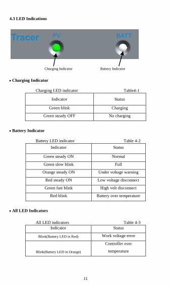
4.3 LED Indications
Charging Indicator Battery Indicator
Charging Indicator
Charging LED indicator Table4-1
Indicator Status
Green blink Charging
Green steady OFF No charging
Battery Indicator
Battery LED indicator Table 4-2
Indicator Status
Green steady ON Normal
Green slow blink Full
Orange steady ON Under voltage warning
Red steady ON Low voltage disconnect
Green fast blink High volt disconnect
Red blink Battery over temperature
All LED Indicators
All LED indicators Table 4-3
Indicator Status
Blink(Battery LED in Red) Work voltage error
Blink(Battery LED in Orange)
Controller over
temperature

12
4.4 Setting Operation
Three methods to configure the controller:
1–Remote meter, MT50/MT100 (Use standard twisted net cable, model:
CC-RS485-RS485-200U-MT).
2–Super parameter programmer, SPP-01(Use standard twisted net cable, model:
CC-RS485-RS485-200U). One-key easily configure and apply to batch setting.
3–PC monitoring setting software ―Solar Station Monitor‖(Use USB to RS485
converter cable with model: CC-USB-RS485-150U.

13
WARNING: Do not use the standard twisted-net cable to
connect the device and PC net interface, or the permanent
damage will occur.
•Load Set Mode
1.Manual Control (default)
2.Light ON/Off
3.Light ON+ Timer
4.Time Control
•Battery Type
1.Gel 2.Sealed(default) 3.Flooded 4.User
NOTE: Please refer to user guide or contact with the sales for the
detail of setting operation.
14
5 Protections, Troubleshooting and Maintenance
5.1 Protection
·PV Array Short Circuit
When PV short circuit occurs, the controller will stop charging. Clear it to resume
normal operation.
·PV Overvoltage
If PV voltage is larger than maximum input open voltage 150V, PV will remain
disconnected and warning until the voltage falls safely below 145V. PV voltage cannot
be too high, otherwise it may damage the controller, please verify the PV parameter.
·PV Overcurrent
The Tracer-BN series controller will limit battery charging current to the Maximum
Battery Current rating. Therefore an over-sized solar array will not operate at peak
power.
·Load Overload
If the load current exceeds the maximum load current rating 1.05 times, the controller
will disconnect the load. Overloading must be cleared up through reducing the load
and restarting controller.
·Load Short Circuit
Fully protected against load wiring short-circuit. Once the load short (more than
quadruple rate current), the load short protection will start automatically. After five
automatic load reconnect attempts, the fault must be cleared by restarting controller.
·PV Reverse Polarity
Fully protection against PV reverse polarity, no damage to the controller will result.
Correct the miswire to resume normal operation.
·Battery Reverse Polarity
Fully protection against battery reverse polarity, no damage to the controller will result.
Correct the miswire to resume normal operation.
·Damaged Remote Temperature Sensor
If the temperature sensor short-circuited or damaged, the controller will be charging or

15
discharging at the default temperature 25℃ to prevent the battery damaged from
overcharging or over discharged.
·Over Temperature Protection
If the temperature of the controller heat sinks exceeds 85℃, the controller will
automatically start the overheating protection and recover below 75℃.
5.2 Troubleshooting
Trouble Shooting Table 5-1
Faults Possible reasons Troubleshooting
Charging LED indicator
off during daytime when
sunshine falls on PV
modules properly
PV array
disconnection
Confirm that PV and battery wire
connections are correct and tight.
Battery LED indicator
green fast blink
Battery voltage
higher than over
voltage disconnect
voltage(OVD)
Check if battery voltage too high,
and disconnect the solar module.
Battery LED indicator is
orange
Battery under
voltage
Load output is normal, charging
LED indicator will return to
green automatically when fully
charged.
Battery LED indicator
red color
Battery low voltage
disconnect
The controller cut off the output
automatically, LED indicator
will return to green automatically
when fully charged.
All the LED indicators
blink.
(battery orange indicator
blink)
Too high
temperature of
controller
When heat sink of the controller
exceeds 85℃, the controller will
automatically cut input and
output circuit. When the
temperature below 75℃, the
controller will resume to work.
All the LED indicators
blink.
(battery red indicator
blink)
System voltage
error
Check whether the battery
voltage match with the controller
working voltage. Please change
to a suitable battery or reset the
working voltage. Remove all
faults and click the button to
resume to work.
No output load terminals Over load or Short
circuit
Remove or reducing the load and
click the button, the controller
will resume to work after 3
seconds.

16
NOTE: If all the led are off, please check the voltage of battery. At least 9V
voltage to activate the controller.
NOTE: If the charging led is steady off without miswire, check the PV input
voltage which should be higher than battery’s.
5.3 Maintenance
The following inspections and maintenance tasks are recommended at least two times
per year for best performance.
Check that the controller is securely mounted in a clean and dry environment.
Check that the air flow and ventilation around the controller is not blocked. Clear all
dirt or fragments on the heat sink.
Check all the naked wires to make sure insulation is not damaged for serious
solarization, frictional wear, dryness, insects or rats etc. Maintain or replace the wires
if necessary.
Tighten all the terminals. Inspect for loose, broken, or burnt wire connections.
Confirm that all the system components are ground connected tightly and correctly.
Confirm that all the terminals have no corrosion, insulation damaged, high
temperature or burnt/discolored sign, tighten terminal screws to the suggested torque.
Inspect for dirt, insects and corrosion, and clear up.
Check and confirm that lightning arrester is in good condition. Replace a new one in
time to avoid damaging of the controller and even other equipments.
CAUTION:Risk of electric shock!
Make sure all the power is turned off before above operations, and
then follow the corresponding inspections and operations.
17
6 Warranty
The Tracer-BN Series charge controller is warranted to be free from defects for a
period of TWO (2) years from the date of shipment to the original end user.
• Claim Procedure:
Before requesting warranty service, check the Operation Manual to be certain that
there is a problem with the controller. Return the defective product to us with shipping
charges prepaid if problem cannot be solved. Provide proof of date and place of
purchase. To obtain rapid service under this warranty, the returned products must
include the model, serial number and detailed reason for the failure, the module type
and size, type of batteries and system loads. This information is critical to a rapid
disposition of your warranty claim.
•This Warranty Does Not Apply Under The Following Conditions:
1. Damage by accident, negligence, abuse or improper use.
2. PV or load current exceeding the ratings of product.
3. Unauthorized product modification or attempted repair.
4. Damaged occurring during shipment.
5. Damage results from acts of nature such as lightning, weather extremes.
6. Irreclaimable mechanical damage.

18
7 Technical Specifications
• Electrical Parameters Table 7-1
Description Parameter
Nominal system voltage 12VDC / 24VDC Auto work
Rated charge current
Tracer1215BN 10A
Tracer2215BN 20A
Tracer3215BN 30A
Tracer4215BN 40A
Rated discharge current
Tracer1215BN 10A
Tracer2215BN 20A
Tracer3215BN 20A
Tracer4215BN 20A
Maximum battery voltage 32V
Max. solar input voltage 150VDC
Max. PV input power
Tracer1215BN 130W(12V) 260W(24V)
Tracer2215BN 260W(12V) 520W(24V)
Tracer3215BN 390W(12V) 780W(24V)
Tracer4215BN 520W(12V) 1040W(24V)
Self-consumption* ≤50mA(12V) ≤27mA(24V)
Charge circuit voltage drop ≤0.26V
Discharge circuit voltage drop ≤0.15V
Temperature compensate
coefficient -3mV/ºC/2V(default)
Communication RS485(RJ45 interface)
Battery Voltage Parameters (parameters is in 12V system at 25℃, please use
double value in 24V.)

19
• Control Parameters Table 7-2
Battery charging setting Gel Sealed Flooded User
Over Voltage Disconnect
Voltage 16.0V 16.0V 16.0V 9~17V
Charging Limit Voltage 15.0V 15.0V 15.0V 9~17V
Over Voltage Reconnect
Voltage 15.0V 15.0V 15.0V 9~17V
Equalize Charging Voltage —— 14.6V 14.8V 9~17V
Boost Charging Voltage 14.2V 14.4V 14.6V 9~17V
Float Charging Voltage 13.8V 13.8V 13.8V 9~17V
Boost Reconnect Charging
Voltage 13.2V 13.2V 13.2V 9~17V
Low Voltage Reconnect
Voltage 12.6V 12.6V 12.6V 9~17V
Under Voltage Warning
Reconnect Voltage 12.2V 12.2V 12.2V 9~17V
Under Volt. Warning Volt. 12.0V 12.0V 12.0V 9~17V
Low Volt. Disconnect Volt. 11.1V 11.1V 11.1V 9~17V
Discharging Limit Voltage 10.6V 10.6V 10.6V 9~17V
Equalize Duration —— 2 hrs. 2 hrs. 0~3 hrs.
Boost Duration 2 hrs. 2 hrs. 2 hrs. 0~3 hrs.
Notes: User type is the user defined battery type. The default value is the same as
sealed type. When modify it, please follow the below logistic relation:
a ) Over Voltage Disconnect Voltage > Charging Limit Voltage ≥ Equalize Charging
Voltage ≥ Boost Charging Voltage ≥ Float Charging Voltage > Boost Reconnect
Charging Voltage.
b ) Over Voltage Disconnect Voltage > Over Voltage Reconnect Voltage
c) Low Voltage Reconnect Voltage > Low Voltage Disconnect Voltage ≥ Discharging
Limit Voltage.
d ) Under Voltage Warning Reconnect Voltage > Under Voltage Warning Voltage ≥
Discharging Limit Voltage.
e ) Boost Reconnect Charging voltage > Low Voltage Disconnect Voltage.

20
• Environmental Parameters Table 7-3
Environmental Parameter
Ambient temperature
range -35℃to +55℃
Storage temperature
range -35℃ to +80℃
Humidity range ≤95%(NC)
Enclosure IP30
Altitude ≤3000 m
• Mechanical Parameters (Tracer1215BN) Table 7-4
Mechanical Parameter
Dimension 196mm x 117.8mm x 36mm
Mounting dimension Detail in dimensions drawing
Mounting hole size Φ4.7
Power cable 4mm2
Weight 0.9kg
• Mechanical Parameters (Tracer2215BN) Table 7-5
Mechanical Parameter
Dimension 216.6mm x 142.6mm x 56mm
Mounting dimension Detail in dimensions drawing
Mounting hole size Φ4.7
Power cable 10mm2
Weight 1.5kg
21
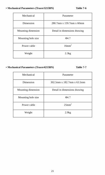
• Mechanical Parameters (Tracer3215BN) Table 7-6
Mechanical Parameter
Dimension 280.7mm x 159.7mm x 60mm
Mounting dimension Detail in dimensions drawing
Mounting hole size Φ4.7
Power cable 16mm2
Weight 2.3kg
• Mechanical Parameters (Tracer4215BN) Table 7-7
Mechanical Parameter
Dimension 302.5mm x 182.7mm x 63.5mm
Mounting dimension Detail in dimensions drawing
Mounting hole size Φ4.7
Power cable 25mm2
Weight 2.9kg

PV Power — Conversion Efficiency Curve
Tracer1215BN Illumination Intensity: 1000W/m2
Temp: 25ºC
1. Solar Module MPP Voltage(16.5V, 34V, 66V) / Nominal System Voltage(12V)
2. Solar Module MPP Voltage(34V, 66V, 98V) / Nominal System Voltage(24V)
0 50 100 150 200 250 30086
88
90
92
94
96
98
100
Charging Power(W)
Co
nve
rsio
n E
ffic
ien
cy(%
)
24V Conversion Efficiency Curves
98V
66V
34V

Tracer2215BN Illumination Intensity: 1000W/ m2 Temp: 25ºC
1. Solar Module MPP Voltage(16.5V, 33V, 66V) / Nominal System Voltage(12V)
2. Solar Module MPP Voltage(33V, 66V, 98V) / Nominal System Voltage(24V)
50 100 150 200 250 300 350 400 450 500 55092
93
94
95
96
97
98
99
Charging Power(W)
Co
nve
rsio
n E
ffic
ien
cy(%
)
24V Conversion Efficiency Curves
98V
66V
33V

Tracer3215BN Illumination Intensity: 1000W/ m2 Temp: 25ºC
1. Solar Module MPP Voltage(16.5V, 33V, 66V) / Nominal System Voltage(12V)
2. Solar Module MPP Voltage(33V, 66V, 98V) / Nominal System Voltage(24V)
0 50 100 150 200 250 300 350 40091
92
93
94
95
96
97
98
Charging Power(W)
Co
nve
rsio
n E
ffic
ien
cy(%
)
12V Conversion Efficiency Curves
16.5V
33V
66V
0 100 200 300 400 500 600 700 80088
90
92
94
96
98
10024V Conversion Efficiency Curves
Charging Power(W)
Co
nve
rsio
n E
ffic
ien
cy(%
)
33V
66V
98V

Tracer4215BN Illumination Intensity: 1000W/ m2 Temp: 25ºC
1. Solar Module MPP Voltage(16.5V, 33V, 66V) / Nominal System Voltage(12V)
2. Solar Module MPP Voltage(33V, 66V, 98V) / Nominal System Voltage(24V)

Tracer1215BN Dimensions (mm)

Tracer2215BN Dimensions (mm)

Tracer3215BN Dimensions (mm)

Tracer4215BN Dimensions (mm)


Version number: V1.7

BEIJING EPSOLAR TECHNOLOGY CO., LTD.
Tel: +86-10-82894112 / 82894962
Fax: +86-10-82894882
E-mail: [email protected]
Website: http://www.epsolarpv.com/