instruction manual - magtrol.com name date signature written by / modified by pm ... • for use...
TRANSCRIPT

ISSUE 0 i
P/N 633.018 E
( MALMU116-02/E )
INSTRUCTION MANUAL
LOAD MONITORING UNIT
LMU 116 VERSIONS 02X AND 02XC

LOAD MONITORING UNITLMU 116 VERSIONS 02x AND 02xC
ii ISSUE 0 INSTRUCTION MANUAL P/N 633.018 E
REVISION RECORD SHEET
Issue Date Description
Master copy stored at : IC
Original issueapproved by
Department Name Date Signature
Written by /Modified by
PMNo.
(ProductManager)
Signature
Development / ID J. Perriard
Product Manager / IC J. M. Garcia
0 21.12.98 S. Chatton - Preliminary issue (for approval) - - -
LOAD MONITORING UNITLMU 116 VERSIONS 02x AND 02xC
INSTRUCTION MANUAL P/N 633.018 E ISSUE 0 iii
Copyright © Vibro-Meter SA, 1998
All rights reserved
Published and printed by Vibro-Meter SA in Fribourg, Switzerland
The information contained in this document is subject to change without notice. This information shall not be used,duplicated or disclosed, in whole or in part, without the express written permission of Vibro-Meter.

LOAD MONITORING UNITLMU 116 VERSIONS 02x AND 02xC
iv ISSUE 0 INSTRUCTION MANUAL P/N 633.018 E
THIS PAGE INTENTIONALLY LEFT BLANK
LOAD MONITORING UNIT TABLE OF CONTENTSLMU 116 VERSIONS 02x AND 02xC
INSTRUCTION MANUAL P/N 633.018 E ISSUE 0 v
PREFACE VII
Purpose and Scope of This Manual vii
Who Should Use This Manual ? vii
Manual Organization viii
Related Publications viii
1 SAFETY 1-1
1.1 Symbols Used in This Manual 1-1
1.2 Important Remarks on Safety 1-21.2.1 Location of Safety Symbols in This Manual 1-2
1.3 Additional Remarks on Safety 1-3
2 INTRODUCTION 2-1
3 CONFIGURATION AND CALIBRATION 3-1
3.1 Configuration of the Load Monitoring Unit 3-23.1.1 Adaptation of the Monitor to the Supply Voltage 3-23.1.2 Selection of the Type of Wiring to the Strain Gauge 3-33.1.3 Designation of the Voltage and Current Inputs/Outputs 3-33.1.4 Configuration of the Detection Chains 3-43.1.5 Selection of the Pass Band 3-113.1.6 Selection of the Sensitivity Range 3-123.1.7 Combination of Signals on the Summing Circuit 3-123.1.8 Selecting the X-Coefficient Range 3-13
3.2 Calibration of the Load Monitoring Unit 3-143.2.1 Zero Adjustment on the Voltage Output 3-143.2.2 Zero Adjustment on the Current Output 3-143.2.3 Sensitivity Adjustment on the Voltage Output 3-143.2.4 Sensitivity Adjustment on the Current Output 3-153.2.5 Adjustment of the Ulevel1 and Ulevel2 Detection Thresholds 3-153.2.6 Adjustment of the Ulevel3 and Ulevel4 Detection Thresholds 3-17
TABLE OF CONTENTS
COVER PAGE I
REVISION RECORD SHEET II
COPYRIGHT III
TABLE OF CONTENTS V

TABLE OF CONTENTS LOAD MONITORING UNITLMU 116 VERSIONS 02x AND 02xC
vi ISSUE 0 INSTRUCTION MANUAL P/N 633.018 E
3.2.7 Adjustment of the X-Coefficient (Summing Circuit) 3-18
3.3 Configuration of the taring circuitry 3-193.3.1 Add the TARE 3-193.3.2 Remove the TARE 3-193.3.3 Selection of the TARE signal 3-193.3.4 Connection diagram of the taring control circuitry 3-20
3.4 Customized Configuration 3-20
4 ASSEMBLY AND CONNECTION 4-1
4.1 General 4-1
4.2 Assembly of the Load Monitoring Unit 4-2
4.3 Connection of the Load Monitoring Unit 4-4
5 APPLICATIONS 5-1
5.1 Simple Weighing System with Adjustable Tare 5-1
5.2 Multi-Transducer Weighing System for Container Loading Bridges 5-6
A MECHANICAL DRAWING A-1
B CONFIGURATION AND CALIBRATION FORM B-1
C DECLARATION OF EC CONFORMITY C-1
PRODUCT DEFECT REPORT
DOCUMENTATION EVALUATION FORM

LOAD MONITORING UNIT PREFACELMU 116 VERSIONS 02x AND 02xC
INSTRUCTION MANUAL P/N 633.018 E ISSUE 0 vii
PREFACE
Purpose and Scope of This Manual
This manual has all the necessary information regarding the installation, configuration, calibrationand connection of the LMU 116 load monitoring unit for strain gauge transducers.
Who Should Use This Manual ?
This manual is for users who want to install the load monitoring unit on lifting, weighing or otherequipment, to program it, calibrate it, connect it to the strain gauge and to a display and alarmsystem and to use it to measure loads.
The user should have suitable technical training in mechanics and electronics (certificate ofprofessional ability or equivalent) so as to allow him to install and use this load monitoring unit.
PREFACE LOAD MONITORING UNITLMU 116 VERSIONS 02x AND 02xC
viii ISSUE 0 INSTRUCTION MANUAL P/N 633.018 E
Manual Organization
This section gives an overview of the structure of the manual and the information contained withinit. Some information has been deliberately repeated in different sections of the document to minimizecross-referencing and to facilitate understanding through reiteration.
The chapters of this manual are presented in a logical order. You should read those that are mostrelevant to you and then keep the manual at hand for future reference.
The structure of the manual is as follows :
Chapter 1 : Safety - Contains important information for your personal safety and the correctinstallation of the load monitoring unit.
THIS CHAPTER SHOULD BE READ BEFORE STARTING INSTALLATION,CONFIGURATION, CALIBRATION AND CONNECTION OF THE LOADMONITORING UNIT.
Chapter 2 : Introduction - Contains the technical data sheet for the load monitoring unit.This data sheet describes the monitor and gives its technical characteristics.
Chapter 3 : Configuration and Calibration - Description of the programming and calibrationprocedures for optimum functioning of the load monitoring unit.
Chapter 4 : Assembly and Connection - Specifications for the assembly and connectionof the load monitoring unit to a strain gauge and a display and alarm system.
Chapter 5 : Applications - Examples of applications for the load monitoring unit.
Appendix A : Mechanical Layout - Drawing of the LMU 116 load monitoring unit.
Appendix B : Configuration and Calibration Form - Contains a blank form which can becopied and filled in during the configuration and calibration of the load monitoringunit.
Appendix C : CE Conformity declaration - Document certifying that the LMU 116 loadmonitoring unit conform to the EN-50081-2 and EN-50082-2 standards.
Product Defect Report - Allows the user to indicate problems observed on amodule/system, thus enabling our After-Sales Service department to repair theunit as quickly as possible.
Documentation Evaluation Form - Allows the user to provide us with valuablefeedback on our documentation.
Related Publications
For additional information relating to the use of the LMU 116 load monitoring unit, the operator isreferred to the following document :
• LB 210 & LB 230 Instruction manual P/N 632.005

LOAD MONITORING UNIT SAFETYLMU 116 VERSIONS 02x AND 02xC
INSTRUCTION MANUAL P/N 633.018 E ISSUE 0 1-1
1 SAFETY
1.1 Symbols Used in This Manual
The following symbols and type styles may be used in this manual to highlight certain parts of thetext :
The NOTE symbol.
This is intended to draw the operator’s attention to complementary information oradvice relating to the subject being treated.It introduces information enabling the correct and optimal functioning of the product tobe obtained.
The CAUTION safety symbol.
This is used to draw the operator ’s attention to information, directives,procedures, etc. which, if ignored, may result in damage being caused to thematerial being used.The associated text describes the necessary precautions to take and theconsequences that may arise if the precautions are ignored.
THE WARNING SAFETY SYMBOL.
THIS INTRODUCES DIRECTIVES, PROCEDURES, PRECAUTIONARYMEASURES, ETC. WHICH MUST BE EXECUTED OR FOLLOWED WITH UTMOSTCARE AND ATTENTION, OTHERWISE THE PERSONAL SAFETY OF THEOPERATOR OR THIRD PARTIES MAY BE PUT AT RISK.THE READER MUST ABSOLUTELY TAKE NOTE OF THE ACCOMPANYING TEXT,AND ACT UPON IT, BEFORE PROCEEDING FURTHER.
SAFETY LOAD MONITORING UNITLMU 116 VERSIONS 02x AND 02xC
1-2 ISSUE 0 INSTRUCTION MANUAL P/N 633.018 E
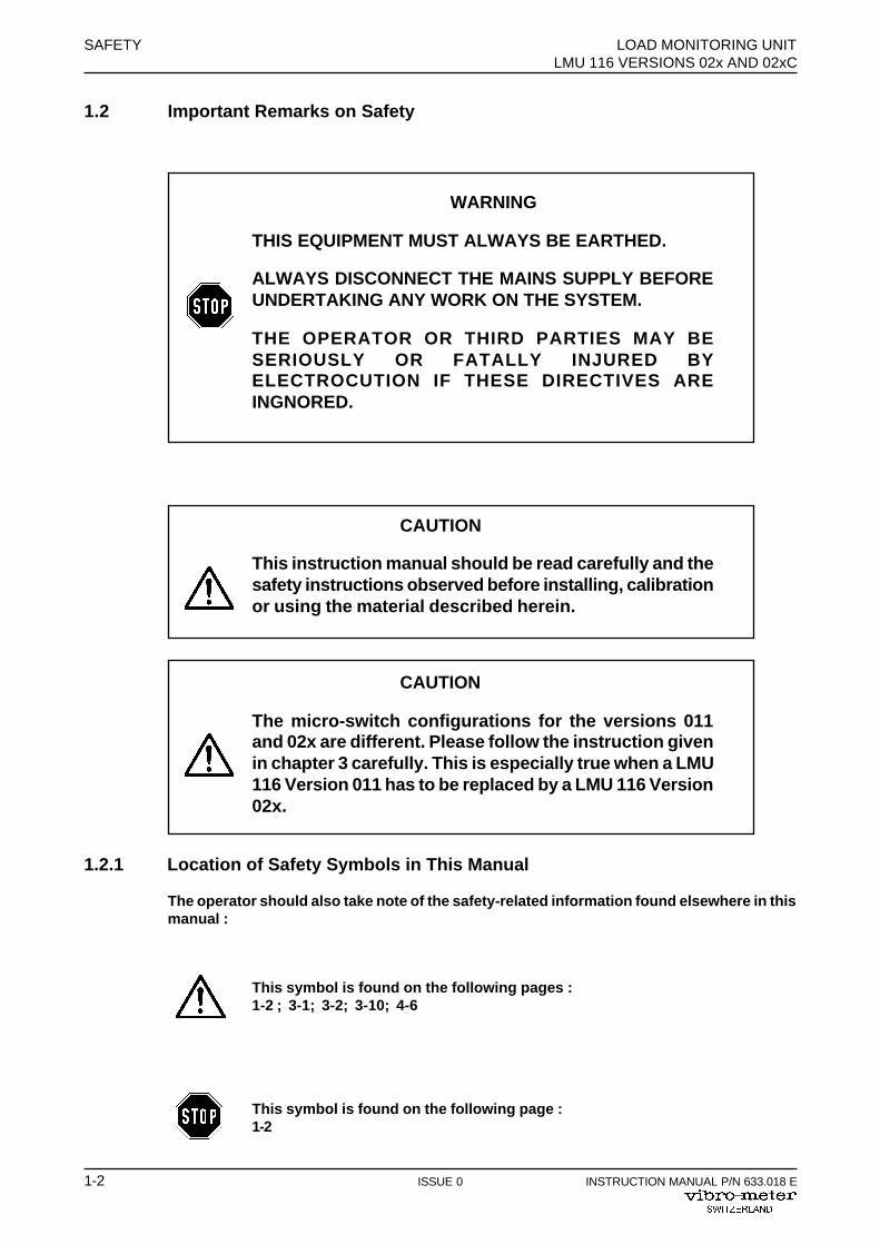
1.2 Important Remarks on Safety
WARNING
THIS EQUIPMENT MUST ALWAYS BE EARTHED.
ALWAYS DISCONNECT THE MAINS SUPPLY BEFOREUNDERTAKING ANY WORK ON THE SYSTEM.
THE OPERATOR OR THIRD PARTIES MAY BESERIOUSLY OR FATALLY INJURED BYELECTROCUTION IF THESE DIRECTIVES AREINGNORED.
CAUTION
This instruction manual should be read carefully and thesafety instructions observed before installing, calibrationor using the material described herein.
CAUTION
The micro-switch configurations for the versions 011and 02x are different. Please follow the instruction givenin chapter 3 carefully. This is especially true when a LMU116 Version 011 has to be replaced by a LMU 116 Version02x.
1.2.1 Location of Safety Symbols in This Manual
The operator should also take note of the safety-related information found elsewhere in thismanual :
This symbol is found on the following pages :1-2 ; 3-1; 3-2; 3-10; 4-6
This symbol is found on the following page :1-2
LOAD MONITORING UNIT SAFETYLMU 116 VERSIONS 02x AND 02xC
INSTRUCTION MANUAL P/N 633.018 E ISSUE 0 1-3
1.3 Additional Remarks on Safety
For the correct and safe use of this instrument, it is essential that both operating andservicing personnel follow generally accepted safety procedures in addition to safetyprecautions specified in this manual. Specific warning and caution statements, wherethey apply, will be found throughout the manual. These are highlighted by thecorresponding warning and caution symbols (described above).
The safety procedures should be communicated to all personnel who are liable tooperate the equipment described in this manual.
No modifications, transformations or repairs should be made to the equipment withouthaving first obtained the written permission of Vibro-Meter. Failure to observe this willinvalidate the warranty.

SAFETY LOAD MONITORING UNITLMU 116 VERSIONS 02x AND 02xC
1-4 ISSUE 0 INSTRUCTION MANUAL P/N 633.018 E
THIS PAGE INTENTIONALLY LEFT BLANK
LOAD MONITORING UNIT INTRODUCTIONLMU 116 VERSIONS 02x AND 02xC
INSTRUCTION MANUAL P/N 633.018 E ISSUE 0 2-1
2 INTRODUCTION
This chapter contains the technical data sheet of the LMU 116 load monitoring unit. This gives adescription of the LMU and its technical characteristics.
Data sheet P/N
- LMU 116 load monitoring unit for strain gauge transducer 238-014

INTRODUCTION LOAD MONITORING UNITLMU 116 VERSIONS 02x AND 02xC
2-2 ISSUE 0 INSTRUCTION MANUAL P/N 633.018 E
THIS PAGE INTENTIONALLY LEFT BLANK
LMU 116
1
DATA SHEET
FEATURES
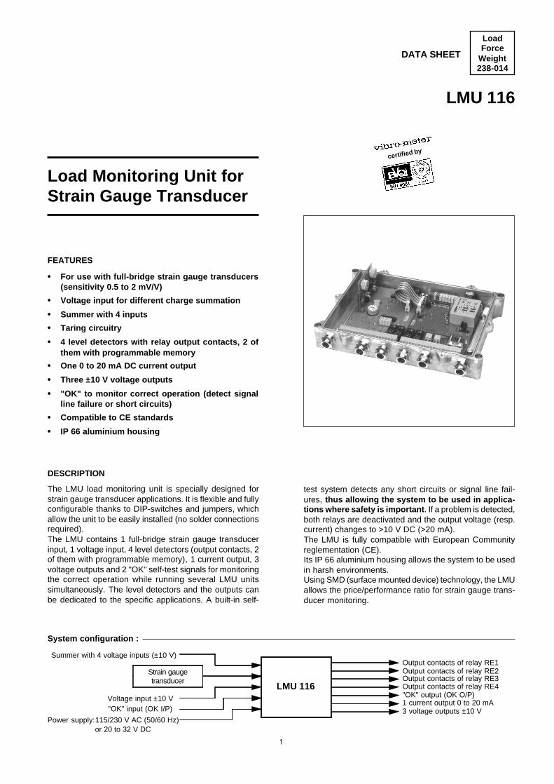
• For use with full-bridge strain gauge transducers(sensitivity 0.5 to 2 mV/V)
• Voltage input for different charge summation
• Summer with 4 inputs
• Taring circuitry
• 4 level detectors with relay output contacts, 2 ofthem with programmable memory
• One 0 to 20 mA DC current output
• Three ±10 V voltage outputs
• "OK" to monitor correct operation (detect signalline failure or short circuits)
• Compatible to CE standards
• IP 66 aluminium housing
LoadForce
Weight238-014
Output contacts of relay RE3Strain gaugetransducer
LMU 116 Output contacts of relay RE4
1 current output 0 to 20 mA3 voltage outputs ±10 V
Power supply:115/230 V AC (50/60 Hz)or 20 to 32 V DC
Voltage input ±10 V
DESCRIPTION
The LMU load monitoring unit is specially designed forstrain gauge transducer applications. It is flexible and fullyconfigurable thanks to DIP-switches and jumpers, whichallow the unit to be easily installed (no solder connectionsrequired).The LMU contains 1 full-bridge strain gauge transducerinput, 1 voltage input, 4 level detectors (output contacts, 2of them with programmable memory), 1 current output, 3voltage outputs and 2 "OK" self-test signals for monitoringthe correct operation while running several LMU unitssimultaneously. The level detectors and the outputs canbe dedicated to the specific applications. A built-in self-
test system detects any short circuits or signal line fail-ures, thus allowing the system to be used in applica-tions where safety is important . If a problem is detected,both relays are deactivated and the output voltage (resp.current) changes to >10 V DC (>20 mA).The LMU is fully compatible with European Communityreglementation (CE).Its IP 66 aluminium housing allows the system to be usedin harsh environments.Using SMD (surface mounted device) technology, the LMUallows the price/performance ratio for strain gauge trans-ducer monitoring.
"OK" input (OK I/P)
"OK" output (OK O/P)
System configuration :
Summer with 4 voltage inputs (±10 V)Output contacts of relay RE1Output contacts of relay RE2
certified by
Load Monitoring Unit forStrain Gauge Transducer
LMU 116
2
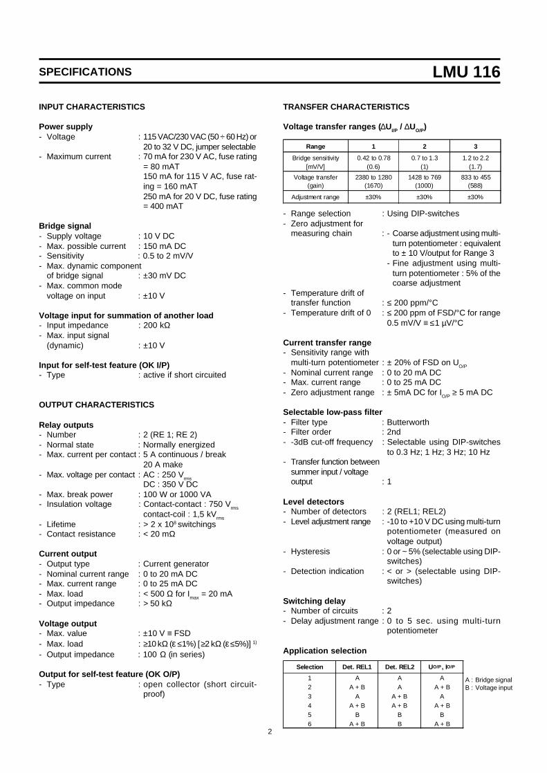
SPECIFICATIONS
INPUT CHARACTERISTICS
Power supply- Voltage : 115 VAC/230 VAC (50 ÷ 60 Hz) or
20 to 32 V DC, jumper selectable- Maximum current : 70 mA for 230 V AC, fuse rating
= 80 mAT150 mA for 115 V AC, fuse rat-ing = 160 mAT250 mA for 20 V DC, fuse rating= 400 mAT
Bridge signal- Supply voltage : 10 V DC- Max. possible current : 150 mA DC- Sensitivity : 0.5 to 2 mV/V- Max. dynamic component
of bridge signal : ±30 mV DC- Max. common mode
voltage on input : ±10 V
Voltage input for summation of another load- Input impedance : 200 kΩ- Max. input signal
(dynamic) : ±10 V
Input for self-test feature (OK I/P)- Type : active if short circuited
OUTPUT CHARACTERISTICS
Relay outputs- Number : 2 (RE 1; RE 2)- Normal state : Normally energized- Max. current per contact : 5 A continuous / break
20 A make- Max. voltage per contact : AC : 250 Vrms
DC : 350 V DC- Max. break power : 100 W or 1000 VA- Insulation voltage : Contact-contact : 750 Vrms
contact-coil : 1,5 kVrms
- Lifetime : > 2 x 10⁸ switchings- Contact resistance : < 20 mΩ
Current output- Output type : Current generator- Nominal current range : 0 to 20 mA DC- Max. current range : 0 to 25 mA DC- Max. load : < 500 Ω for Imax = 20 mA- Output impedance : > 50 kΩ
Voltage output- Max. value : ±10 V ≡ FSD- Max. load : ≥10 kΩ (ε ≤1%) [ ≥2 kΩ (ε ≤5%)] 1)
- Output impedance : 100 Ω (in series)
Output for self-test feature (OK O/P)- Type : open collector (short circuit-
proof)
TRANSFER CHARACTERISTICS
Voltage transfer ranges ( ∆UI/P / ∆UO/P)
Range 1 2 3
Bridge sensitivity[mV/V]
0.42 to 0.78(0.6)
0.7 to 1.3(1)
1.2 to 2.2(1.7)
Voltage transfer(gain)
2380 to 1280(1670)
1428 to 769(1000)
833 to 455(588)
Adjustment range ±30% ±30% ±30%
- Range selection : Using DIP-switches- Zero adjustment for
measuring chain : - Coarse adjustment using multi-turn potentiometer : equivalentto ± 10 V/output for Range 3
- Fine adjustment using multi-turn potentiometer : 5% of thecoarse adjustment
- Temperature drift oftransfer function : ≤ 200 ppm/°C
- Temperature drift of 0 : ≤ 200 ppm of FSD/°C for range0.5 mV/V ≡ ≤1 µV/°C
Current transfer range- Sensitivity range with
multi-turn potentiometer : ± 20% of FSD on UO/P
- Nominal current range : 0 to 20 mA DC- Max. current range : 0 to 25 mA DC- Zero adjustment range : ± 5mA DC for IO/P ≥ 5 mA DC
Selectable low-pass filter- Filter type : Butterworth- Filter order : 2nd- -3dB cut-off frequency : Selectable using DIP-switches
to 0.3 Hz; 1 Hz; 3 Hz; 10 Hz- Transfer function between
summer input / voltageoutput : 1
Level detectors- Number of detectors : 2 (REL1; REL2)- Level adjustment range : -10 to +10 V DC using multi-turn
potentiometer (measured onvoltage output)
- Hysteresis : 0 or ~ 5% (selectable using DIP-switches)
- Detection indication : < or > (selectable using DIP-switches)
Switching delay- Number of circuits : 2- Delay adjustment range : 0 to 5 sec. using multi-turn
potentiometer
Application selection
A : Bridge signalB : Voltage input
Selection Det. REL1 Det. REL2 U O/P, IO/P
1 A A A2 A + B A A + B3 A A + B A4 A + B A + B A + B5 B B B6 A + B B A + B
LMU 116
3
SPECIFICATIONS
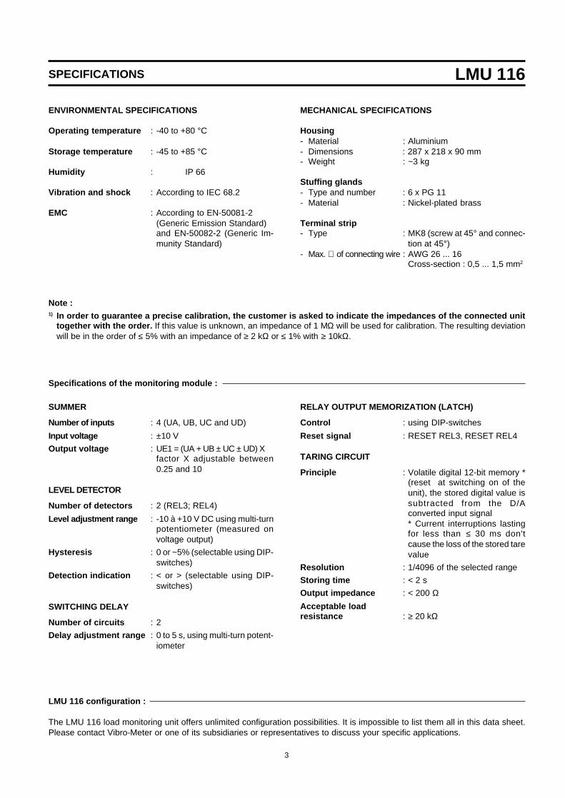
SUMMER
Number of inputs : 4 (UA, UB, UC and UD)
Input voltage : ±10 V
Output voltage : UE1 = (UA + UB ± UC ± UD) Xfactor X adjustable between0.25 and 10
LEVEL DETECTOR
Number of detectors : 2 (REL3; REL4)
Level adjustment range : -10 à +10 V DC using multi-turnpotentiometer (measured onvoltage output)
Hysteresis : 0 or ~5% (selectable using DIP-switches)
Detection indication : < or > (selectable using DIP-switches)
SWITCHING DELAY
Number of circuits : 2
Delay adjustment range : 0 to 5 s, using multi-turn potent-iometer
RELAY OUTPUT MEMORIZATION (LATCH)
Control : using DIP-switches
Reset signal : RESET REL3, RESET REL4
TARING CIRCUIT
Principle : Volatile digital 12-bit memory *(reset at switching on of theunit), the stored digital value issubtracted from the D/Aconverted input signal* Current interruptions lastingfor less than ≤ 30 ms don'tcause the loss of the stored tarevalue
Resolution : 1/4096 of the selected range
Storing time : < 2 s
Output impedance : < 200 ΩAcceptable loadresistance : ≥ 20 kΩ
The LMU 116 load monitoring unit offers unlimited configuration possibilities. It is impossible to list them all in this data sheet.Please contact Vibro-Meter or one of its subsidiaries or representatives to discuss your specific applications.
Specifications of the monitoring module :
LMU 116 configuration :
ENVIRONMENTAL SPECIFICATIONS
Operating temperature : -40 to +80 °C
Storage temperature : -45 to +85 °C
Humidity : IP 66
Vibration and shock : According to IEC 68.2
EMC : According to EN-50081-2(Generic Emission Standard)and EN-50082-2 (Generic Im-munity Standard)
MECHANICAL SPECIFICATIONS
Housing- Material : Aluminium- Dimensions : 287 x 218 x 90 mm- Weight : ~3 kg
Stuffing glands- Type and number : 6 x PG 11- Material : Nickel-plated brass
Terminal strip- Type : MK8 (screw at 45° and connec-
tion at 45°)- Max. ∅ of connecting wire : AWG 26 ... 16
Cross-section : 0,5 ... 1,5 mm2
Note :1) In order to guarantee a precise calibration, the customer is asked to indicate the impedances of the connected unit
together with the order. If this value is unknown, an impedance of 1 MΩ will be used for calibration. The resulting deviationwill be in the order of ≤ 5% with an impedance of ≥ 2 kΩ or ≤ 1% with ≥ 10kΩ.
LMU 116
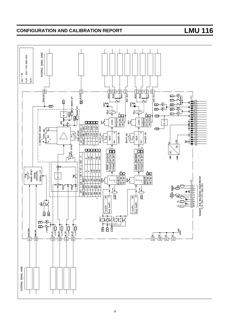
4
CONFIGURATION AND CALIBRATION REPORT
LMU 116
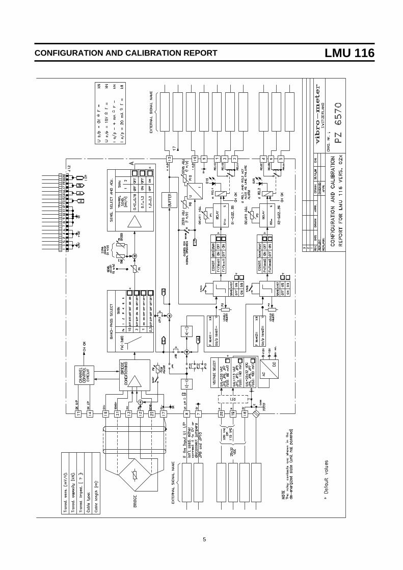
5
CONFIGURATION AND CALIBRATION REPORT

LMU 116
6
DIMENSIONS AND ORDERING INFORMATION
Dimensions :
Ordering information :
- Designation : LMU 116 load monitoring unit
- Ordering number : 224-116-000-021, standard module with no set-up and no calibration.
224-116-000-061, standard module with no set-up and no calibration, including the summerand balancing comparator sub-module.
224-116-000-021C, set-up and calibrated according to the configuration and calibration re-port PY 6494 (to be filled in according to the application).
224-116-000-061C, set-up and calibrated according to the configuration and calibration re-port PY 6494 (to be filled in according to the application), including the summer and balancingcomparator sub-module.
Head Office (Switzerland)Vibro-Meter SA, Rte de Moncor 4,Postfach 1071, CH-1701 FribourgTel. : +41 26-407 11 11Fax Instrumentation : +41 26-407 13 75Fax Industrie & Marine : +41 26-407 13 01Fax Aerospace : +41 26-402 36 62E-mail : [email protected] : www.vibro-meter.com
© VIBRO-METER SA / 238-014 / 10.98 / E
Due to the continual development of our products we reserve the right to modify the specifications without forewarning.
Subsidiaries in :♦ Germany
♦ France
♦ Great Britain
♦ Scandinavia
♦ USA
♦ Canada
♦ Singapore
LOAD MONITORING UNIT CONFIGURATION AND CALIBRATIONLMU 116 VERSIONS 02x AND 02xC
INSTRUCTION MANUAL P/N 633.018 E ISSUE 0 3-1
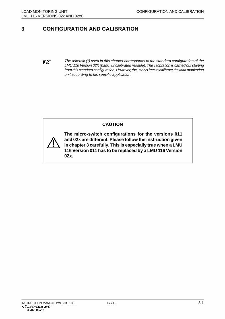
3 CONFIGURATION AND CALIBRATION
The asterisk (*) used in this chapter corresponds to the standard configuration of theLMU 116 Version 02X (basic, uncalibrated module). The calibration is carried out startingfrom this standard configuration. However, the user is free to calibrate the load monitoringunit according to his specific application.
CAUTION
The micro-switch configurations for the versions 011and 02x are different. Please follow the instruction givenin chapter 3 carefully. This is especially true when a LMU116 Version 011 has to be replaced by a LMU 116 Version02x.
CONFIGURATION AND CALIBRATION LOAD MONITORING UNITLMU 116 VERSIONS 02x AND 02xC
3-2 ISSUE 0 INSTRUCTION MANUAL P/N 633.018 E
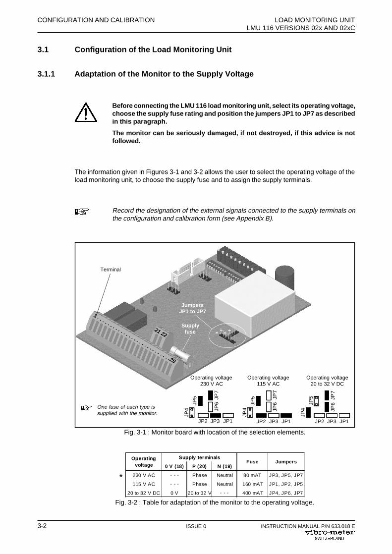
Fig. 3-1 : Monitor board with location of the selection elements.
Supplyfuse
Terminal
One fuse of each type issupplied with the monitor.
JP1JP3JP2
JP7
JP6JP
5
JP4
JP1JP3JP2
JP7
JP6JP
5
JP4
JP1JP3JP2
JP7
JP6JP
5
JP4
Operating voltage230 V AC
Operating voltage115 V AC
Operating voltage20 to 32 V DC
JumpersJP1 to JP7
Supply terminals
0 V (18) P (20) N (19)
230 V AC Phase Neutral 80 mAT JP3, JP5, JP7
115 V AC Phase Neutral 160 mAT JP1, JP2, JP5
20 to 32 V DC 0 V 20 to 32 V 400 mAT JP4, JP6, JP7
Operating voltage
JumpersFuse
- - -
- - -
- - -
Fig. 3-2 : Table for adaptation of the monitor to the operating voltage.
1 . . . . . . . . . . . . . . . . . . . . . . . . . . . .20
21 22
*
3.1 Configuration of the Load Monitoring Unit
3.1.1 Adaptation of the Monitor to the Supply Voltage
Before connecting the LMU 116 load monitoring unit, select its operating voltage,choose the supply fuse rating and position the jumpers JP1 to JP7 as describedin this paragraph.
The monitor can be seriously damaged, if not destroyed, if this advice is notfollowed.
The information given in Figures 3-1 and 3-2 allows the user to select the operating voltage of theload monitoring unit, to choose the supply fuse and to assign the supply terminals.
Record the designation of the external signals connected to the supply terminals onthe configuration and calibration form (see Appendix B).
LOAD MONITORING UNIT CONFIGURATION AND CALIBRATIONLMU 116 VERSIONS 02x AND 02xC
INSTRUCTION MANUAL P/N 633.018 E ISSUE 0 3-3
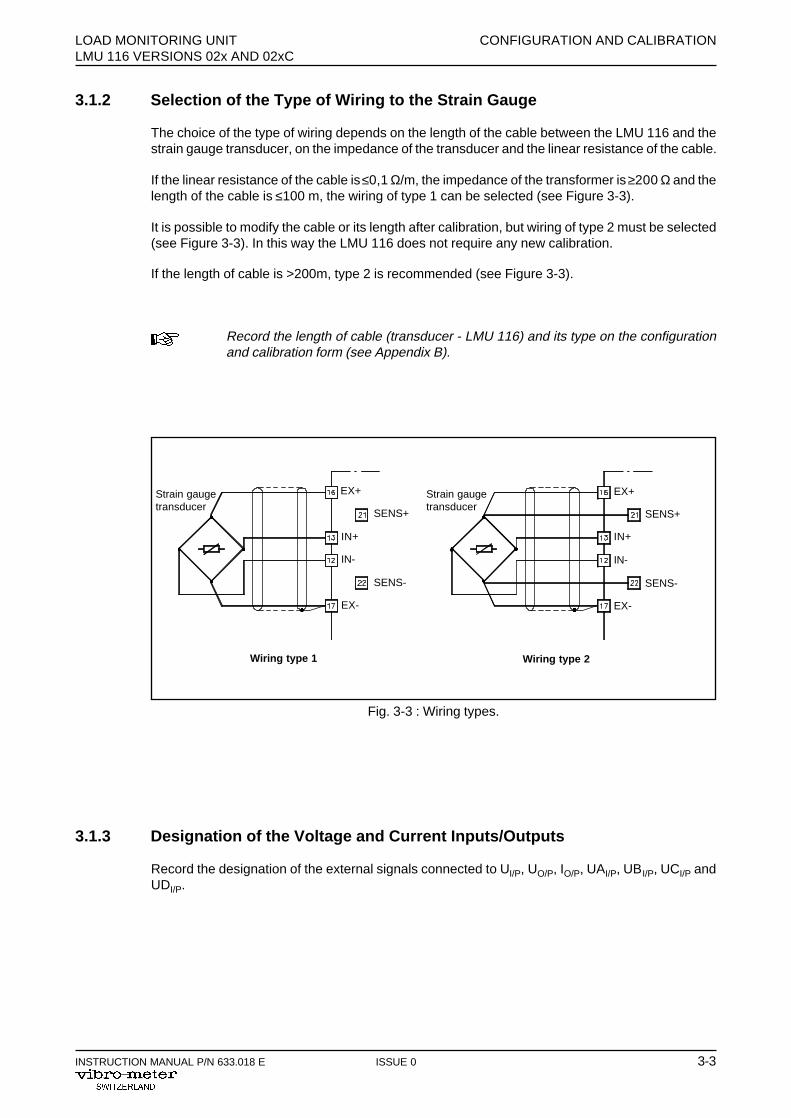
Fig. 3-3 : Wiring types.
Wiring type 1 Wiring type 2
Strain gaugetransducer
EX+
SENS+
IN+
IN-
SENS-
EX-
EX+
SENS+
IN+
IN-
SENS-
EX-
3.1.2 Selection of the Type of Wiring to the Strain Gauge
The choice of the type of wiring depends on the length of the cable between the LMU 116 and thestrain gauge transducer, on the impedance of the transducer and the linear resistance of the cable.
If the linear resistance of the cable is ≤0,1 Ω/m, the impedance of the transformer is ≥200 Ω and thelength of the cable is ≤100 m, the wiring of type 1 can be selected (see Figure 3-3).
It is possible to modify the cable or its length after calibration, but wiring of type 2 must be selected(see Figure 3-3). In this way the LMU 116 does not require any new calibration.
If the length of cable is >200m, type 2 is recommended (see Figure 3-3).
Record the length of cable (transducer - LMU 116) and its type on the configurationand calibration form (see Appendix B).
3.1.3 Designation of the Voltage and Current Inputs/Outputs
Record the designation of the external signals connected to UI/P, UO/P, IO/P, UAI/P, UBI/P, UCI/P andUDI/P.
Strain gaugetransducer
CONFIGURATION AND CALIBRATION LOAD MONITORING UNITLMU 116 VERSIONS 02x AND 02xC
3-4 ISSUE 0 INSTRUCTION MANUAL P/N 633.018 E
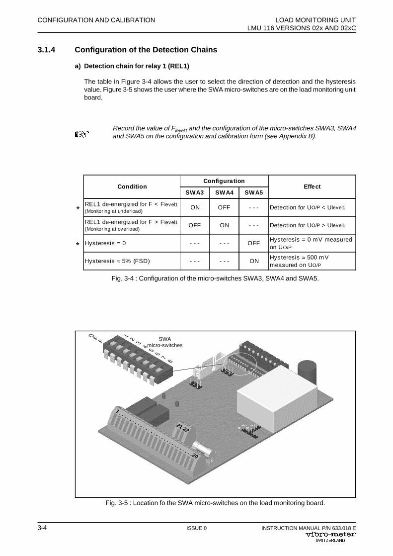
Fig. 3-5 : Location fo the SWA micro-switches on the load monitoring board.
Configuration
SWA3 SWA4 SWA5
REL1 de-energized for F < Flevel1(Monitoring at underload)
ON OFF Detection for UO/P < Ulevel1
REL1 de-energized for F > Flevel1(Monitoring at overload)
OFF ON Detection for UO/P > Ulevel1
Hysteresis = 0 OFFHysteresis = 0 mV measured on UO/P
Hysteresis ≈ 5% (FSD) ONHysteresis ≈ 500 mV measured on UO/P
- - -
- - -
- - -
- - -
- - -
- - -
Condition Effect
Fig. 3-4 : Configuration of the micro-switches SWA3, SWA4 and SWA5.
SWAmicro-switches
12
34
56
78
O F F
*
*
1 . . . . . . . . . . . . . . . . . . . . . . . . . . . .20
21 22
3.1.4 Configuration of the Detection Chains
a) Detection chain for relay 1 (REL1)
The table in Figure 3-4 allows the user to select the direction of detection and the hysteresisvalue. Figure 3-5 shows the user where the SWA micro-switches are on the load monitoring unitboard.
Record the value of Flevel1 and the configuration of the micro-switches SWA3, SWA4and SWA5 on the configuration and calibration form (see Appendix B).
LOAD MONITORING UNIT CONFIGURATION AND CALIBRATIONLMU 116 VERSIONS 02x AND 02xC
INSTRUCTION MANUAL P/N 633.018 E ISSUE 0 3-5
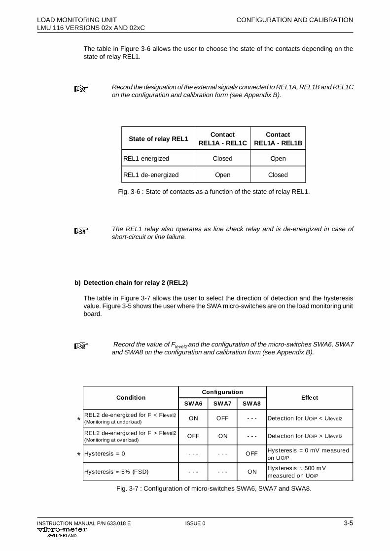
State of relay REL1Contact
REL1A - REL1CContact
REL1A - REL1B
REL1 energized Closed Open
REL1 de-energized Open Closed
Fig. 3-6 : State of contacts as a function of the state of relay REL1.
Configuration
SWA6 SWA7 SWA8
REL2 de-energized for F < Flevel2(Monitoring at underload)
ON OFF Detection for UO/P < Ulevel2
REL2 de-energized for F > Flevel2(Monitoring at overload)
OFF ON Detection for UO/P > Ulevel2
Hysteresis = 0 OFF Hysteresis = 0 mV measured on UO/P
Hysteresis ≈ 5% (FSD) ONHysteresis ≈ 500 mV measured on UO/P
- - -
- - -
- - -
- - -
- - -
- - -
Condition Effect
Fig. 3-7 : Configuration of micro-switches SWA6, SWA7 and SWA8.
*
*
The table in Figure 3-6 allows the user to choose the state of the contacts depending on thestate of relay REL1.
Record the designation of the external signals connected to REL1A, REL1B and REL1Con the configuration and calibration form (see Appendix B).
The REL1 relay also operates as line check relay and is de-energized in case ofshort-circuit or line failure.
b) Detection chain for relay 2 (REL2)
The table in Figure 3-7 allows the user to select the direction of detection and the hysteresisvalue. Figure 3-5 shows the user where the SWA micro-switches are on the load monitoring unitboard.
Record the value of Flevel2 and the configuration of the micro-switches SWA6, SWA7and SWA8 on the configuration and calibration form (see Appendix B).

CONFIGURATION AND CALIBRATION LOAD MONITORING UNITLMU 116 VERSIONS 02x AND 02xC
3-6 ISSUE 0 INSTRUCTION MANUAL P/N 633.018 E
State of relay REL2Contact
REL2A - REL2CContact
REL2A - REL2B
REL2 energized Closed Open
REL2 de-energized Open Closed
Fig. 3-8 : State of contacts as a function of the state of relay REL2.
Configuration
SWC7 SWC8 SWC9 SWC10
REL3 de-energized for F < Flevel3(Monitoring at underload)
OFF ON Detection for UO/P < Ulevel3
REL3 de-energized for F > Flevel3(Monitoring at overload)
ON OFF Detection for UO/P > Ulevel3
Hysteresis = 0 OFFHysteresis = 0 mV measured on UO/P
Hysteresis ≈ 5% (FSD) ONHysteresis ≈ 500 mV measured on UO/P
Unlatched OFFThe relay changes s tate after the alarm has disappeared
Latched (LATCH function) ONRelay stays in the altered state after the alarm has disappeared
- - -
- - -
- - -
- - -
Condition Effect
- - -
- - -
- - -- - -- - -
- - - - - - - - -
- - -
- - -
- - -
- - -
Fig. 3-9 : Configuration of the micro-switches SWC7, SWC8, SWC9 and SWC10.
*
*
*
The table in Figure 3-8 allows the user to select the state of the contacts depending on the stateof relay REL2.
Record the designation of the external signals connected to REL2A, REL2B and REL2Con the configuration and calibration form (see Appendix B).
The REL2 relay also operates as line check relay and is de-energized in case ofshort-circuit of line failure.
c) Detection chain for relay 3 (REL3)
The table in Figure 3-9 allows the user to select the direction of the detection as well as thehysteresis value and whether latching is used. Figure 3-10 informs the user of the positions ofthe SWC micro-switches on the load monitoring unit circuit board.
Record the value of Flevel3 and the configuration of the micro-switches SWC7, SWC8,SWC9 and SWC10 (see Appendix B).

LOAD MONITORING UNIT CONFIGURATION AND CALIBRATIONLMU 116 VERSIONS 02x AND 02xC
INSTRUCTION MANUAL P/N 633.018 E ISSUE 0 3-7
Fig. 3-10 : Location of the SWC micro-switches on the load monitoring board.
SWCmicro-switches
31 . . . . . . . . . . . . . . . . . . . . . . . . . . .50
State of relay REL3Contact
REL3A - REL3CContact
REL3A - REL3B
REL3 energized Closed Open
REL3 de-energized Open Closed
Fig. 3-11 : State of contacts as a function of the state of relay REL3.
Option : Comparator
The table in Figure 3-11 allows the user to choose the state of the contacts depending on thestate of relay REL3.
Record the designation of the external signals connected to REL3A, REL3B and REL3Con the configuration and calibration form (see Appendix B).
1 2 3 4 5 6 7 8 910
O F F
CONFIGURATION AND CALIBRATION LOAD MONITORING UNITLMU 116 VERSIONS 02x AND 02xC
3-8 ISSUE 0 INSTRUCTION MANUAL P/N 633.018 E
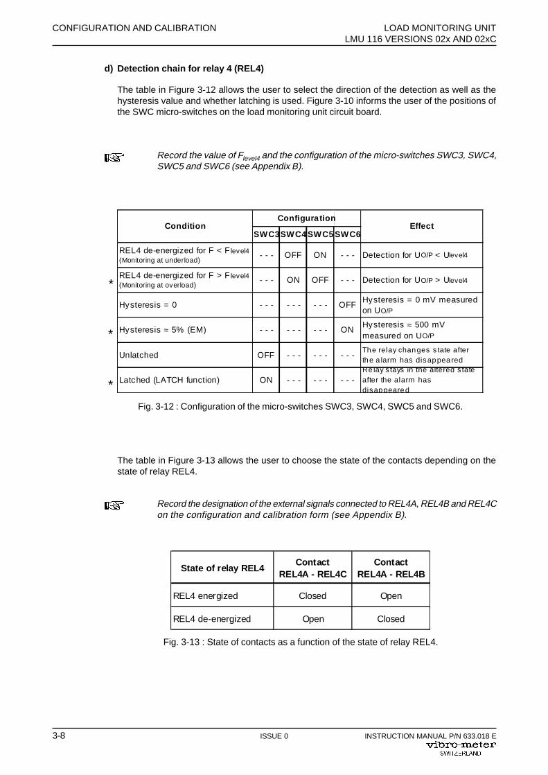
Configuration
SWC3SWC4 SWC5 SWC6
REL4 de-energized for F < F level4(Monitoring at underload)
OFF ON Detection for UO/P < Ulevel4
REL4 de-energized for F > F level4(Monitoring at overload)
ON OFF Detection for UO/P > Ulevel4
Hysteresis = 0 OFFHysteresis = 0 mV measured on UO/P
Hysteresis ≈ 5% (EM) ONHysteresis ≈ 500 mV measured on UO/P
Unlatched OFFThe relay changes s tate after the a larm has disappeared
Latched (LATCH function) ONRe lay s tays in the altered s tate after the alarm has disappeared
- - -
- - -
- - -
- - -
Condition Effect
- - -
- - -
- - -- - -- - -
- - - - - - - - -
- - -
- - -
- - -
- - -
Fig. 3-12 : Configuration of the micro-switches SWC3, SWC4, SWC5 and SWC6.
*
*
*
State of relay REL4Contact
REL4A - REL4CContact
REL4A - REL4B
REL4 energized Closed Open
REL4 de-energized Open Closed
Fig. 3-13 : State of contacts as a function of the state of relay REL4.
d) Detection chain for relay 4 (REL4)
The table in Figure 3-12 allows the user to select the direction of the detection as well as thehysteresis value and whether latching is used. Figure 3-10 informs the user of the positions ofthe SWC micro-switches on the load monitoring unit circuit board.
Record the value of Flevel4 and the configuration of the micro-switches SWC3, SWC4,SWC5 and SWC6 (see Appendix B).
The table in Figure 3-13 allows the user to choose the state of the contacts depending on thestate of relay REL4.
Record the designation of the external signals connected to REL4A, REL4B and REL4Con the configuration and calibration form (see Appendix B).

LOAD MONITORING UNIT CONFIGURATION AND CALIBRATIONLMU 116 VERSION 02x AND 02xC
INSTRUCTION MANUAL P/N 633.018 E ISSUE 0 3-9
UO/P
UO/P
F > Flevel1(2,3,4)
F < Flevel1(2,3,4)
Ulevel1(2,3,4)
Ulevel1(2,3,4)
t
t
REL1(2,3,4) energized REL1(2,3,4)energized
REL1(2,3,4)de-energized
REL1(2,3,4) energized REL1(2,3,4)energized
REL1(2,3,4)de-energized
ED DD ED DD
ED DD EDDD
Switching delayD
Switching delayD
E ≡ Tripping of the switching delay
D ≡ Release of the switching delay
Fig. 3-14 : Examples of switching delays for the load monitoring unit.
e) Adjusting the switching delay
The switching delay corresponds to the time passing between the moment when the detectionlevel is reached at the voltage output of the LMU (UO/P) and the moment when the relay is de-energized (see Figure 3-14). On the other hand, the switching delay on tripping of the relay inrelation to the voltage output of the LMU (UO/P) is instantaneous.
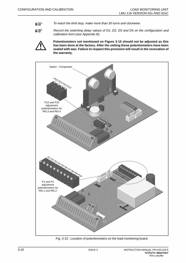
To set the switching delay to be applied to the REL1 relay, adjust potentiometer P1. To set theswitching delay to be applied to relay REL2, REL3 and REL4, adjust potentiometer P2, P13 andP15. Figure 3-15 shows the user where the potentiometers are located on the load monitoringunit board.
The method of adjustment is as follows :
D1 = Switching delay on REL1
To determine the switching delay value, calculate the number of turns to be applied to thepotentiometers :
ND
11 0 02
0164= − .
.with N1 = number of turns to be applied to potentiometer P1
D1 = switching delay required for relay REL1 in secondsD1min = 0.02 sec.D1max = 5 sec.
Apply the calculated number of turns (N) by counting them starting at 0 (the potentiometer at itslimit stop in the anti-clockwise sense) and by turning the potentiometer clockwise.
CONFIGURATION AND CALIBRATION LOAD MONITORING UNITLMU 116 VERSION 02x AND 02xC
3-10 ISSUE 0 INSTRUCTION MANUAL P/N 633.018 E
31 . . . . . . . . . . . . . . . . . . . . . . . . . . .50
Fig. 3-15 : Location of potentiometers on the load monitoring board.
P1 and P2adjustment
potentiometers forREL1 and REL2
P1 P2 P3 P4 P5 P6 P7 P8 P9 P10
P13 and P15adjustment
potentiometers forREL3 and REL4
P15 P14 P13 P12
1 . . . . . . . . . . . . . . . . . . . . . . . . . . . .20
21 22
Option : Comparator
To reach the limit stop, make more than 30 turns anti-clockwise.
Record the switching delay values of D1, D2, D3 and D4 on the configuration andcalibration form (see Appendix B).
Potentiometers not mentioned on Figure 3-15 should not be adjusted as thishas been done at the factory. After the setting these potentiometers have beensealed with wax. Failure to respect this provision will result in the revocation ofthe warranty.
LOAD MONITORING UNIT CONFIGURATION AND CALIBRATIONLMU 116 VERSION 02x AND 02xC
INSTRUCTION MANUAL P/N 633.018 E ISSUE 0 3-11
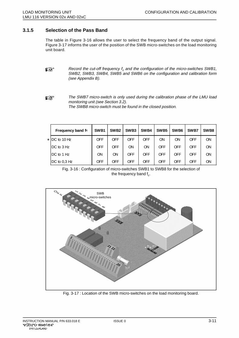
Fig. 3-17 : Location of the SWB micro-switches on the load monitoring board.
SWBmicro-switches
12
34
56
78
O F F
Frequency band f c SWB1 SWB2 SWB3 SWB4 SWB5 SWB6 SWB7 SWB8
DC to 10 Hz OFF OFF OFF OFF ON ON OFF ON
DC to 3 Hz OFF OFF ON ON OFF OFF OFF ON
DC to 1 Hz ON ON OFF OFF OFF OFF OFF ON
DC to 0,3 Hz OFF OFF OFF OFF OFF OFF OFF ON
Fig. 3-16 : Configuration of micro-switches SWB1 to SWB8 for the selection ofthe frequency band fc.
*
3.1.5 Selection of the Pass Band
The table in Figure 3-16 allows the user to select the frequency band of the output signal.Figure 3-17 informs the user of the position of the SWB micro-switches on the load monitoringunit board.
Record the cut-off frequency fc and the configuration of the micro-switches SWB1,SWB2, SWB3, SWB4, SWB5 and SWB6 on the configuration and calibration form(see Appendix B).
The SWB7 micro-switch is only used during the calibration phase of the LMU loadmonitoring unit (see Section 3.2).The SWB8 micro-switch must be found in the closed position.
1 . . . . . . . . . . . . . . . . . . . . . . . . . . . .20
21 22
CONFIGURATION AND CALIBRATION LOAD MONITORING UNITLMU 116 VERSION 02x AND 02xC
3-12 ISSUE 0 INSTRUCTION MANUAL P/N 633.018 E
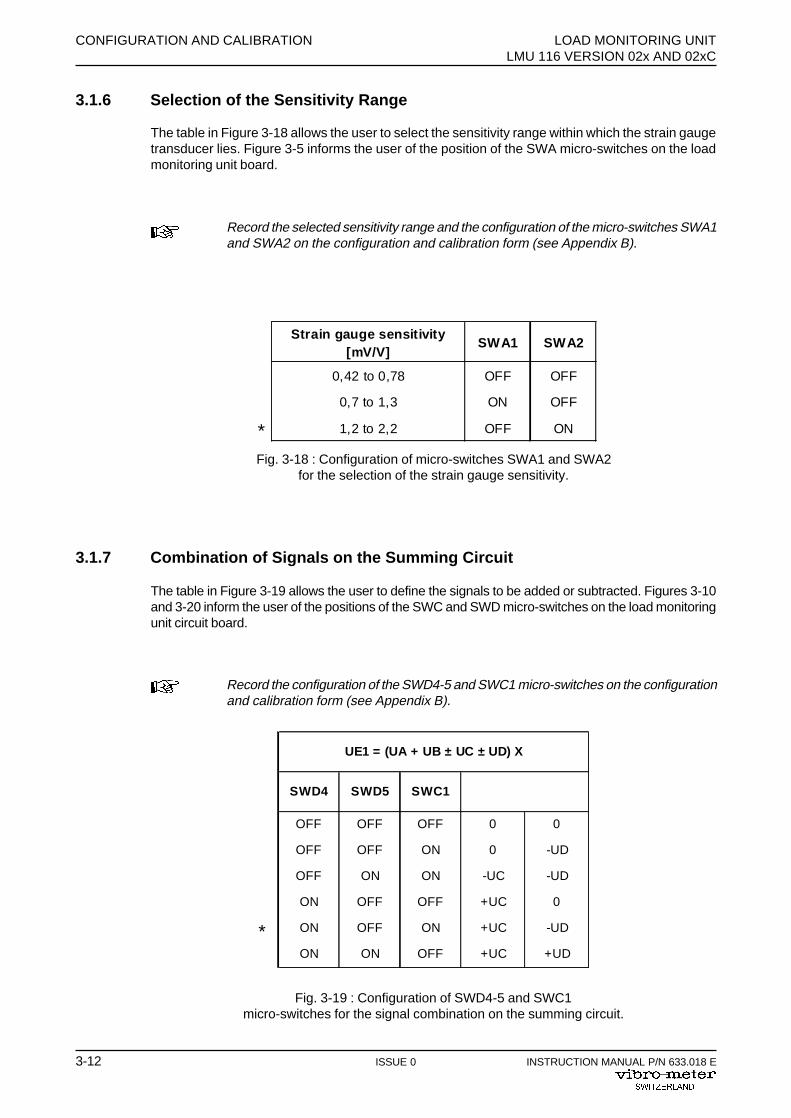
Strain gauge sensitivity[mV/V]
SWA1 SWA2
0,42 to 0,78 OFF OFF
0,7 to 1,3 ON OFF
1,2 to 2,2 OFF ON
Fig. 3-18 : Configuration of micro-switches SWA1 and SWA2for the selection of the strain gauge sensitivity.
*
Fig. 3-19 : Configuration of SWD4-5 and SWC1micro-switches for the signal combination on the summing circuit.
3.1.6 Selection of the Sensitivity Range
The table in Figure 3-18 allows the user to select the sensitivity range within which the strain gaugetransducer lies. Figure 3-5 informs the user of the position of the SWA micro-switches on the loadmonitoring unit board.
Record the selected sensitivity range and the configuration of the micro-switches SWA1and SWA2 on the configuration and calibration form (see Appendix B).
3.1.7 Combination of Signals on the Summing Circuit
The table in Figure 3-19 allows the user to define the signals to be added or subtracted. Figures 3-10and 3-20 inform the user of the positions of the SWC and SWD micro-switches on the load monitoringunit circuit board.
Record the configuration of the SWD4-5 and SWC1 micro-switches on the configurationand calibration form (see Appendix B).
UE1 = (UA + UB ± UC ± UD) X
SWD4 SWD5 SWC1
OFF OFF OFF 0 0
OFF OFF ON 0 -UD
OFF ON ON -UC -UD
ON OFF OFF +UC 0
ON OFF ON +UC -UD
ON ON OFF +UC +UD
*
LOAD MONITORING UNIT CONFIGURATION AND CALIBRATIONLMU 116 VERSION 02x AND 02xC
INSTRUCTION MANUAL P/N 633.018 E ISSUE 0 3-13
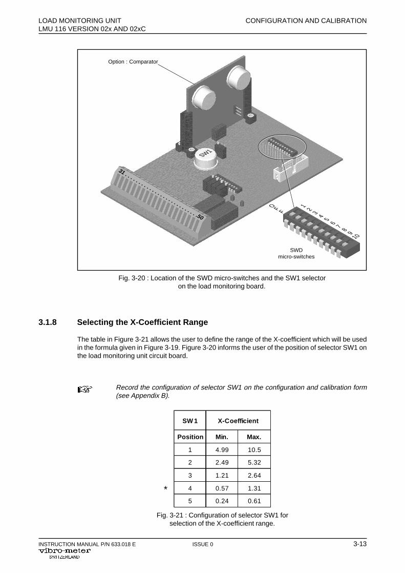
Fig. 3-20 : Location of the SWD micro-switches and the SW1 selectoron the load monitoring board.
31 . . . . . . . . . . . . . . . . . . . . . . . . . . .50
SWDmicro-switches
1 2 3 4 5 6 7 8 910
O F F
SW1
SW 1 X-Coefficient
Position Min. Max.
1 4.99 10.5
2 2.49 5.32
3 1.21 2.64
4 0.57 1.31
5 0.24 0.61
Fig. 3-21 : Configuration of selector SW1 forselection of the X-coefficient range.
Option : Comparator
3.1.8 Selecting the X-Coefficient Range
The table in Figure 3-21 allows the user to define the range of the X-coefficient which will be usedin the formula given in Figure 3-19. Figure 3-20 informs the user of the position of selector SW1 onthe load monitoring unit circuit board.
Record the configuration of selector SW1 on the configuration and calibration form(see Appendix B).
*
CONFIGURATION AND CALIBRATION LOAD MONITORING UNITLMU 116 VERSION 02x AND 02xC
3-14 ISSUE 0 INSTRUCTION MANUAL P/N 633.018 E
3.2 Calibration of the Load Monitoring Unit
3.2.1 Zero Adjustment on the Voltage Output
The following conditions are required to adjust the zero on the voltage output :
- the load applied to the strain gauge transducer F = 0,- the micro-switch SWB7 = OFF.
Connect a numerical millivoltmeter between terminals 15 (UO/P) and 9 (0 V) of the load monitoringunit.
Adjust P6 then P7 (see Figure 3-15 for their location, circuit of the lower part) to 0 V ±10 mV on themillivoltmeter.
3.2.2 Zero Adjustment on the Current Output
The following conditions are required to adjust the zero on the current output :
- the load applied to the strain gauge transducer F = 0,- The micro-switch SWB7 = OFF.
Connect a numerical milliammeter between terminals 10 (IO/P) and 9 (0 V) of the load monitoringunit.
Adjust P8 (see Figure 3-15 for the location, circuit of the lower part) to the initial value ±50 µA (e.g.4 mA ±50 µA) on the milliammeter.
3.2.3 Sensitivity Adjustment on the Voltage Output
To adjust the sensitivity on the voltage output (UO/P), carry out the following operations :
Apply a known load (Fknown > 0,5FN) to the strain gauge transducer.
With : FN ≡ nominal strain gauge transducer load
FN ≡ UO/P nominal = 10 V DC
UO/P known ≡ Fknown
To determine the rating of the voltage output, carry out the following calculation :
U10V F
FO/P knownknown
N= ⋅
Connect a digital millivoltmeter between terminals 15 (UO/P) and 9 (0 V) of the load monitoring unit.
Adjust P4 (see Figure 3-15 for the location, circuit of the lower part) to UO/P known with an accuracyof ±10 mV.

LOAD MONITORING UNIT CONFIGURATION AND CALIBRATIONLMU 116 VERSION 02x AND 02xC
INSTRUCTION MANUAL P/N 633.018 E ISSUE 0 3-15
3.2.4 Sensitivity Adjustment on the Current Output
To adjust the sensitivity on the current output (IO/P) , the load applied to the strain gauge transducerFknown must be maintained and the sensitivity on the voltage output (UO/P) must be adjusted first.
To determine the rating of the current output make the following calculation :
I16mA F
Finitial value (e.g. 4 mA)O/P known
known
N= ⋅ +
Connect a milliammeter between the terminals 10 (IO/P) and 9 (0 V) of the load monitoring unit.
Adjust P10 (see Figure 3-10 for the location, circuit of the lower part) to IO/P known with an accuracyof ±50 µA.
3.2.5 Adjustment of the U level1 and U level2 Detection Thresholds
The following conditions are required to adjust the detection thresholds :
- the load applied to the strain gauge transducer F = 0,- the micro-switch SWB7 = ON (injected test signal),- UO/P must be connected to UO/Plevel2 by connecting the JP8 jumper.
Calculate the threshold voltages in relation to the voltage output UO/P :
U10V F
FO/P level1level1
N= ⋅
U10V F
FO/P level2level2
N= ⋅
• Adjustment of detection threshold U level1
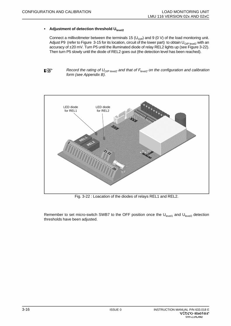
Connect a millivoltmeter between the terminals 15 (UO/P) and 9 (0 V) of the load monitoringunit. Adjust P9 (refer to Figure 3-15 for its location, circuit of the lower part) to obtain UO/P level1with an accuracy of ±20 mV. Turn P3 until the illuminated diode of relay REL1 lights up (seeFigure 3-22). Then turn P3 slowly until the diode of REL1 goes out (the detection level hasbeen reached).
Record the rating of UO/P level1 and that of Flevel1 on the configuration and calibrationform (see Appendix B).
CONFIGURATION AND CALIBRATION LOAD MONITORING UNITLMU 116 VERSION 02x AND 02xC
3-16 ISSUE 0 INSTRUCTION MANUAL P/N 633.018 E
Fig. 3-22 : Loacation of the diodes of relays REL1 and REL2.
LED diodefor REL1
LED diodefor REL2
REL1
REL21 . . . . . . . . . . . . . . . . . . . . . . . . . . . .20
21 22
• Adjustment of detection threshold U level2
Connect a millivoltmeter between the terminals 15 (UO/P) and 9 (0 V) of the load monitoring unit.Adjust P9 (refer to Figure 3-15 for its location, circuit of the lower part) to obtain UO/P level2 with anaccuracy of ±20 mV. Turn P5 until the illuminated diode of relay REL2 lights up (see Figure 3-22).Then turn P5 slowly until the diode of REL2 goes out (the detection level has been reached).
Record the rating of UO/P level2 and that of Flevel2 on the configuration and calibrationform (see Appendix B).
Remember to set micro-switch SWB7 to the OFF position once the Ulevel1 and Ulevel2 detectionthresholds have been adjusted.

LOAD MONITORING UNIT CONFIGURATION AND CALIBRATIONLMU 116 VERSION 02x AND 02xC
INSTRUCTION MANUAL P/N 633.018 E ISSUE 0 3-17
3.2.6 Adjustment of the U level3 and U level4 Detection Thresholds
The following conditions are required to adjust the detection thresholds :
- the load applied to the strain gauge transducer F = 0,- the micro-switch SWB7 = ON (injected test signal),- UO/P must be connected to UO/Plevel3 and UO/Plevel4 by checking the signal passes through C1
and by connecting the JP37 and JP38 jumpers (see wiring diagram on Figure 4-2).
Calculate the threshold voltages in relation to the voltage output UO/P :
U10V F
FO /P level3
leve l3
N
=⋅
U10V F
FO /P level4
level4
N
=⋅
• Adjustment of detection threshold U level3
Connect a millivoltmeter between the terminals 15 (UO/P) and 9 (0 V) of the load monitoringunit. Adjust P9 (refer to Figure 3-15 for its location, circuit of the lower part) to obtain UO/P level3with an accuracy of ±20 mV. Turn P12 until the illuminated diode of relay REL3 lights up (seeFigure 3-23). Then turn P12 slowly until the diode of REL3 goes out (the detection level hasbeen reached).
Record the rating of UO/P level3 and that of Flevel3 on the configuration and calibrationform (see Appendix B).
• Adjustment of detection threshold U level4
Connect a millivoltmeter between the terminals 15 (UO/P) and 9 (0 V) of the load monitoring unit.Adjust P9 (refer to Figure 3-15 for its location, circuit of the lower part) to obtain UO/P level4 withan accuracy of ±20 mV. Turn P14 until the illuminated diode of relay REL4 lights up (see Figure3-23). Then turn P14 slowly until the diode of REL4 goes out (the detection level has beenreached).
Record the rating of UO/P level4 and that of Flevel4 on the configuration and calibrationform (see Appendix B).
Remember to set micro-switch SWB7 to the OFF position once the Ulevel3 and Ulevel4 detectionthresholds have been adjusted.
CONFIGURATION AND CALIBRATION LOAD MONITORING UNITLMU 116 VERSION 02x AND 02xC
3-18 ISSUE 0 INSTRUCTION MANUAL P/N 633.018 E
31 . . . . . . . . . . . . . . . . . . . . . . . . . . .50
P15 P14 P13 P12
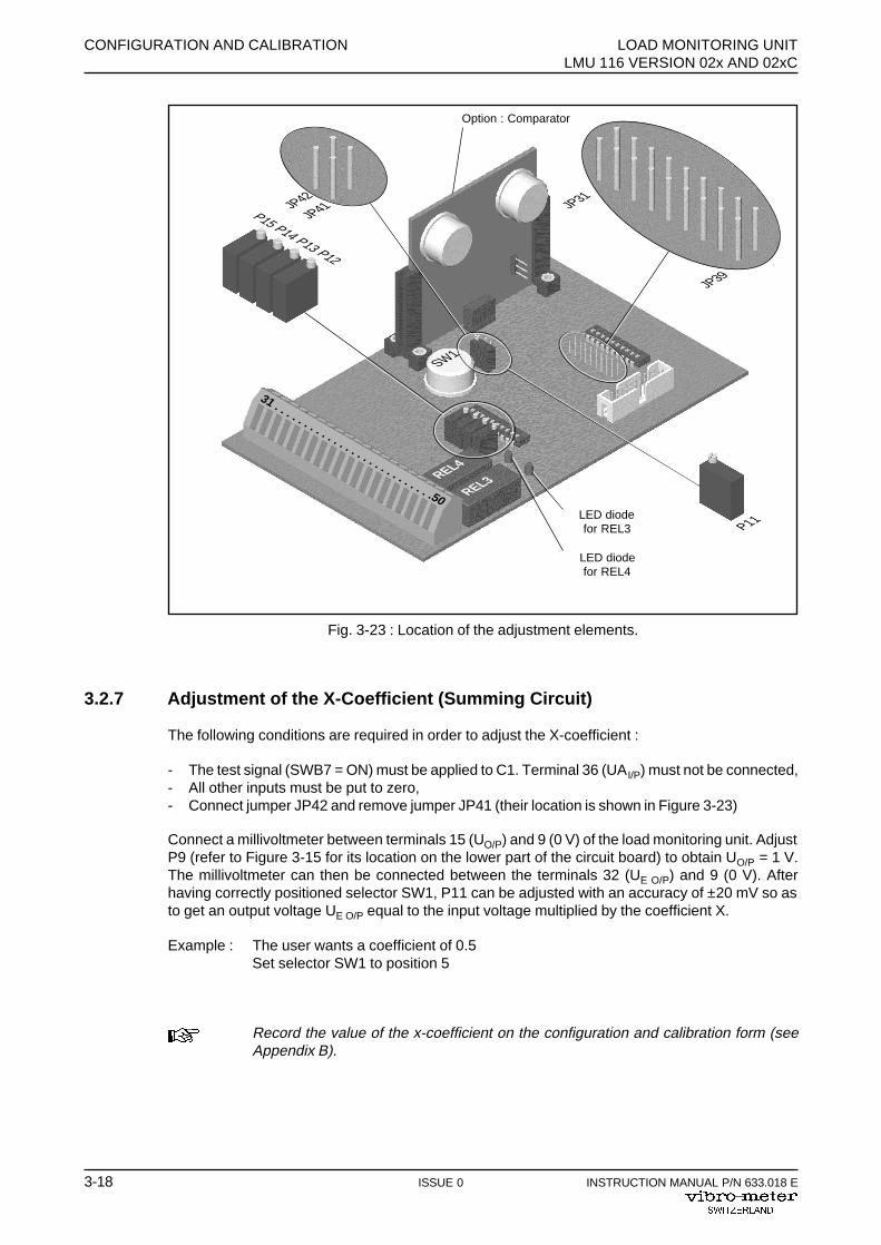
Fig. 3-23 : Location of the adjustment elements.
LED diodefor REL3
LED diodefor REL4
REL4
REL3
3.2.7 Adjustment of the X-Coefficient (Summing Circuit)
The following conditions are required in order to adjust the X-coefficient :
- The test signal (SWB7 = ON) must be applied to C1. Terminal 36 (UAI/P) must not be connected,- All other inputs must be put to zero,- Connect jumper JP42 and remove jumper JP41 (their location is shown in Figure 3-23)
Connect a millivoltmeter between terminals 15 (UO/P) and 9 (0 V) of the load monitoring unit. AdjustP9 (refer to Figure 3-15 for its location on the lower part of the circuit board) to obtain UO/P = 1 V.The millivoltmeter can then be connected between the terminals 32 (UE O/P) and 9 (0 V). Afterhaving correctly positioned selector SW1, P11 can be adjusted with an accuracy of ±20 mV so asto get an output voltage UE O/P equal to the input voltage multiplied by the coefficient X.
Example : The user wants a coefficient of 0.5Set selector SW1 to position 5
Record the value of the x-coefficient on the configuration and calibration form (seeAppendix B).
P11
JP31
JP39
JP42
JP41
SW1
Option : Comparator

LOAD MONITORING UNIT CONFIGURATION AND CALIBRATIONLMU 116 VERSION 02x AND 02xC
INSTRUCTION MANUAL P/N 633.018 E ISSUE 0 3-19
3.3 Configuration of the taring circuitry
The LMU 116 is fitted with a taring circuitry. This circuitry allows one to force a measured signal tozero by means of external instructions (AUTO-ZERO terminal 42 and COM-TAR terminal 40). Thisnew value, called NET is available on the output TARING O/P (terminal 38).
The output TARING O/P follows the rule NET = GROSS - TARE.
3.3.1 AUTO-TARE
To add a tare to a measured signal : connect input COM-TAR (terminal 40) to 0 V (terminal 41) fora minimum time of 1 second.
3.3.2 RESET-TARE
To remove the tare of the measured signal : connect AUTO-ZERO (terminal 42) to 0 V (terminal 41)for a minimum time of 1 second.
3.3.3 Selection of the TARE signal
The micro-switches SWD 6 and 7 (see fig. 3-20 indicating their location on the printed circuit board),as well as the jumper JP41 (see fig. 3-23 indicating its location on the printed circuit board) allowsone to select the taring circuitry input value. This value corresponds to the TARE signal, which willbe subtracted to obtain the NET signal NET (TARING O/P, terminal 38).
Fig. 3-24 : Taring circuitry
Taring circuitry input signal (gross w eight) SWD 6 SWD 7JP41
(see appe ndix B)
Amplified transducer (C1) s ignal ON OFF - - -
Output signal of the summer (E2) OFF ON ON
Optional submodule output signal (SUMMER O/P P/N 224-107-400-02x)
OFF ON OFF
Taring system out of order OFF OFF - - -
CONFIGURATION AND CALIBRATION LOAD MONITORING UNITLMU 116 VERSION 02x AND 02xC
3-20 ISSUE 0 INSTRUCTION MANUAL P/N 633.018 E
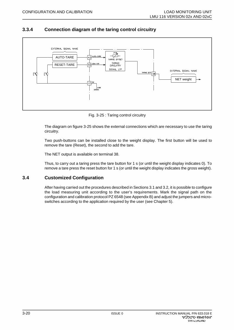
3.3.4 Connection diagram of the taring control circuitry
The diagram on figure 3-25 shows the external connections which are necessary to use the taringcircuitry.
Two push-buttons can be installed close to the weight display. The first button will be used toremove the tare (Reset), the second to add the tare.
The NET output is available on terminal 38.
Thus, to carry out a taring press the tare button for 1 s (or until the weight display indicates 0). Toremove a tare press the reset button for 1 s (or until the weight display indicates the gross weight).
3.4 Customized Configuration
After having carried out the procedures described in Sections 3.1 and 3.2, it is possible to configurethe load measuring unit according to the user’s requirements. Mark the signal path on theconfiguration and calibration protocol PZ 6548 (see Appendix B) and adjust the jumpers and micro-switches according to the application required by the user (see Chapter 5).
Fig. 3-25 : Taring control circuitry
AUTO-TARE
RESET-TARE
NET weight
LOAD MONITORING UNIT ASSEMBLY AND CONNECTIONLMU 116 VERSION 02x AND 02xC
INSTRUCTION MANUAL P/N 633.018 E ISSUE 0 4-1
4 ASSEMBLY AND CONNECTION
4.1 General
So that the means used to carry out the assembly and connection of the load monitoring unitLMU 116 are suitable and so that the signals recorded do not suffer any disruption caused byincorrect procedures, follow and apply the procedures indicated in this chapter.
The procedures contained in this chapter do not cover every assembly and connectionoption. However, they allow the user to gain inspiration from specific applications. If indoubt, the user should contact Vibro-Meter so that a solution which does not disruptthe measurements can be found.Also the user should respect the general instructions of the machine manufacturersand the standards and specifications on the subject of safety and special construction.
ASSEMBLY AND CONNECTION LOAD MONITORING UNITLMU 116 VERSION 02x AND 02xC
4-2 ISSUE 0 INSTRUCTION MANUAL P/N 633.018 E
4.2 Assembly of the Load Monitoring Unit
Make sure that the temperature in the area where the load monitoring unit is to belocated is between -40°C and +80°C.
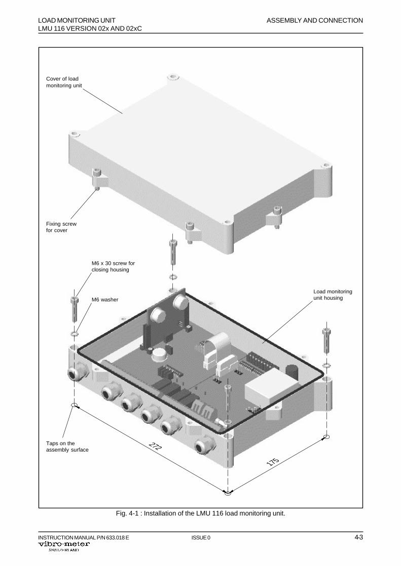
- Choose an assembly location free of vibrations (e.g. instrument support base)
- Mark the position of 4 tapping points on the assembly surface (see Figure 4-1).
- Drill and tap the four M6 holes. The taps should be ~15 mm.
- Remove the cover of the load monitoring unit housing by unscrewing its six screws (seeFigure 4-1).
- Position the housing on the assembly surface and tighten up the four M6 x 30 fixing screws.Adopt a torque suitable for the type of screw used.
- If the configuration and calibration of the monitor have not been done, do them using theprocedures described in Chapter 3.
- Make the electrical connections in accordance with the specifications given in Section 4.3.
- Put the cover back on the load monitoring unit housing and tighten up its six screws.
LOAD MONITORING UNIT ASSEMBLY AND CONNECTIONLMU 116 VERSION 02x AND 02xC
INSTRUCTION MANUAL P/N 633.018 E ISSUE 0 4-3
Fig. 4-1 : Installation of the LMU 116 load monitoring unit.
175
272
Cover of loadmonitoring unit
Fixing screwfor cover
M6 x 30 screw forclosing housing
Load monitoringunit housing
Taps on theassembly surface
M6 washer
ASSEMBLY AND CONNECTION LOAD MONITORING UNITLMU 116 VERSION 02x AND 02xC
4-4 ISSUE 0 INSTRUCTION MANUAL P/N 633.018 E
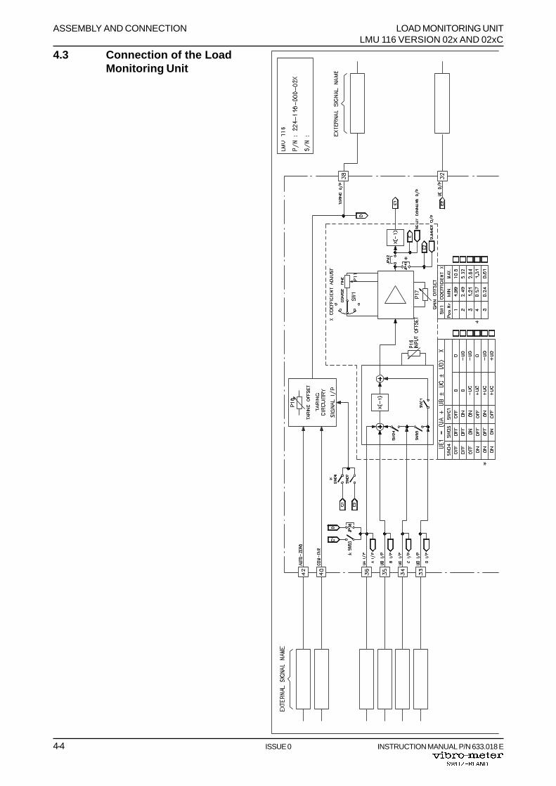
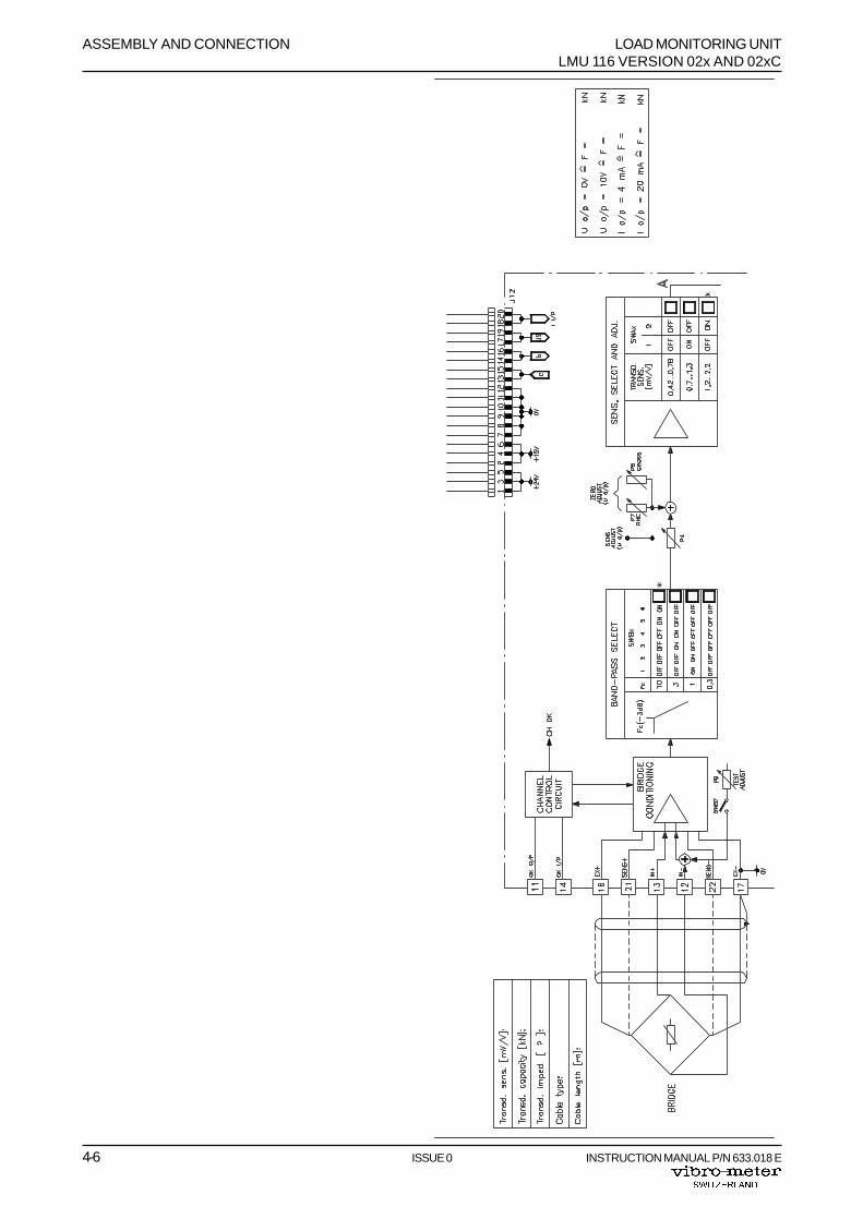
4.3 Connection of the LoadMonitoring Unit

LOAD MONITORING UNIT ASSEMBLY AND CONNECTIONLMU 116 VERSION 02x AND 02xC
INSTRUCTION MANUAL P/N 633.018 E ISSUE 0 4-5
Fig. 4-2 : General wiring diagram(part 1of 2).
ASSEMBLY AND CONNECTION LOAD MONITORING UNITLMU 116 VERSION 02x AND 02xC
4-6 ISSUE 0 INSTRUCTION MANUAL P/N 633.018 E
LOAD MONITORING UNIT ASSEMBLY AND CONNECTIONLMU 116 VERSION 02x AND 02xC
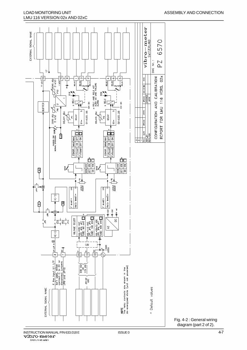
INSTRUCTION MANUAL P/N 633.018 E ISSUE 0 4-7
Fig. 4-2 : General wiringdiagram (part 2 of 2).
ASSEMBLY AND CONNECTION LOAD MONITORING UNITLMU 116 VERSION 02x AND 02xC
4-8 ISSUE 0 INSTRUCTION MANUAL P/N 633.018 E
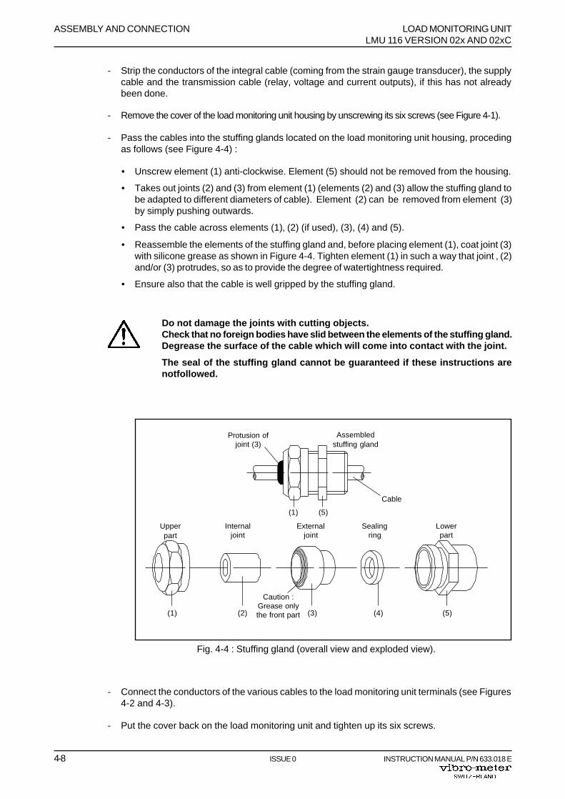
Fig. 4-4 : Stuffing gland (overall view and exploded view).
(3)(2) (4) (5)(1)
Assembledstuffing gland
(1) (5)
Sealingring
Lowerpart
Internaljoint
Externaljoint
Upperpart
Cable
Protusion ofjoint (3)
Caution :Grease onlythe front part
- Strip the conductors of the integral cable (coming from the strain gauge transducer), the supplycable and the transmission cable (relay, voltage and current outputs), if this has not alreadybeen done.
- Remove the cover of the load monitoring unit housing by unscrewing its six screws (see Figure 4-1).
- Pass the cables into the stuffing glands located on the load monitoring unit housing, procedingas follows (see Figure 4-4) :
• Unscrew element (1) anti-clockwise. Element (5) should not be removed from the housing.
• Takes out joints (2) and (3) from element (1) (elements (2) and (3) allow the stuffing gland tobe adapted to different diameters of cable). Element (2) can be removed from element (3)by simply pushing outwards.
• Pass the cable across elements (1)‚ (2) (if used), (3), (4) and (5).
• Reassemble the elements of the stuffing gland and, before placing element (1), coat joint (3)with silicone grease as shown in Figure 4-4. Tighten element (1) in such a way that joint ‚ (2)and/or (3) protrudes, so as to provide the degree of watertightness required.
• Ensure also that the cable is well gripped by the stuffing gland.
Do not damage the joints with cutting objects.Check that no foreign bodies have slid between the elements of the stuffing gland.Degrease the surface of the cable which will come into contact with the joint.
The seal of the stuffing gland cannot be guaranteed if these instructions arenotfollowed.
- Connect the conductors of the various cables to the load monitoring unit terminals (see Figures4-2 and 4-3).
- Put the cover back on the load monitoring unit and tighten up its six screws.
LOAD MONITORING UNIT APPLICATIONSLMU 116 VERSION 02x AND 02xC
INSTRUCTION MANUAL P/N 633.018 E ISSUE 0 5-1
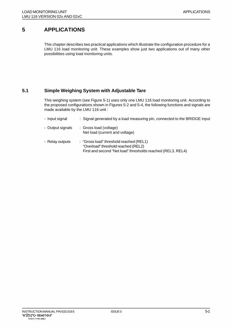
5 APPLICATIONS
This chapter describes two practical applications which illustrate the configuration procedure for aLMU 116 load monitoring unit. These examples show just two applications out of many otherpossibilities using load monitoring units.
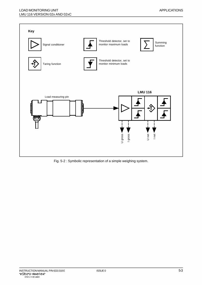
5.1 Simple Weighing System with Adjustable Tare
This weighing system (see Figure 5-1) uses only one LMU 116 load monitoring unit. According tothe proposed configurations shown in Figures 5-2 and 5-4, the following functions and signals aremade available by the LMU 116 unit :
- Input signal : Signal generated by a load measuring pin, connected to the BRIDGE input
- Output signals : Gross load (voltage)Net load (current and voltage)
- Relay outputs : “Gross load” threshold reached (REL1)“Overload” threshold reached (REL2)First and second “Net load” thresholds reached (REL3, REL4)

APPLICATIONS LOAD MONITORING UNITLMU 116 VERSION 02x AND 02xC
5-2 ISSUE 0 INSTRUCTION MANUAL P/N 633.018 E
Fig. 5-1 : Example of a simple weighing system used with lifting devices.
Loadmeasuring pin
LOAD MONITORING UNIT APPLICATIONSLMU 116 VERSION 02x AND 02xC
INSTRUCTION MANUAL P/N 633.018 E ISSUE 0 5-3
Summingfunction
Threshold detector, set tomonitor maximum loads
Threshold detector, set tomonitor minimum loads
Signal conditioner
Taring function
Fig. 5-2 : Symbolic representation of a simple weighing system.
Key
Load measuring pin
LMU 116
U g
ross
I gr
oss
U n
et
I ne
t
APPLICATIONS LOAD MONITORING UNITLMU 116 VERSION 02x AND 02xC
5-4 ISSUE 0 INSTRUCTION MANUAL P/N 633.018 E
Net
load
(vol
tage
)
1st
Thr
esho
ld"N
et lo
ad"
1st
Thr
esho
ld"N
et lo
ad"
1st
Thr
esho
ld"N
et lo
ad"
Initi
aliz
atio
n
2nd
Thr
esho
ld"N
et lo
ad"
2 nd
Thr
esho
ld"N
et lo
ad"
2 nd
Thr
esho
ld"N
et lo
ad"
Initi
aliz
atio
n
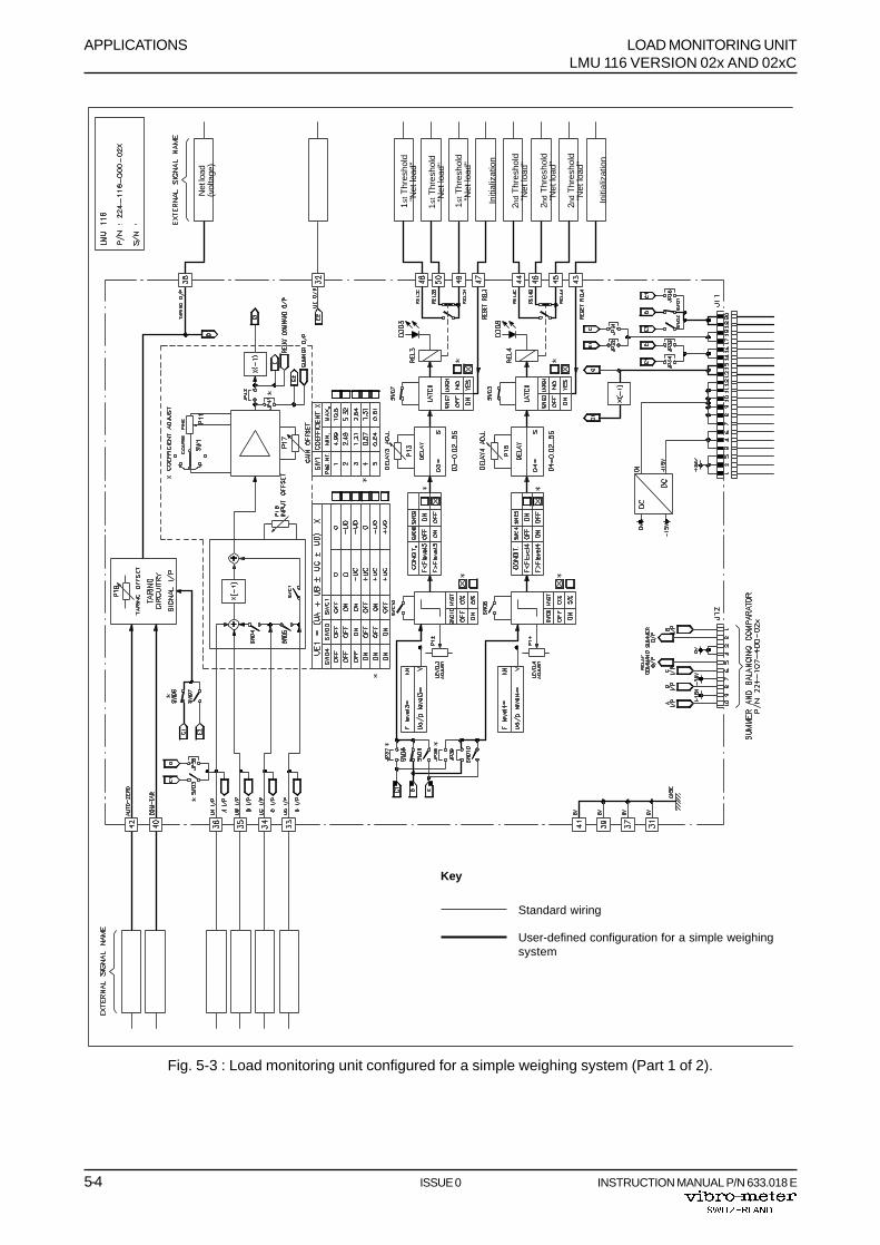
Fig. 5-3 : Load monitoring unit configured for a simple weighing system (Part 1 of 2).
Key
User-defined configuration for a simple weighingsystem
Standard wiring
LOAD MONITORING UNIT APPLICATIONSLMU 116 VERSION 02x AND 02xC
INSTRUCTION MANUAL P/N 633.018 E ISSUE 0 5-5
Thr
esho
ld"O
verla
od"
Thr
esho
ld"O
verla
od"
Thr
esho
ld"O
verla
od"
Thr
esho
ld"G
ross
load
"
Thr
esho
ld"G
ross
load
"
Thr
esho
ld"G
ross
load
"
Gro
ss lo
ad(v
olta
ge)
Gro
ss lo
ad(0
V)
Gro
ss lo
ad(c
urre
nt)
Gro
ss lo
ad(0
V)
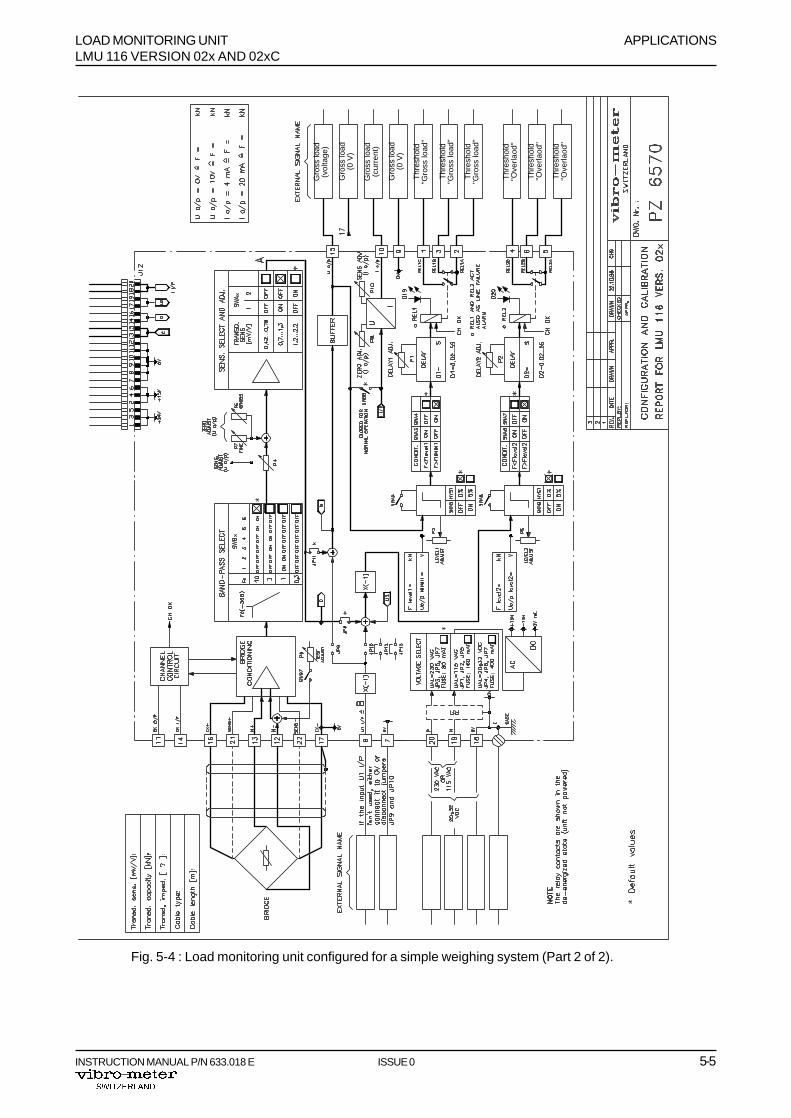
Fig. 5-4 : Load monitoring unit configured for a simple weighing system (Part 2 of 2).

APPLICATIONS LOAD MONITORING UNITLMU 116 VERSION 02x AND 02xC
5-6 ISSUE 0 INSTRUCTION MANUAL P/N 633.018 E
Fig. 5-5 : Example of multi-transducer weighing system for container loading bridges.
Loadmeasuring pin
AB
D
C
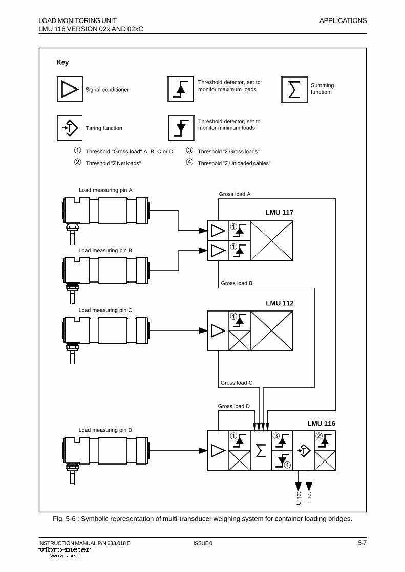
5.2 Multi-Transducer Weighing System for Container Loading Bridges
This weighing system (see Figure 5-5) uses an LMU 116, an LMU 117 and an LMU 112 loadmonitoring unit. According to the proposed configuration shown in Figures 5-6 and 5-8, the followingfunctions and signals are available on the LMU 116 unit :
- Input signal : Signal originating from load measuring pin D, connected to the LMU 116BRIDGE inputGross load D, from the LMU 116Gross loads A and B, from the LMU 117Gross load C, from the LMU 112
- Output signals : Net load sum (current and voltage)Gross load D (voltage)
- Relay outputs : Threshold “Gross load D” reached (REL1)Threshold “Σ Gross loads” reached (REL3)
Threshold “Σ Unloaded cable” reached (REL4)
Threshold “Σ Net loads” reached (REL2)
LOAD MONITORING UNIT APPLICATIONSLMU 116 VERSION 02x AND 02xC
INSTRUCTION MANUAL P/N 633.018 E ISSUE 0 5-7
Summingfunction
Threshold detector, set tomonitor maximum loads
Threshold detector, set tomonitor minimum loads
Signal conditioner
Taring function
Fig. 5-6 : Symbolic representation of multi-transducer weighing system for container loading bridges.
Key
Load measuring pin A
U n
et
I ne
t
Load measuring pin B
Load measuring pin C
Load measuring pin DLMU 116
LMU 112
LMU 117
Gross load A
Gross load B
Gross load D
Gross load C
À
À
À
À ÁÂ
Ã
À Threshold "Gross load" A, B, C or D Â Threshold "Σ Gross loads"
Á Threshold "Σ Net loads" Ã Threshold "Σ Unloaded cables"
APPLICATIONS LOAD MONITORING UNITLMU 116 VERSION 02x AND 02xC
5-8 ISSUE 0 INSTRUCTION MANUAL P/N 633.018 E
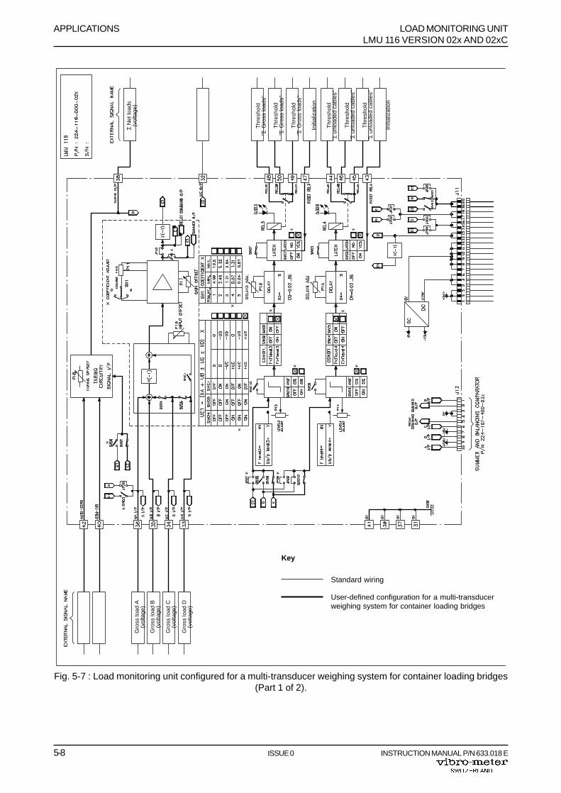
Fig. 5-7 : Load monitoring unit configured for a multi-transducer weighing system for container loading bridges(Part 1 of 2).
Σ N
et lo
ads
(vol
tage
)
Thr
esho
ld"Σ
Gro
ss lo
ads"
Thr
esho
ld"Σ
Gro
ss lo
ads"
Thr
esho
ld"Σ
Gro
ss lo
ads"
Initi
aliz
atio
n
Thr
esho
ld"Σ
unl
oade
d ca
bles
"
Thr
esho
ld"Σ
unl
oade
d ca
bles
"
Thr
esho
ld"Σ
unl
oade
d ca
bles
"
Initi
aliz
atio
n
Gro
ss lo
ad A
(vol
tage
)
Gro
ss lo
ad B
(vol
tage
)
Gro
ss lo
ad C
(vol
tage
)
Gro
ss lo
ad D
(vol
tage
)
Key
User-defined configuration for a multi-transducerweighing system for container loading bridges
Standard wiring
LOAD MONITORING UNIT APPLICATIONSLMU 116 VERSION 02x AND 02xC
INSTRUCTION MANUAL P/N 633.018 E ISSUE 0 5-9
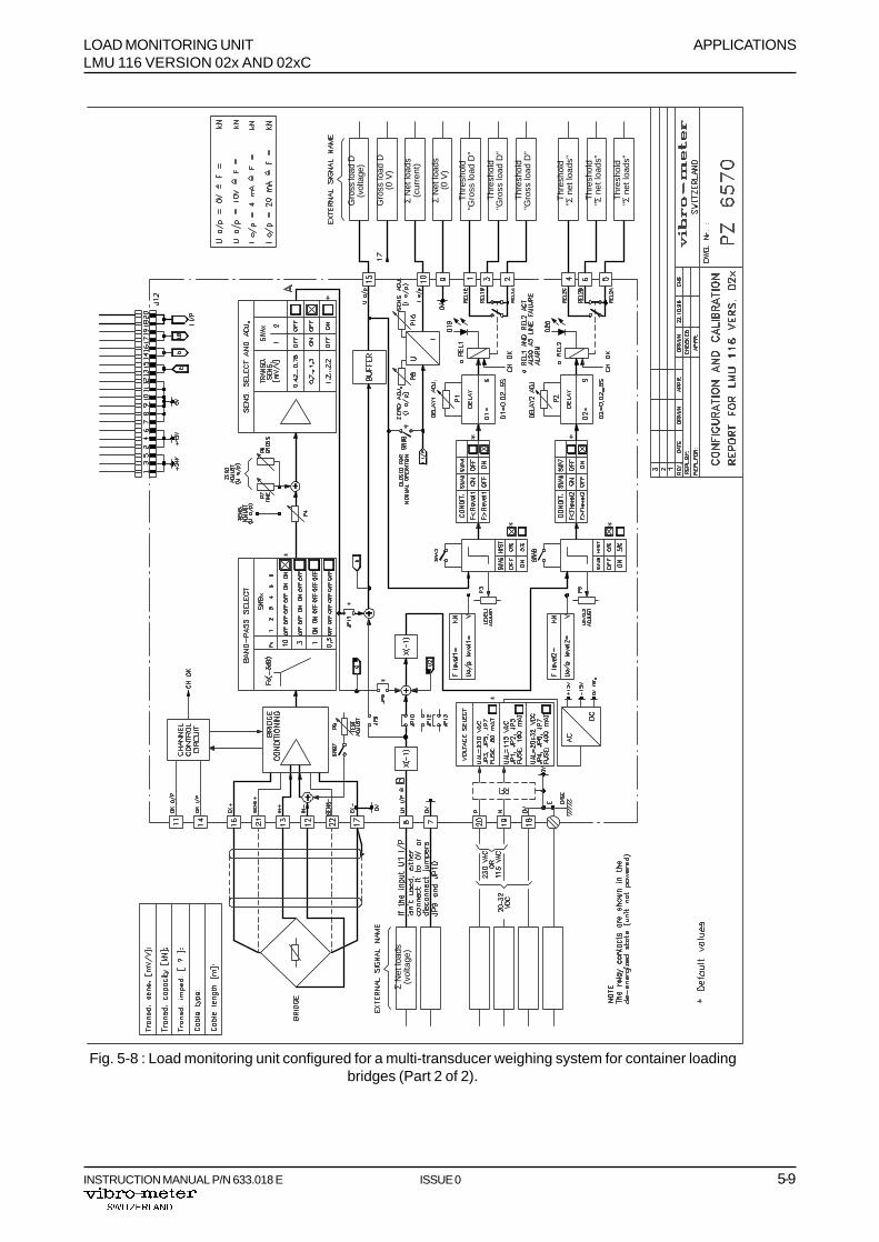
Fig. 5-8 : Load monitoring unit configured for a multi-transducer weighing system for container loadingbridges (Part 2 of 2).
Thr
esho
ld"Σ
net
load
s"
Thr
esho
ld"Σ
net
load
s"
Thr
esho
ld"Σ
net
load
s"
Thr
esho
ld"G
ross
load
D"
Thr
esho
ld"G
ross
load
D"
Thr
esho
ld"G
ross
load
D"
Gro
ss lo
ad D
(vol
tage
)
Gro
ss lo
ad D
(0 V
)Σ
Net
load
s(v
olta
ge)
Σ N
et lo
ads
(cur
rent
)
Σ N
et lo
ads
(0 V
)

APPLICATIONS LOAD MONITORING UNITLMU 116 VERSION 02x AND 02xC
5-10 ISSUE 0 INSTRUCTION MANUAL P/N 633.018 E
THIS PAGE INTENTIONALLY LEFT BLANK

LOAD MONITORING UNIT APPENDIX ALMU 116 VERSION 02x AND 02xC MECHANICAL DRAWING
INSTRUCTION MANUAL P/N 633.018 E ISSUE 0 A-1
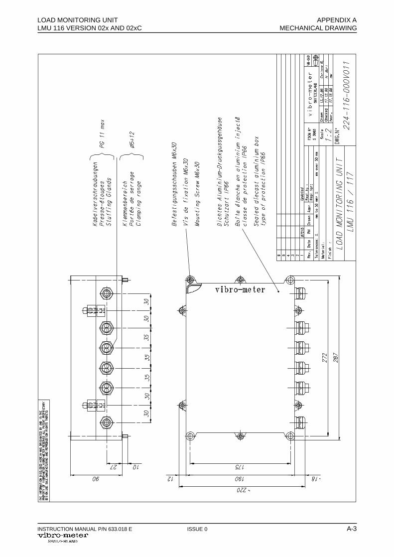
A MECHANICAL DRAWING
Designation Drawing No.
- LMU 116/117 Load Monitoring Unit 224-116-000 V 011

APPENDIX A LOAD MONITORING UNITMECHANICAL DRAWING LMU 116 VERSION 02x AND 02xC
A-2 ISSUE 0 INSTRUCTION MANUAL P/N 633.015 E
THIS PAGE INTENTIONALLY LEFT BLANK
LOAD MONITORING UNIT APPENDIX ALMU 116 VERSION 02x AND 02xC MECHANICAL DRAWING
INSTRUCTION MANUAL P/N 633.018 E ISSUE 0 A-3

APPENDIX A LOAD MONITORING UNITMECHANICAL DRAWING LMU 116 VERSION 02x AND 02xC
A-4 ISSUE 0 INSTRUCTION MANUAL P/N 633.015 E
THIS PAGE INTENTIONALLY LEFT BLANK

LOAD MONITORING UNIT APPENDIX BLMU 116 VERSION 02x AND 02xC CONFIGURATION AND CALIBRATION FORM
INSTRUCTION MANUAL P/N 633.018 E ISSUE 0 B-1
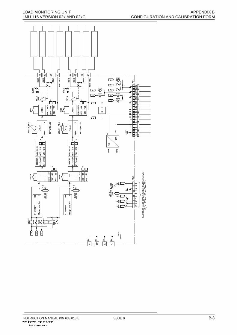
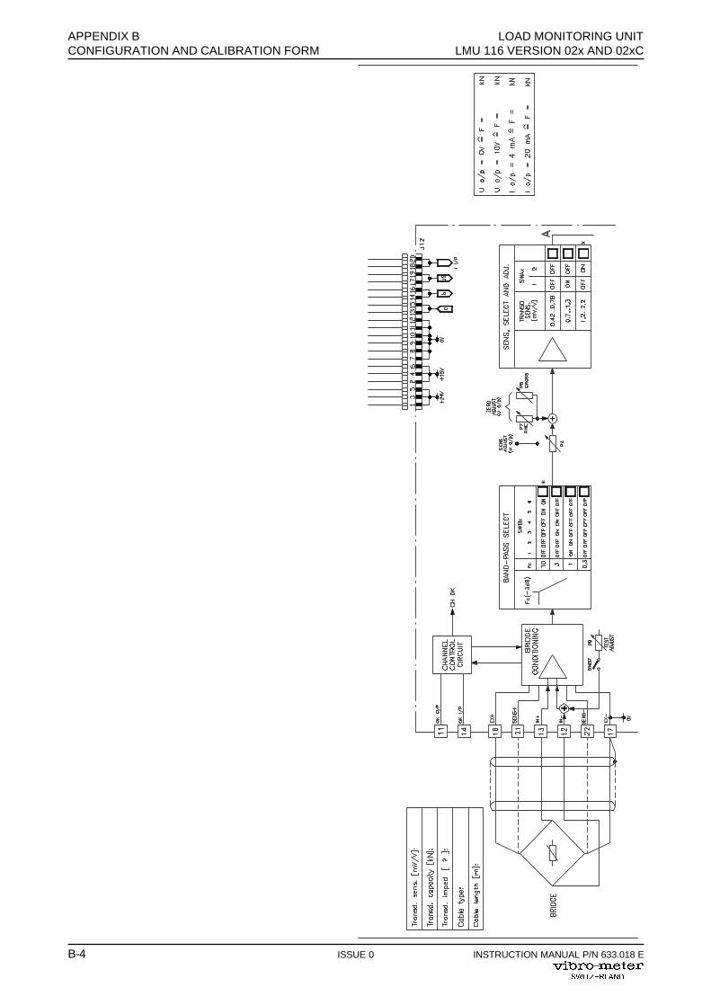
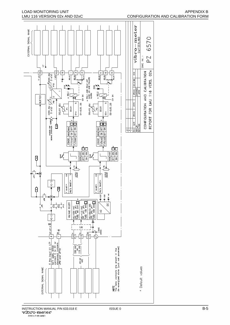
B CONFIGURATION AND CALIBRATION FORM
Configuration and calibration form PZ 6494 contained in this appendix must be duly completed bythe user in accordance with the information given in Chapter 3 of this manual and placed inside theload monitor under the cover.
One copy of this must be returned to the address indicated below so that the after-sales service forthe unit is assured on the best conditions :
Vibro-Meter SAInstrumentation After-Sales Service
Route de Moncor 4
CH-1701 Fribourg

APPENDIX B LOAD MONITORING UNITCONFIGURATION AND CALIBRATION FORM LMU 116 VERSION 02x AND 02xC
B-2 ISSUE 0 INSTRUCTION MANUAL P/N 633.018 E
LOAD MONITORING UNIT APPENDIX BLMU 116 VERSION 02x AND 02xC CONFIGURATION AND CALIBRATION FORM
INSTRUCTION MANUAL P/N 633.018 E ISSUE 0 B-3
APPENDIX B LOAD MONITORING UNITCONFIGURATION AND CALIBRATION FORM LMU 116 VERSION 02x AND 02xC
B-4 ISSUE 0 INSTRUCTION MANUAL P/N 633.018 E
LOAD MONITORING UNIT APPENDIX BLMU 116 VERSION 02x AND 02xC CONFIGURATION AND CALIBRATION FORM
INSTRUCTION MANUAL P/N 633.018 E ISSUE 0 B-5

APPENDIX B LOAD MONITORING UNITCONFIGURATION AND CALIBRATION FORM LMU 116 VERSION 02x AND 02xC
B-6 ISSUE 0 INSTRUCTION MANUAL P/N 633.018 E
THIS PAGE INTENTIONALLY LEFT BLANK

LOAD MONITORING UNIT APPENDIX CLMU 116 VERSION 02x AND 02xC DECLARATION OF EC CONFORMITY
INSTRUCTION MANUAL P/N 633.018 E ISSUE 0 C-1
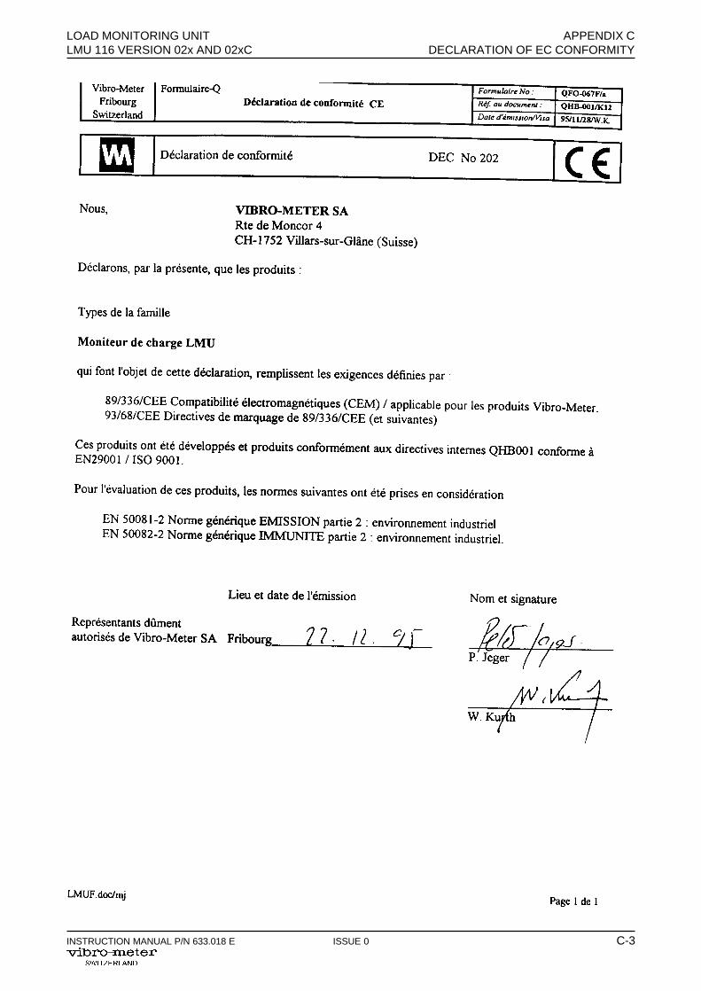
C DECLARATION OF EC CONFORMITY
Designation No. Reference
Declaration of conformity DEC No 202 QHB-001/K12

APPENDIX C LOAD MONITORING UNITDECLARATION OF EC CONFORMITY LMU 116 VERSION 02x AND 02xC
C-2 ISSUE 0 INSTRUCTION MANUAL P/N 633.018 E
THIS PAGE INTENTIONALLY LEFT BLANK
LOAD MONITORING UNIT APPENDIX CLMU 116 VERSION 02x AND 02xC DECLARATION OF EC CONFORMITY
INSTRUCTION MANUAL P/N 633.018 E ISSUE 0 C-3

APPENDIX C LOAD MONITORING UNITDECLARATION OF EC CONFORMITY LMU 116 VERSION 02x AND 02xC
C-4 ISSUE 0 INSTRUCTION MANUAL P/N 633.018 E
THIS PAGE INTENTIONALLY LEFT BLANK

PRODUCT DEFECT REPORT
If you should observe any problems with this Vibro-Meter product would you please contactyour Vibro-Meter agent .Please fill in this form (in English) , giving as much specific information as possible on theproblems observed. This will enable us to decide the quickest way to solve the problem.NB : If more than one unit is defective, photocopy this sheet and fill in one copy for each unit.
THIS REPORT OR A COPY OF IT SHOULD ACCOMPANY THE DEFECTIVEUNIT AT ALL TIMES !
Module type : ___________________________________
Part number (P/N) : _______________________________
Serial number (S/N) : _____________________________
Vibro-Meter order no. : ___________________________
Date of purchase : _______________________________
Site where used : ________________________________
(Please continue on back of sheet if necessary)
In case we need any further information, please provide us with the name of an employeewith whom we can make contact :
Is the problem :
Always evident ? Intermittent ?
Temperature dependent ? ( Mark as appropriate)
Name : ______________________________________________________
Department : _________________________________________________
Company : ___________________________________________________
Address : _________________________________________________
_________________________________________________
_________________________________________________
Country : _________________________ Postal code : _______________
Tel. : ____________________________ Telex : ____________________
Fax : ___________________________
Signature : ______________________ Date : _______________________
Ple
ase
cut o
ut o
r co
py a
nd s
end
to V
ibro
-Met
er S
ales
age
nt
NB : For plug-inmodules this infor-mation can usually befound on the labelstuck on its side.
- -
- -
- -
- -
- -
- -
- -
- -
- -
- -
- -
- -
- -
- -
- -
- -
- -
- -
- -
- -
- -
- -
- -
- -
- -
- -
- -
- -
- -
- -
- -
- -
- -
- -
- -
- -
- -
- -
- -
- -
- -
- -
- -
- -
-
Problems observed : ________________________________________________________
____________________________________________________________________________
_____________________________________________________________________________
________________________________________________________________________________
______________________________________________________________________________________
______________________________________________________________________________________
_______________________________________________________________________________

PRODUCT DEFECT REPORT(cont.)
Please use this space for any additional information :

- - - - - - - - - - - - - - - - - - - - - - - - - - - - - - - - - - - - - - - - - - - - - - - - - - - - - - - - - - - - - - - -
DOCUMENTATION EVALUATION FORM
Vibro-Meter welcomes your evaluation of this intruction manual. Your comments andsuggestions will help us to improve our documentation.
Please circle the following Yes or No :
• Is the document well organized ? Yes No
• Is the information technically accurate ? Yes No
• Would you like more technical detail ? Yes No
• Are the instructions clear and complete ? Yes No
• Are the descriptions easy to understand ? Yes No
• Are the examples and diagrams/photos helpful ? Yes No
• Are there enough examples and diagrams/photos ? Yes No
• Is the style/wording easy to read ? Yes No
• Are there any omissions ? Yes No(If so, please list below)
Instruction Manual : P/N :
Please cut out and mail to Vibro-Meter Thank you for your cooperation- -
- -
- -
- -
- -
- -
- -
- -
- -
- -
- -
- -
- -
- -
- -
- -
- -
- -
- -
- -
- -
- -
- -
- -
- -
- -
- -
- -
- -
- -
- -
- -
- -
- -
- -
- -
- -
- -
- -
- -
- -
- -
- -
- -
- -
-
Name : _______________________________________________________
Title : ________________________________________________________
Company : ___________________________________________________
Address : ___________________________________________________
___________________________________________________
___________________________________________________
Country : ___________________________ Postal code : _____________
Signature : _________________________ Date : ____________________
Comments : _____________________________________________________________
________________________________________________________________________
________________________________________________________________________
________________________________________________________________________
________________________________________________________________________
________________________________________________________________________
________________________________________________________________________
LOAD MONITORING UNIT 633.018 ELMU 116 VERSIONS 02x AND 02xC
Tape hereTape
her
e
Vibro-Meter SARoute de Moncor 4CH-1701 FribourgSwitzerland
Attn : Technical Documentation Dept. ( I / M )
Placestamphere
Tape here Please do not staple Tape here
- - - - - - - - - - - - - - - - - - - - - - - - - - - - - - - - - - - - - - - - - - - - - - - - - - - - - - - - - -Fold here