instruction manual model 1300 - ensesa
TRANSCRIPT

Instruction Manual
Model 1300 (Model A9)
Retrievable Extensometer
No part of this instruction manual may be reproduced, by any means, without the written consent of Geokon, Inc.
The information contained herein is believed to be accurate and reliable. However, Geokon, Inc. assumes no
responsibility for errors, omissions or misinterpretation. The information herein is subject to change without
notification.
Copyright © 1995,1996, 2004, 2007, 2009, 2011 by Geokon, Inc.
(Doc. REV G. 8/11)


Warranty Statement
Geokon, Inc. warrants its products to be free of defects in materials and workmanship, under
normal use and service for a period of 13 months from date of purchase. If the unit should
malfunction, it must be returned to the factory for evaluation, freight prepaid. Upon examination
by Geokon, if the unit is found to be defective, it will be repaired or replaced at no charge.
However, the WARRANTY is VOID if the unit shows evidence of having been tampered with or
shows evidence of being damaged as a result of excessive corrosion or current, heat, moisture or
vibration, improper specification, misapplication, misuse or other operating conditions outside of
Geokon's control. Components which wear or which are damaged by misuse are not warranted.
This includes fuses and batteries.
Geokon manufactures scientific instruments whose misuse is potentially dangerous. The
instruments are intended to be installed and used only by qualified personnel. There are no
warranties except as stated herein. There are no other warranties, expressed or implied, including
but not limited to the implied warranties of merchantability and of fitness for a particular purpose.
Geokon, Inc. is not responsible for any damages or losses caused to other equipment, whether
direct, indirect, incidental, special or consequential which the purchaser may experience as a
result of the installation or use of the product. The buyer's sole remedy for any breach of this
agreement by Geokon, Inc. or any breach of any warranty by Geokon, Inc. shall not exceed the
purchase price paid by the purchaser to Geokon, Inc. for the unit or units, or equipment directly
affected by such breach. Under no circumstances will Geokon reimburse the claimant for loss
incurred in removing and/or reinstalling equipment.
Every precaution for accuracy has been taken in the preparation of manuals and/or software,
however, Geokon, Inc. neither assumes responsibility for any omissions or errors that may appear
nor assumes liability for any damages or losses that result from the use of the products in
accordance with the information contained in the manual or software.


TABLE of CONTENTS
1. INTRODUCTION ..................................................................................................................................................1
1.1. THEORY OF OPERATION......................................................................................................................................1
2. INSTALLATION ....................................................................................................................................................1
2.1. PRELIMINARY TESTS..........................................................................................................................................2 2.2. EXTENSOMETER INSTALLATION .........................................................................................................................2 2.3. CABLE SPLICING.................................................................................................................................................4 2.4. INITIAL READINGS .............................................................................................................................................4 2.5. ELECTRICAL NOISE.............................................................................................................................................4
3. TAKING READINGS............................................................................................................................................5
3.1. OPERATION OF THE GK-401 READOUT BOX......................................................................................................5 3.2. OPERATION OF THE GK-403 READOUT BOX......................................................................................................5 3.3. OPERATION OF THE GK404 READOUT BOX .......................................................................................................5 3.4. MEASURING TEMPERATURES.............................................................................................................................6
4. DATA REDUCTION .............................................................................................................................................6
4.1 DIGITS .................................................................................................................................................................6 4.2. TEMPERATURE CORRECTION .............................................................................................................................9
5. TROUBLESHOOTING.......................................................................................................................................11
APPENDIX A - SPECIFICATIONS ......................................................................................................................12
APPENDIX B - THERMISTOR TEMPERATURE DERIVATION ...................................................................13
APPENDIX C - ANCHOR PULL OUT TEST RESULTS ....................................................................................14
APPENDIX D - SWAGELOK FITTING ASSEMBLY INSTRUCTIONS..........................................................15

LIST of FIGURES and TABLES
FIGURE 1 - MODEL A-9 RETRIEVABLE EXTENSOMETER ANCHOR ................................................................................. 1 FIGURE 2 - MODEL A-9 INSTALLATION ......................................................................................................................... 3 TABLE 1 - ENGINEERING UNITS CONVERSION MULTIPLIERS ......................................................................................... 7 FIGURE 3 TYPICAL CALIBRATION SHEET ....................................................................................................................... 8 TABLE 2 - THERMAL COEFFICIENT CALCULATION CONSTANTS .................................................................................... 9 TABLE 3. THERMAL COEFFICIENTS OF EXPANSION FOR VARIOUS ROD MATERIALS ..................................................... 10 TABLE A-1 MODEL A-9 TRANSDUCER SPECIFICATIONS.............................................................................................. 12 TABLE B-1 THERMISTOR RESISTANCE VERSUS TEMPERATURE .................................................................................. 13 FIGURE C-1 ANCHOR PULL OUT TEST RESULTS......................................................................................................... 14

1
1. INTRODUCTION
1.1. Theory of Operation The Geokon Model A-9 Retrievable Extensometer is designed primarily for short term measurements of deformation in boreholes in concrete, rock, etc. The system is used in both precast and cast-in-place concrete piles in plate load tests in rock and anywhere where deformations need to be measured in boreholes, either drilled or cast in to the structure being analyzed. The system consists of pneumatically actuated anchors with spring loaded transducers that are connected to one another in series by a single connecting rod. When installed, the anchors are fixed in place and the transducers measure the deformation between the anchor positions. The connecting rods are held in tension to eliminate errors due to bowing and friction. Connecting rods of fiberglass, graphite epoxy, and stainless steel are available. The standard system is designed to be used in a nominal 2" ID pipe; either plastic or steel.
Anchor
Transducer
Transducer Shaft
Swagelok for Connecting Rod
Nylon Inflation Line
Pistons (8 places)Transducer Cable
Cable & Tube Slot (4 places)
Connecting Rod
Top View
2.0"51 mm
16.875"429 mm
Figure 1 - Model A-9 Retrievable Extensometer Anchor
2. INSTALLATION

2
2.1. Preliminary Tests
Before assembly and installation of the extensometer the transducers should be checked for proper operation. See Section 3 for readout instructions. In position "B" of the GK-401, GK-403 and GK-404 Readouts the gage will read between 2000 and 2500. The transducer may need to be slightly extended to get a reading. Pull on the Swagelok affixed to the transducer shaft to do this (see Figure 1).
Checks of electrical continuity can also be made using an ohmmeter. Resistance between the gage leads should be approximately 180, ±10. Remember to add cable resistance when checking (22 AWG stranded copper leads are approximately 14.7/1000' or 48.5/km, multiply by 2 for both directions). Between the green and white should be approximately 3000 ohms at 25° (see Table B-1), and between any conductor and the shield or the case of the sensor should exceed 2 megohms.
Checks on the actuation of the anchor pistons must be done with care. The anchor must first be positioned inside a piece of pipe or tubing with an inside diameter of approximately 50mm(2 inch), before the pistons are actuated by pneumatic pressure. If the pneumatic pressure is applied to the pistons while the anchor is not inside a tube, the pistons will over-range and in the process the O-ring seals will be damaged and the pistons will then be unable to hold pneumatic pressure without leaking
2.2. Extensometer Installation
If the transducers check out the assembly can proceed.
An adequate area must be located for the assembly of the extensometer. Preferably it should be as long as the extensometer, clear of debris and obstructions. When assembling the extensometer in the field be especially careful to keep dirt out of the Swagelok fittings for the inflation lines.

ManifoldPressure Supply
Transducer
Anchor
Inflation Lines
Connecting Rod
Bottom Anchor
PVC Pipe
Regulator
geokon
30'
10'
5'
5'
5'
Well Casing
Transducer Cables
Position #1
Position #2
Position #3
Position #4
Position #5
3 1. Determine the anchor positions, i.e. the
depth or position in the borehole for each anchor. Starting with the bottom, or deepest, anchor calculate the distance between it and the second anchor; this is the increment over which the measurement will be made. The connecting rod must now be cut to the proper length to make up this increment. For the standard 25 mm (1") transducer positioned at mid-range the length of the transducer assembly is 492 mm (19.375"). This length must be deducted from the increment length in order to make the correct rod length. For example, if the increment length is 3 meters the rod length is 2.508 meters (3.0 - 0.492). Calculate the rod lengths for all anchor positions and cut rods to length. Be careful when cutting the fiberglass rod that it does not splinter. Use a file to deburr the edges.
2. Connect the rod to the Swagelok fitting on
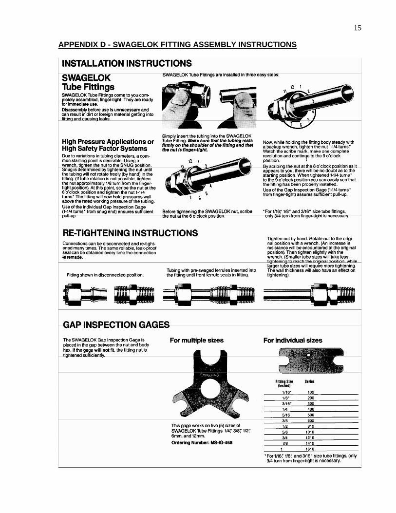
the bottom anchor, pushing it in until it hits the shoulder. Tighten the Swagelok finger tight, then an additional 7 flats (1¼ turns). Use two wrenches to do this, one on the Swagelok nut, the other on the body. See Appendix D for additional Swagelok fitting assembly instructions.
Connect the other end of the rod to the Swagelok fitting on the first transducer assembly using the same two wrenches. Repeat this for all the rods and sensors, leaving the instrument cables rolled up.
Finally, attach an appropriate length of rod to the top anchor, this will allow for installation and removal of the system.
3. Cut nylon inflation tubing for each anchor
position. Allow enough tubing to connect to the pressure manifold. Attach to the Swagelok fitting for the inflation line.
Figure 2 - Model A-9 Installation Finger tighten and then turn an additional 7 flats (1¼ turns) to engage the ferrule. See
Appendix D for additional Swagelok fitting assembly instructions. 4. Lay out all the transducer cables and inflation lines next to the anchors and attached rods.
Position the lines and cables in the slots of the anchors and tape on either side of the anchors,

4 i.e. tape above the anchor around the connecting rod and below the anchor around the transducer body. Continue this procedure at each anchor position from the deepest up to the top. Be sure the inflation lines and transducer cables are clearly labeled. Allow enough slack, at least the range of the instrument, (25mm, 1") between anchor positions for the movement of the anchors.
5. The assembly is now ready for installation in the borehole. Lower into the borehole with the
bottom anchor first. Bend the connecting rod through a large arc, as needed to lower the extensometer. Be careful not to permanently bend the rods.
6. Once the assembly is installed attach the inflation lines to the pressure manifold. Attach the
transducer cables to the terminal box or multiplexer. 7. Make sure all the valves of the pressure manifold are in the off position. Attach the air
supply to the pressure manifold. Carbon dioxide, compressed air or nitrogen may be used for the pressure supply. The recommended pressure for setting the extensometer is 300 psi (20 bar). Appendix C illustrates the relationship between applied pressure and pull-out of the anchor. The maximum recommended applied pressure is 750 psi (50 bar).
8. Turn on the air for the deepest position of the extensometer. Attach the readout to the
instrument cable from the first transducer position. To set the transducer anchor pull on the extension rod coming out of the borehole until the desired reading is obtained and then turn on the valve for that position. To set the instrument at mid-range the reading should be around 5000 digits. To measure mostly tensile strains the reading should be around 3000. To measure mostly compressive strains the reading should be around 7000. Repeat this procedure for each transducer position of the extensometer. Installation complete.
2.3. Cable Splicing Cables may be spliced to lengthen them, without affecting gage readings. Always waterproof the splice completely, preferably using an epoxy based splice kit such the 3M Scotchcast, model 82-A1. These kits are available from the factory. When making splices, use solder connections wherever feasible or crimp connectors if not.
2.4. Initial Readings All readings are referred to an initial reading so it is important that this initial reading be carefully taken. Conditions should be noted at the time of all readings, especially during curing, i.e., temperature, time after placement, local conditions, etc.
2.5. Electrical Noise Care should be exercised when installing instrument cables to keep them as far away as possible from sources of electrical interference such as power lines, generators, motors, transformers, arc welders, etc. Cables should never be buried or run with AC power lines! The instrument cables will pick up the 50 or 60 Hz (or other frequency) noise from the power cable and this will likely cause a problem obtaining a stable reading.
5
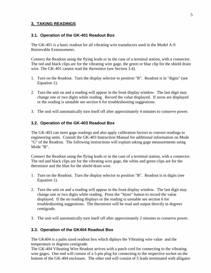
3. TAKING READINGS
3.1. Operation of the GK-401 Readout Box The GK-401 is a basic readout for all vibrating wire transducers used in the Model A-9 Retrievable Extensometer. Connect the Readout using the flying leads or in the case of a terminal station, with a connector. The red and black clips are for the vibrating wire gage, the green or blue clip for the shield drain wire. The GK-401 cannot read the thermistor (see Section 3.4). 1. Turn on the Readout. Turn the display selector to position "B". Readout is in "digits" (see
Equation 1). 2. Turn the unit on and a reading will appear in the front display window. The last digit may
change one or two digits while reading. Record the value displayed. If zeros are displayed or the reading is unstable see section 6 for troubleshooting suggestions.
3. The unit will automatically turn itself off after approximately 4 minutes to conserve power.
3.2. Operation of the GK-403 Readout Box The GK-403 can store gage readings and also apply calibration factors to convert readings to engineering units. Consult the GK-403 Instruction Manual for additional information on Mode "G" of the Readout. The following instructions will explain taking gage measurements using Mode "B". Connect the Readout using the flying leads or in the case of a terminal station, with a connector. The red and black clips are for the vibrating wire gage, the white and green clips are for the thermistor and the blue for the shield drain wire. 1. Turn on the Readout. Turn the display selector to position "B". Readout is in digits (see
Equation 1). 2. Turn the unit on and a reading will appear in the front display window. The last digit may
change one or two digits while reading. Press the "Store" button to record the value displayed. If the no reading displays or the reading is unstable see section 6 for troubleshooting suggestions. The thermistor will be read and output directly in degrees centigrade.
3. The unit will automatically turn itself off after approximately 2 minutes to conserve power.
3.3. Operation of the GK404 Readout Box The GK404 is a palm sized readout box which diplays the Vibrating wire value and the temperature in degrees centigrade. The GK-404 Vibrating Wire Readout arrives with a patch cord for connecting to the vibrating wire gages. One end will consist of a 5-pin plug for connecting to the respective socket on the bottom of the GK-404 enclosure. The other end will consist of 5 leads terminated with alligator

6 clips. Note the colors of the alligator clips are red, black, green, white and blue. The colors represent the positive vibrating wire gage lead (red), negative vibrating wire gage lead (black), positive thermistor lead (green), negative thermistor lead (white) and transducer cable drain wire (blue). The clips should be connected to their respectively colored leads from the vibrating wire gage cable. Use the POS (Position) button to select position B and the MODE button to select Dg, (digits). Other functions can be selected as described in the GK404 Manual. The GK-404 will continue to take measurements and display the readings until the OFF button is pushed, or if enabled, when the automatic Power-Off timer shuts the GK-404 off. The GK-404 continuously monitors the status of the (2) 1.5V AA cells, and when their combined voltage drops to 2V, the message Batteries Low is displayed on the screen. A fresh set of 1.5V AA batteries should be installed at this point
3.4. Measuring Temperatures The vibrating wire transducers used in the Model A-9 Retrievable Extensometer is equipped with a thermistor for reading temperature. The thermistor gives a varying resistance output as the temperature changes. Usually the white and green leads are connected to the internal thermistor. 1. Connect an ohmmeter to the two thermistor leads coming from the transducer. (Since the
resistance changes with temperature are so large, the effect of cable resistance is usually insignificant.)
2. Look up the temperature for the measured resistance in Table B-1 (Appendix B). Alternately
the temperature could be calculated using Equation B-1 (Appendix B). For example, a resistance of 3400 ohms equivalent to 22° C. When long cables are used the cable resistance may need to be taken into account. Standard 22 AWG stranded copper lead cable is approximately 14.7/1000' or 48.5/km, multiply by 2 for both directions.
Note: The GK-403 and GK-404 readout boxes will read the thermistor and display temperature in C automatically.
4. DATA REDUCTION
4.1 Digits The basic units utilized by Geokon for measurement and reduction of data from the vibrating wire displacement transducers used in the Model A-9 are "digits". The units displayed by the GK-401, GK-402, and GK-403 in position "B" are digits. Calculation of digits is based on the following equation;
DigitsPeriod
2
3110 or Digits
Hz
2
1000
Equation 1 - Digits Calculation

7 To convert digits to deformation the following equation applies;
D = (R1 - R0) G F
Equation 2 - Deformation Calculation Where; D is the calculated deformation. R1 is the current reading. R0 is the initial reading usually obtained at installation (see section 2.4). G is the calibration factor, usually in terms of millimeters or inches per digit taken
from the calibration sheet an example of which is shown in Figure 3 F is an engineering units conversion factor (optional), see Table 1.
From To
Inches
Feet
Millimeters
Centimeters
Meters
Inches 1 12 0.03937 0.3937 39.37 Feet 0.0833 1 0.003281 0.03281 3.281
Millimeters 25.4 304.8 1 10 1000 Centimeters 2.54 30.48 0.10 1 100
Meters 0.0254 0.3048 0.001 0.01 1
Table 1 - Engineering Units Conversion Multipliers
For example, the initial reading (R0) with no load on the pile of a Model A-9 transducer is 5102 digits. The reading with a 100 ton load on the pile, the current reading (R1), is 4523. The calibration factor, G, is 0.0001755 inches/digit. The deformation change is;
D = (4523 5102) 0.0001755 = 0.1016 inches Note that decreasing readings (digits) indicate compression. To calculate strain divide the deformation by the distance between the anchors. For example, if the deformation change between two anchors spaced 12 feet apart was -0.1016 inches. The strain change for that segment of the pile, uncorrected for temperature, would be -0.1016/144 x 10^6 = -706 strain (compression).

8
Figure 3 Typical Calibration sheet
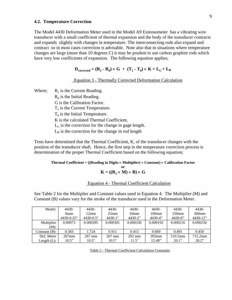
9 4.2. Temperature Correction The Model 4430 Deformation Meter used in the Model A9 Extensometer has a vibrating wire transducer with a small coefficient of thermal expansion and the body of the transducer contracts and expands slightly with changes in temperature. The interconnecting rods also expand and contract so in most cases correction is advisable. Note also that in situations where temperature changes are large (more than 10 degrees C) it may be prudent to use carbon graphite rods which have very low coefficients of expansion. The following equation applies;
Dcorrected = (R1 - R0) G + (T1 - T0) K + LC + LR
Equation 3 - Thermally Corrected Deformation Calculation
Where; R1 is the Current Reading. R0 is the Initial Reading. G is the Calibration Factor. T1 is the Current Temperature. T0 is the Initial Temperature. K is the calculated Thermal Coefficient, LC is the correction for the change in gage length. LR is the correction for the change in rod length Tests have determined that the Thermal Coefficient, K, of the transducer changes with the position of the transducer shaft. Hence, the first step in the temperature correction process is determination of the proper Thermal Coefficient based on the following equation;
Thermal Coefficient = ((Reading in Digits Multiplier) Constant) Calibration Factor or
K = ((R1 M) B) G
Equation 4 - Thermal Coefficient Calculation
See Table 2 for the Multiplier and Constant values used in Equation 4. The Multiplier (M) and Constant (B) values vary for the stroke of the transducer used in the Deformation Meter.
Model: 4430- 6mm
4430-0.25”
4430- 12mm
4430-0.5"
4430- 25mm
4430-1"
4430- 50mm
4430-2"
4430-100mm 4430-4”
4430-150mm 4430-6”
4430-300mm
4430-12” Multiplier
(M): 0.00073 0.000295 0.000301 0.000330 0.000192 0.000216 0.000250
Constant (B): 0.583 1.724 0.911 0.415 0.669 0.491 0.450 Def, Meter
Length (L): 267mm 10.5”
267 mm 10.5"
267 mm 10.5"
292 mm 11.5"
393mm 15.49”
510.5mm 20.1”
715.2mm 28.2”
Table 2 - Thermal Coefficient Calculation Constants

10 The Model 4430 deformation meter length temperature correction (LC) is calculated using Equation 5.
LC = 17.3 10-6 L (T1 - T0) Equation 5 – Deformation Meter Length Correction
Where L is the length of deformation meter in millimeters or inches, (see Table 2), The rod length correction (LR) is calculated from the equation 6
LR = KR S (T1 - T0)
Equation 6 – Rod Length Temperature Correction
Where S is the distance between anchor points minus the length of the transducer in mm or inches and KR is the coeficient of expansion of the rod material from Table 3
Rod Material KRThermal Coefficient
Per º C
Stainless Steel 17.3 x 10⁻⁶
Graphite 0.2 x 10⁻⁶
Fiberglass 6.0 x 10⁻⁶
Table 3. Thermal coefficients of expansion for various rod materials
Example for the same 25mm range transducer as before where the anchor spacing is 144 inches and the rods are fiberglass R1 = 4523 To= 15 degrees C T1 = 30 degrees C S= 144-10.5 = 133.5 inches Then K = [4523 x 0.000301 +0.911] x 0.0001755 = 0.00040 And the total temperature correction (T1-T0) [ K + LC +LR ] = (30 – 15) x [ 0.00040 + 10.5 x 17.3 x10-6 + 133.5 x 6.0 x10-6 ] = +0.0207 inches And the Total deformation, temperature corrected, is -0.1016 + 0.0207 = -0.081 inches and the measured strain is -0.081/144 x 10^6 = - 562 microstrain in compression

11
5. TROUBLESHOOTING Consult the following list of problems and possible solutions should difficulties arise. Consult the factory for additional troubleshooting help. Symptom: Transducer Readings are Unstable
Is the readout box position set correctly? If using a datalogger to record readings automatically are the swept frequency excitation settings correct? Try reading the transducer on a different readout position. For instance, channel A of the GK-401 and GK-403 might be able to read the transducer. To convert the Channel A period display to digits use Equation 1.
Is there a source of electrical noise nearby? Most probable sources of electrical noise are motors, generators, transformers, arc welders and antennas. Make sure the shield drain wire is connected to ground whether using a portable readout or datalogger. If using the GK-401 Readout connect the clip with the green boot to the bare shield drain wire of the pressure cell cable. If using the GK-403 connect the clip with the blue boot to the shield drain wire.
Has the transducer gone outside its range? This may happen in either compression or extension. Check the previous readings for any trends. The extensometer may be need to be re-installed in the borehole, see section 2.
Does the readout work with another transducer? If not, the readout may have a low battery or be malfunctioning. Consult the appropriate readout manual for charging or troubleshooting directions.
Symptom: Transducer Fails to Read
Is the cable cut or crushed? This can be checked with an ohmmeter. Nominal resistance between the two gage leads (usually red and black leads) is 180, 10. Remember to add cable resistance when checking (22 AWG stranded copper leads are approximately 14.7/1000' or 48.5/km, multiply by 2 for both directions). If the resistance reads infinite, or very high (megohms), a cut wire must be suspected. If the resistance reads very low (100) a short in the cable is likely.
Does the readout or datalogger work with another transducer? If not, the readout or datalogger may be malfunctioning. Consult the readout or datalogger manual for further direction.
Sympton: Transducer will not hold pressure Check all the fittings on the pneumatic lines using a soap solution and observe for bubbles. If no leaks are found then the O-ring on the anchor piston may be cut or nicked. Replace the O-ring using one of the spares from the accessories supplied with the equipment. The piston is held inside the anchor by a small “ding” made by a prick punch. This has to be filed off with a round file so that the piston can be pushed out. Replace the O-ring and then push the piston back into place and again “ding” the end of the hole with a hammer and screwdriver so that the piston is once again held in place.

12 APPENDIX A - SPECIFICATIONS A.1. Model A-9 Retrievable Extensometer Transducer
Ranges Available:1 12, 25, 50 mm 0.5, 1, 2"
Overrange: 100% (none) Accuracy: 0.1% (with polynomial expression)
Resolution: 0.025% FSR Linearity: 0.25% FSR
Thermal Zero Shift: < 0.05% FSR/°C Stability: < 0.2%/yr (under static conditions)
Temperature Range: -40 to +60°C -40 to 120° F
Frequency Range: 1200 - 2800 Hz Coil Resistance: 180 , 10
Cable Type:2 2 twisted pair (4 conductor) 22 AWG Foil shield, PVC jacket, nominal OD=4.8 mm (0.1875")
Weight:
1 kg. 2.2 lbs.
Rod Types: Stainless steel, fiberglass, graphite
Table A-1 Model A-9 Transducer Specifications Notes: 1 Consult the factory for other ranges available. 2 Consult the factory for alternate cable types. A.2 Thermistor (see Appendix B also) Range: -80 to +150° C Accuracy: ±0.5° C

13
APPENDIX B - THERMISTOR TEMPERATURE DERIVATION Thermistor Type: YSI 44005, Dale #1C3001-B3, Alpha #13A3001-B3 Resistance to Temperature Equation:
TA B LnR C LnR
1
273 23( ) ( ).
Equation B-1 Convert Thermistor Resistance to Temperature
Where; T Temperature in C. LnR Natural Log of Thermistor Resistance A 1.4051 10-3 (coefficients calculated over the 50 to +150 C. span) B 2.369 10-4 C 1.019 10-7
Ohms Temp Ohms Temp Ohms Temp Ohms Temp Ohms Temp 201.1K -50 16.60K -10 2417 30 525.4 70 153.2 110 187.3K -49 15.72K -9 2317 31 507.8 71 149.0 111 174.5K -48 14.90K -8 2221 32 490.9 72 145.0 112 162.7K -47 14.12K -7 2130 33 474.7 73 141.1 113 151.7K -46 13.39K -6 2042 34 459.0 74 137.2 114 141.6K -45 12.70K -5 1959 35 444.0 75 133.6 115 132.2K -44 12.05K -4 1880 36 429.5 76 130.0 116 123.5K -43 11.44K -3 1805 37 415.6 77 126.5 117 115.4K -42 10.86K -2 1733 38 402.2 78 123.2 118 107.9K -41 10.31K -1 1664 39 389.3 79 119.9 119 101.0K -40 9796 0 1598 40 376.9 80 116.8 120 94.48K -39 9310 1 1535 41 364.9 81 113.8 121 88.46K -38 8851 2 1475 42 353.4 82 110.8 122 82.87K -37 8417 3 1418 43 342.2 83 107.9 123 77.66K -36 8006 4 1363 44 331.5 84 105.2 124 72.81K -35 7618 5 1310 45 321.2 85 102.5 125 68.30K -34 7252 6 1260 46 311.3 86 99.9 126 64.09K -33 6905 7 1212 47 301.7 87 97.3 127 60.17K -32 6576 8 1167 48 292.4 88 94.9 128 56.51K -31 6265 9 1123 49 283.5 89 92.5 129 53.10K -30 5971 10 1081 50 274.9 90 90.2 130 49.91K -29 5692 11 1040 51 266.6 91 87.9 131 46.94K -28 5427 12 1002 52 258.6 92 85.7 132 44.16K -27 5177 13 965.0 53 250.9 93 83.6 133 41.56K -26 4939 14 929.6 54 243.4 94 81.6 134 39.13K -25 4714 15 895.8 55 236.2 95 79.6 135 36.86K -24 4500 16 863.3 56 229.3 96 77.6 136 34.73K -23 4297 17 832.2 57 222.6 97 75.8 137 32.74K -22 4105 18 802.3 58 216.1 98 73.9 138 30.87K -21 3922 19 773.7 59 209.8 99 72.2 139 29.13K -20 3748 20 746.3 60 203.8 100 70.4 140 27.49K -19 3583 21 719.9 61 197.9 101 68.8 141 25.95K -18 3426 22 694.7 62 192.2 102 67.1 142 24.51K -17 3277 23 670.4 63 186.8 103 65.5 143 23.16K -16 3135 24 647.1 64 181.5 104 64.0 144 21.89K -15 3000 25 624.7 65 176.4 105 62.5 145 20.70K -14 2872 26 603.3 66 171.4 106 61.1 146 19.58K -13 2750 27 582.6 67 166.7 107 59.6 147 18.52K -12 2633 28 562.8 68 162.0 108 58.3 148 17.53K -11 2523 29 543.7 69 157.6 109 56.8 149
55.6 150
Table B-1 Thermistor Resistance versus Temperature

14
APPENDIX C - ANCHOR PULL OUT TEST RESULTS Pull out tests were conducted with the Model A-9 anchors installed in stainless steel and PVC pipes to determine the force necessary to fail the anchors. The results are presented in the following chart.
Retrievable Extensometer (Model A-9) Anchor Pull Out Tests
0
50
100
150
200
250
300
150 200 300 440
Applied Pressure in Psi
Pul
l Out
in L
bs.
Stainless Steel Pipe
PVC Pipe
4 Piston Anchor
Figure C-1 Anchor Pull Out Test Results
15
APPENDIX D - SWAGELOK FITTING ASSEMBLY INSTRUCTIONS

16