instruction manual model 120 / 122 — differential pressure...
TRANSCRIPT
INSTRUCTION MANUAL
MODEL 120 / 122 — DIFFERENTIAL PRESSURE GAUGE
Principle of Operation
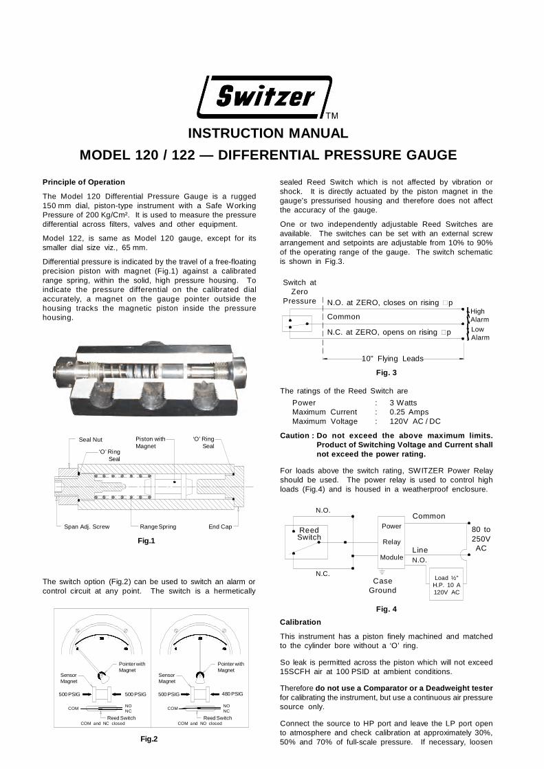
The Model 120 Differential Pressure Gauge is a rugged150 mm dial, piston-type instrument with a Safe WorkingPressure of 200 Kg/Cm². It is used to measure the pressuredifferential across filters, valves and other equipment.
Model 122, is same as Model 120 gauge, except for itssmaller dial size viz., 65 mm.
Differential pressure is indicated by the travel of a free-floatingprecision piston with magnet (Fig.1) against a calibratedrange spring, within the solid, high pressure housing. Toindicate the pressure differential on the calibrated dialaccurately, a magnet on the gauge pointer outside thehousing tracks the magnetic piston inside the pressurehousing.
The ratings of the Reed Switch are
Power : 3 WattsMaximum Current : 0.25 AmpsMaximum Voltage : 120V AC / DC
Caution : Do not exceed the above maximum limits.Product of Switching Voltage and Current shallnot exceed the power rating.
For loads above the switch rating, SWITZER Power Relayshould be used. The power relay is used to control highloads (Fig.4) and is housed in a weatherproof enclosure.
SensorMagnet
Pointer withMagnet
500 PSIG 500 PSIG
COMNONC
Reed Switch
SensorMagnet
Pointer withMagnet
500 PSIG 480 PSIG
COMNONC
Reed SwitchCOM and NC closed COM and NO closed
The switch option (Fig.2) can be used to switch an alarm orcontrol circuit at any point. The switch is a hermetically
Fig.2
sealed Reed Switch which is not affected by vibration orshock. It is directly actuated by the piston magnet in thegauge’s pressurised housing and therefore does not affectthe accuracy of the gauge.
One or two independently adjustable Reed Switches areavailable. The switches can be set with an external screwarrangement and setpoints are adjustable from 10% to 90%of the operating range of the gauge. The switch schematicis shown in Fig.3.
N.O. at ZERO, closes on rising p
Common
N.C. at ZERO, opens on rising p
10" Flying Leads
HighAlarm
UV|W|LowAlarm
Switch atZero
Pressure
Fig. 3
UV|W|
N.O.
ReedSwitch
N.C.
Power
Relay
Module
CaseGround
Load ½"H.P. 10 A120V AC
Common
LineN.O.
80 to250VAC
Fig. 4
Calibration
This instrument has a piston finely machined and matchedto the cylinder bore without a ‘O’ ring.
So leak is permitted across the piston which will not exceed15SCFH air at 100 PSID at ambient conditions.
Therefore do not use a Comparator or a Deadweight testerfor calibrating the instrument, but use a continuous air pressuresource only.
Connect the source to HP port and leave the LP port opento atmosphere and check calibration at approximately 30%,50% and 70% of full-scale pressure. If necessary, loosen
‘O’ RingSeal
Piston withMagnet
Seal Nut
End CapRange SpringSpan Adj. Screw
Fig.1
‘O’ RingSeal

the adjustment locknut, reset the adjustment screw andretighten locknut. Recheck calibration at 30%, 50% and70% of full-scale pressure.
Alarm Control Switch Adjustment
Switch setpoint is adjusted using the external adjustmentscrew (Fig.1). Turn screw clockwise to lower setpoint orcounter clockwise to raise setpoint. Turning screw 1/2 turnwill change the set point by approximately 1% of the full-scale.
INSTALLATION
Before Installation
Check gauge(s) against receiving paperwork; check forshipping damage and report immediately.
Model 120 / 122 Differential Pressure Gauges are fullyadjusted, calibrated and scaled to exact specifications beforeshipment, and are ready for immediate installation and use.The gauge may be line mounted to inlet and outlet pressureconnections, or flush mounted to a panel. An accessory isavailable to attach the gauge to a 2" support pipe for stanchionor wall mounting.
Tubing Connections
Connect the high pressure side of the system to the Highport and the low pressure side of the system of the Lowport of the gauge.
Note : A zero gauge reading when the system ispressurised, could indicate reversed High and Lowconnections.
Caution : When used in a high temperature system, thetubing to the gauge ports should be as long aspossible. To cool the fluid to less than200°F (90°C), a tube length of 6 feet is usuallyadequate to prevent high temperature fromdamaging the gauge.
Line Mounting
The gauge will be solidly supported if input nipples lessthan 3 inches in length are used. Use full-size 1/4" pipewhenever possible.
Panel Mounting (Fig.5)
1. Cut a 173.4 mm hole in panel.
2. Drill or punch 3 holes of 5.2 mm dia on 183.3 mm boltcircle diameter.
3. Remove 3 bezel screws.
4. Insert gauge into 173.4 mm hole from rear of panel.
5. Install and tighten 3 bezel screws through 3 holes drilledin Step 2.
Caution : The tubing connections to the gauge ports shouldbe of relatively flexible tubing, not rigid tubing.This will reduce the possibility of misalignmentbetween the mounted gauge and the tubing,during installation.
Disassembly
Before Attempting repairs
Contact SWITZER factory or nearest local office. Failure todo so will void any warranty
Bezel and Dial Chamber
1. Remove 3 bezel screws, bezel, lens /follower assembly,and lens gasket.
Remove two bridge-retaining screws, bridge and gaugepointer assembly.
Remove two dial-retaining screws and dial.
2. Separate dial chamber from pressure housing.
Pressure Housing
Caution : When tightening or loosening tubing connections,seal plug or adjustment locknut, secure pressurehousing using 1" wrench.
1. Turn off pressure to any tubing connected to gauge andremove tubing connections from gauge ports.
2. Loosen adjustment locknut and remove adjustment screwwith its ‘O’ ring.
3. Remove seal plug with its ‘O’ ring.
4. Using a pencil or wooden dowel, push the piston andspring out o the housing.
Reassembly
Before reassembling gauge, thoroughly clean the housing,piston and all metal parts with detergent solution or mildsolvent.
Caution : Do not use strong solvents (acetone, ether,toluene, etc.,) to avoid damage to dial or bezel.
Note : Use new seal ‘O’ rings when reassembling housing.
1. Lubricate ‘O’ rings and all sealing surfaces with siliconegrease and apply a thick film to the piston and housingcylinder.
2. Reassemble gauge by reversing disassembly procedure.
M16 × 1.5CableEntry
+0.5–0.0155.0 Ø
3 Holes
L.PH.P
120°
IM–1
20 R
ev.1
A(0
915)
Fig.5
5.5Ø at165.0 PCD
Switzer Process Instruments Pvt. Ltd.Switzer Process Instruments Pvt. Ltd.Switzer Process Instruments Pvt. Ltd.Switzer Process Instruments Pvt. Ltd.
REGD. OFFICE : 128, Sidco North Phase, Ambattur Estates, Chennai 600 098.
PH: 044– 26252017 / 26252018 FAX: 044–26248849
E-MAIL: [email protected]; [email protected]: www.switzerprocess.co.in