instruction manual m mooddeelliinngg tthhee clerget 9b clerget... · 2019-05-24 · although a...
TRANSCRIPT
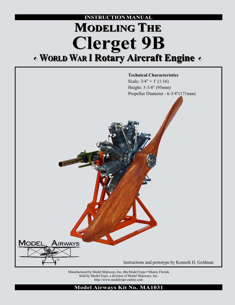
INSTRUCTION MANUAL
MMMOOODDDEEELLLIIINNNGGG TTTHHHEEE
CClleerrggeett 99BB ♦♦ WWWOOORRRLLLDDD WWWAAARRR III RRRoootttaaarrryyy AAAiiirrrcccrrraaafffttt EEEnnngggiiinnneee ♦♦
Technical Characteristics Scale: 3/4" = 1' (1:16) Height: 3-3/4" (95mm) Propeller Diameter : 6-3/4"(171mm)
Instructions and prototype by Kenneth H. Goldman
Manufactured by Model Shipways, Inc. dba Model Expo • Miami, Florida Sold by Model Expo, a division of Model Shipways, Inc.
http://www.modelexpo-online.com
Model Airways Kit No. MA1031

CLERGET 9B ROTARY ENGINE (1:16 SCALE)
The model was designed for Model Airways by Microfusioni - modellisimo of Milan, Italy, owned by Luigi Volonté and son Bruno. Instructions, engine stand and completed model are by Kenneth H. Goldman.
HISTORY
Developed by Clerget and manufactured in France, the Clerget 9B was an improvement over the company's seven cylinder, 80 hp rotary engine. In versions of 110 to 140 hp, these models saw widespread use throughout the first world war in the F.1 Camel, Triplane and Baby by Sopwith, and in the Nieuport 12. The model 9B was rated at 130 hp in normal use but could be pushed to 135 in an emergency at 1,250 rpm. Maximum weight was 380 pounds.
Although a counter-intuitive design by today’s standards, fixing the propeller to a spinning engine on a stationary crankshaft simplified cooling, had an excellent weight to horsepower ratio and allowed greater flexibility in locating the aircraft’s center of gravity – affecting maneuverability -- over the in-line engines of the time. One drawback, however, was the pronounced gyroscopic effect that pulled the aircraft to the right. To fly in a straight line, pilots had to compensate for this by applying constant left rudder.
The Clerget rotaries provided improved speed control over the Gnome and Le Rhone rotaries by replacing the standard “blip” switch that temporarily grounded the magneto (killing the ignition) with a selector switch that restricted the engine to run on 9, 7, 5 or even 3 cylinders. Like the earlier rotaries, the Clerget spewed unburned castor-oil from the exhaust, adding to the pilot’s discomfort. Pilots were issued a small bottle of blackberry brandy to counteract the smoke’s laxative effect.
STEP 1 -- ENGINE STAND
Using wood glue, assemble six of the seven laser-cut parts per the photographs, taking care that the base issquare. Angle brace CLE908c is centered between the two small holes below the engine cradle in partCLE908a. Semicircular piece CLE908b is attached later. The actual stand would be steel, so primer coat theassembled stand and paint your desired color. Note the orientation of parts CLE916b.
STEP 2 -- ENGINE FRONT SUBASSEMBLY
Clean up and dry fit all parts before gluing with either cyanoacrylate glue or 5-minute epoxy resin. The castparts can be polished with a brass brush and left unpainted or painted and weathered to suit. If leaving theparts polished, it is recommended to seal the completed engine with a light coat of spray varnish.
Page 1

Page 2

Referring to Fig. 02, attach the front and back crankcase covers (CLE-03) to the crankcase (CLE-02). Note the tiny notches in the castings to help you align the parts. Glue one side in place, then make sure the bolts heads line up on both covers before gluing the second cover in place. Slip this subassembly onto the brass tube (KS-129), which for now, serves as an engine alignment jig. Do not glue the cast parts to the tube.
Referring to Fig. 04 and Photo 1, slip the nine cylinders (CLE-11) over the pistons on the crankcase so that the paired sparkplug holes all face the same way, perpendicular to the central axis of the crankcase. Now hold the subassembly facing you so that the sparkplug holes are to the left on the cylinder at the top. This is the front of the engine. Slip the camshaft box (CLE-06) onto the brass sleeve and align it so the paired depressions for the tappet seats (GS2-3) are centered in front of each cylinder. Looking at the top cylinder, the left hand of each pair should be closer to you (Fig. 03 and Photo 3). Glue CLE-06 against the crankcase. For the best fit of the tappet seats (GS2-3) later on, use a 3/32” twist drill to clean the 18 depressions in CLE-06. Finish up with a quick twist from a 7/64” drill to bevel the edges. Be careful not to drill too deep.
Refer to Photo 1 to align the cylinder heads (CLE-12) on the cylinders before you glue them in place. NOTE that the two flats on the top do not match: the larger one, with straighter sides, also has the larger hole; it is for the intake rocker arm, which goes to the side opposite the sparkplug holes. The flats should line up with the central axis of the engine, which will set the two holes at an angle to that axis. Next, glue the intake rocker arms (CLE-15i) to the cylinder heads so that the flanged pipe on each goes to the rear of the engine (Figs. 03 and 04).
Slip the induction box (CLE-07) onto the brass tube at the rear of the engine. Referring to Engine Photograph 2, holding an induction pipe (CLE-16) in place, flanged end against a flat on the CLE-07, position the flat on the induction box so that the flat side of the other end of the pipe meets the center of the flanged pipe on the intake rocker arm. Properly aligned, it will be at a slight angle. Glue CLE-07 to the crankcase. Dry fit each induction pipe and adjust the flat as necessary to fit against the pipe on each CLE-15i and glue them into place. File off any part of each induction pipe that extends above the edge of the flanged pipe on parts CLE-15i (Photo 2 and Figs. 01 and 04).
Glue the igniter ring (CLE-08) to the induction box so that the holes line up between each pair of cylinders and the small gear faces away from the engine.
Glue the exhaust rocker arms (CLE-15e) in place on the cylinder heads. Cut the 18 valve lifters (CLE-13) from the provided lengths of 1/32” brass rod. It is suggested that you cut them to 15/16” and then file them down to achieve the best fit. Slide a tappet seat (GS2-3) onto each brass rod and glue into place, referring to Photo 3 and Figs. 01 and 03.
Remove the brass tube and cut a piece 1 1/2" long. Slide this crankshaft tube back into the engine and glue in place so that the rear end is flush with the outside of CLE08. Complete the engine by attaching the ignition wires (MS1218) from the igniter ring to the spark plugs, referring to Photo 4. Cut nine 8” lengths of black thread. Fold these in half, making two 4" pairs of threads, and feed the looped end of each pair through one of the nine holes in the igniter ring. Cut the loop and tie one end each sparkplug terminal. Alligator clips or other small clamps can be used on the thread ends that emerge from the hole to act as weights to keep the threads taut as you fix them and the knots with a drop of glue. Trim off the excess thread and repeat the process for the other eight cylinders.
STEP 3 -- ENGINE REAR SUBASSEMBLY
Referring to Fig. 06, glue together parts CAF42a & b, then mount the two magnetos. Glue the manual starter (CAF44) to the gear housing (CAF38GB). Dry fit the gear housing to the engine stand. Holding them together, dry fit the magnetos assembly to the gear housing to ensure the magnetos platform will be level to the engine stand when the platform is glued to the gear housing. Make any needed adjustments, then glue the magnetos and platform to the gear housing. Glue the oil pump (CAF39) atop the air pump (CAF40) taking care that the pipe on the air pump points to the engine left. Glue the two pumps to the gear housing.
Page 3

Cut two 1" lengths of the brass tube (KS-129) and one 1 1/2" length. Grind or file one end of each 1" tube to a106° angle to make the air scoops. Referring to Fig. 07, glue these onto the carburetor (CAF45), angled endsout and facing forward. Glue the end cap (CAF73) to the 1 1/2" tube. Slide the carburetor assembly onto thebrass tube and glue it against the end cap. Be careful to square up the parts and make sure the air scoops faceaway from the end cap. Glue the remaining brass eyelet (GS2-3) atop the carburetor.
The rear engine support(CAF43) is optional in thisarrangement, though it does helpto balance the weight of thecompleted model, and istherefore recommended. Shouldyou wish to use it, paint it zincchromate green and slide it ontothe brass tube. Do not glue yet.
Glue the gear housing assemblyto the engine stand. The standcradle should snug up againstthe flange on the gear housing.
CAF38GB
Glue the semicircular part CLE908b over the gear housing. Either drill holes for the two false bolts (CAF46) or cut off the longer ends and simply glue in place.
Page 4

Insert the brass tube into the gear housing so itprotrudes 1/16" on the inside. Glue into place sothe air tubes are horizontal. If you are includingthe rear engine support, center it between thecarburetor and the rearmost extension of thegear housing assembly, then glue it in place soits arms are horizontal.
STEP 4 -- PROPELLER AND COMPLETION
Referring to Fig.05 on page 2, laminate the propeller layers (CLE17). Take care to stack the layers in the correct order. When viewed from the front in a vertical position, the stack goes from longest to shortest with the shortest layer closest to you. Curved edges would then be upper left and lower right. A 1/4" diameter bolt and nut make a handy center clamp that helps align the layers while the glue dries.
Remove the bolt and whittle and sand the propeller to its refined shape. The front of the finished propeller curves toward the back when viewed from the side. Begin with the overall lengthwise curve, then proceed to the cross-sectional shaping. This will result in a curved leading edge and a straight trailing edge after the final shaping. Shape the front first, then the back to follow the front. Note that the front surface is slightly convex and the back is slightly concave. When you are satisfied with the result, apply a gold-mahogany stain. If using a water-base stain you might have to lightly re-sand the propeller with #400 paper to remove any raised wood grain, then apply a couple of coats of varnish.
Attach the front (CLE04) and rear( CLE05) flanges to the propeller. Make sure the front and rear bolt heads/nuts line up before gluing, then glue the propeller to the crankshaft tube. Finally, slide the brass tube (KS-165) into the brass tube in the engine rear subassembly, then slide the engine subassembly onto the other end. Gluing these together is optional.
CAF38GB
CAF46
CAF46
Page 5