instruction manual - · pdf fileavailable in an 8 amp peak dc motor version, ... 4 motor...
TRANSCRIPT
Cruise Commander M TM
Instruction Manual
Revised: October, 2008

2
Cruise Commander
TMCC Compatible DC Cruise Command Upgrade Board
Overview The patented Cruise Commander with SMS* Technology tm is a breakthrough in cruise control technology for 3-rail. The Cruise Commander product line uses motor commutation and back-EMF to monitor the speed of the motor(s) attached instead of an external tachometer sensor. This method of motor control is easier to install than attaching an optical tachometer and timing tapes, and does not require flywheels on the motor. With the Cruise Commander product installed, the performance of the locomotive will be greatly enhanced.
The Cruise Commander product line has a lash-up feature, referred to as “nudge mode”. The mode allows a person to match the locomotives in a lash-up. Once the speeds are matched, they dynamically adjust with throttle position. The “nudge” settings are saved for future operating sessions, however they may be easily reset.
The Cruise Commander is capable of operating in 32- speed step mode for speed profile compatibility with most existing engines. The default setting for the Cruise Commander is 100-speed steps. The Cruise Commander uses the sound system to indicate configuration changes by blowing the whistle/horn for acknowledgement.
SMS* - Speed Management System
Enhanced Features Simple “Tach-Less” operation Same footprint and wiring as Lionel modular system Operates in command and conventional modes Single or Dual DC motor capability (8 amps peak) CAB-1tm selectable 32 or 100(default) speed steps Ditch Lamp and Marker Lamp outputs provided Uses existing mounting brackets in locomotive
Full Functions Available in an 8 Amp peak DC motor version, additionally supporting oscillating Ditch Lamps and Marker Lamp outputs.
Small Footprint 1.98” L x 1.28” W x 1.00” H footprint
Included with Board Hook-up wires, heat shrink, wire ties
3
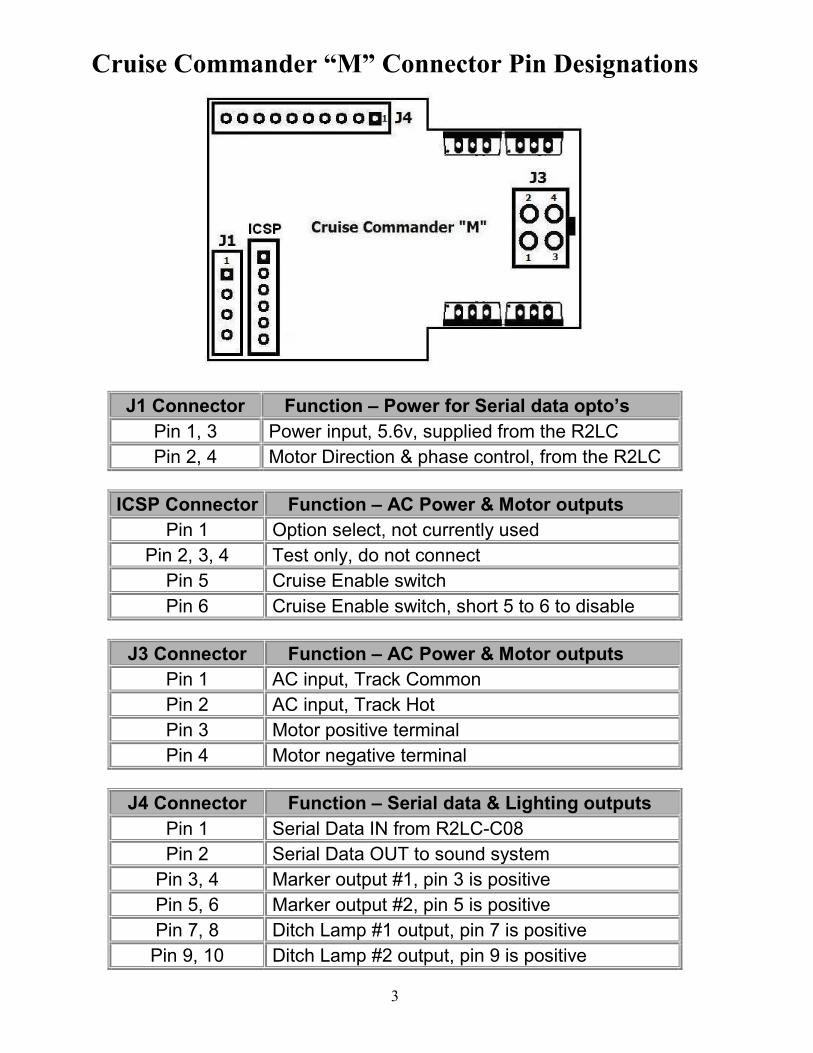
Cruise Commander “M” Connector Pin Designations
J1 Connector Function – Power for Serial data opto’s
Pin 1, 3 Power input, 5.6v, supplied from the R2LC
Pin 2, 4 Motor Direction & phase control, from the R2LC
ICSP Connector Function – AC Power & Motor outputs
Pin 1 Option select, not currently used
Pin 2, 3, 4 Test only, do not connect
Pin 5 Cruise Enable switch
Pin 6 Cruise Enable switch, short 5 to 6 to disable
J3 Connector Function – AC Power & Motor outputs
Pin 1 AC input, Track Common
Pin 2 AC input, Track Hot
Pin 3 Motor positive terminal
Pin 4 Motor negative terminal
J4 Connector Function – Serial data & Lighting outputs
Pin 1 Serial Data IN from R2LC-C08
Pin 2 Serial Data OUT to sound system
Pin 3, 4 Marker output #1, pin 3 is positive
Pin 5, 6 Marker output #2, pin 5 is positive
Pin 7, 8 Ditch Lamp #1 output, pin 7 is positive
Pin 9, 10 Ditch Lamp #2 output, pin 9 is positive
4
Installation
Note: If you are installing a Cruise Commander M into a
steam engine with a wireless tether, you will need an extra cable.
Call Electric RR Company, 408-454-4127
The Cruise Commander “M” system is designed for operation in locomotives with modular factory TMCC with little or no modification to the loco wiring. The Cruise “M” also will be a great choice for locos that have K-Line cruise, or Odyssey™ cruise systems.
Examples will guide you through the install, however many common elements exist in the install process independent of locomotive selected for upgrade. The Cruise “M” requires the following minimal connections. First, the power and motor connector needs identified. This is a 4 or 6 pin Molex connector with wires that typically are Red (3rd rail), Black (track common), and 2 wires that connect to the motor(s). If this is a 6-pin connector, a 4-pin Molex adapter cable to make the connection is available. (The 4-pin cable is included in the Cruise “M” Odyssey™ version) Next, the R2LC direction control signals need attached to J1. The Lionel locos will have this same connector attached to the board you remove, and this connection will directly connect to the Cruise “M”. A 4-pin cable is included in the Cruise “M” kit for locos that do not have this wire harness (K-Line). Finally, the serial data must be connected to the Cruise “M” for speed step and setting the configuration information. This connection does not exist on Lionel locos, but does exist in K-Line cruise locos. Identification of this wire is paramount to a successful installation, and typically this connection is available on the motherboard where the R2LC is located. A few examples are shown, and if necessary, this signal can be obtained by soldering a wire on the R2LC. Marker and ditch lamp outputs are provided on the Cruise “M” for locos with these features. The outputs are capable of driving LED’s only. Ditch lamps flash when the horn is activated (command mode only).
5
Installation Examples
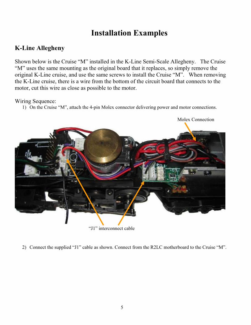
K-Line Allegheny Shown below is the Cruise “M” installed in the K-Line Semi-Scale Allegheny. The Cruise “M” uses the same mounting as the original board that it replaces, so simply remove the original K-Line cruise, and use the same screws to install the Cruise “M”. When removing the K-Line cruise, there is a wire from the bottom of the circuit board that connects to the motor, cut this wire as close as possible to the motor. Wiring Sequence:
1) On the Cruise “M”, attach the 4-pin Molex connector delivering power and motor connections.
Molex Connection
“J1” interconnect cable
2) Connect the supplied “J1” cable as shown. Connect from the R2LC motherboard to the Cruise “M”.
6
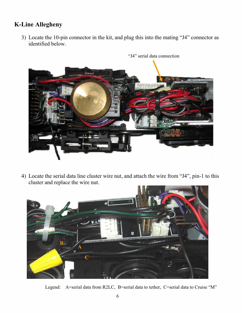
K-Line Allegheny
3) Locate the 10-pin connector in the kit, and plug this into the mating “J4” connector as identified below.
“J4” serial data connection
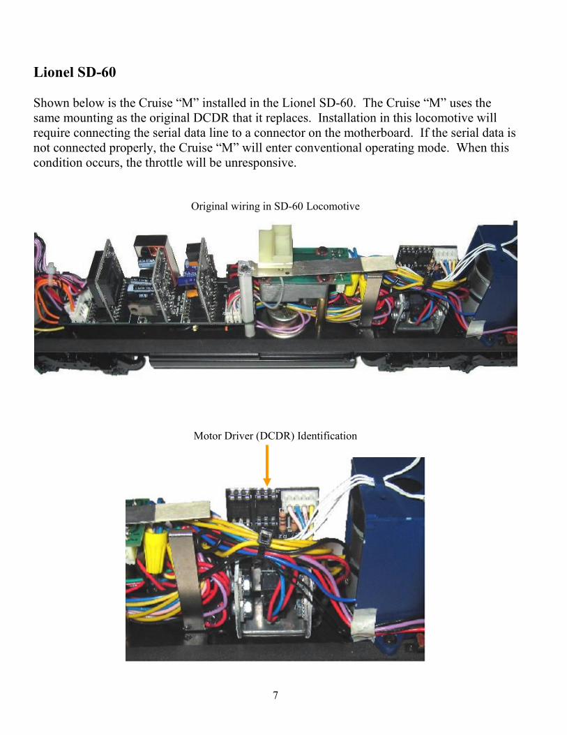
4) Locate the serial data line cluster wire nut, and attach the wire from “J4”, pin-1 to this
cluster and replace the wire nut.
Legend: A=serial data from R2LC, B=serial data to tether, C=serial data to Cruise “M”
A B
C
7
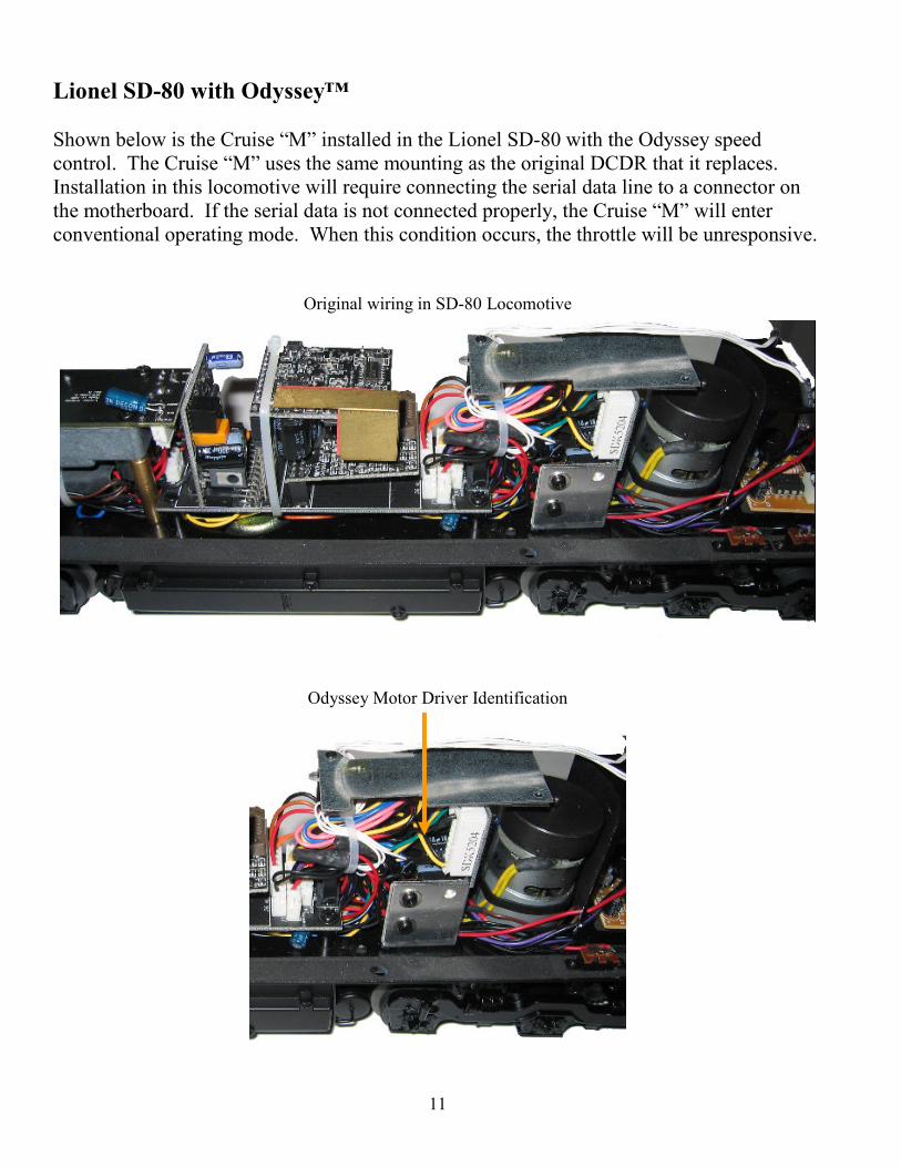
Lionel SD-60 Shown below is the Cruise “M” installed in the Lionel SD-60. The Cruise “M” uses the same mounting as the original DCDR that it replaces. Installation in this locomotive will require connecting the serial data line to a connector on the motherboard. If the serial data is not connected properly, the Cruise “M” will enter conventional operating mode. When this condition occurs, the throttle will be unresponsive.
Original wiring in SD-60 Locomotive
Motor Driver (DCDR) Identification

8
Lionel SD-60 In this example, the DCDR will be removed and replaced with the Cruise “M”. Mounting of the DCDR in this loco was done with a single screw at the bottom center of the heat sink. The screw was easily removed by slipping a screwdriver through the truck by the wheel. Once the DCDR is free, unplug the 2 connections and remove the DCDR. On this loco the cab lamps were soldered to the DCDR, next cut or unsolder these from the PCB.
Cab Lamp Connections
Transplant the heat sink from the DCDR to the Cruise “M”, the screws from the original DCDR may be used. Be sure to retain the original mounting orientation.
Transplanted Heat Sink

9
Lionel SD-60 Install the Cruise “M” the same way as the original DCDR motor driver, with the single screw in the heat sink. When mounted, next attach the original cables to the Cruise “M” as shown below.
4-Pin Motor Phase Connection Power and Motor Brush Connection
Plug in the 10-pin cable harness, shown below. In this minimalist example, the only wire is the serial data on pin-1. Dress the wires and route the signal along the existing wiring harness, keeping all wires away from the smoke unit bowl, which can get fairly hot. 10-pin connector with serial data wire

10
Lionel SD-60 The serial line from the Cruise “M” will need to be attached as shown below. It is best to route the wire above the R2LC to prevent the wire from being pinched between the shell and the motherboard. Notice the location where the wire is attached. This is an easy location to access for soldering the serial data wire to, and will facilitate removal of the R2LC if needed.
Serial data wire connection
Advanced wiring considerations:
• The serial data is repeated on pin-2 of the 10-pin connector on the Cruise “M”. In this repeated data stream, any configuration changes on the Cruise “M” will inject a “horn” command. This can be used for confirmation of configuration changes.
• The SD-60 in this example has incandescent ditch lamps, which remain on when moving forward. The lamps could be replaced with white LED’s, and when attached to the Cruise “M” they will oscillate when the horn is blown (command mode only).
Please contact [email protected] for assistance if these features are desired.
11
Lionel SD-80 with Odyssey™ Shown below is the Cruise “M” installed in the Lionel SD-80 with the Odyssey speed control. The Cruise “M” uses the same mounting as the original DCDR that it replaces. Installation in this locomotive will require connecting the serial data line to a connector on the motherboard. If the serial data is not connected properly, the Cruise “M” will enter conventional operating mode. When this condition occurs, the throttle will be unresponsive.
Original wiring in SD-80 Locomotive
Odyssey Motor Driver Identification
12
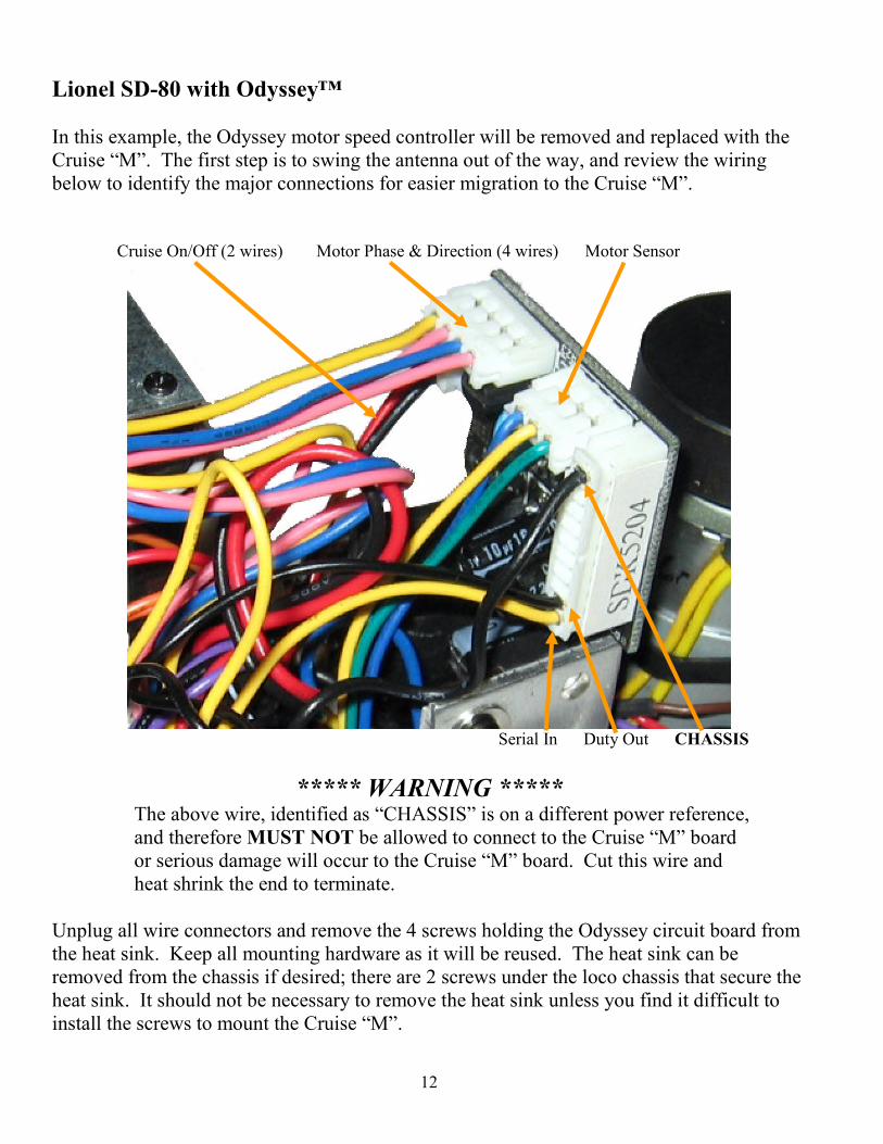
Lionel SD-80 with Odyssey™ In this example, the Odyssey motor speed controller will be removed and replaced with the Cruise “M”. The first step is to swing the antenna out of the way, and review the wiring below to identify the major connections for easier migration to the Cruise “M”. Cruise On/Off (2 wires) Motor Phase & Direction (4 wires) Motor Sensor
Serial In Duty Out CHASSIS
***** WARNING *****
The above wire, identified as “CHASSIS” is on a different power reference, and therefore MUST NOT be allowed to connect to the Cruise “M” board or serious damage will occur to the Cruise “M” board. Cut this wire and heat shrink the end to terminate.
Unplug all wire connectors and remove the 4 screws holding the Odyssey circuit board from the heat sink. Keep all mounting hardware as it will be reused. The heat sink can be removed from the chassis if desired; there are 2 screws under the loco chassis that secure the heat sink. It should not be necessary to remove the heat sink unless you find it difficult to install the screws to mount the Cruise “M”.

13
Lionel SD-80 with Odyssey™ There will be a 6-pin Molex connector that supplies power and motor connections. Identify this connector shown below, and cut off the 4 wires going to the connector. These wires are usually Red (3rd rail), Black (common), Blue and Yellow (motor brushes). These wires will need to be spliced into the 4-pin Molex cable provided that attaches to the Cruise “M”.
Cut off this Molex connector
Plug in the supplied 4-pin connector to the Cruise “M”, and reattach all 4 FET drivers to the heat sink. Then splice the Red and Black wires, connecting the Cruise “M” and the wires that were cut from the 6-pin Molex connector as shown.
Splice the Red and Black wires

14
Lionel SD-80 with Odyssey™ Reattach all connectors to the Cruise “M”, except the “Motor Sensor” which is not used. A detail is shown below of the “Cruise On/Off” connection, which is attached to the last 2 pins of the “ICSP” connector. This is a bit tricky, so be sure to get this right. Damage will occur if done incorrectly. Unconnected Motor Sensor harness
All connections completed, except for the motor brushes (Blue and Yellow wires)
Shown below is a close-up detail of the “Cruise On/Off” switch connection on the ICSP connector. Note the connection on the far left 2 pins, and verify you can see 4 unconnected pins to the right of the plug, indicating that indeed the left 2 pins are connected to the plug.
Note the 4 pins visible that are unconnected
15
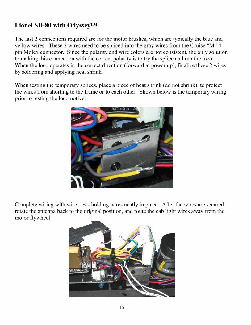
Lionel SD-80 with Odyssey™ The last 2 connections required are for the motor brushes, which are typically the blue and yellow wires. These 2 wires need to be spliced into the gray wires from the Cruise “M” 4-pin Molex connector. Since the polarity and wire colors are not consistent, the only solution to making this connection with the correct polarity is to try the splice and run the loco. When the loco operates in the correct direction (forward at power up), finalize these 2 wires by soldering and applying heat shrink. When testing the temporary splices, place a piece of heat shrink (do not shrink), to protect the wires from shorting to the frame or to each other. Shown below is the temporary wiring prior to testing the locomotive.
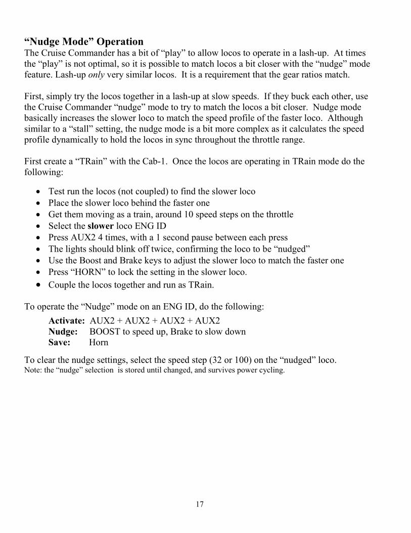
Complete wiring with wire ties - holding wires neatly in place. After the wires are secured, rotate the antenna back to the original position, and route the cab light wires away from the motor flywheel.

16
Option Setting Overview
The Cruise Commander “M” product line is unique in that the R2LC firmware revisions may vary, as the R2LC is not included in the kit. As a result to be compatible with the R2LC-C08 to R2LC-C11 and R2LC-C13, the option selection sequence is slightly different as indicated below. As a bonus, when using R2LC-C11 & R2LC-C13; the momentum commands are re-purposed to adjust the speed step selection: L = 32-speed steps, M = 100- speed steps, and H = 100-speed steps. Note: The speed step selection changes only when the throttle is set to zero.
Speed Step Selection The default speed step selection is 100 as shipped. The 100-speed steps are linear. The 100-speed steps start at a lower threshold, thus the motor is operating at a lower initial voltage with fine adjustment as the throttle is advanced. The momentum and stall features are not applicable and do not operate. To switch Speed Steps do the following:
Activate 32-Speed Steps: AUX1 + DIR + AUX1 + DIR + BRAKE Activate 100-Speed Steps: AUX1 + DIR + AUX1 + DIR + BOOST
Note: The speed step selection is stored until changed, and survives power cycling.
Motor Type Selection The Cruise Commander requires you to set the motor type. Motors are classified as small or large. Selecting the wrong motor size won’t hurt anything, but operation is best when matched. The default motor type is “large motor” for the Cruise Commander. To switch Motor Type do the following:
Activate Small Motor: AUX1 + DIR + AUX1 + 1 Activate Large Motor: AUX1 + DIR + AUX1 + 2
Note: The motor type selection is stored until changed, and survives power cycling.
Cruise Off/On Selection The Cruise feature may be turned off or on. This setting is stored and affects command and conventional mode operation. To turn the Cruise OFF or ON, do the following:
Cruise Off: AUX1 + DIR + AUX1 + BRAKE + 7 + BRAKE Cruise On: AUX1 + DIR + AUX1 + BRAKE + 9 + BRAKE
Note: The cruise off/on selection is stored until changed, and survives power cycling.
17
“Nudge Mode” Operation The Cruise Commander has a bit of “play” to allow locos to operate in a lash-up. At times the “play” is not optimal, so it is possible to match locos a bit closer with the “nudge” mode feature. Lash-up only very similar locos. It is a requirement that the gear ratios match. First, simply try the locos together in a lash-up at slow speeds. If they buck each other, use the Cruise Commander “nudge” mode to try to match the locos a bit closer. Nudge mode basically increases the slower loco to match the speed profile of the faster loco. Although similar to a “stall” setting, the nudge mode is a bit more complex as it calculates the speed profile dynamically to hold the locos in sync throughout the throttle range. First create a “TRain” with the Cab-1. Once the locos are operating in TRain mode do the following:
• Test run the locos (not coupled) to find the slower loco
• Place the slower loco behind the faster one
• Get them moving as a train, around 10 speed steps on the throttle
• Select the slower loco ENG ID
• Press AUX2 4 times, with a 1 second pause between each press
• The lights should blink off twice, confirming the loco to be “nudged”
• Use the Boost and Brake keys to adjust the slower loco to match the faster one
• Press “HORN” to lock the setting in the slower loco.
• Couple the locos together and run as TRain. To operate the “Nudge” mode on an ENG ID, do the following:
Activate: AUX2 + AUX2 + AUX2 + AUX2 Nudge: BOOST to speed up, Brake to slow down Save: Horn
To clear the nudge settings, select the speed step (32 or 100) on the “nudged” loco. Note: the “nudge” selection is stored until changed, and survives power cycling.
18
Setting the R2LC ID and Feature Code
Setting the engine ID Number:
The R2LC Receiver comes with its engine ID set to ENG ‘1’. To change the engine ID, follow this procedure.
1. Make sure the Command Base is connected to the track 2. Set the engine PROGRAM / RUN switch to “PROGRAM” 3. Place the engine on the track and apply power 4. On the CAB-1, press [ENG] then the number (1 - 99) for the engine desired 5. Press [SET] (the engine ID is saved until you need to change it again) 6. Press [AUX1] [n], where n = the engine feature code (this must be done!) 7. Remove power from the track and place the switch back into the ‘RUN’ Position
Feature Code information:
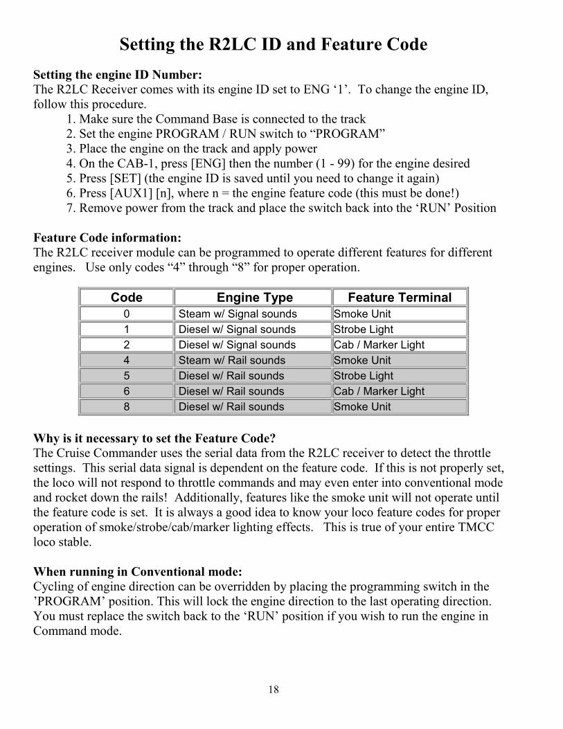
The R2LC receiver module can be programmed to operate different features for different engines. Use only codes “4” through “8” for proper operation.
Code Engine Type Feature Terminal
0 Steam w/ Signal sounds Smoke Unit
1 Diesel w/ Signal sounds Strobe Light
2 Diesel w/ Signal sounds Cab / Marker Light
4 Steam w/ Rail sounds Smoke Unit
5 Diesel w/ Rail sounds Strobe Light
6 Diesel w/ Rail sounds Cab / Marker Light
8 Diesel w/ Rail sounds Smoke Unit
Why is it necessary to set the Feature Code?
The Cruise Commander uses the serial data from the R2LC receiver to detect the throttle settings. This serial data signal is dependent on the feature code. If this is not properly set, the loco will not respond to throttle commands and may even enter into conventional mode and rocket down the rails! Additionally, features like the smoke unit will not operate until the feature code is set. It is always a good idea to know your loco feature codes for proper operation of smoke/strobe/cab/marker lighting effects. This is true of your entire TMCC loco stable. When running in Conventional mode:
Cycling of engine direction can be overridden by placing the programming switch in the ’PROGRAM’ position. This will lock the engine direction to the last operating direction. You must replace the switch back to the ‘RUN’ position if you wish to run the engine in Command mode.
19
Limited Warranty
The Electric Railroad Company warrants to the original consumer purchaser that this product will be free of defects in materials and workmanship for a period of 90 days from the date of original purchase. This warranty does not cover service, repair, or replacement to correct any damage caused by improper installation, improper connection, external electrical fault, accident, disaster, misuse, abuse, or modifications to the product. All other express or implied warranties, including the implied warranty of merchantability and fitness for a particular purpose, are hereby disclaimed. If this product is not in good working order as warranted, the sole and exclusive remedy shall be repair or replacement. In no event shall The Electric Railroad Company, or any dealer, distributor, or authorized installation and/or repair service provider be liable for any damages in excess of the purchase price of the product. This limitation applies to damages of any kind, including but not limited to, direct or indirect damages, lost profits, lost savings or other special, incidental, exemplary or consequential damages whether for breach of contract, tort or otherwise, or whether arising out of the use of or inability to use the product, even if The Electric Railroad Company, or any dealer, distributor, or service provider has been advised of the possibility of such damages or any claim by any other party. Some states do not allow the exclusion or limitation of incidental or consequential damages so the above limitation or exclusion may not apply to you. During this warranty period, the product will either be repaired or replaced (at our option) without charge to the purchaser, when returned either to the dealer with proof of the date of purchase or directly to The Electric Railroad Company when returned prepaid and insured with proof of date of purchase. Some states do not allow limitations on how long an implied warranty lasts, so such limitations may not apply to you. This warranty gives you specific legal rights, and you may also have other rights, which vary from state to state.
Repairs
Each and every product is thoroughly tested before it is shipped. The likelihood that it is not working when it reaches you is very small. However, if after troubleshooting it yourself you cannot get it to work properly, you should contact us to help determine the problem. Should your product ever need repair, you should return it postpaid directly to The Electric Railroad Company. If the product is within the warranty period, it will be repaired or replaced and returned to you free of charge. Units out of warranty will be repaired or replaced for a service charge of $50.00 at our option. Please email to [email protected] for return authorization before returning any product.
Disclaimer
Improper installation or configuration of the Cruise Commander Board can cause
overheating and fires! Since it is not possible to understand every installation, it is the
consumer’s responsibility to verify proper operation of the upgrade to prevent malfunction.
If you are unsure of install,, please contact us first before taking any risks!
All manual contents are Copyright ©2006, The Electric Railroad Company, 2326 Walsh Avenue, Santa Clara, CA. TMCC, CAB-1, R2LC, SignalSounds, and RailSounds are registered trademarks of Lionel, LLC.