instruction manual - ht2000 v 1 - mcs test equipment · · 2017-11-06safety precautions ... model...
TRANSCRIPT


i
ii
Dear Customer: Congratulations! Compliance West USA is proud to present you with your Dielectric Withstand Tester. Your instrument features a groundbreaking logic-controlled circuit design and ergonomic front panel, and represents the latest in high voltage production line testing. To fully appreciate all the features of your new meter, we suggest that you take a few moments to review this manual. If the need arises, please don't hesitate to call on us. Thank you for your trust and confidence.
Rev. 6.1, February 2013

iii
iv
Table of Contents
An Introduction to Dielectric Withstand Testing with the HT-5000P ......................................................................... 2
Safety Precautions ........................................................................................................................................ 2
Test Personnel .............................................................................................................................. 2
Testing Area ................................................................................................................................. 2
Safety Techniques ........................................................................................................................................ 3
Using the HT-5000P Dielectric Withstand Tester........................................................................................ 3
Leakage Test ................................................................................................................................ 3
Sporadic Leakage Current Failures .............................................................................. 4
Chronic Leakage Current Failures ................................................................................ 4
High Voltage Dielectric Withstand Test ...................................................................................... 4
High Voltage Dielectric Withstand Test Failures ......................................................... 5
High Voltage Discharge ............................................................................................... 5
Introduction and Specifications ................................................................................................................................... 6
Specifications ............................................................................................................................................... 7
Table 1. HT-5000P Specifications .............................................................................................. 7
Operation ..................................................................................................................................................................... 8
Setting up your Tester .................................................................................................................................. 8
AC Line Voltage Requirements ................................................................................................................... 8
Fuse Replacement ........................................................................................................................................ 8
Front and Rear Panel Features ..................................................................................................................... 9
Figure 1. Controls, Indicators, Connectors - Model HT-5000P Front Panel............................... 9
Table 2. Controls, Indicators, Connectors - Model HT-5000P Front Panel ................................ 10
Figure 2. Controls, Indicators, Connectors - Model HT-5000P Rear Panel ................................. 11
Table 3. Controls, Indicators, Connectors - Model HT-5000P Rear Panel ................................. 12
Factory Settings ............................................................................................................................ 13
Display of Leakage Limit and Duration settings .......................................................................... 13
Adjustment of the Leakage Current Level .................................................................................... 13
Adjustment of the High Voltage Ramp Time ............................................................................... 13
Adjustment of the High Voltage Level ......................................................................................... 14
Adjustment of the High Voltage Test Time.................................................................................. 14
Setting the Rear Panel Switches ................................................................................................... 14
Table 4: Rear Panel Switch Truth Table ....................................................................... 15
Table 5: Rear Panel Switch Condition Table ............................................................... 15
Operating Techniques .................................................................................................................................. 15
Operation Test .............................................................................................................................. 16
Testing .......................................................................................................................................... 17
Example Test Procedure: .............................................................................................. 17
Figure 3: Connection Example ..................................................................................... 17
Test results ................................................................................................................................... 18
Hipot Pass .................................................................................................................... 18
Red LED/Buzzer .......................................................................................................... 18
Technical Assistance .................................................................................................................................................... 19
Maintenance and Calibration ....................................................................................................................................... 20
Introduction ................................................................................................................................................. 20
Service Information...................................................................................................................................... 20
General Maintenance ................................................................................................................................... 20
Interior Access ............................................................................................................................. 20
Calibration Access ........................................................................................................ 21
Cleaning ....................................................................................................................................... 21
Calibration Procedure .................................................................................................................................. 21
Calibration and Software Version Information ............................................................................ 22
Voltage Calibration Adjustment ................................................................................................... 22
Current Calibration Adjustment ................................................................................................... 23

1

2
Section 1
An Introduction to Dielectric Withstand Testing with the HT-5000P
The dielectric withstand test is a production line test which is recognized by safety agencies
worldwide as a valid criterion of safe assembly of end-use equipment. The test ensures that the primary
circuit power was properly wired and connected for safe operation. It also applies a high-voltage
potential between power and ground conductors to make sure that no unintentional leakage or arcing
paths exist between power and ground. The test consists of a leakage current check and a high voltage
check. It is non-destructive to the equipment under test, and can be accomplished in a short time.
Safety Precautions
The dielectric withstand test generates voltages of up to 5000 volts AC or 6000 volts DC at
potentially lethal current levels. Currents of as little as 5 mA at 120 volts can cause death, and the HT-
5000P is capable of generating 10 mA AC at up to 5000 volts, and 5 mA DC at up to 6000 volts. The
HT-5000P has been designed to minimize exposure to high voltages. However, the potential for serious
injury or death exists and personnel should be aware when they conduct this test.
Test Personnel
Personnel require special training to conduct the dielectric withstand test. They should
understand electrical fundamentals clearly, and be aware that high voltage is adept and creative at
completing a path to ground. Instructions should include a warning against any metal jewelry. Operators
should not allow others in the testing area, especially when tests are being conducted. Organization is to
be stressed. The operator should keep the area free of unused leads and equipment.
Testing Area
The area used for conducting the dielectric withstand test should be as remote as possible from
normal production line activities. Only personnel actually conducting the test should be allowed in the
area, and it should be taped or roped off to preclude casual entry by other employees. In addition, the
area should be marked "WARNING - HIGH VOLTAGE TESTING" or the equivalent to warn others of
the nature of the testing taking place.
The bench being used should be non-conductive, and any exposed metal parts should be tied
together and grounded. If a conductive surface must be used, it should be grounded.
Because of sparking during a dielectric test failure, it is not safe to conduct dielectric withstand
tests in combustible atmospheres.
It is imperative that a good ground be provided to the HT-5000P. Before connecting the HT-
5000P, ensure that a low-resistance ground is provided by the building wiring. If the HT-5000P is used
on a high-resistance grounding circuit, dangerous high voltages may be present to the operator. In
addition, the power to the Testing Area should be provided with an easily reached shutoff switch which
can be actuated by personnel outside the Area if needed.

3
Safety Techniques
The high voltage circuit of the HT-5000P can be shut off at any time by pressing the RESET
button. The HT-5000P has been provided with a reset switch to provide an unarmed "Standby" setting
when it is energized, but idle. When the red RESET button is lit the tester will not provide high voltage
until the RESET button and the yellow TEST button have been pressed in order. To prevent inadvertent
operation, the operator should be instructed not to press the RESET button until the test is ready.
It is imperative that the operator make absolutely sure the test return lead is properly connected
to the equipment being tested. If the lead is not properly connected, a dielectric withstand test failure
may energize exposed dead metal of the equipment being tested. Additionally, the HT-5000P may not
recognize the failure. The test will continue for its normal length of time, and the HT-5000P may show a
"PASS".
The HT-5000P has been designed for one-touch operation with the right hand. If possible, it
should be set up to the left and in front of the equipment under test. The equipment under test should be
connected to the HT-5000P and then left alone by the operator. After the operator is clear of the tester
and the equipment under test, he should press the RESET Button, then the TEST Button, with his right
hand. This will allow the greatest separation between the operator and the test being conducted.
The HT-5000P is designed to bleed the high voltage away after the test has concluded. In order
to ensure that any voltage present in the equipment being tested has been completely bled away, the
operator should not unplug the equipment under test from the HT-5000P until the front panel meter reads
zero volts.
Using the HT-5000P Dielectric Withstand Tester
The dielectric withstand test involves high voltage and caution should be exercised when using
the tester. The tester's return lead is connected to ground potential and when properly connected to the
equipment being tested, it will guard against the operator contacting high voltage. Always make sure the
test return lead is firmly connected to exposed dead metal. In the sections below, the tests are discussed.
Leakage Test
The HT-5000P leakage test uses a separate low-frequency circuit to check for excessive leakage
between primary power components and ground. There is not a specific leakage current level pass/fail
requirement at this time for most equipment, however, higher than normal leakage current on a particular
part may indicate an assembly or component problem in the primary circuit.
The leakage current is also monitored by the HT-5000P to ensure that excessive leakage does not
keep the tester from developing full voltage required for the high voltage test. The HT-5000P will
provide full voltage at any leakage current level up to 10 mA AC or 5mA DC. The leakage current trip
level is adjustable on the rear panel.
The leakage test is conducted by shorting the power and neutral conductors of the power supply
cord and applying high voltage between them and the exposed dead metal of the chassis of the equipment
being tested.
4
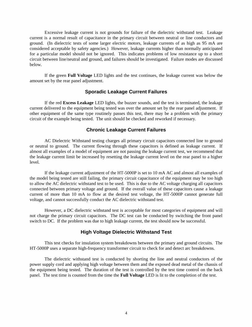
Excessive leakage current is not grounds for failure of the dielectric withstand test. Leakage
current is a normal result of capacitance in the primary circuit between neutral or line conductors and
ground. (In dielectric tests of some larger electric motors, leakage currents of as high as 95 mA are
considered acceptable by safety agencies.) However, leakage currents higher than normally anticipated
for a particular model should not be ignored. This indicates problems of low resistance up to a short
circuit between line/neutral and ground, and failures should be investigated. Failure modes are discussed
below.
If the green Full Voltage LED lights and the test continues, the leakage current was below the
amount set by the rear panel adjustment.
Sporadic Leakage Current Failures
If the red Excess Leakage LED lights, the buzzer sounds, and the test is terminated, the leakage
current delivered to the equipment being tested was over the amount set by the rear panel adjustment. If
other equipment of the same type routinely passes this test, there may be a problem with the primary
circuit of the example being tested. The unit should be checked and reworked if necessary.
Chronic Leakage Current Failures
AC Dielectric Withstand testing charges all primary circuit capacitors connected line to ground
or neutral to ground. The current flowing through these capacitors is defined as leakage current. If
almost all examples of a model of equipment are not passing the leakage current test, we recommend that
the leakage current limit be increased by resetting the leakage current level on the rear panel to a higher
level.
If the leakage current adjustment of the HT-5000P is set to 10 mA AC and almost all examples of
the model being tested are still failing, the primary circuit capacitance of the equipment may be too high
to allow the AC dielectric withstand test to be used. This is due to the AC voltage charging all capacitors
connected between primary voltage and ground. If the overall value of these capacitors cause a leakage
current of more than 10 mA to flow at the desired test voltage, the HT-5000P cannot generate full
voltage, and cannot successfully conduct the AC dielectric withstand test.
However, a DC dielectric withstand test is acceptable for most categories of equipment and will
not charge the primary circuit capacitors. The DC test can be conducted by switching the front panel
switch to DC. If the problem was due to high leakage current, the test should now be successful.
High Voltage Dielectric Withstand Test
This test checks for insulation system breakdowns between the primary and ground circuits. The
HT-5000P uses a separate high-frequency transformer circuit to check for and detect arc breakdowns.
The dielectric withstand test is conducted by shorting the line and neutral conductors of the
power supply cord and applying high voltage between them and the exposed dead metal of the chassis of
the equipment being tested. The duration of the test is controlled by the test time control on the back
panel. The test time is counted from the time the Full Voltage LED is lit to the completion of the test.
5
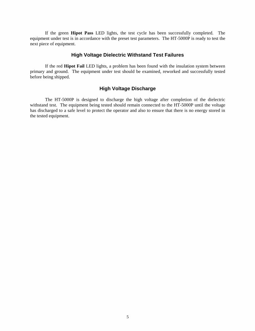
If the green Hipot Pass LED lights, the test cycle has been successfully completed. The
equipment under test is in accordance with the preset test parameters. The HT-5000P is ready to test the
next piece of equipment.
High Voltage Dielectric Withstand Test Failures
If the red Hipot Fail LED lights, a problem has been found with the insulation system between
primary and ground. The equipment under test should be examined, reworked and successfully tested
before being shipped.
High Voltage Discharge
The HT-5000P is designed to discharge the high voltage after completion of the dielectric
withstand test. The equipment being tested should remain connected to the HT-5000P until the voltage
has discharged to a safe level to protect the operator and also to ensure that there is no energy stored in
the tested equipment.

6
Section 2
Introduction and Specifications
This manual contains complete operating, maintenance and calibration instructions for the
Compliance West USA Model HT-5000P Dielectric Withstand Tester.
The instrument is a bench-type Dielectric Withstand Tester with AC or DC Output, designed for
laboratory testing of components and insulation systems.
The HT-5000P features automatic one button operation, with numerous safety features designed to
protect the operator:
- The test return lead is directly connected to ground potential for operator safety.
- In case of trouble, the test can be immediately terminated at any time by pressing the red RESET
button.
- Before the test can commence, the unit must be armed by pressing the red RESET Button. The test
will not begin until the yellow TEST Button is pushed.
- If a failure is encountered, the high voltage is immediately shut down, a buzzer sounds, and any
voltage stored in the equipment being tested is bled off by a resistor bank in the HT-5000P. The
voltage discharge progress is shown by the front panel meter.
- Failure modes are shown by the front panel LED's for quick troubleshooting.
Convenience and testing features include:
- Voltage ramp, test time and leakage limit are settable.
- Voltage ramp and test duration timer are defeatable for specialized testing.
- Testing may terminated or continued when a dielectric breakdown is detected.
- Test results are determined quickly, without operator intervention.
- Operator instructions are printed on the rear panel for quick reference.
- The HT-5000P allows custom setups for voltage ramp, test time and leakage limit.
- Voltage is discharged by a resistor bank within the HT-5000P upon test completion. Discharge
progress is shown on the front panel meter.
Your Tester is warranted for a period of one year upon shipment of the instrument to the original
purchaser.

7
Specifications
Specifications for the HT-5000P are listed in Table 1.
ELECTRICAL
Output 0-5000 Volts AC rms or 0-6000 Volts DC
Leakage Current 1-10 mA AC; 1-5 mA DC
Pass/Fail Criteria:
Leakage Current: Pass/Fail point user adjustable.
Dielectric Breakdown: Separate high frequency detection circuit for
breakdown spike detection
Test Time: User adjustable 1-60 sec., defeatable
Voltage Ramp-up Time: User adjustable 1-5 sec., defeatable
Voltage Ramp-down Time: Factory set 8 sec. maximum
Meter accuracy 2% from 500-5000 volts AC, 500-6000 volts DC
Pass/Fail Repeatability 3%
Duty cycle 100 %
Test adjustments Rear Panel: Ramp Time
Test Time
Leakage Limit
Voltage Adjust
Voltage Ramp ON/DEFEAT
Timer Duration ON/DEFEAT
Failure Shutdown ON/DEFEAT
ENVIRONMENTAL
Operating Temperature 15-40 C
Relative Humidity Range 0-90% non-condensing
GENERAL
Input power requirements See rear panel for input voltage and fuse ratings
Weight 17½ lbs.
RESET and TEST Lamp Type Replace with type 73 14V lamp.
SAFETY AGENCY TOPICS
Transformer Output < 500VA
Visual Indication of Voltage Output Provided by front panel meter, directly connected to high
voltage output
Failure Indication Audible, provided by internal buzzer
Visual, provided by red LEDs on front panel
Test can be automatically terminated on failure
Leakage Test Provided; 1 mA AC factory set pass/fail point, user adjustable.
Table 1. HT-5000P Specifications
8
Section 3
Operation
This section describes how to set up and make measurements with your tester. We recommend
that you read the entire section carefully so that you can use all of the features of your tester.
Setting up your Tester
Your tester is shipped in a special protective container that should prevent damage to the instrument
during shipping. Check the shipping order against the contents of the container and report any damage or
short shipment to Compliance West USA. The container should include the following:
- The HT-5000P Dielectric Withstand Tester
- An 18 AWG Test Lead (Alligator Clip/Banana Plug ends, black)
- An 18 AWG Line Power Cord to provide power to the HT-5000P
- An 18 AWG High Voltage Test Lead (Alligator Clip/High Voltage Plug ends, red)
- This Instruction Manual
If reshipment of the instrument is necessary, please use the original shipping container. If the
original shipping container is not available, be sure that adequate protection is provided to prevent
damage during shipment. We recommend that the instrument be surrounded by at least three inches of
shock-absorbing material on all sides of the container.
AC Line Voltage Requirements
AC line voltage requirements for your Tester are noted on the rear panel of the instrument. Do
not connect the instrument to a different voltage source.
Fuse Replacement
There is a user-replaceable fuse (F1) located on the rear panel of the instrument. It is located
behind a door in the Power Inlet-Power Switch-Fuse Holder device. The fuse rating is noted on the rear
panel. Do not attempt to replace it with a fuse of any other rating.
Use the following procedure to replace the fuse F1:
1. Turn the power switch to the O or Off position.
2. Unplug the instrument from the source of supply.
3. Remove the power inlet cord from the instrument.
4. Using a small screwdriver, pry open the fuse holder door.
5. Replace the fuse with a new one of the correct rating.
6. Replace the fuse holder door and power inlet cord.
9
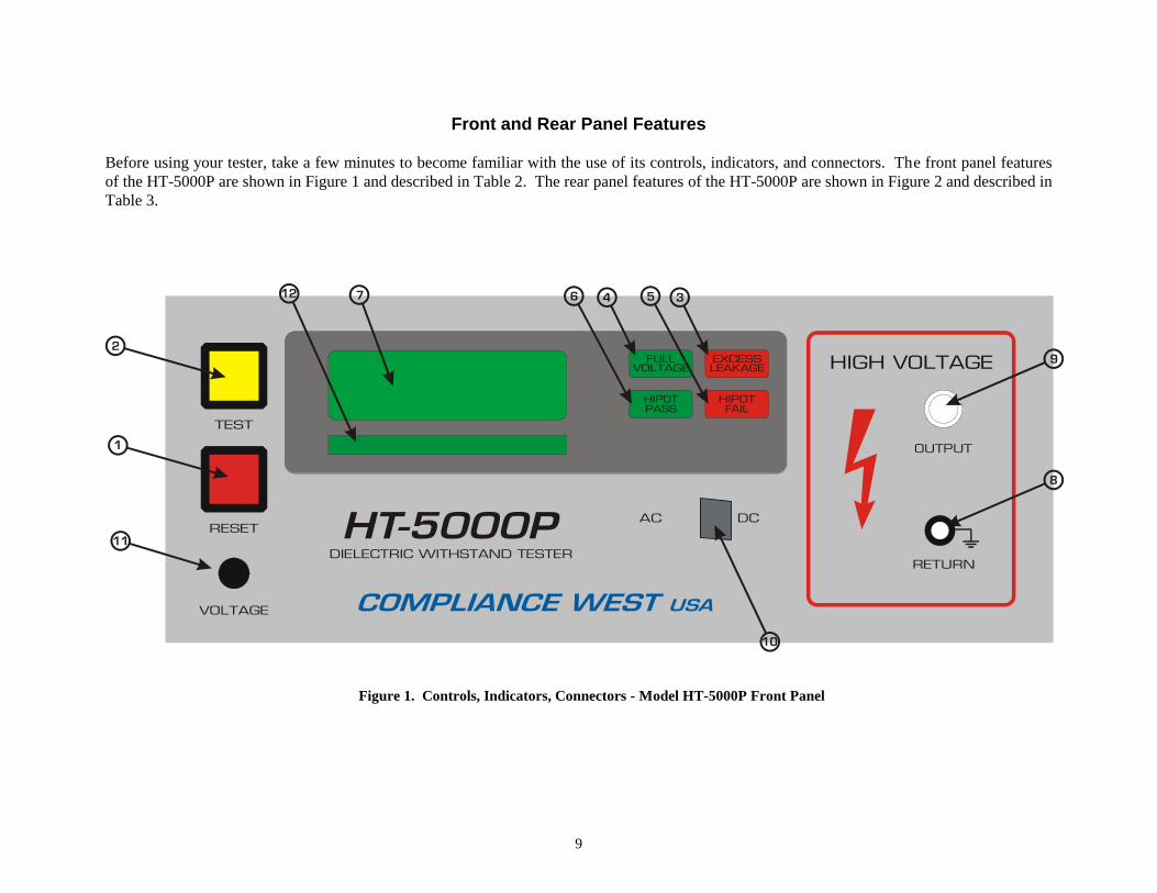
Front and Rear Panel Features
Before using your tester, take a few minutes to become familiar with the use of its controls, indicators, and connectors. The front panel features
of the HT-5000P are shown in Figure 1 and described in Table 2. The rear panel features of the HT-5000P are shown in Figure 2 and described in
Table 3.
Figure 1. Controls, Indicators, Connectors - Model HT-5000P Front Panel
10
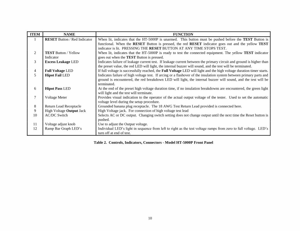
ITEM NAME FUNCTION
1 RESET Button / Red Indicator When lit, indicates that the HT-5000P is unarmed. This button must be pushed before the TEST Button is
functional. When the RESET Button is pressed, the red RESET indicator goes out and the yellow TEST
indicator is lit. PRESSING THE RESET BUTTON AT ANY TIME STOPS TEST.
2
TEST Button / Yellow
Indicator
When lit, indicates that the HT-5000P is ready to test the connected equipment. The yellow TEST indicator
goes out when the TEST Button is pressed.
3 Excess Leakage LED Indicates failure of leakage current test. If leakage current between the primary circuit and ground is higher than
the preset value, the red LED will light, the internal buzzer will sound, and the test will be terminated.
4 Full Voltage LED If full voltage is successfully reached, the Full Voltage LED will light and the high voltage duration timer starts.
5 Hipot Fail LED Indicates failure of high voltage test. If arcing or a flashover of the insulation system between primary parts and
ground is encountered, the red breakdown LED will light, the internal buzzer will sound, and the test will be
terminated.
6 Hipot Pass LED At the end of the preset high voltage duration time, if no insulation breakdowns are encountered, the green light
will light and the test will terminate.
7 Voltage Meter Provides visual indication to the operator of the actual output voltage of the tester. Used to set the automatic
voltage level during the setup procedure.
8 Return Lead Receptacle Grounded banana plug receptacle. The 18 AWG Test Return Lead provided is connected here.
9 High Voltage Output Jack High Voltage jack. For connection of high voltage test lead
10 AC/DC Switch Selects AC or DC output. Changing switch setting does not change output until the next time the Reset button is
pushed.
11 Voltage adjust knob Use to adjust the Output voltage.
12 Ramp Bar Graph LED’s Individual LED’s light in sequence from left to right as the test voltage ramps from zero to full voltage. LED’s
turn off at end of test.
Table 2. Controls, Indicators, Connectors - Model HT-5000P Front Panel
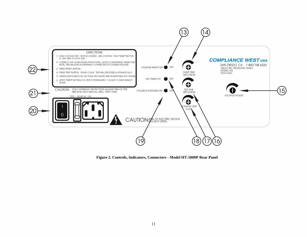
11
Figure 2. Controls, Indicators, Connectors - Model HT-5000P Rear Panel
12
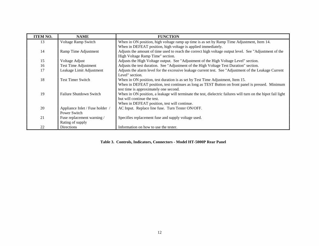
ITEM NO. NAME FUNCTION
13 Voltage Ramp Switch When in ON position, high voltage ramp up time is as set by Ramp Time Adjustment, Item 14.
When in DEFEAT position, high voltage is applied immediately.
14 Ramp Time Adjustment Adjusts the amount of time used to reach the correct high voltage output level. See "Adjustment of the
High Voltage Ramp Time" section.
15 Voltage Adjust Adjusts the High Voltage output. See "Adjustment of the High Voltage Level" section.
16 Test Time Adjustment Adjusts the test duration. See "Adjustment of the High Voltage Test Duration" section.
17 Leakage Limit Adjustment Adjusts the alarm level for the excessive leakage current test. See "Adjustment of the Leakage Current
Level" section.
18 Test Timer Switch When in ON position, test duration is as set by Test Time Adjustment, Item 15.
When in DEFEAT position, test continues as long as TEST Button on front panel is pressed. Minimum
test time is approximately one second.
19 Failure Shutdown Switch When in ON position, a leakage will terminate the test, dielectric failures will turn on the hipot fail light
but will continue the test.
When in DEFEAT position, test will continue.
20 Appliance Inlet / Fuse holder /
Power Switch
AC Input. Replace line fuse. Turn Tester ON/OFF.
21 Fuse replacement warning /
Rating of supply
Specifies replacement fuse and supply voltage used.
22 Directions Information on how to use the tester.
Table 3. Controls, Indicators, Connectors - Model HT-5000P Rear Panel
13
Factory Settings
The unit is configured as shown when shipped from Compliance West USA:
Voltage Type: AC
Leakage Current Level: 1 mA
High Voltage Ramp Time: 1 second
High Voltage Level: minimum
High Voltage Test Time: 1 second
Adjustment of the various settings are shown below.
CAUTION
High voltage is generated by the HT-5000P. Although the chassis of the equipment
under test is grounded by the HT-5000P, a risk of shock exists. Exercise care when
using the HT-5000P.
NOTE
These adjustment procedures set the use parameters of the HT-5000P. They do not take
the place of the annual calibration required by the safety agencies.
Display of Leakage Limit and Duration settings
To verify the Test Duration and Leakage Limit current settings, hold down the RESET button
for 2 seconds. The meter will display “L” with the Leakage Limit value in mA. Hold down the RESET
button again for 2 seconds and the meter will display “d” with the Test Duration set time in seconds.
Adjustment of the Leakage Current Level
1. AC Leakage Current can be set from 1.0 to 10.0 mA. DC Leakage Current can be set from 1.0 to
5.0 mA. To set the leakage limit follow the steps below.
2. Connect the HT-5000P to a correctly rated source of supply and turn the power switch to the I or
ON position. Push the RESET button. The yellow TEST indicator should light, indicating that the
HT-5000P is ready to test.
3. Use the AC/DC button to select the type of output voltage.
4. On the rear panel turn the Leakage Limit potentiometer. As soon as the potentiometer starts
turning, the meter will start blinking, display “L”, and the value can be set in 0.1 mA increments
from 1.0 to 10.0 mA AC or 1.0 to 5.0 mA DC depending on which mode you are in, AC or DC.
5. If tamperproof settings are desired, the Leakage Limit control shaft may be pulled away with a
slight tug. (It may be reinserted for future adjustments.)
Adjustment of the High Voltage Ramp Time
This procedure controls the amount of time used to ramp the high voltage to the required level. The
factory setting of 1 second is adequate for most situations. Use this procedure if adjustment to a different
ramp time within the range of <1-5 seconds is required.
14
1. Connect the HT-5000P to a correctly rated source of supply and turn the power switch to the I or
ON position. Push the RESET button. The yellow TEST indicator should light, indicating that the
HT-5000P is ready to test.
2. Make sure there are no test leads connected to the HT-5000P. Push the TEST button.
3. When the TEST button is pressed, the voltage will ramp and hold. Adjust the Ramp Time control
on the rear panel until the desired ramp time is reached. The test can be terminated at any time by
pressing the RESET button.
4. If tamperproof settings are desired, the Ramp Time control shaft may be pulled away with a slight
tug. (It may be reinserted for future adjustments.)
Adjustment of the High Voltage Level
This procedure controls the high voltage level used in the dielectric withstand test.
1. Adjust the Test Time control to approximately the middle of its travel.
2. Connect the HT-5000P to a correctly rated source of supply and turn the power switch to the I or
ON position. Push the RESET button. The yellow TEST indicator should light, indicating that the
HT-5000P is ready to test.
3. Use the AC/DC button to select the type of output voltage.
4. Make sure there are no test leads connected to the Tester. Push the TEST button.
5. After the TEST button is pressed, the voltage will ramp and hold. Set the Voltage Adjust control
on the rear panel to the desired voltage.
6. Reset the test time using the procedure Adjustment of the High Voltage Test Time.
Adjustment of the High Voltage Test Time
This procedure sets the length of time the HT-5000P will conduct the high voltage test.
1. Connect the HT-5000P to a correctly rated source of supply and turn the power switch to the I or
ON position. Push the RESET button. The yellow TEST indicator should light, indicating that the
HT-5000P is ready to test.
2. On the rear panel turn the Test Time potentiometer. As soon as the potentiometer starts turning,
the meter will display “d” and the value can be set in 1second increments from 1 to 60 seconds.
3. If tamperproof settings are desired, the Leakage Limit control shaft may be pulled away with a
slight tug. (It may be reinserted for future adjustments.)
Setting the Rear Panel Switches
The table 4 represents the rear panel switches position use this table in conjunction with table 5 to
define the desired operation of the HT-5000P.

15
Voltage Ramp
ON
DEFEAT
ON
DEFEAT
DEFEAT
Test Timer
ON
ON
DEFEAT
DEFEAT
DEFEAT
Failure Shutdown
ON
ON
ON
ON
DEFEAT
Condition
A
B
C
D
E
Table 4. Rear Panel Switch Truth Table.
A
Fully automatic operation. When Test button is pressed, the output voltage will ramp at a rate
determined by the position of the TEST TIME adjustment knob. Test will stop automatically on all
leakage or breakdown failures.
B
Voltage Ramp is defeated. Same as (A) above except that full voltage is produced at the output
immediately. Test will stop automatically on all leakage or breakdown failures. For safety, we
recommend that you begin testing with the front panel voltage knob set at minimum.
C
Test Timer is defeated. Same as (A) above except that after full voltage is reached, the test will continue
only as long as the Test button is held in, minimum one second. Test will stop automatically on all
leakage or breakdown failures.
D
Voltage Ramp and Test Timer are defeated. Full voltage is produced at the output immediately when the
Test button is pressed. The test will continue only as long as the Test button is held in, minimum one
second. Test will stop automatically on all leakage or breakdown failures. For safety, we recommend
that you begin testing with the front panel voltage knob set at minimum.
E
Total Defeat. Full voltage is produced at the output immediately. Test will continue only as long as the
TEST button is held in. The HT-5000P will not shut down on a leakage or dielectric failure, but the
front panel Excess Leakage or Hipot Fail lights will indicate a failure. The Hipot Pass light will not light
at the completion of a successful test. For safety, we recommend that you begin testing with the front
panel voltage knob set at minimum.
WARNING: Testing with the shutdown defeated is extremely hazardous. The HT-5000P can
generate lethal levels of voltage and current. Therefore, care should be taken when examining the
equipment being tested to locate areas of failure while the HT-5000P is operating. Do not operate
the HT-5000P for extended periods under conditions of excess leakage or dielectric breakdown, as
overheating and/or damage to the equipment being tested may result.
NOTE
All undefined states will defeat HT-5000P operation. Buzzer will sound.
Table 5. Rear Panel Switch Condition Table.

16
Operating Techniques
The following paragraphs describe how to operate your HT-5000P Dielectric Withstand Tester.
CAUTION:
High voltage is generated by the HT-5000P. Although the chassis of the equipment under
test is grounded by the HT-5000P, a risk of shock exists. Exercise care when using the
HT-5000P.
Operation Test
The following procedure will verify that the HT-5000P is working correctly. We recommend
that this procedure be conducted periodically to ensure proper operation of the tester.
CAUTION
High voltage (up to 5000 Volts AC and 6000 Volts DC) generated by the HT-5000P is
exposed during this test. A risk of shock exists. Exercise care when using the HT-
5000P.
1. Turn the Tester on using the AC Power switch.
2. Set the Voltage Ramp switch, Test Timer switch, and Failure Shutdown switch to ON position.
3. Disconnect leads from the Output and Return jacks.
4. Set the Test Time to 15 seconds.
5. Push the RESET button. The TEST button should light.
6. Push the TEST button.
7. The HT-5000P tester will conduct a test. The meter will read a voltage, hold, and return to zero.
During the test, the voltage can be adjusted using the Voltage Adjustment knob. At the end of the
test, the Full Voltage, Hipot Pass, and RESET switch indicators should be lit.
8. Connect the red lead to the Output receptacle, and the black lead to the Return receptacle.
9. Connect the two leads together to simulate a high leakage current condition. Push the RESET button
and then push the TEST button.
10. Test should terminate immediately and the buzzer should sound. The Excess Leakage Indicator and
RESET button indicators should be lit. If a spark occurred, the Hipot Fail indicator will also be lit.
11. Leaving the red and black leads connected together, disconnect the red lead from the HT-5000P.
12. Enable the voltage output by pressing the RESET button, then the TEST button. When the full
voltage indicator lights, adjust the Voltage knob so the output is approx. 1500 volts. Press the
RESET button to disable high voltage output.
13. Verify that the red and black leads are connected together, the black lead is connected to the Return
receptacle, and the red lead is disconnected from the HT-5000P.
14. (This test simulates a dielectric breakdown. High voltage could exist on the alligator clips.
Exercise caution to avoid shock.) Push the RESET button, then the TEST button. After the full
voltage indicator lights, pick up the red lead and insert it into the HV Output. The test will
immediately terminate with a buzzer. The Full Voltage, Hipot Fail, and RESET button indicators
should be lit.
15. Adjust the voltage and time to the desired settings
Passage of these tests indicates that the HT-5000P is functioning properly and that it is safe to
use. If the results of the performance test are not in accordance with the above, service is required.
Remove the HT-5000P from service and contact Compliance West USA, Inc. for servicing information.
17
Testing
This section describes how the HT-5000P is used to conduct a hipot test. Before continuing, we
recommend that you read Section 1, "An Introduction to Dielectric Withstand Testing with the HT-
5000P". It contains valuable safety, operation, and test result evaluation information which can help you
conduct the test safely and correctly. The test can be stopped immediately at any time by pressing the red
RESET button on the front panel.
Example Test Procedure:
1. Connect the HT-5000P to a correctly rated source of supply and turn the power switch to the I or
ON position. Push the RESET button. The yellow TEST indicator should light, indicating that the
HT-5000P is ready to test.
2. Plug the black return lead into the Return receptacle on the front panel of the HT-5000P.
3. Plug the red high voltage lead into the Output receptacle on the front panel of the HT-5000P.
4. Connect the alligator clip end of the black return lead to an exposed metal part on the chassis of the
equipment to be tested.
5. Connect the alligator clip end of the red output lead to the current carrying conductors of the DUT
and make sure the power switch on the equipment being tested is in the 1 or ON position (if
applicable).
6. Push the TEST button. The HT-5000P will:
a. Ramp the voltage at the rate set by the Ramp Time procedure.
-If leakage current between the AC pins of the power supply cord (or point attached to
the high voltage lead) and the chassis ground of the unit rises above the value set by the
Leakage Limit procedure, the red Excess Leakage LED will light, the buzzer will sound,
and the test will terminate.
-If the leakage current level is below the set level when the high voltage set by the High
Voltage Level procedure is reached, the green Full Voltage LED will light and the test
will continue.
b. Conduct the high voltage test for the amount of time set in the Test Duration procedure.
-If a breakdown of the insulation system between primary voltage and ground is detected,
the red Hipot Fail LED will light, the buzzer will sound, and the test will terminate.
If no breakdown is detected, the high voltage will be bled off, the green Hipot Pass LED
will light, and the red RESET switch will light.
7. For safety, the operator should not disconnect the cords until the Hipot Pass LED is lit and the
reading on the front panel voltage meter has dropped to zero. This will ensure that the test voltage
has been bled off.
8. The operator can now remove the equipment from the HT-5000P and connect another. The HT-
5000P should then be armed by pressing the red RESET button. When ready, the operator then
presses the yellow TEST button and the test procedure will be conducted again.
18
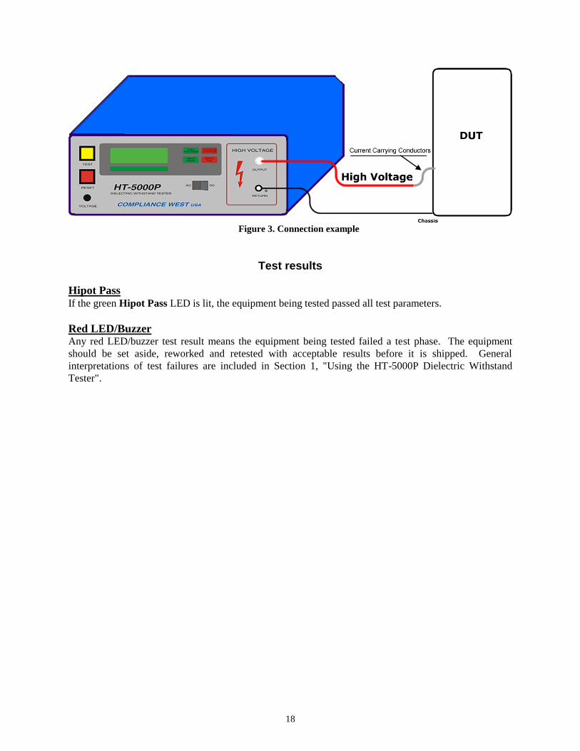
Figure 3. Connection example
Test results
Hipot Pass If the green Hipot Pass LED is lit, the equipment being tested passed all test parameters.
Red LED/Buzzer Any red LED/buzzer test result means the equipment being tested failed a test phase. The equipment
should be set aside, reworked and retested with acceptable results before it is shipped. General
interpretations of test failures are included in Section 1, "Using the HT-5000P Dielectric Withstand
Tester".

19
Section 4
Technical Assistance
Technical Assistance from Compliance West USA is available:
Phone: (800) 748-6224
Hours: 8:00 AM - 4:00 PM Pacific Time.
Also available on our web site at: www.compwest.com
Contact:
Compliance West USA
650 Gateway Center Way, Suite D
San Diego, CA., 92102
United States of America.
Phone: (619) 878-9696
FAX: (619) 794-0404

20
Section 5
Maintenance and Calibration
WARNING
THESE SERVICE INSTRUCTIONS ARE FOR USE BY QUALIFIED PERSONNEL ONLY. TO
AVOID ELECTRIC SHOCK, DO NOT PERFORM ANY SERVICING OTHER THAN THAT
CONTAINED IN THE OPERATING INSTRUCTIONS UNLESS YOU ARE QUALIFIED TO DO
SO.
Introduction
This section of the manual contains maintenance information for the HT-5000P Dielectric
Withstand Tester. This maintenance information is divided into service information, general
maintenance, a performance test, and a calibration procedure. The performance test is recommended as
an acceptance test when the instrument is first received, and later as a preventative maintenance tool to
verify proper instrument operation. A 1-year calibration cycle is recommended to maintain the
specifications given in Section 1. The test equipment required for the calibration procedure is a DMM
able to read true rms 0-5000 Vac 1%, 0-6000 Vdc 1%.
Service Information
The HT-5000P is warranted to the original purchaser for a period of 1 year. This warranty does
not cover problems due to misuse or neglect.
Malfunctions which occur within the limits of the warranty will be corrected at no charge. Mail
the instrument post paid to the manufacturer. Dated proof of purchase is required for all in-warranty
repairs.
The manufacturer is also available for calibration and/or repair of instruments that are beyond
their warranty period. Contact the manufacturer for a cost quotation. Ship the instrument and your
remittance according to the instructions given by the manufacturer.
General Maintenance
Interior Access
NOTE
To avoid contaminating the PWB with oil from your fingers, handle it by the edges or wear gloves. If the
PWB becomes contaminated, refer to the cleaning procedures given later in this section.
21
Calibration Access
Use the following procedures to gain access to the calibration adjustments of your instrument.
1. Set Line Power switch to OFF.
2. Disconnect the power cord from the rear of the instrument.
3. Remove the two upper screws on each side of the unit.
4. Grasp the top of the enclosure clamshell and lift it off the front and rear panels.
5. All calibration adjustments are now accessible.
6. To reassemble, reverse steps 1-5 above.
WARNING
Dangerous voltages exist when energized. Exercise extreme care when working on an
energized circuit.
Cleaning
CAUTION
Do not use aromatic hydrocarbons or chlorinated solvents for cleaning. These
solutions will react with the plastic materials used in the instrument.
Clean the front panel and case with a mild solution of detergent and a damp sponge. Clean dust from the
PWB with clean, dry, low pressure (<20 psi).
Calibration Procedure
The Calibration Procedure should be performed annually and any time your instrument has been
repaired. The calibration procedure consists of two parts:
1) The Voltage Calibration adjustment calibrates the voltage output to agree with the meter reading.
2) The Current Calibration adjustment calibrates the current output used for the leakage limit.
NOTE
Allow the instrument to stabilize for approximately five minutes. Perform all calibration
adjustments at an ambient temperature of 23 C 5 C (73 F 9 F).
WARNING
CALIBRATION ADJUSTMENTS ARE PERFORMED ON ENERGIZED CIRCUITS.
EXERCISE CAUTION AT ALL TIMES, AND USE A NON-CONDUCTIVE TOOL FOR ALL
ADJUSTMENTS.

22
Calibration and Software Version Information
This will allow the user to see the version of the software as well as who performed the last calibration.
1. Turn off the HT-5000P tester.
2. Hold in the Reset button while turning on the tester.
3. The meter will display 3 items:
A) The model number of the tester, 5000.
B) The version of the software
C) Laboratory number to designate who performed the last calibration:
(1= Compliance West USA, 2= another company)
Voltage Calibration Adjustment
Use the following procedure to calibrate the output voltage.
1. Ensure that all test leads are removed from the HT-5000P.
2. Turn OFF the HT-5000P tester.
3. To enter the Calibration Mode you MUST follow the following sequence:
- Hold in both the Test and Reset buttons.
- Turn on the HT-5000P tester.
- Release the Test button, release the Reset button, press and hold the Reset button, press and hold
the Test button, release the Test button, and then release the Reset button.
4. If the correct sequence was entered, the display will read "Sure", if not, start again at step 2 above.
5. While "Sure" is displayed on the screen you can:
A) Press Reset to exit out of the Calibration Mode and keep all of the currently programmed
calibration settings or
B) Press Test to enter the Calibration Mode and create new calibration settings. (Be sure you
want to enter the Calibration Mode as this will change the laboratory number so it will show the
calibration was not performed by Compliance West USA).
6. Once the Calibration Mode has been entered, the Reset button toggles between the 6 calibration
menus: Volt, V1, V2, L1, L2, and bars. Make sure "V1" is displayed on the meter.
7. Hook up a calibrated 1000:1 voltage probe and a calibrated DMM between the Output receptacle
and the Return jack on the front panel.
8. Use the AC/DC selector switch on the front panel to choose which voltage will be calibrated.
9. Turn the Voltage Adjust on the front panel to minimum (counterclockwise). Press the Test button
and a voltage number will be displayed on the front panel meter (4500 for AC or 6000 for DC). Be
careful as the HT-5000P will be putting out voltage at this point.
10. Turn the Voltage Adjust on the rear panel clockwise until the output on the DMM equals the
appropriate voltage (4500 volts AC or 6000 volts DC) and press the Test button. The display will
now display "V1" again.
11. Press the Reset button until "V2" is displayed on the front panel meter.
12. Turn the Voltage Adjust on the front panel to minimum (counterclockwise). Press the Test button
and 500 will be displayed on the front panel meter (for either AC and DC). Be careful as the HT-
5000P will be putting out voltage at this point.
13. Turn the Voltage Adjust on the rear panel clockwise until the output on the DMM equals the
appropriate voltage (500 volts AC or DC) and press the Test button. The display will now display
"V2" again. The voltage is now be calibrated.
14. Turn Off the HT-5000P tester.

23
15. The voltage can be verified by turning on the HT-5000P, running a test, and using the 1000:1
voltage probe to check the meter at different voltages. If the voltages are not within +/- 2% at each
voltage, the voltage calibration must be performed again starting at step 1 above.
Figure 4. Connection for Voltage Adjustment
Current Calibration Adjustment
1. You must be in Calibration Mode as in step 3 under the Voltage Calibration Adjustment above.
2. Use the AC/DC selector switch on the front panel to choose AC.
3. Turn the Voltage Adjust on the front panel to minimum (counterclockwise).
4. Connect the output of the HT-5000P through a 60K ohm, 100 watt high voltage resistor in series
with a calibrated DMM capable of measuring 10.0mA AC and returning to the Return jack on the
front panel of the HT-5000P.
5. In the calibration mode, hit the Reset button until "L1" is displayed on the front panel.
6. Once "L1" is displayed, press the Test button once and 8.0 will be displayed.
7. Slowly increase the variac watching the current flowing on the DMM. Adjust the variac until
8.0mA AC is displayed on the DMM and then press the Test button.
8. The display will show "hold".
9. Wait until the display returns to "L1".
10. Turn the Voltage Adjust on the rear panel to minimum (counterclockwise).
11. In the calibration mode, hit the Reset button until "L2" is displayed on the front panel.
12. Once "L2" is displayed, press the Test button once and 1.0 will be displayed.
13. Slowly increase the variac watching the current flowing on the DMM. Adjust the variac until
1.0mA AC is displayed on the DMM and then press the Test button.
14. The display will show "hold".
15. Wait until the display returns to "L2". At this point the AC leakage current is calibrated.
16. Use the AC/DC selector switch on the front panel to choose DC.
17. Connect the output of the HT-5000P through a 240K ohm, 100 watt high voltage resistor in series
with a calibrated DMM capable of measuring 5.0mA DC and returning to the Return jack on the
front panel of the HT-5000P.
18. In the calibration mode, hit the Reset button until "L1" is displayed on the front panel.
19. Once "L1" is displayed, press the Test button once and 5.0 will be displayed.
20. Slowly increase the variac watching the current flowing on the DMM. Adjust the variac until
5.0mA DC is displayed on the DMM and then press the Test button.
24
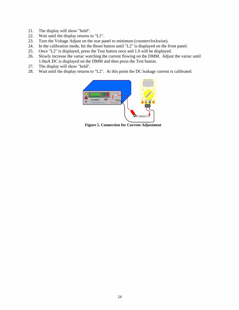
21. The display will show "hold".
22. Wait until the display returns to "L1".
23. Turn the Voltage Adjust on the rear panel to minimum (counterclockwise).
24. In the calibration mode, hit the Reset button until "L2" is displayed on the front panel.
25. Once "L2" is displayed, press the Test button once and 1.0 will be displayed.
26. Slowly increase the variac watching the current flowing on the DMM. Adjust the variac until
1.0mA DC is displayed on the DMM and then press the Test button.
27. The display will show "hold".
28. Wait until the display returns to "L2". At this point the DC leakage current is calibrated.
Figure 5. Connection for Current Adjustment