instruction manual - hobbico, inc.manuals.hobbico.com/top/topa0951-manual.pdf · in no case shall...
TRANSCRIPT

™
READ THROUGH THIS MANUAL BEFORE STARTING CONSTRUCTION. IT CONTAINS IMPORTANT INSTRUCTIONS AND WARNINGS CONCERNING THE ASSEMBLY AND USE OF THIS MODEL.Entire Contents © 2011 Hobbico®, Inc. TOPA0951 Mnl
WARRANTYTop Flite® Model Manufacturing Co. guarantees this kit to be free from defects in both material and workmanship at the date of purchase. This warranty does not cover any component parts damaged by use or modification. In no case shall Top Flite’s liability exceed the original cost of the purchased kit. Further, Top Flite reserves the right to change or modify this warranty without notice.
In that Top Flite has no control over the final assembly or material used for final assembly, no liability shall be assumed nor accepted for any damage resulting from the use by the user of the final user-assembled product. By the act of using the user-assembled product, the user accepts all resulting liability.
If the buyer is not prepared to accept the liability associated with the use of this product, the buyer is advised to return this kit immediately in new and unused condition to the place of purchase.
To make a warranty claim send thedefective part or item to HobbyServices at this address:
Include a letter stating your name, return shipping address, as much contact information as possible (daytime telephone number, fax number, e-mail address), a detailed description of the problem and a photocopy of the purchase receipt. Upon receipt of the package the problem will be evaluated as quickly as possible.
Hobby Services3002 N. Apollo Dr. Suite 1Champaign IL 61822 USA
SPECIFICATIONS
INSTRUCTIONMANUAL
Wingspan: 62.5 in [1590mm]
Wing Area: 699 sq in [45.1 dm2]
Weight: 8.5– 9.5 lb[3850– 4310 g]
WingLoading:
28– 31 oz/sq ft[85–95 g/dm2]
Length: 50.5 in[1285mm]
Radio: 5– 6 channel, 7– 8 servos
Engine: .61 cu in [10.0cc]two-stroke glow,.91 cu in [15.0cc]four-stroke glow
Top Flite Models Champaign, ILPh: (217) 398-8970, Ext. 5Fax: (217) 398-7721

2
INTRODUCTION
Thank you for purchasing the Top Flite Gold Edition 1/8th-scale F4-U Corsair .60 ARF. In spite of the apparent complication of the gull-wing design and the scale appearance, you’ll fi nd that the Corsair assembles more quickly than expected. The fl aps and ailerons are pre-hinged and the outer fl aps join to the inner fl aps with convenient tabs. Detailed instructions and illustrations of various motor installations will get you into the air in little time. Finally, the Corsair’s light weight and generous wing area just about make it a trainer. But we won’t tell if you won’t tell, and all the spectators will think you’re a pro!
For the latest technical updates or manual corrections to this model visit the Top Flite web site at www.top-fl ite.com. Open the “GOLD EDITION ARFS” link on the left side of the page and click on image of the Corsair that appears. If there is new technical information or changes, you’ll see an “Important! TECH NOTICE” box on the upper left corner of the page. Click on the Tech Notice box to read the info.
SCALE COMPETITION
The scale of this model is 1/8th (or 13% – 1/7.7 to be precise). These fi gures were derived from comparing the wingspan of this model to the wingspan of the full-size. Though the Top Flite F4-U Corsair is an ARF and may not have the same level of detail as an “all-out” scratch-built competition model, it is a scale model nonetheless and is therefore eligible to compete in the Fun Scale class in AMA competition (we receive many favorable reports of our ARFs in scale competition!). In Fun Scale, the “builder of the model” rule does not apply. To receive the fi ve points for scale documentation, the only proof required that a full size aircraft of this type in this paint/markings scheme did exist is a single sheet such as a kit box cover from a plastic model, a photo, or a profi le painting, etc. If a black-and-white photo is used, other written documentation of color must be provided. Contact the AMA for a rule book with full details. See page 3 for the AMA contact information.
INTRODUCTION . . . . . . . . . . . . . . . . . . . . . . . . . . 2 Scale Competition . . . . . . . . . . . . . . . . . . . . . . . 2 AMA . . . . . . . . . . . . . . . . . . . . . . . . . . . . . . . . . . 3SAFETY PRECAUTIONS . . . . . . . . . . . . . . . . . . . 3DECISIONS YOU MUST MAKE . . . . . . . . . . . . . . . 3 Engine Recommendations . . . . . . . . . . . . . . . . . 3 Retractable Landing Gear . . . . . . . . . . . . . . . . . 4 Radio Equipment . . . . . . . . . . . . . . . . . . . . . . . . 4ADDITIONAL ITEMS REQUIRED . . . . . . . . . . . . . 4 Hardware and Accessories . . . . . . . . . . . . . . . . 4 Adhesives and Building Supplies . . . . . . . . . . . . 4 Optional Supplies and Tools. . . . . . . . . . . . . . . . 4 Covering Tools . . . . . . . . . . . . . . . . . . . . . . . . . . 5KIT INSPECTION. . . . . . . . . . . . . . . . . . . . . . . . . . 5ORDERING REPLACEMENT PARTS . . . . . . . . . . 5KIT CONTENTS . . . . . . . . . . . . . . . . . . . . . . . . . . . 6PREPARATION . . . . . . . . . . . . . . . . . . . . . . . . . . . 6 Prepare the Covering . . . . . . . . . . . . . . . . . . . . . 6ASSEMBLE THE WING . . . . . . . . . . . . . . . . . . . . . 7 Install the Belly Pan & Air Intakes . . . . . . . . . . . 7 Hook Up the Flaps and Ailerons . . . . . . . . . . . . 9 Join the Wing Panels . . . . . . . . . . . . . . . . . . . . 10 Install the Retractable Landing Gear . . . . . . . . . . 11 Mount the Fixed Landing Gear. . . . . . . . . . . . . 14ASSEMBLE THE FUSELAGE . . . . . . . . . . . . . . . 14 Install the Rudder . . . . . . . . . . . . . . . . . . . . . . . 14 Mount the Horizontal Stabilizer . . . . . . . . . . . . 16 Install the Elevators . . . . . . . . . . . . . . . . . . . . . 18
Install the Tail Gear Cover . . . . . . . . . . . . . . . . 18 Mount the Engine . . . . . . . . . . . . . . . . . . . . . . . 19 Install the Fuel Tank . . . . . . . . . . . . . . . . . . . . . 22 Mount the Cowl . . . . . . . . . . . . . . . . . . . . . . . . 22 Install the Replica Engine. . . . . . . . . . . . . . . . . 24 Final Radio/Retract Installation . . . . . . . . . . . . 25 Install the Cockpit . . . . . . . . . . . . . . . . . . . . . . . 26 Apply the Decals . . . . . . . . . . . . . . . . . . . . . . . 27GET THE MODEL READY TO FLY . . . . . . . . . . . 27 Balance the Model (C.G.). . . . . . . . . . . . . . . . . 27 Balance the Model Laterally. . . . . . . . . . . . . . . 28PREFLIGHT . . . . . . . . . . . . . . . . . . . . . . . . . . . . . 28 Check the Control Directions . . . . . . . . . . . . . . 28 Set the Control Throws. . . . . . . . . . . . . . . . . . . 28 Identify Your Model . . . . . . . . . . . . . . . . . . . . . . 29 Charge the Batteries . . . . . . . . . . . . . . . . . . . . 29 Balance Propellers . . . . . . . . . . . . . . . . . . . . . . 29 Ground Check . . . . . . . . . . . . . . . . . . . . . . . . . 29 Fuel Mixture Adjustments. . . . . . . . . . . . . . . . . 29 Range Check . . . . . . . . . . . . . . . . . . . . . . . . . . 30ENGINE SAFETY PRECAUTIONS . . . . . . . . . . . 30AMA SAFETY CODE (excerpts). . . . . . . . . . . . . 30 General . . . . . . . . . . . . . . . . . . . . . . . . . . . . . . 30 Radio Control . . . . . . . . . . . . . . . . . . . . . . . . . . 30CHECK LIST . . . . . . . . . . . . . . . . . . . . . . . . . . . . 31FLYING. . . . . . . . . . . . . . . . . . . . . . . . . . . . . . . . . 31LANDING GEAR DIAGRAM . . . . . . . . . . . . . . . . 32THROTTLE PUSHROD HOLE TEMPLATE . . . . . 33COWL HOLE TEMPLATE . . . . . . . . . . . . . . . . . . 35
TABLE OF CONTENTS

3
If you would like photos of a full-size F4-U for scale documentation, or if you would like to study the photos to add more scale details, photo packs are available from:
Bob’s Aircraft Documentation3114 Yukon Ave Ph: (714) 979-8058Costa Mesa, CA 92626 Fx: (714) 979-7279
e-mail: www.bobsairdoc.comAMA
We urge you to join the AMA (Academy of Model Aeronautics) and a local R/C club. The AMA is the governing body of model aviation and membership is required to fl y at AMA clubs. Though joining the AMA provides many benefi ts, one of the primary reasons to join is liability protection. Coverage is not limited to fl ying at contests or on the club fi eld. It even applies to fl ying at public demonstrations and air shows. Failure to comply with the Safety Code (excerpts printed in the back of the manual) may endanger insurance coverage. Additionally, training programs and instructors are available at AMA club sites to help you get started the right way. There are over 2,500 AMA chartered clubs across the country. Contact the AMA at the address or toll-free phone number below.
Academy of Model Aeronautics5151 East Memorial DriveMuncie, IN 47302-9252
Ph. (800) 435-9262Fx (765) 741-0057
Or via the Internet at: http://www.modelaircraft.org
IMPORTANT!!! Two of the most important things you can do to preserve the radio controlled aircraft hobby are to avoid fl ying near full-scale aircraft and avoid fl ying near or over groups of people.
SAFETY PRECAUTIONSPROTECT YOUR MODEL, YOURSELF & OTHERS.....FOLLOW THESE IMPORTANT SAFETY PRECAUTIONS
1. Your Top Flite F4-U Corsair ARF should not be considered a toy, but rather a sophisticated, working
model that functions very much like a full-size airplane. Because of its performance capabilities, the Corsair, if not assembled and operated correctly, could possibly cause injury to yourself or spectators and damage to property.
2. You must assemble the model according to the instructions. Do not alter or modify the model, as doing so may result in an unsafe or unfl yable model. In a few cases the instructions may differ slightly from the photos. In those instances the written instructions should be considered as correct.
3. You must take time to build straight, true and strong.
4. You must use an R/C radio system that is in fi rst-class condition, and a correctly sized engine and components (fuel tank, wheels, etc.) throughout the building process.
5. You must correctly install all R/C and other components so that the model operates correctly on the ground and in the air.
6. You must check the operation of the model before every fl ight to insure that all equipment is operating and that the model has remained structurally sound. Be sure to check clevises or other connectors often and replace them if they show any signs of wear or fatigue.
7. If you are not an experienced pilot or have not fl own this type of model before, we recommend that you get the assistance of an experienced pilot in your R/C club for your fi rst fl ights. If you’re not a member of a club, your local hobby shop has information about clubs in your area whose membership includes experienced pilots.
8. While this kit has been fl ight tested to exceed normal use, if the plane will be used for extremely high stress fl ying, or if engines larger than ones in the recommended range are used, the modeler is responsible for taking steps to reinforce the high stress points and/or substituting hardware more suitable for the increased stress.
9. WARNING: Some of the parts in this kit are made of fi berglass, the fi bers of which may cause eye, skin and respiratory tract irritation. Never blow into
one of these parts to remove fi berglass dust, as the dust will blow back into your eyes. Always wear safety goggles, a particle mask and rubber gloves when grinding, drilling and sanding fi berglass parts. Vacuum the parts and the work area thoroughly after working with fi berglass parts.
We, as the kit manufacturer, provide you with a top quality, thoroughly tested kit and instructions, but ultimately the quality and fl yability of your fi nished model depends on how you build it; therefore, we cannot in any way guarantee the performance of your completed model, and no representations are expressed or implied as to the performance or safety of your completed model.
Remember: Take your time and follow the instructions to end up with a well-built model that is straight and true.
DECISIONS YOU MUST MAKE
This is a partial list of items required to fi nish this model that may require planning or decision making before starting assembly. Order numbers are provided in parentheses.
ENGINE RECOMMENDATIONS
As specifi ed on the cover of this instruction manual, the Corsair is designed for a .61 cu in [10.0cc] two-stroke or .91 cu in [15.0cc] four-stroke glow engine. And the Corsair has the lightest airframe and wing loading of all the “Gold” ARFs to date, so there is defi nitely no need to overpower this model.
If using the O.S.® Max .65AX 2-stroke, the stock muffl er may be used, but the O.S. #744B muffl er extension (OSMG2582) or the Bisson Pitts-style muffl er (BISG4061) will be required. If using the O.S. Max .91S II 4-stroke engine, an O.S. FS70-91 Exhaust Header Pipe (OUT) (OSMG2625) is also required. If using the O.S. .95V, the M11 in-cowl 80D header pipe was also used (OSMG2568). Refer to the Engine Mounting instructions starting on page 19 for more information and illustrations.

4
For the O.S. .91 4-stroke a 15 × 6 propeller is usually the standard, “go-to” prop. However, a Master Air Screw 14 × 7 prop is a nice 3-blade option for static scale effect. In the air, the 14 × 7 loads the engine a little more than the 15 × 6 and the Corsair fl ies slightly slower, but as long as the engine is needled correctly the 14 × 7 will provide great performance.
RETRACTABLE LANDING GEAR
The Top Flite Corsair .60 ARF comes equipped with 5.0mm fi xed landing gear wires, but Robart pneumatic retracts may be used instead.
For Robart retractable landing gear the following items are required:
❍ 615 100 Degree Rotating Mains (ROBQ1815)❍ 188VR Standard Air Control Kit (ROBQ2302)❍ 190 Air Line Quick Disconnects (ROBQ2395)❍ Great Planes® Wire Axle 2x3/16" (2)
(GPMQ4282)❍ Great Planes 3/16" wheel collars (GPMQ4308)❍ K&S 7/32" brass tubing (for wheel spacers for
included wheels) (K+SR5130)
An air pump will also be required to fi ll the onboard air cylinder when you get to the fi eld and it’s time to fl y. The Robart Hand Pump & Gauge (ROBQ2363) may be used, but those who fl y often usually prefer an electric hobby/emergency air compressor with a pressure gauge. A wide selection of 12V pumps should be available at most automotive stores. Use air line
that came with the retracts to connect the fi ller valve to the compressor.
RADIO EQUIPMENT
If fl ying the Corsair with fi xed landing gear, a fi ve-channel radio with seven servos will be required; 2 ailerons, elevator, throttle, rudder and 2 fl aps. If installing retracts, six channels will be required with an eighth servo.
For all fl ight control surfaces, servos with a minimum of 50 oz. in. of torque (such as Futaba® 9001—FUTM0075) should be used. For the throttle and the air control valve, any standard servo is suitable (such as Futaba S3003—FUTM0031).
Note: The servo output torque recommendations are the minimums. Higher-torque, ball bearing servos could be used for durability and fl ight precision.
The following servo extensions and Y-harnesses were also used:
❍ (2) 24" [600mm] servo extensions for the aileron servos (HCAM2721 for Futaba)
❍ (2) 6" [150mm] servo extensions for connecting the fl aps and ailerons to the receiver (HCAM2701 for Futaba)
❍ (2) Futaba dual servo connectors for the fl ap and aileron servos (FUTM4130)
❍ A minimum 1,000mAh receiver battery is also recommended.
ADDITIONAL ITEMS REQUIRED
HARDWARE AND ACCESSORIES
In addition to the items listed in the “Decisions You Must Make” section, following is the list of hardware and accessories used to fi nish the Corsair as illustrated in this instruction manual. Order numbers are provided in parentheses.
❍ 1/4" R/C foam rubber (HCAQ1000)❍ 3' [900mm] standard silicone fuel tubing
(GPMQ4131)
❍ 1/2" [13mm] double-sided foam mounting tape (GPMQ4440)
❍ Ernst #124 Charge Receptacle (ERNM3001 for Futaba)
❍ Stick-on segmented lead weights (GPMQ4485)❍ Propeller and spare propellers suitable for your
engine❍ 1/7-scale Military Pilot (GPMQ9117)
ADHESIVES AND BUILDING SUPPLIES
In addition to common hobby tools and household tools, this is the “short list” of the most important items required to build the Corsair. Great Planes Pro™ CA and Epoxy glue are recommended.
❍ 1 oz. [30g] Thin Pro CA (GPMR6002)❍ 1 oz. [30g] Medium Pro CA+ (GPMR6008)❍ CA applicator tips (HCAR3780) ❍ CA Activator (2 oz. [57g] spray bottle
(GPMR6035), or 4 oz. [113g] aerosol (GPMR634)
❍ Pro 30-minute epoxy (GPMR6047)❍ Threadlocker thread locking cement
(GPMR6060)❍ #1 Hobby knife (HCAR0105)❍ #11 blades (5-pack; HCAR0211, 100-pack;
HCAR0311)❍ Drill bits: 1/16" [1.6mm], 5/64" [2.0mm], 3/32"
[2.4mm], 1/8" [3.2mm], 3/16" [4.8mm]❍ 8-32 tap and drill set (GPMR8103)❍ Tap handle (GPMR8120)❍ Soldering iron or Hobby Heat™ Micro Torch II
(HCAR0755)❍ Silver solder w/fl ux (STAR2000) ❍ Denatured alcohol for epoxy cleanup❍ Rotary tool and cutting bits ❍ Fine-point felt-tip pen (Top Flite® Panel Line
Pen—TOPQ2510)
OPTIONAL SUPPLIES AND TOOLS
Here is a list of optional tools that are also mentioned in the manual.
❍ Epoxy brushes (6, GPMR8060)❍ Mixing sticks (50, GPMR8055)

5
❍ Mixing cups (GPMR8056)❍ CA debonder (GPMR6039)❍ J&Z R/C-56 canopy glue (JOZR5007)❍ Dead Center™ Engine Mount Hole Locator
(GPMR8130) ❍ Curved-tip canopy scissors for trimming plastic
parts (HCAR0667)❍ Non-elastic string for stab alignment (such as K
& S #801 Kevlar thread or fi shing Kevlar thread)❍ Masking tape (TOPR8018)❍ CG Machine™ (GPMR2400)❍ Precision Magnetic Prop Balancer (TOPQ5700)❍ 2 pkgs. Great Planes #2 × 3/8" [10mm] button-
head Allen screws (for mounting the canopy and bottom fuselage cover; see page 19) (GPMQ3120)
❍ Precision, durable .050" ball wrench for button-head Allen wrench (MIPR9000)
COVERING TOOLS
A covering iron will be required for tightening the covering on the model after it is removed from the box. Following are the covering tools recommended:
❍ 21st Century® sealing iron (COVR2700)❍ 21st Century iron cover (COVR2702)❍ 21st Century trim seal iron (COVR2750)
The Top Flite Corsair ARF is factory covered with Top Flite MonoKote® fi lm. Should repairs ever be required, following is a list of colors used on this model and order numbers for 6' [1.8m] rolls. (At some hobby shops MonoKote can also be purchased by the foot.)
Flat insignia blue TOPQ0507 Flat dove gray TOPQ0511
Note: The stabilizer and wing incidences and engine thrust angles have been factory-built into the Corsair. However, some technically-minded modelers may wish to check these measurements anyway. To view this information, visit the web site at www.top-fl ite.com and click on “Technical Data.” Due to manufacturing tolerances which will have little or no effect on the way the model will fl y, there may be slight deviations between your model and the published values.
KIT INSPECTION
Before starting to build, take an inventory of this kit to make sure it is complete, and inspect the parts to make sure they are of acceptable quality. If any parts are missing or are not of acceptable quality, or if you need assistance with assembly, contact Product Support. When reporting defective or missing parts, use the part names exactly as they are written in the Kit Contents list on this page.
Top Flite Product Support3002 N. Apollo Drive, Suite 1 Ph: (217) 398-8970Champaign, IL 61822 Fx: (217) 398-7721
E-mail: airsupport@top-fl ite.com
ORDERING REPLACEMENT PARTS
To order replacement parts for the Top Flite Corsair ARF, use the order numbers in the Replacement Parts List that follows. Replacement parts are available only as listed. Not all parts are available separately (an aileron cannot be purchased separately, but is only available with the wing kit). Replacement parts are not available from Product Support, but can be purchased from hobby shops or mail order/Internet order fi rms. Hardware items (screws, nuts, bolts) are also available from these outlets. If you need assistance locating a dealer to purchase parts, visit www.top-fl ite.com and click on “Where to Buy.” If this kit is missing parts, contact Product Support.
Order No. Description
REPLACEMENT PARTS LIST
TOPA1830
TOPA1831
TOPA1832
TOPA1833
TOPA1834
TOPA1835
TOPA1836
TOPA1837
TOPA1838
TOPA1839
TOPA1840
TOPA1841
TOPA1842
Fuselage Corsair .61 ARF
Wing Corsair .61 ARF
Tail Surfaces Corsair .61 ARF
Canopy Corsair .61 ARF
Cowl Corsair .61 ARF
Belly Pan Corsair .61 ARF
Tail Cover Corsair .61 ARF
Decals Corsair .61 ARF
Landing Gear Corsair .61 ARF
Spinner Corsair .61 ARF
Tailwheel Wire Corsair .61 ARF
Cockpit Corsair .61 ARF
Landing Gear Block Corsair ARF

6
PREPARATION
PREPARE THE COVERING
During assembly there will be several occasions where epoxy cleanup will be necessary. Instead of wasting whole paper towels, stack three or four
paper towels on top of each other and cut them into small squares. This will eliminate wast-ing whole paper towels and the little squares are easier to use. For epoxy clean up, damp-en the squares with denatured alcohol.
❏ 1. Carefully remove any masking tape used for temporarily holding parts together during shipping. Any remaining glue from the tape can be removed with paper towel squares dampened with naphtha (lighter fl uid).
❏ 2. Cut the covering over the air exit holes in the ends of the rudder and elevators. These air passages will allow expanding air to vent during the process of tightening the covering. This will also keep the covering
KIT CONTENTS
1. Fuselage
2. Cowl
3. Replica Engine
4. Propeller Hub
5. Torque Bar
6. Fixed Landing Gear Mount
7. Main Landing Gear Wires
8. Wheel Covers
9. Wheels
10. Engine Mount
11. Fuel Tank
12. Canopy
13. Belly Pan
14. Cockpit Kit
15. Elevator Joiner Wire
16. Tail Gear Cover
17. Tail Gear
18. Horizontal Stab & Elevators
19. Rudder
20. Rudder Torque Rod
21. Right Wing Panel
22. Left Wing Panel
23. Servo Mount Blocks
24. Wing Joiners
25. Air Intakes
26. Wing Dowels
1
6
2
4
9
10
11
21
12
22
13
23 23
19
20
14
24 24
15
25 25
16
26
17
18
87
3
5
7
from puffi ng outward on hot days when your Corsair is sitting in the sun.
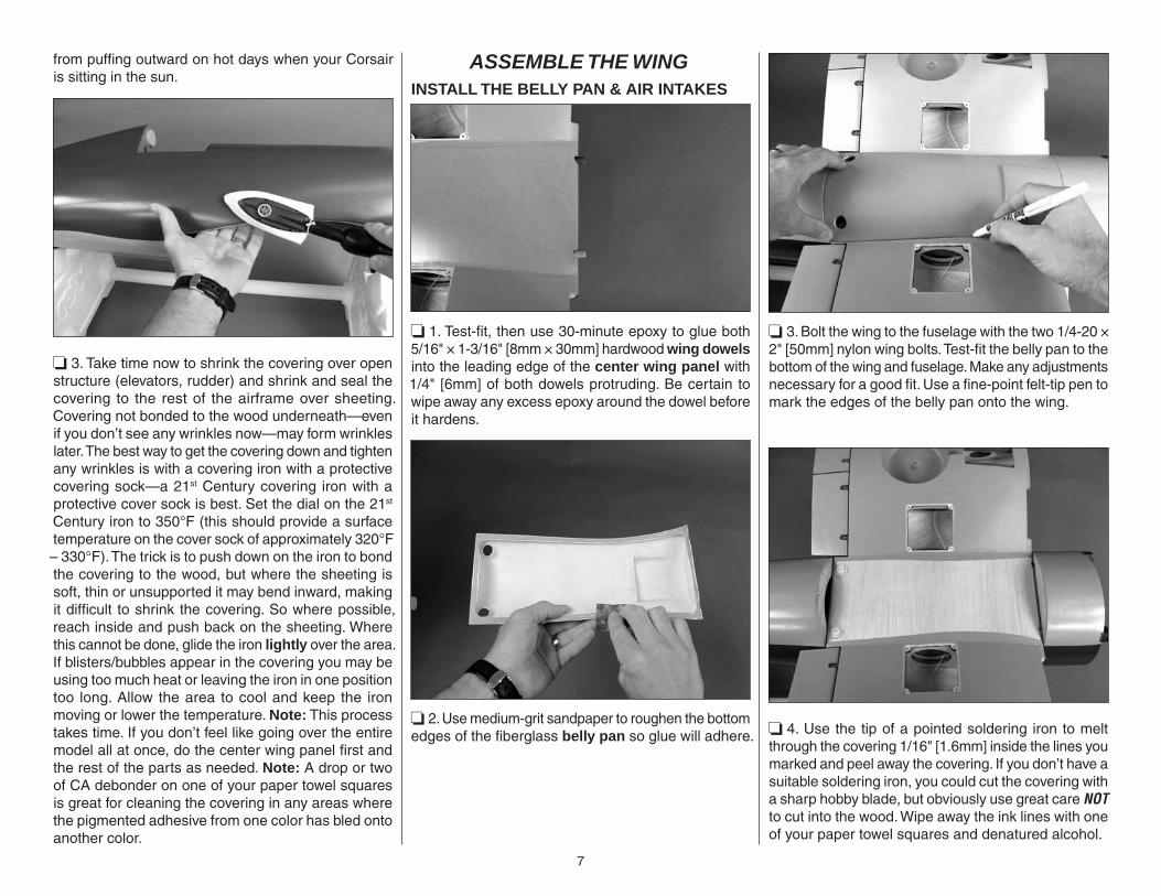
❏ 3. Take time now to shrink the covering over open structure (elevators, rudder) and shrink and seal the covering to the rest of the airframe over sheeting. Covering not bonded to the wood underneath—even if you don’t see any wrinkles now—may form wrinkles later. The best way to get the covering down and tighten any wrinkles is with a covering iron with a protective covering sock—a 21st Century covering iron with a protective cover sock is best. Set the dial on the 21st Century iron to 350°F (this should provide a surface temperature on the cover sock of approximately 320°F – 330°F). The trick is to push down on the iron to bond the covering to the wood, but where the sheeting is soft, thin or unsupported it may bend inward, making it diffi cult to shrink the covering. So where possible, reach inside and push back on the sheeting. Where this cannot be done, glide the iron lightly over the area. If blisters/bubbles appear in the covering you may be using too much heat or leaving the iron in one position too long. Allow the area to cool and keep the iron moving or lower the temperature. Note: This process takes time. If you don’t feel like going over the entire model all at once, do the center wing panel fi rst and the rest of the parts as needed. Note: A drop or two of CA debonder on one of your paper towel squares is great for cleaning the covering in any areas where the pigmented adhesive from one color has bled onto another color.
ASSEMBLE THE WING INSTALL THE BELLY PAN & AIR INTAKES
❏ 1. Test-fi t, then use 30-minute epoxy to glue both 5/16" × 1-3/16" [8mm × 30mm] hardwood wing dowels into the leading edge of the center wing panel with 1/4" [6mm] of both dowels protruding. Be certain to wipe away any excess epoxy around the dowel before it hardens.
❏ 2. Use medium-grit sandpaper to roughen the bottom edges of the fi berglass belly pan so glue will adhere.
❏ 3. Bolt the wing to the fuselage with the two 1/4-20 × 2" [50mm] nylon wing bolts. Test-fi t the belly pan to the bottom of the wing and fuselage. Make any adjustments necessary for a good fi t. Use a fi ne-point felt-tip pen to mark the edges of the belly pan onto the wing.
❏ 4. Use the tip of a pointed soldering iron to melt through the covering 1/16" [1.6mm] inside the lines you marked and peel away the covering. If you don’t have a suitable soldering iron, you could cut the covering with a sharp hobby blade, but obviously use great care NOT to cut into the wood. Wipe away the ink lines with one of your paper towel squares and denatured alcohol.

8
❏ 5. Glue the belly pan into position with 30-minute epoxy—use care not to allow excess epoxy to inadvertently glue the wing or belly pan to the fuselage.
❏ 6. With the wing mounted to the fuselage, hold the left wing air intake up against the fuselage. Use a fi ne-point felt-tip pen to mark where to trim the intake for a perfect fi t.
❏ 7. Trim and fi t the intake as necessary until it fi ts well.
❏ 8. Holding the intake in position, use a fi ne-point felt-tip pen to mark its outline onto the top and bottom of the wing.
❏ 9. Use a small pin to perforate the covering just inside the outlines.
❏ 10. Use one of your paper towel squares and denatured alcohol to wipe the ink lines from the wing. Hold the intake into position and carefully glue it to the wing with thin CA. Or, use J&Z R/C 56 canopy glue instead. If using canopy glue, hold the intake to the wing with masking tape until the glue dries. Hint: If using CA, fi rst use CA accelerator to lightly “prime” the underside of the intake where it contacts the wing. Allow the accelerator to dry for a few seconds, then glue in place.
❏ 11. Trim, fi t and glue the right intake into position the same way.

9
HOOK UP THE FLAPS AND AILERONS
Center Panel
Outer Panels
Before hooking up the fl aps and ailerons note the orientation of the servo hatch covers in the bottom of the wing panels.
❏ 1. Install the rubber grommets and eyelets into the servos. Hold two hardwood servo mount blocks to your fl ap servo with thin cardstock or 1/32" [.8mm] plywood spacers under the servo and between the blocks and the servo to provide the necessary spacing for proper vibration isolation. Drill 1/16" [1.6mm] holes into the servo mount blocks for the servo mounting screws and mount the servo to the blocks with the screws that came with the servos.
❏ 2. Mount the other fl ap servo to another set of mount blocks the same way.
❏ 3. Temporarily place the servo arms on the fl ap servos to aid in centering them in the hatch openings. Use 30-minute epoxy to securely glue the mount blocks to the hatch covers with the arms centered both fore and aft and side-to-side in the openings—be certain to apply epoxy to the ends of the blocks and to the hatch for a secure bond.
❏ 4. Cut two 6" [150mm] pushrods to a length of 4-1/4" [108mm] by cutting the un-threaded end. Read the Expert Tip that follows about soldering, then solder a clevis onto one end of each pushrod. While you have your soldering equipment out, go ahead and cut the aileron pushrods to a length of 3-1/4" [83mm] and solder the clevises to them as well.
HOW TO SOLDER
1. Use denatured alcohol or other solvent to thoroughly clean the pushrod. Roughen the end of the pushrod with coarse sandpaper where it is to be soldered.
2. Apply a few drops of soldering fl ux to the end of the pushrod, and then use a soldering iron or a torch to heat it. “Tin” the heated area with silver solder by applying the solder to the end. The heat of the pushrod should melt the solder – not the fl ame of the torch or soldering iron – thus allowing the solder to fl ow. The end of the wire should be coated with solder all the way around.
3. Place the clevis on the end of the pushrod. Add another drop of fl ux, then heat and add solder. The same as before, the heat of the parts being soldered should melt the solder, thus allowing it to fl ow. Allow the joint to cool naturally without being disturbed. Avoid excess blobs, but make certain the joint is thoroughly soldered. The solder should be shiny, not rough. If necessary, reheat the joint and allow to cool.
4. Immediately after the solder has solidifi ed, but while it is still hot, use a cloth to quickly wipe off the fl ux before it hardens. Important: After the joint cools, coat the joint with oil to prevent rust. Note: Do not use the acid fl ux that comes with silver solder for electrical soldering.
This is what a properly soldered clevis looks like – shiny solder with good flow, no blobs and flux removed.
Aile
ron
Push
rod
3-1
/4"
[83
mm
]
4-1/
4" [
108
mm
]
FlapPushrod
10
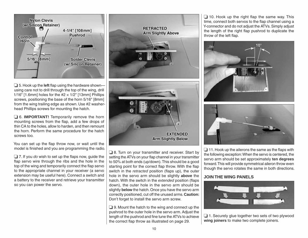
❏ 5. Hook up the left fl ap using the hardware shown—using care not to drill through the top of the wing, drill 1/16" [1.6mm] holes for the #2 × 1/2" [13mm] Phillips screws, positioning the base of the horn 5/16" [8mm] from the wing trailing edge as shown. Use #2 washer-head Phillips screws for mounting the hatch.
❏ 6. IMPORTANT! Temporarily remove the horn mounting screws from the fl ap, add a few drops of thin CA to the holes, allow to harden, and then remount the horn. Perform the same procedure for the hatch screws too.
You can set up the fl ap throw now, or wait until the model is fi nished and you are programming the radio.
❏ 7. If you do wish to set up the fl aps now, guide the fl ap servo wire through the ribs and the hole in the top of the wing and temporarily connect the fl ap servo to the appropriate channel in your receiver (a servo extension may be useful here). Connect a switch and a battery to the receiver and retrieve your transmitter so you can power the servo.
❏ 8. Turn on your transmitter and receiver. Start by setting the ATVs on your fl ap channel in your transmitter to 50% at both ends (up/down). This should be a good starting point for the correct fl ap throw. With the fl ap switch in the retracted position (fl aps up), the outer hole in the servo arm should be slightly above the hatch. With the switch in the extended position (fl aps down), the outer hole in the servo arm should be slightly below the hatch. Once you have the servo arm correctly positioned, cut off the unused arms. Caution: Don’t forget to install the servo arm screw.
❏ 9. Mount the hatch to the wing and connect up the pushrod to the outer hole in the servo arm. Adjust the length of the pushrod and fi ne tune the ATVs to achieve the correct fl ap throw as illustrated on page 29.
❏ 10. Hook up the right fl ap the same way. This time, connect both servos to the fl ap channel using a Y-connector and do not adjust the ATVs. Simply adjust the length of the right fl ap pushrod to duplicate the throw of the left fl ap.
❏ 11. Hook up the ailerons the same as the fl aps with the following exception: When the servo is centered, the servo arm should be set approximately ten degrees forward. This will provide symmetrical aileron throw even though the servo rotates the same in both directions.
JOIN THE WING PANELS
❏ 1. Securely glue together two sets of two plywood wing joiners to make two complete joiners.

11
❏ 2. Glue the 1/8" [3.2mm] plastic alignment pins halfway into both ends of the center panel.
❏ 3. Test fi t, but do not glue one, then the other outer panel to the inner panel with the wing joiners. Make any adjustments necessary for a good fi t.
❏ 4. Install two 24" [610mm] servo extension wires through one side, then the other side of the center panel that will connect to the aileron servo wires when the wings are permanently joined (it will be helpful to temporarily remove the fl ap servo hatches to help guide the wires).
❏ 5. Cut one of the included pieces of shrink tubing in half. Use the tubing to connect the aileron servo wire coming out of one of the panels to the servo extension wire coming from the respective end of the center panel. Carefully shrink the tubing with a hobby torch or a heat gun.
❏ 6. Gather everything required to glue together the panels: 30-minute epoxy, mixing sticks and cups, epoxy brushes, masking tape and your paper towel squares and denatured alcohol for epoxy clean up.
Note: Join only one outer panel to the center panel at a time with one batch of epoxy—do not attempt to join both outer panels at the same time or with the same batch. Otherwise, you may run out of working time before the epoxy begins to harden.
❏ 7. Mix approximately 3/4 oz. of 30-minute epoxy. Liberally apply epoxy in the spar “pocket” in the outer wing panel and all the way around the outer half of one of the joiners. Insert the joiner into the outer panel, and then coat the pocket in the inner panel and all other joining surfaces with epoxy. Proceeding quickly, join the panels and proceed to the next step. IMPORTANT: Don’t forget to key the tab in the outer fl ap into the slot in the middle fl ap.
❏ 8. Use paper towel squares dampened with denatured alcohol to wipe away epoxy as it squeezes
from the wing when you press the panels together. Use several strips of masking tape to tightly tape the panels together. As the epoxy hardens and continues to leak from the seam, one strip at a time, remove the tape, wipe away the epoxy, and then immediately replace it with another strip to keep the wing tightly clamped. Continue to monitor the wing, wiping away leaking epoxy and making sure the gap remains tight.
❏ 9. After the epoxy has hardened, carefully remove all the tape. If the epoxy is hard but has not yet fully cured, there is still time to clean up any remaining epoxy with paper towel squares dampened with denatured alcohol.
❏ 10. Join the other panel the same way – don’t forget fi rst to connect the other aileron servo wire to the other extension in the wing and secure the connection with heat shrink tubing. After all the epoxy has been cleaned up, use a covering iron to re bond any covering that may have pulled away when removing the tape.
INSTALL THE RETRACTABLE LANDING GEAR
If not mounting retractable landing gear, skip to “Mount the Fixed Landing Gear ” on page 14.
❏ 1. Note: There are no fl at spots on the ends of the struts for the set screws in the toothed cam gear. It is highly recommended that you remove the struts and grind at least one fl at spot for one of the set screws in the collar. Otherwise, the strut may slip in the collar on the gear. When reattaching the gear to the strut, threadlocker should also be used on the threads of the set screws.
12
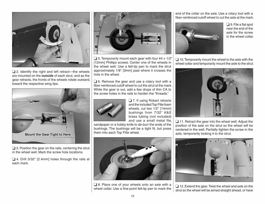
❏ 2. Identify the right and left retract—the wheels are mounted on the outside of each strut, and as the gear retracts, the fronts of the wheels rotate outward, toward the respective wing tips.
❏ 3. Position the gear on the rails, centering the strut in the wheel well. Mark the screw hole locations.
❏ 4. Drill 3/32" [2.4mm] holes through the rails at each mark.
❏ 5. Temporarily mount each gear with four #4 × 1/2" [12mm] Phillips screws. Center one of the wheels in the wheel well. Use a felt-tip pen to mark the strut approximately 1/8" [3mm] past where it crosses the hole in the wheel.
❏ 6. Remove the gear and use a rotary tool with a fi ber-reinforced cutoff wheel to cut the strut at the mark. While the gear is out, add a few drops of thin CA to the screw holes in the rails to harden the “threads.”
❏ 7. If using Robart retracts and the included Top Flite foam wheels, cut two 1/2" [14mm] bushings from 7/32" K&S brass tubing (not included) and use a small metal fi le,
sandpaper or a hobby knife to de-burr the ends of the bushings. The bushings will be a tight fi t, but press them into each Top Flite wheel.
❏ 8. Place one of your wheels onto an axle with a wheel collar. Use a fi ne-point felt-tip pen to mark the
end of the collar on the axle. Use a rotary tool with a fi ber-reinforced cutoff wheel to cut the axle at the mark.
❏ 9. File a fl at spot near the end of the axle for the screw in the wheel collar.
❏ 10. Temporarily mount the wheel to the axle with the wheel collar and temporarily mount the axle to the strut.
❏ 11. Retract the gear into the wheel well. Adjust the position of the axle on the strut so the wheel will be centered in the well. Partially tighten the screw in the axle, temporarily locking it to the strut.
❏ 12. Extend the gear. Twist the wheel and axle on the strut so the wheel will be aimed straight ahead, or have
13
approximately 1 degree of toe-in. Securely tighten the screw in the axle onto the strut, then partially loosen and tighten again so the screw will mark the location where it has bottomed out on the strut. This will identify the precise location where a fl at spot is to be ground into the strut.
❏ 13. Remove the axle from the strut and remove the retract from the wing. Grind a fl at spot into the strut at the mark left by the screw in the previous step.
❏ 14. Tighten the axle onto the strut. Mount the gear to the rail. View the wheel to see if the alignment is correct. If necessary, adjust the fl at spot until the wheel is straight ahead, or has a small amount of toe-in.
❏ 15. Once the wheel and axle are properly aligned, add a drop of threadlocker to the threads on the axle screw, then securely tighten the screw in the axle locking the axle to the strut. Also use a small drop of threadlocker on the screw that secures the collar mounting the wheel to the axle.
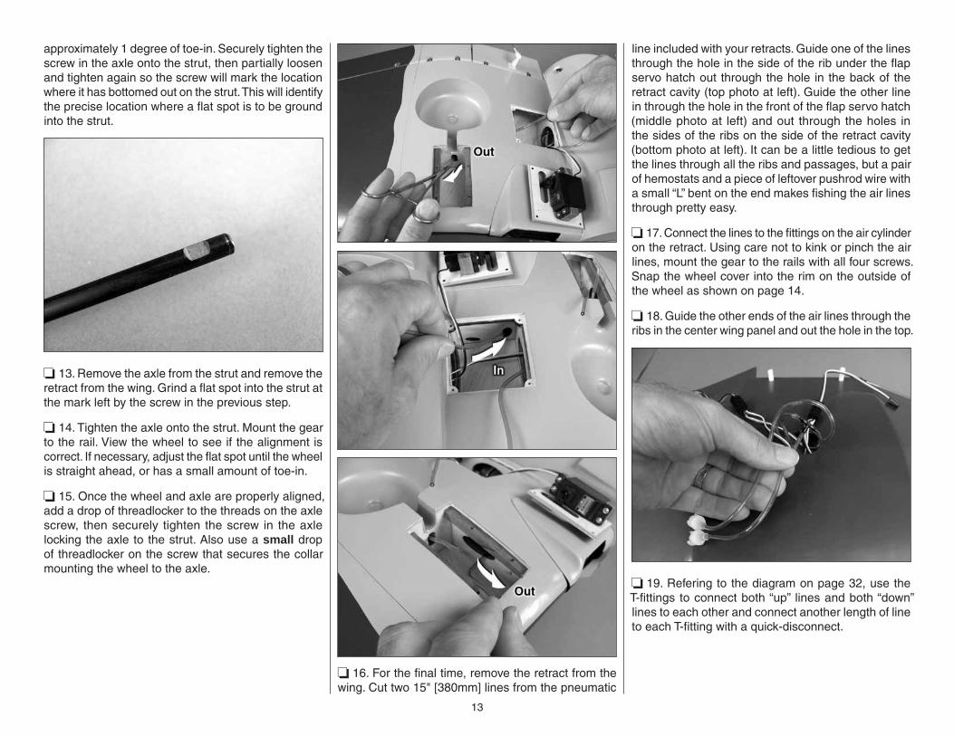
❏ 16. For the fi nal time, remove the retract from the wing. Cut two 15" [380mm] lines from the pneumatic
line included with your retracts. Guide one of the lines through the hole in the side of the rib under the fl ap servo hatch out through the hole in the back of the retract cavity (top photo at left). Guide the other line in through the hole in the front of the fl ap servo hatch (middle photo at left) and out through the holes in the sides of the ribs on the side of the retract cavity (bottom photo at left). It can be a little tedious to get the lines through all the ribs and passages, but a pair of hemostats and a piece of leftover pushrod wire with a small “L” bent on the end makes fi shing the air lines through pretty easy.
❏ 17. Connect the lines to the fi ttings on the air cylinder on the retract. Using care not to kink or pinch the air lines, mount the gear to the rails with all four screws. Snap the wheel cover into the rim on the outside of the wheel as shown on page 14.
❏ 18. Guide the other ends of the air lines through the ribs in the center wing panel and out the hole in the top.
❏ 19. Refering to the diagram on page 32, use the T-fi ttings to connect both “up” lines and both “down” lines to each other and connect another length of line to each T-fi tting with a quick-disconnect.
14
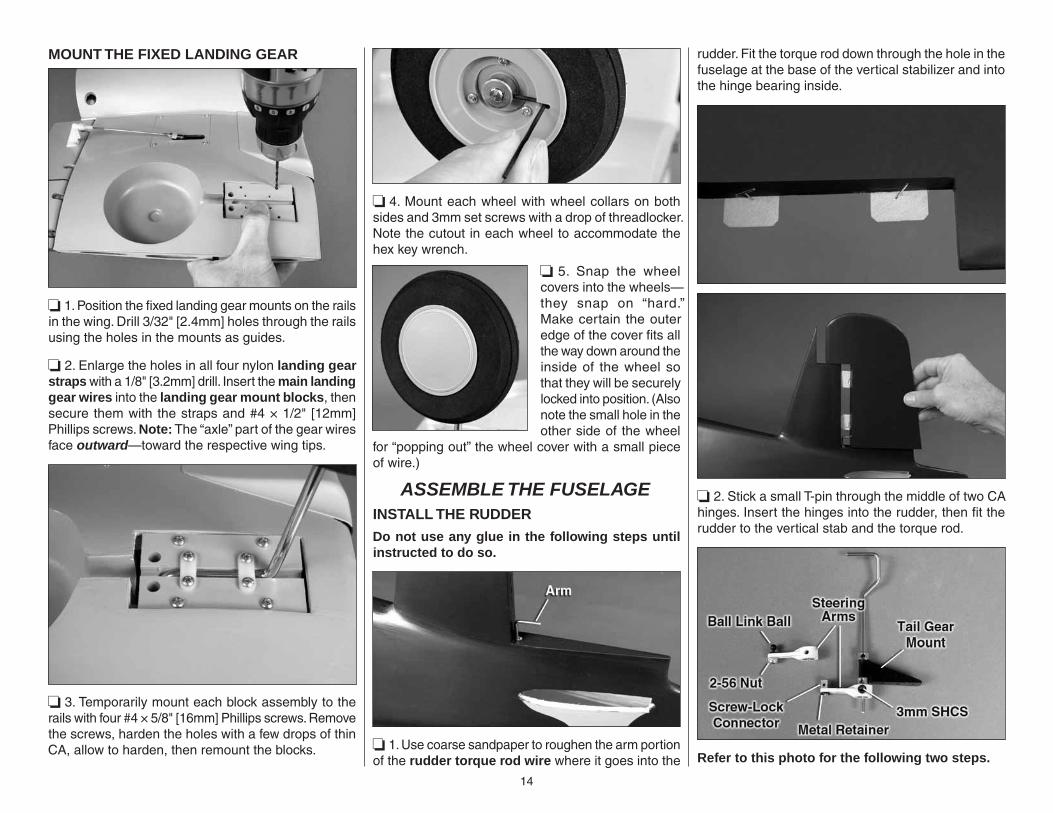
MOUNT THE FIXED LANDING GEAR
❏ 1. Position the fi xed landing gear mounts on the rails in the wing. Drill 3/32" [2.4mm] holes through the rails using the holes in the mounts as guides.
❏ 2. Enlarge the holes in all four nylon landing gear straps with a 1/8" [3.2mm] drill. Insert the main landing gear wires into the landing gear mount blocks, then secure them with the straps and #4 × 1/2" [12mm] Phillips screws. Note: The “axle” part of the gear wires face outward—toward the respective wing tips.
❏ 3. Temporarily mount each block assembly to the rails with four #4 × 5/8" [16mm] Phillips screws. Remove the screws, harden the holes with a few drops of thin CA, allow to harden, then remount the blocks.
❏ 4. Mount each wheel with wheel collars on both sides and 3mm set screws with a drop of threadlocker. Note the cutout in each wheel to accommodate the hex key wrench.
❏ 5. Snap the wheel covers into the wheels—they snap on “hard.” Make certain the outer edge of the cover fi ts all the way down around the inside of the wheel so that they will be securely locked into position. (Also note the small hole in the other side of the wheel
for “popping out” the wheel cover with a small piece of wire.)
ASSEMBLE THE FUSELAGEINSTALL THE RUDDER
Do not use any glue in the following steps until instructed to do so.
❏ 1. Use coarse sandpaper to roughen the arm portion of the rudder torque rod wire where it goes into the
rudder. Fit the torque rod down through the hole in the fuselage at the base of the vertical stabilizer and into the hinge bearing inside.
❏ 2. Stick a small T-pin through the middle of two CA hinges. Insert the hinges into the rudder, then fi t the rudder to the vertical stab and the torque rod.
Refer to this photo for the following two steps.
15
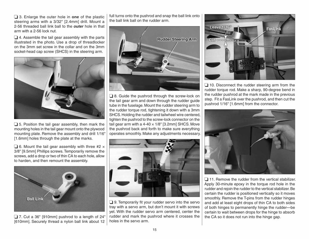
❏ 3. Enlarge the outer hole in one of the plastic steering arms with a 3/32" [2.4mm] drill. Mount a 2-56 threaded ball link ball to the outer hole in that arm with a 2-56 lock nut.
❏ 4. Assemble the tail gear assembly with the parts illustrated in the photo. Use a drop of threadlocker on the 3mm set screw in the collar and on the 3mm socket-head cap screw (SHCS) in the steering arm.
❏ 5. Position the tail gear assembly, then mark the mounting holes in the tail gear mount onto the plywood mounting plate. Remove the assembly and drill 1/16" [1.6mm] holes through the plate at the marks.
❏ 6. Mount the tail gear assembly with three #2 × 3/8" [9.5mm] Phillips screws. Temporarily remove the screws, add a drop or two of thin CA to each hole, allow to harden, and then remount the assembly.
❏ 7. Cut a 36" [910mm] pushrod to a length of 24" [610mm]. Securely thread a nylon ball link about 12
full turns onto the pushrod and snap the ball link onto the ball link ball on the rudder arm.
❏ 8. Guide the pushrod through the screw-lock on the tail gear arm and down through the rudder guide tube in the fuselage. Mount the rudder steering arm to the rudder torque rod, tightening it down with a 3mm SHCS. Holding the rudder and tailwheel wire centered, tighten the pushrod to the screw-lock connector on the tail gear arm with a 4-40 × 1/8" [3.2mm] SHCS. Move the pushrod back and forth to make sure everything operates smoothly. Make any adjustments necessary.
❏ 9. Temporarily fi t your rudder servo into the servo tray with a servo arm, but don’t mount it with screws yet. With the rudder servo arm centered, center the rudder and mark the pushrod where it crosses the holes in the servo arm.
❏ 10. Disconnect the rudder steering arm from the rudder torque rod. Make a sharp, 90-degree bend in the rudder pushrod at the mark made in the previous step. Fit a FasLink over the pushrod, and then cut the pushrod 1/16" [1.6mm] from the connector.
❏ 11. Remove the rudder from the vertical stabilizer. Apply 30-minute epoxy in the torque rod hole in the rudder and rejoin the rudder to the vertical stabilizer. Be certain the rudder is positioned vertically so it moves smoothly. Remove the T-pins from the rudder hinges and add at least eight drops of thin CA to both sides of both hinges to permanently hinge the rudder—be certain to wait between drops for the hinge to absorb the CA so it does not run into the hinge gap.
16
❏ 12. For the fi nal time, securely connect the rudder steering arm to the rudder torque rod using a drop of threadlocker on the 3mm SHCS.
❏ 13. If necessary, rotate the rudder pushrod so the “L” bend in the front of the pushrod is vertical and will fi t correctly into the rudder servo arm. Enlarge the holes in the servo arm with a #47 (.076" [1.9mm]) drill, then mount the pushrod to the outer hole. On the back end, center the axle on the tail gear, and lock the pushrod to the connector by tightening the 4-40 screw with a drop of threadlocker on the threads.
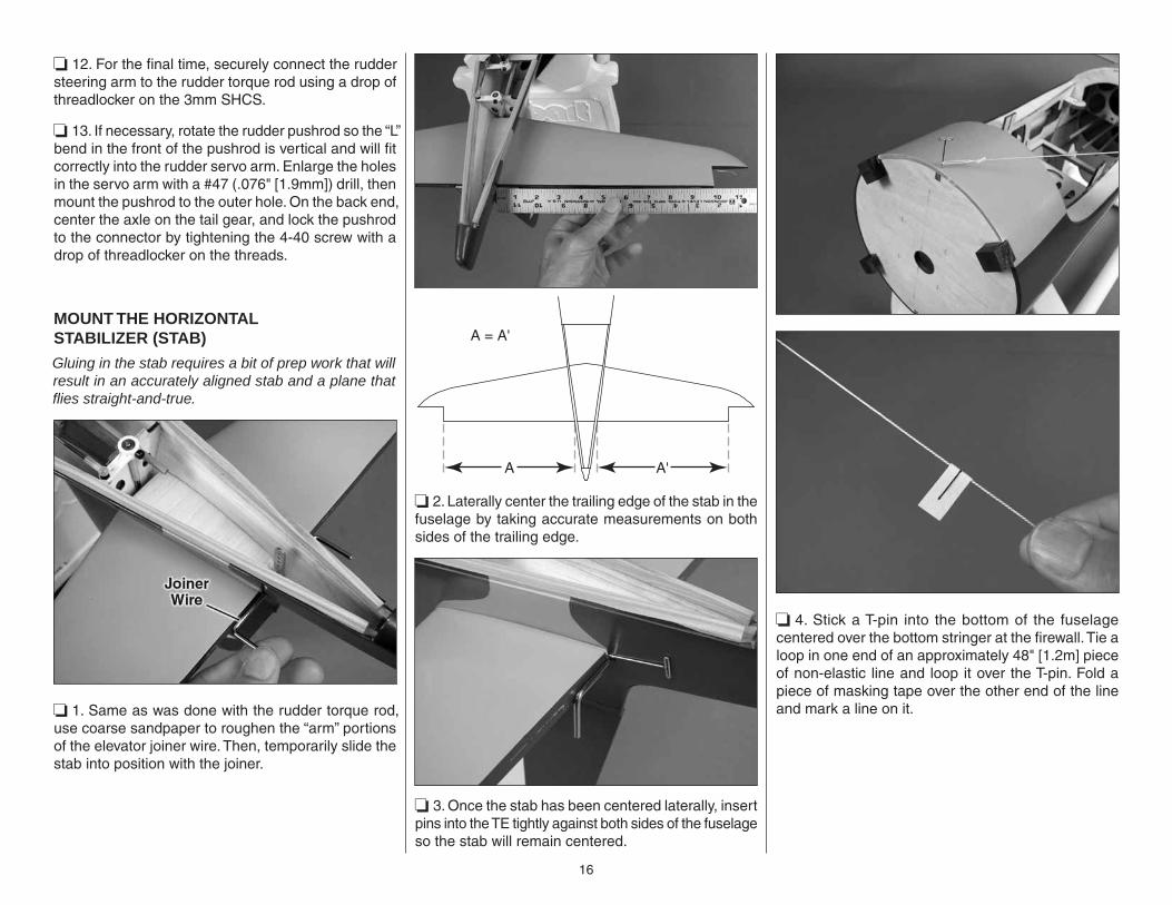
MOUNT THE HORIZONTALSTABILIZER (STAB)
Gluing in the stab requires a bit of prep work that will result in an accurately aligned stab and a plane that fl ies straight-and-true.
❏ 1. Same as was done with the rudder torque rod, use coarse sandpaper to roughen the “arm” portions of the elevator joiner wire. Then, temporarily slide the stab into position with the joiner.
A
A = A'
A'
❏ 2. Laterally center the trailing edge of the stab in the fuselage by taking accurate measurements on both sides of the trailing edge.
❏ 3. Once the stab has been centered laterally, insert pins into the TE tightly against both sides of the fuselage so the stab will remain centered.
❏ 4. Stick a T-pin into the bottom of the fuselage centered over the bottom stringer at the fi rewall. Tie a loop in one end of an approximately 48" [1.2m] piece of non-elastic line and loop it over the T-pin. Fold a piece of masking tape over the other end of the line and mark a line on it.
17
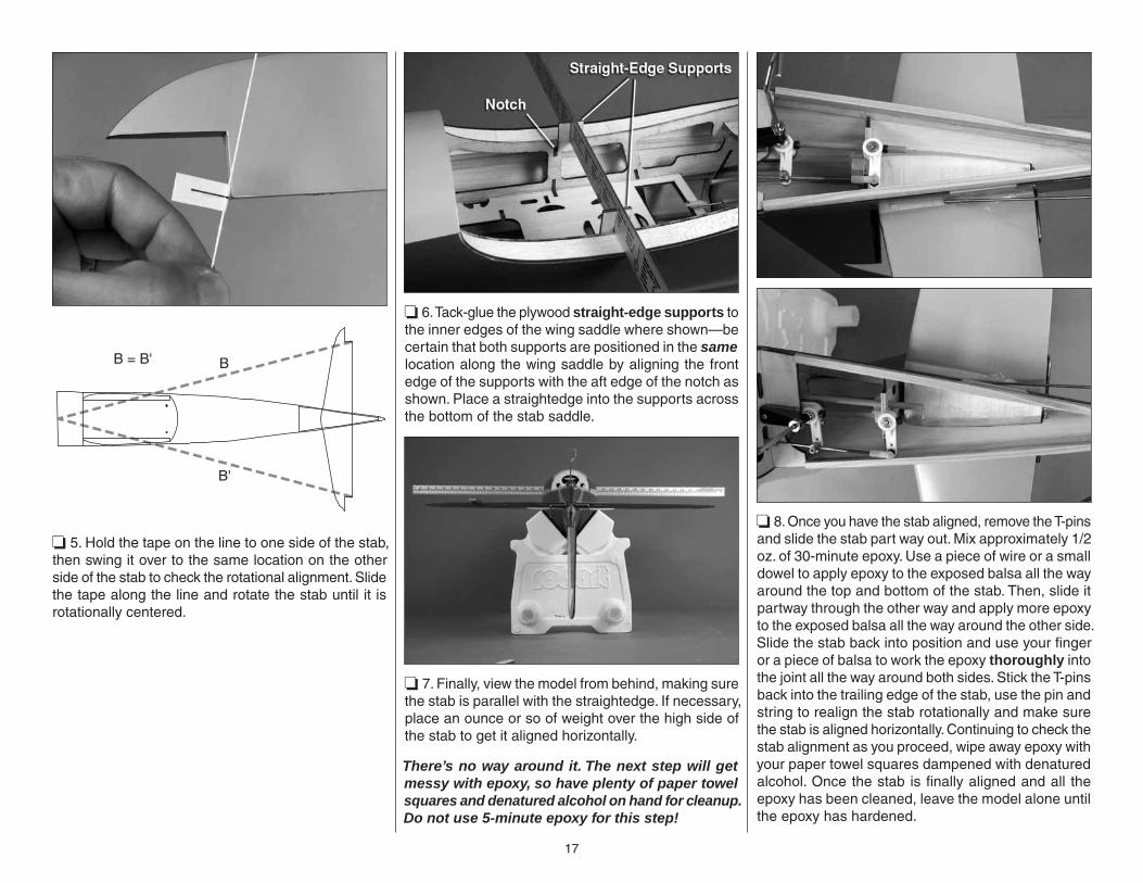
B = B' B
B'
❏ 5. Hold the tape on the line to one side of the stab, then swing it over to the same location on the other side of the stab to check the rotational alignment. Slide the tape along the line and rotate the stab until it is rotationally centered.
❏ 6. Tack-glue the plywood straight-edge supports to the inner edges of the wing saddle where shown—be certain that both supports are positioned in the same location along the wing saddle by aligning the front edge of the supports with the aft edge of the notch as shown. Place a straightedge into the supports across the bottom of the stab saddle.
❏ 7. Finally, view the model from behind, making sure the stab is parallel with the straightedge. If necessary, place an ounce or so of weight over the high side of the stab to get it aligned horizontally.
There’s no way around it. The next step will get messy with epoxy, so have plenty of paper towel squares and denatured alcohol on hand for cleanup. Do not use 5-minute epoxy for this step!
❏ 8. Once you have the stab aligned, remove the T-pins and slide the stab part way out. Mix approximately 1/2 oz. of 30-minute epoxy. Use a piece of wire or a small dowel to apply epoxy to the exposed balsa all the way around the top and bottom of the stab. Then, slide it partway through the other way and apply more epoxy to the exposed balsa all the way around the other side. Slide the stab back into position and use your fi nger or a piece of balsa to work the epoxy thoroughly into the joint all the way around both sides. Stick the T-pins back into the trailing edge of the stab, use the pin and string to realign the stab rotationally and make sure the stab is aligned horizontally. Continuing to check the stab alignment as you proceed, wipe away epoxy with your paper towel squares dampened with denatured alcohol. Once the stab is fi nally aligned and all the epoxy has been cleaned, leave the model alone until the epoxy has hardened.

18
❏ 9. Same as after the wing panels were joined, if you can catch the epoxy after it has hardened but before it has fully cured, you may still be able to clean off any remaining epoxy with more paper towel squares and denatured alcohol.
INSTALL THE ELEVATORS
❏ 1. Same as the rudder, insert a T-pin through the middle of six CA hinges, then test fi t the elevators to the stab and the joiner wire. View the elevators from the rear and make certain they align with each other. If necessary, remove the elevators and use two pair of pliers to bend the torque rod arms so the elevators will align.
❏ 2. Move the elevators up and down to make sure you are getting the full, high-rate elevator throw specifi ed on page 29. If the root end of one of the elevators interferes with the fuselage side, the elevators may not be centered laterally. Shift the elevators with the joiner rod to one side or the other to get them centered.
❏ 3. Once you understand how to align the elevators, remove them from the stab, add 30-minute epoxy into the holes for the joiner wire, rejoin the elevators to the stab, and remove the T-pins from the hinges. Permanently join the elevators by applying thin CA to the hinges.
❏ 4. After the epoxy on the joiner wire has hardened, cut a 36" [910mm] pushrod to a length of 30" [760mm]. Thread a nylon clevis onto the pushrod approximately twenty full turns. Same as was done for the rudder pushrod, bend and cut the pushrod to the correct length to fi t the elevator servo with a 90-degree pushrod connector. Connect the clevis to the bottom hole (farthest from the elevator) in the control horn with a silicone retainer around the clevis.
INSTALL THE TAIL GEAR COVER
❏ 1. Glue both hardwood blocks into position on the tail gear mount plate where shown—with the front of the blocks approximately 1/4" [6mm] back from the former.
❏ 2. Holding the fi berglass cover in position, use a pencil to mark the center of the block onto the cover, then mark four more lines every 2-3/8" [60mm] behind the fi rst. Repeat the procedure for the other side of the cover.
19
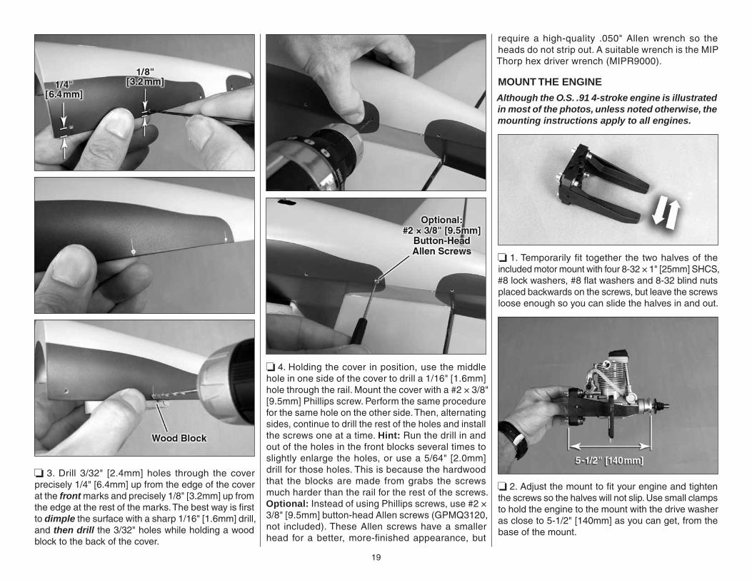
❏ 3. Drill 3/32" [2.4mm] holes through the cover precisely 1/4" [6.4mm] up from the edge of the cover at the front marks and precisely 1/8" [3.2mm] up from the edge at the rest of the marks. The best way is fi rst to dimple the surface with a sharp 1/16" [1.6mm] drill, and then drill the 3/32" holes while holding a wood block to the back of the cover.
❏ 4. Holding the cover in position, use the middle hole in one side of the cover to drill a 1/16" [1.6mm] hole through the rail. Mount the cover with a #2 × 3/8" [9.5mm] Phillips screw. Perform the same procedure for the same hole on the other side. Then, alternating sides, continue to drill the rest of the holes and install the screws one at a time. Hint: Run the drill in and out of the holes in the front blocks several times to slightly enlarge the holes, or use a 5/64" [2.0mm] drill for those holes. This is because the hardwood that the blocks are made from grabs the screws much harder than the rail for the rest of the screws. Optional: Instead of using Phillips screws, use #2 × 3/8" [9.5mm] button-head Allen screws (GPMQ3120, not included). These Allen screws have a smaller head for a better, more-fi nished appearance, but
require a high-quality .050" Allen wrench so the heads do not strip out. A suitable wrench is the MIP Thorp hex driver wrench (MIPR9000).
MOUNT THE ENGINE
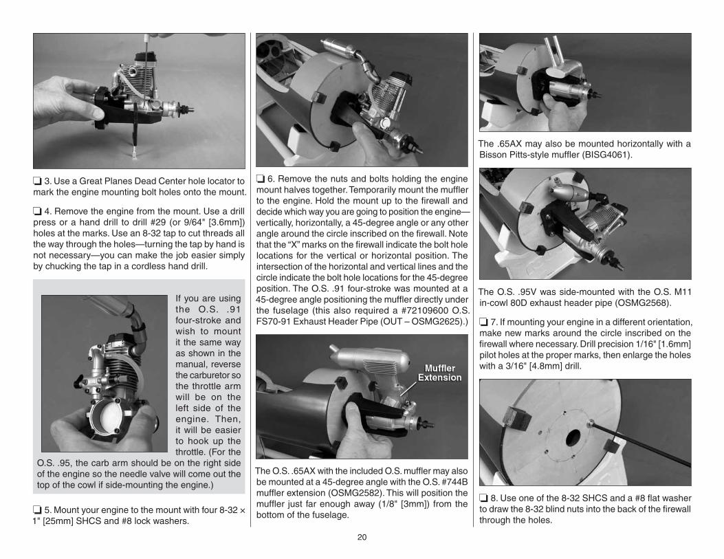
Although the O.S. .91 4-stroke engine is illustrated in most of the photos, unless noted otherwise, the mounting instructions apply to all engines.
❏ 1. Temporarily fi t together the two halves of the included motor mount with four 8-32 × 1" [25mm] SHCS, #8 lock washers, #8 fl at washers and 8-32 blind nuts placed backwards on the screws, but leave the screws loose enough so you can slide the halves in and out.
❏ 2. Adjust the mount to fi t your engine and tighten the screws so the halves will not slip. Use small clamps to hold the engine to the mount with the drive washer as close to 5-1/2" [140mm] as you can get, from the base of the mount.
20
❏ 3. Use a Great Planes Dead Center hole locator to mark the engine mounting bolt holes onto the mount.
❏ 4. Remove the engine from the mount. Use a drill press or a hand drill to drill #29 (or 9/64" [3.6mm]) holes at the marks. Use an 8-32 tap to cut threads all the way through the holes—turning the tap by hand is not necessary—you can make the job easier simply by chucking the tap in a cordless hand drill.
If you are using the O.S. .91 four-stroke and wish to mount it the same way as shown in the manual, reverse the carburetor so the throttle arm will be on the left side of the engine. Then, it will be easier to hook up the throttle. (For the
O.S. .95, the carb arm should be on the right side of the engine so the needle valve will come out the top of the cowl if side-mounting the engine.)
❏ 5. Mount your engine to the mount with four 8-32 × 1" [25mm] SHCS and #8 lock washers.
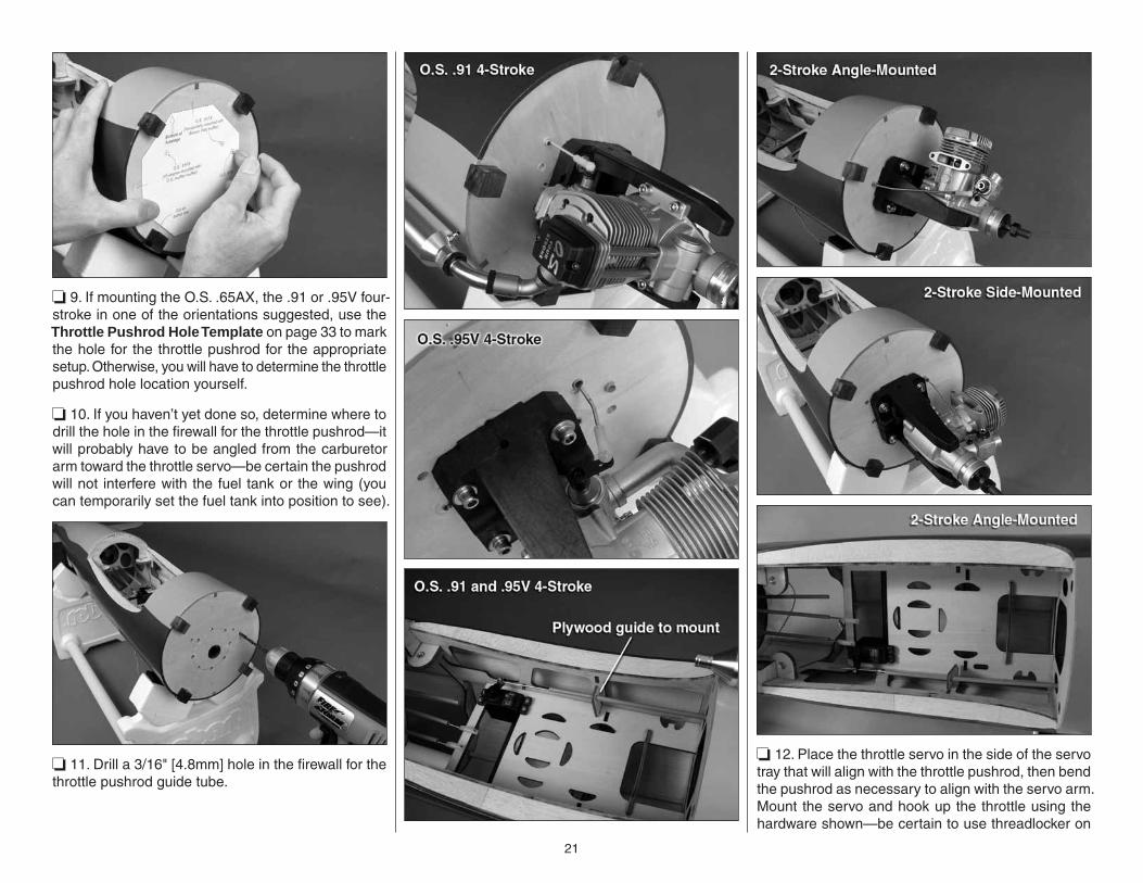
❏ 6. Remove the nuts and bolts holding the engine mount halves together. Temporarily mount the muffl er to the engine. Hold the mount up to the fi rewall and decide which way you are going to position the engine—vertically, horizontally, a 45-degree angle or any other angle around the circle inscribed on the fi rewall. Note that the “X” marks on the fi rewall indicate the bolt hole locations for the vertical or horizontal position. The intersection of the horizontal and vertical lines and the circle indicate the bolt hole locations for the 45-degree position. The O.S. .91 four-stroke was mounted at a 45-degree angle positioning the muffl er directly under the fuselage (this also required a #72109600 O.S. FS70-91 Exhaust Header Pipe (OUT – OSMG2625).)
The O.S. .65AX with the included O.S. muffl er may also be mounted at a 45-degree angle with the O.S. #744B muffl er extension (OSMG2582). This will position the muffl er just far enough away (1/8" [3mm]) from the bottom of the fuselage.
The .65AX may also be mounted horizontally with a Bisson Pitts-style muffl er (BISG4061).
The O.S. .95V was side-mounted with the O.S. M11 in-cowl 80D exhaust header pipe (OSMG2568).
❏ 7. If mounting your engine in a different orientation, make new marks around the circle inscribed on the fi rewall where necessary. Drill precision 1/16" [1.6mm] pilot holes at the proper marks, then enlarge the holes with a 3/16" [4.8mm] drill.
❏ 8. Use one of the 8-32 SHCS and a #8 fl at washer to draw the 8-32 blind nuts into the back of the fi rewall through the holes.
21
❏ 9. If mounting the O.S. .65AX, the .91 or .95V four-stroke in one of the orientations suggested, use the Throttle Pushrod Hole Template on page 33 to mark the hole for the throttle pushrod for the appropriate setup. Otherwise, you will have to determine the throttle pushrod hole location yourself.
❏ 10. If you haven’t yet done so, determine where to drill the hole in the fi rewall for the throttle pushrod—it will probably have to be angled from the carburetor arm toward the throttle servo—be certain the pushrod will not interfere with the fuel tank or the wing (you can temporarily set the fuel tank into position to see).
❏ 11. Drill a 3/16" [4.8mm] hole in the fi rewall for the throttle pushrod guide tube.
❏ 12. Place the throttle servo in the side of the servo tray that will align with the throttle pushrod, then bend the pushrod as necessary to align with the servo arm. Mount the servo and hook up the throttle using the hardware shown—be certain to use threadlocker on
22
the threaded ball link ball on the carburetor arm. Glue in one of the plywood guide tube mounts where necessary to stabilize the throttle guide tube.
INSTALL THE FUEL TANK
❏ 1. Cut one of the longer aluminum fuel tubes in half by rolling it back-and-forth several times under a hobby blade. Insert both
halves of the tube, and the other longer tube through the rubber stopper (it helps to wet the holes in the stopper with saliva).
❏ 2. Assemble the rest of the stopper assembly as shown—be certain the clunks on the ends of the fuel lines will not contact the back of the tank. Otherwise, they could become stuck, causing an interruption in fuel fl ow. Bend the vent tube upward so it will be at the top of the tank when the stopper is inserted.
FuselageTop
❏ 3. Fit the stopper assembly into the tank and tighten the screw to expand the stopper and seal the tank. Make certain the stopper is secure and make sure the clunks on the ends of the fuel lines are not contacting the back of the tank.
❏ 4. Fit the tank into position and hold it in place with one or two #64 rubber bands.
We’ll install and connect the fuel lines later.
MOUNT THE COWL
On models where the engine and/or muffl er protrude from the cowl, cutting holes for the engine and muffl er can be a “catch-22.” You can’t know precisely where to cut holes until the cowl is mounted, but you can’t mount the cowl over the engine until the holes are cut. Sometimes templates work, but templates cannot be made for every engine/muffl er combination. Usually, the best way is to carefully and gradually cut and fi t as illustrated:
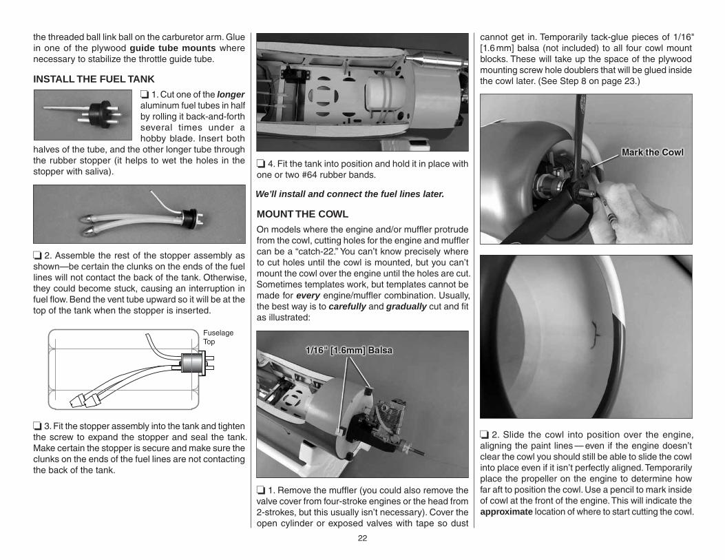
❏ 1. Remove the muffl er (you could also remove the valve cover from four-stroke engines or the head from 2-strokes, but this usually isn’t necessary). Cover the open cylinder or exposed valves with tape so dust
cannot get in. Temporarily tack-glue pieces of 1/16" [1.6 mm] balsa (not included) to all four cowl mount blocks. These will take up the space of the plywood mounting screw hole doublers that will be glued inside the cowl later. (See Step 8 on page 23.)
❏ 2. Slide the cowl into position over the engine, aligning the paint lines — even if the engine doesn’t clear the cowl you should still be able to slide the cowl into place even if it isn’t perfectly aligned. Temporarily place the propeller on the engine to determine how far aft to position the cowl. Use a pencil to mark inside of cowl at the front of the engine. This will indicate the approximate location of where to start cutting the cowl.
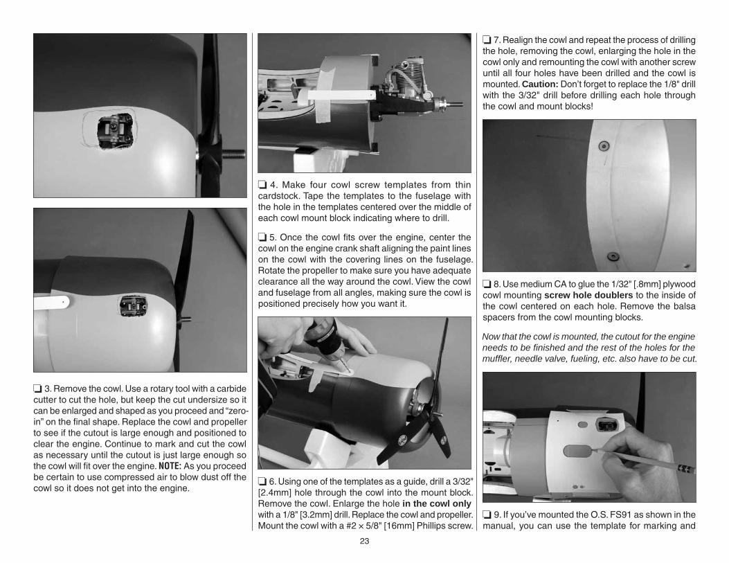
23
❏ 3. Remove the cowl. Use a rotary tool with a carbide cutter to cut the hole, but keep the cut undersize so it can be enlarged and shaped as you proceed and “zero-in” on the fi nal shape. Replace the cowl and propeller to see if the cutout is large enough and positioned to clear the engine. Continue to mark and cut the cowl as necessary until the cutout is just large enough so the cowl will fi t over the engine. NOTE: As you proceed be certain to use compressed air to blow dust off the cowl so it does not get into the engine.
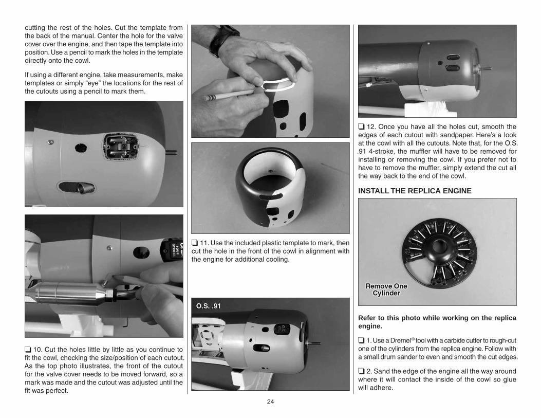
❏ 4. Make four cowl screw templates from thin cardstock. Tape the templates to the fuselage with the hole in the templates centered over the middle of each cowl mount block indicating where to drill.
❏ 5. Once the cowl fi ts over the engine, center the cowl on the engine crank shaft aligning the paint lines on the cowl with the covering lines on the fuselage. Rotate the propeller to make sure you have adequate clearance all the way around the cowl. View the cowl and fuselage from all angles, making sure the cowl is positioned precisely how you want it.
❏ 6. Using one of the templates as a guide, drill a 3/32" [2.4mm] hole through the cowl into the mount block. Remove the cowl. Enlarge the hole in the cowl only with a 1/8" [3.2mm] drill. Replace the cowl and propeller. Mount the cowl with a #2 × 5/8" [16mm] Phillips screw.
❏ 7. Realign the cowl and repeat the process of drilling the hole, removing the cowl, enlarging the hole in the cowl only and remounting the cowl with another screw until all four holes have been drilled and the cowl is mounted. Caution: Don’t forget to replace the 1/8" drill with the 3/32" drill before drilling each hole through the cowl and mount blocks!
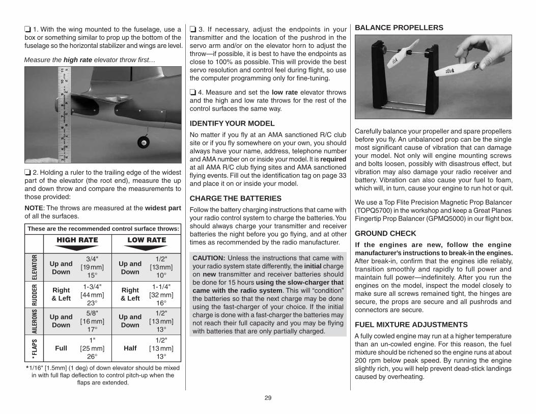
❏ 8. Use medium CA to glue the 1/32" [.8mm] plywood cowl mounting screw hole doublers to the inside of the cowl centered on each hole. Remove the balsa spacers from the cowl mounting blocks.
Now that the cowl is mounted, the cutout for the engine needs to be fi nished and the rest of the holes for the muffl er, needle valve, fueling, etc. also have to be cut.
❏ 9. If you’ve mounted the O.S. FS91 as shown in the manual, you can use the template for marking and
24
cutting the rest of the holes. Cut the template from the back of the manual. Center the hole for the valve cover over the engine, and then tape the template into position. Use a pencil to mark the holes in the template directly onto the cowl.
If using a different engine, take measurements, make templates or simply “eye” the locations for the rest of the cutouts using a pencil to mark them.
❏ 10. Cut the holes little by little as you continue to fi t the cowl, checking the size/position of each cutout. As the top photo illustrates, the front of the cutout for the valve cover needs to be moved forward, so a mark was made and the cutout was adjusted until the fi t was perfect.
❏ 11. Use the included plastic template to mark, then cut the hole in the front of the cowl in alignment with the engine for additional cooling.
❏ 12. Once you have all the holes cut, smooth the edges of each cutout with sandpaper. Here’s a look at the cowl with all the cutouts. Note that, for the O.S. .91 4-stroke, the muffl er will have to be removed for installing or removing the cowl. If you prefer not to have to remove the muffl er, simply extend the cut all the way back to the end of the cowl.
INSTALL THE REPLICA ENGINE
Refer to this photo while working on the replica engine.
❏ 1. Use a Dremel® tool with a carbide cutter to rough-cut one of the cylinders from the replica engine. Follow with a small drum sander to even and smooth the cut edges.
❏ 2. Sand the edge of the engine all the way around where it will contact the inside of the cowl so glue will adhere.

25
❏ 3. Drill 1/8" [3.2mm] holes through the valve covers and the crankcase for the valve guide tubes.
❏ 4. Fit, then glue the guide tubes into position with medium CA applied to the back side of the engine.
❏ 5. Use blocks or wood or something similar to support a lead pencil so the tip will be 1-1/4" to 1-3/8"
[32mm – 35mm] from the workbench. Use the pencil to draw a line around the inside of the cowl.
❏ 6. Without using any glue, fi t the replica engine down into the cowl, aligning it so it is level with the line you drew around the inside of the cowl.
❏ 7. Carefully mount the cowl to the fuselage without moving the replica engine—this may require removal of the drive washer from your engine.
❏ 8. Be certain the cutout in the replica engine aligns with the engine. Make any adjustments necessary.
❏ 9. Once satisfi ed with the fi t of the replica engine in the cowl and around the engine, remove the cowl with the replica engine. Wick thin CA around the replica engine to permanently glue it into the cowl.
❏ 10. If necessary, enlarge the hole in the middle of the replica engine to accommodate the drive washer on your engine. Here’s the fi nished installation.
❏ 11. Now you may cut and connect the fuel lines. The tank has been plumbed so there will be one line that connects the vent (on the top of the tank) to the pressure fi tting on the muffl er, another line connecting the tank to the carburetor and a third line for fueling/defueling. Close the fueling line (which can be reached through the bottom of the cowl for fueling and defueling) with an included fuel line plug and guide it through a hole in the cowl.
❏ 12. Note that an aluminum propeller hub is included with this kit. It may be used in place of the propeller nuts that come with your engine. Since it is not a locking system, however, be certain to use a small amount of threadlocker on the threads and securely tighten the hub with the included torque bar.
FINAL RADIO/RETRACT INSTALLATION
Refer to this photo while fi nishing your installation.
❏ 1. Take a few minutes to plan and visualize the rest of your radio installation, thinking about accessibility of the on/off switch and charge receptacle from outside the model. Mount the Rx battery and receiver using whatever methods have proven to work for you—1/4" [6.5mm] R/C foam is recommended for the battery held

26
down with a strap made from the included Velcro® hook-and-loop material. Most modern receivers are okay with double-sided foam adhesive tape, but always consult the instructions that came with your radio system. Connect the servos and switch to the receiver and make sure all the wires are smartly routed so as not to interfere with the pushrods or any other components.
❏ 2. Mount the air valve to the plywood valve mount. Mount an 0-80 threaded ball link ball to the valve with an 8-80 nut and a drop of threadlocker. Connect the air lines to the fi ttings on the valve before gluing the assembly into position on the servo tray in the fuselage.
❏ 3. Connect the air control valve to a servo with a screw-lock connector and a nylon ball link—the valve doesn’t slide far, so mount the screw-lock to the inner hole on the servo arm.
❏ 4. Mount the fi ll valve to the included plywood fi ll valve mount. Use a sharp hobby knife or a 5/16" brass
tube sharpened on the end to cut a hole in the side of the fuselage where the valve will be mounted. Glue the valve mount to the inside of the fuselage with the valve in the hole.
❏ 5. Connect approximately 10" [250mm] of air line to the air tank. Use RTV silicone or other non-permanent adhesive to glue in the tank.
❏ 6. Connect the rest of the lines and fi ttings to make the air system operational. Sometime before you fl y the model, pressurize the system by fi lling the air tank and cycle the gear a few times to make sure everything works. Be sure to cycle the gear with the plane right-side-up as well. Make any adjustments necessary.
INSTALL THE COCKPIT
The interior cockpit included with the Top Flite Corsair is just a start—without any additional work it covers the interior with some color and detail. However, modelers wishing to add even more scale detail should study cockpit interior photos of a full-size Corsair and take it from there.
❏ 1. Determine what, if any, additional detail or painting you may wish to add. Some detail could be added after the cockpit has been installed, but will be easier to do before.
❏ 2. After adding any additional details, glue the separate parts of the cockpit interior into position, starting with the back, then the sides.
❏ 3. Glue in the instrument panel—here, it is best to use something fl exible such as RTV silicone rubber or R/C-56 canopy glue.

27
❏ 4. Test-fi t the cockpit fl oor to the sides under the pushrods. Use fl exible glue (R/C-56 canopy glue or RTV silicone) to glue the fl oor into position.
❏ 5. Decide whether or not you will be installing a pilot and how to glue him in. A Top Flite 1/7-scale WWII pilot (GPMQ9117) was used for this model. He was securely glued to a balsa sheet that was painted fl at black. The sheet was glued into position to the cockpit sides with R/C-56.
❏ 7. Attach the canopy—it may be permanently glued to the fuselage with CA or R/C 56 canopy glue, or held in place with screws. Screws are usually preferred because this allows future access to the cockpit if ever necessary. To glue the canopy into position, simply hold it in place with tape until the glue dries. If screwing the canopy down, tape it into position and drill 1/16" [1.6mm] holes through the canopy and fuselage where desired. Remove the canopy and enlarge the holes in the canopy only with a 3/32" [2.4mm] drill. Temporarily screw #2 screws into the fuselage, remove, and add a drop of thin CA to each hole. Allow to harden and mount the canopy.
APPLY THE DECALS
Use window cleaner to apply the decals wet as described below. This will allow precise positioning and remove air bubbles from under the decals, making for a perfect application.
❏ 1. Make sure the surfaces where the decals are to be applied are clean and free of any residual glue or oily fi ngerprints. Also make sure your hands are clean.
❏ 2. Peel the decal from the sheet and immediately spray the back with window cleaner. Apply the decal and position it precisely where desired—the window cleaner will make it easy to slide the decal around, getting it exactly where you want it.
❏ 3. Once the decal is in position, use a paper towel to lightly squeegee out most of the window cleaner from underneath the decal.
❏ 4. Once the decal seems to be partially stuck, use a piece of soft balsa to squeegee out the rest of the window cleaner and air bubbles from under the decal. Allow the decal to sit for a few hours before fl ying.
❏ 5. If there are any edges around any of the decals that won’t seem to lay down all the way, you may lightly go over those areas with a covering iron with a cover sock on low heat (around 150°F [65°C]).
GET THE MODEL READY TO FLY
BALANCE THE MODEL (C.G.)
More than any other factor, the C.G. (balance point) can have the greatest effect on how a model fl ies, and may determine whether or not your fi rst fl ight will be successful. If you value this model and wish to enjoy it for many fl ights, DO NOT OVERLOOK THIS IMPORTANT PROCEDURE. A model that is not properly balanced will be unstable and possibly unfl yable.
At this stage the model should be in ready-to-fl y condition with all of the systems in place including the engine with propeller and propeller hub, landing gear/retracts, the complete radio system and decals.

28
TOP OF WING
4-1/8" [105mm]
❏ 1. If you will be using a Great Planes C.G. Machine™ to check the balance point, set the rulers to 4-1/8" [105mm]. If not using a Great Planes C.G. Machine, and if you haven’t already done so, use a straightedge and a fi ne-point felt-tip pen to mark the balance point on the top of the wing panels 4-1/8" [105mm] back from the leading edges and place 1/16" to 1/8" [1.5 to 3mm] strips of tape over the lines so you will be able to feel the balance point with your fi ngers when lifting the model upside-down.
This is where your model should balance for the fi rst fl ights. Later, you may wish to experiment by shifting the C.G. up to 3/8" [10mm] forward or 3/8" [10mm] back to change the fl ying characteristics. Moving the C.G. forward may improve the smoothness and stability, but the model may then require more speed for takeoff and make it more diffi cult to slow for landing. Moving the C.G. aft makes the model more maneuverable, but could also cause it to become too diffi cult to control. In any case, start at the recommended balance point and do not at any time balance the model outside the specifi ed range.
❏ 2. If you haven’t done so already, mount the wing to the fuselage. If you have retractable landing gear, retract the gear into the wing. With all parts of the model installed, the model ready to fl y and an empty
fuel tank, place the model on a CG Machine or lift it with your fi ngers on the balance points marked by the thin strips of tape.
❏ 3. If the tail drops, the model is “tail heavy” and weight must be added to the nose to balance. If the nose drops, the model is “nose heavy” and weight must be added to the tail to balance. If any additional weight is required to get the model to balance, use Great Planes “stick-on” lead (GPMQ4485). The best place to add stick-on nose weight is to the fi rewall and the best place to add tail weight is inside the tail cover. Begin by placing incrementally increasing amounts of weight on the fuselage over the location where it will be permanently attached inside until you can get it to balance. Once you have determined the amount of weight required (or the battery positioning if possible), it can be permanently attached. Note: Do not rely upon the adhesive on the back of the lead weight to permanently hold it in place. Over time, the adhesive may weaken causing the weight to fall off. Use #2 sheet metal screws, RTV silicone or epoxy to permanently hold the weight in place.
❏ 4. IMPORTANT: Once you’ve added any additional weight, recheck the C.G.
BALANCE THE MODEL LATERALLY
❏ 1. With the wing level, lift the model under the tail and by the propeller shaft. Do this several times.
❏ 2. If one wing always drops when you lift the model, it means that side is heavy. Balance the airplane by adding weight to the other wing tip. An airplane that has been laterally balanced will track better in fl ight and maintain its heading better during maneuvers when the plane is climbing.
PREFLIGHT
CHECK THE CONTROL DIRECTIONS
❏ 1. Turn on the transmitter and receiver and center the trims. If necessary, remove the servo arms from the servos and reposition them so they are centered. Reinstall the screws that hold on the servo arms.
❏ 2. With the transmitter and receiver still on, check all the control surfaces to see if they are centered. If necessary, adjust the clevises on the pushrods to center the control surfaces.
FULL THROTTLE
RUDDERMOVESRIGHT
ELEVATOR MOVES DOWN
RIGHT AILERON MOVES UPLEFT AILERONMOVES DOWN
4-CHANNEL RADIO SETUP (STANDARD MODE 2)
❏ 3. Make certain that the control surfaces and the carburetor respond in the correct direction as shown in the diagram. If any of the controls respond in the wrong direction, use the servo reversing in the transmitter to reverse the servos connected to those controls. Be certain the control surfaces have remained centered. Adjust if necessary.
SET THE CONTROL THROWS
To ensure a successful fi rst fl ight, set up your Corsair .60 ARF according to the control throws provided. The throws have been determined through record-keeping and fl ight testing, allowing the model to perform in the manner in which it was intended. If, after you have become accustomed to the way the Corsair fl ies, you would like to change the throws to suit your taste, that is fi ne. However, too much control throw could make the model too responsive and diffi cult to control, so remember, “more is not always better.”
29
❏ 1. With the wing mounted to the fuselage, use a box or something similar to prop up the bottom of the fuselage so the horizontal stabilizer and wings are level.
Measure the high rate elevator throw fi rst…
❏ 2. Holding a ruler to the trailing edge of the widest part of the elevator (the root end), measure the up and down throw and compare the measurements to those provided:
NOTE: The throws are measured at the widest part of all the surfaces.
These are the recommended control surface throws:
ELEV
ATOR
HIGH RATE LOW RATE
Up andDown
3/4"[19mm]
15°
Up andDown
1/2"[13mm]
10°
Up andDown
5/8"[16 mm]
17°
Up andDown
Full Half
1/2"[13 mm]
13°
1"[25 mm]
26°
1/2"[13 mm]
13°
Right& Left
1-3/4"[44mm]
23°
Right& Left
1-1/4"[32 mm]
16°RUDD
ERAI
LERO
NS*F
LAPS
*1/16" [1.5mm] (1 deg) of down elevator should be mixed in with full flap deflection to control pitch-up when the
flaps are extended.
❏ 3. If necessary, adjust the endpoints in your transmitter and the location of the pushrod in the servo arm and/or on the elevator horn to adjust the throw—if possible, it is best to have the endpoints as close to 100% as possible. This will provide the best servo resolution and control feel during fl ight, so use the computer programming only for fi ne-tuning.
❏ 4. Measure and set the low rate elevator throws and the high and low rate throws for the rest of the control surfaces the same way.
IDENTIFY YOUR MODEL
No matter if you fl y at an AMA sanctioned R/C club site or if you fl y somewhere on your own, you should always have your name, address, telephone number and AMA number on or inside your model. It is required at all AMA R/C club fl ying sites and AMA sanctioned fl ying events. Fill out the identifi cation tag on page 33 and place it on or inside your model.
CHARGE THE BATTERIES
Follow the battery charging instructions that came with your radio control system to charge the batteries. You should always charge your transmitter and receiver batteries the night before you go fl ying, and at other times as recommended by the radio manufacturer.
CAUTION: Unless the instructions that came with your radio system state differently, the initial charge on new transmitter and receiver batteries should be done for 15 hours using the slow-charger that came with the radio system. This will “condition” the batteries so that the next charge may be done using the fast-charger of your choice. If the initial charge is done with a fast-charger the batteries may not reach their full capacity and you may be fl ying with batteries that are only partially charged.
BALANCE PROPELLERS
Carefully balance your propeller and spare propellers before you fl y. An unbalanced prop can be the single most signifi cant cause of vibration that can damage your model. Not only will engine mounting screws and bolts loosen, possibly with disastrous effect, but vibration may also damage your radio receiver and battery. Vibration can also cause your fuel to foam, which will, in turn, cause your engine to run hot or quit.
We use a Top Flite Precision Magnetic Prop Balancer (TOPQ5700) in the workshop and keep a Great Planes Fingertip Prop Balancer (GPMQ5000) in our fl ight box.
GROUND CHECK
If the engines are new, follow the engine manufacturer’s instructions to break-in the engines. After break-in, confi rm that the engines idle reliably, transition smoothly and rapidly to full power and maintain full power—indefi nitely. After you run the engines on the model, inspect the model closely to make sure all screws remained tight, the hinges are secure, the props are secure and all pushrods and connectors are secure.
FUEL MIXTURE ADJUSTMENTS
A fully cowled engine may run at a higher temperature than an un-cowled engine. For this reason, the fuel mixture should be richened so the engine runs at about 200 rpm below peak speed. By running the engine slightly rich, you will help prevent dead-stick landings caused by overheating.

30
RANGE CHECK
Ground check the operational range of your radio before the fi rst fl ight of the day. With the transmitter antenna collapsed and the receiver and transmitter on, you should be able to walk at least 100 feet away from the model and still have control. (If using a 2.4GHz radio system, refer to the radio manufacturer's manual.) Have an assistant stand by your model and, while you work the controls, tell you what the control surfaces are doing. Repeat this test with the engines running at various speeds with an assistant holding the model, using hand signals to show you what is happening. If the control surfaces do not respond correctly, do not fl y! Find and correct the problem fi rst. Look for loose servo connections or broken wires, corroded wires on old servo connectors, poor solder joints in your battery pack or a defective cell, or a damaged receiver crystal from a previous crash.
ENGINE SAFETY PRECAUTIONS
Failure to follow these safety precautions may result in severe injury to yourself and others.
● Keep all engine fuel in a safe place, away from high heat, sparks or fl ames, as fuel is very fl ammable. Do not smoke near the engine or fuel; and remember that engine exhaust gives off a great deal of deadly carbon monoxide. Therefore do not run the engine in a closed room or garage.
● Get help from an experienced pilot when learning to operate engines.
● Use safety glasses when starting or running engines.
● Do not run the engine in an area of loose gravel or sand; the propeller may throw such material in your face or eyes.
● Keep your face and body as well as all spectators away from the plane of rotation of the propeller as you start and run the engine.
● Keep these items away from the prop: loose clothing, shirt sleeves, ties, scarfs, long hair or loose objects such as pencils or screwdrivers that may fall out of shirt or jacket pockets into the prop.
● Use a “chicken stick” or electric starter to start the engine. Do not use your fi ngers to fl ip the propeller. Make certain the glow plug clip or connector is secure so that it will not pop off or otherwise get into the running propeller.
● Make all engine adjustments from behind the rotating propeller.
● The engine gets hot! Do not touch it during or right after operation. Make sure fuel lines are in good condition so fuel will not leak onto a hot engine, causing a fi re.
● To stop a glow engine, cut off the fuel supply by closing off the fuel line or following the engine manufacturer’s recommendations. Do not use hands, fi ngers or any other body part to try to stop the engine. To stop a gasoline powered engine an on/off switch should be connected to the engine coil. Do not throw anything into the propeller of a running engine.
AMA SAFETY CODE (excerpts)Read and abide by the following excerpts from the Academy of Model Aeronautics Safety Code. For the complete Safety Code refer to Model Aviation magazine, the AMA web site or the Code that came with your AMA license.
GENERAL
1) I will not fl y my model aircraft in sanctioned events, air shows, or model fl ying demonstrations until it has been proven to be airworthy by having been previously, successfully fl ight tested.
2) I will not fly my model aircraft higher than approximately 400 feet within 3 miles of an airport without notifying the airport operator. I will give right-of-way and avoid fl ying in the proximity of full-scale
aircraft. Where necessary, an observer shall be utilized to supervise fl ying to avoid having models fl y in the proximity of full-scale aircraft.
3) Where established, I will abide by the safety rules for the fl ying site I use, and I will not willfully and deliberately fl y my models in a careless, reckless and/or dangerous manner.
5) I will not fl y my model unless it is identifi ed with my name and address or AMA number, on or in the model. Note: This does not apply to models while being fl own indoors.
7) I will not operate models with pyrotechnics (any device that explodes, burns, or propels a projectile of any kind).
RADIO CONTROL
1) I will have completed a successful radio equipment ground check before the fi rst fl ight of a new or repaired model.
2) I will not fl y my model aircraft in the presence of spectators until I become a qualifi ed fl ier, unless assisted by an experienced helper.
3) At all fl ying sites a straight or curved line(s) must be established in front of which all fl ying takes place with the other side for spectators. Only personnel involved with fl ying the aircraft are allowed at or in the front of the fl ight line. Intentional fl ying behind the fl ight line is prohibited.
4) I will operate my model using only radio control frequencies currently allowed by the Federal Communications Commission.
5) I will not knowingly operate my model within three miles of any pre-existing fl ying site except in accordance with the frequency sharing agreement listed [in the complete AMA Safety Code].
9) Under no circumstances may a pilot or other person touch a powered model in fl ight; nor should any part of the model other than the landing gear, intentionally touch the ground, except while landing.
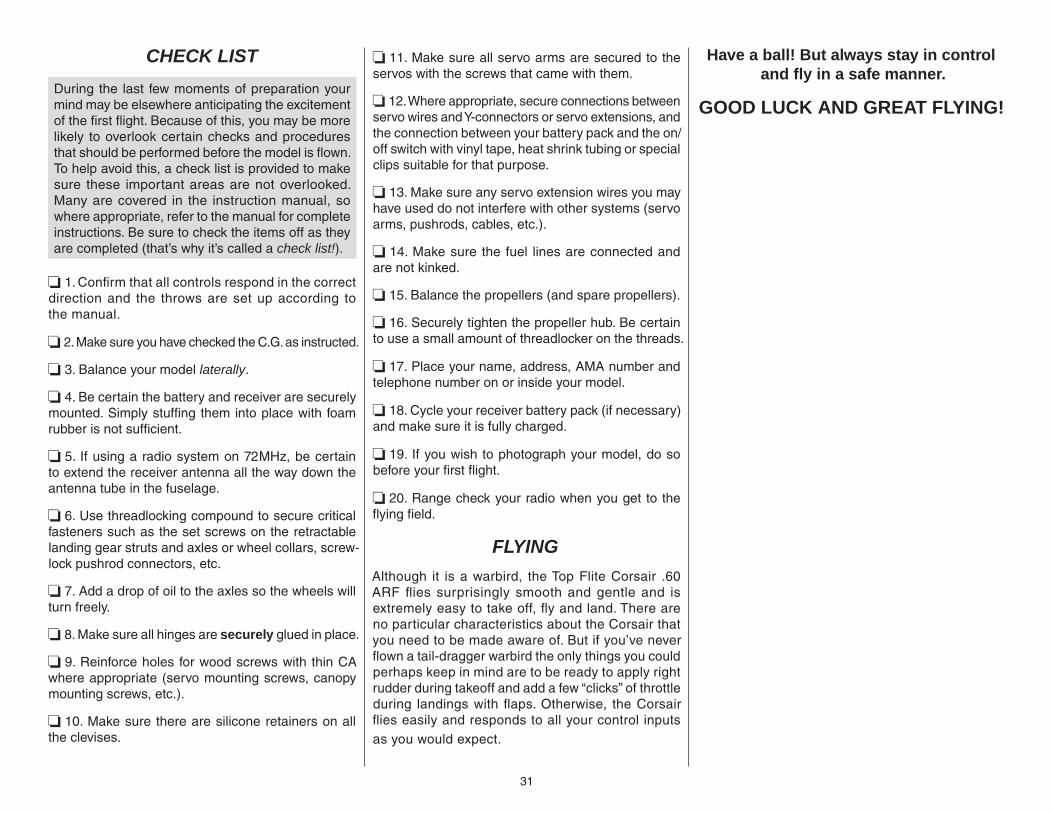
31
CHECK LIST
During the last few moments of preparation your mind may be elsewhere anticipating the excitement of the fi rst fl ight. Because of this, you may be more likely to overlook certain checks and procedures that should be performed before the model is fl own. To help avoid this, a check list is provided to make sure these important areas are not overlooked. Many are covered in the instruction manual, so where appropriate, refer to the manual for complete instructions. Be sure to check the items off as they are completed (that’s why it’s called a check list!).
❏ 1. Confi rm that all controls respond in the correct direction and the throws are set up according to the manual.
❏ 2. Make sure you have checked the C.G. as instructed.
❏ 3. Balance your model laterally.
❏ 4. Be certain the battery and receiver are securely mounted. Simply stuffi ng them into place with foam rubber is not suffi cient.
❏ 5. If using a radio system on 72MHz, be certain to extend the receiver antenna all the way down the antenna tube in the fuselage.
❏ 6. Use threadlocking compound to secure critical fasteners such as the set screws on the retractable landing gear struts and axles or wheel collars, screw-lock pushrod connectors, etc.
❏ 7. Add a drop of oil to the axles so the wheels will turn freely.
❏ 8. Make sure all hinges are securely glued in place.
❏ 9. Reinforce holes for wood screws with thin CA where appropriate (servo mounting screws, canopy mounting screws, etc.).
❏ 10. Make sure there are silicone retainers on all the clevises.
❏ 11. Make sure all servo arms are secured to the servos with the screws that came with them.
❏ 12. Where appropriate, secure connections between servo wires and Y-connectors or servo extensions, and the connection between your battery pack and the on/off switch with vinyl tape, heat shrink tubing or special clips suitable for that purpose.
❏ 13. Make sure any servo extension wires you may have used do not interfere with other systems (servo arms, pushrods, cables, etc.).
❏ 14. Make sure the fuel lines are connected and are not kinked.
❏ 15. Balance the propellers (and spare propellers).
❏ 16. Securely tighten the propeller hub. Be certain to use a small amount of threadlocker on the threads.
❏ 17. Place your name, address, AMA number and telephone number on or inside your model.
❏ 18. Cycle your receiver battery pack (if necessary) and make sure it is fully charged.
❏ 19. If you wish to photograph your model, do so before your fi rst fl ight.
❏ 20. Range check your radio when you get to the fl ying fi eld.
FLYING
Although it is a warbird, the Top Flite Corsair .60 ARF fl ies surprisingly smooth and gentle and is extremely easy to take off, fl y and land. There are no particular characteristics about the Corsair that you need to be made aware of. But if you’ve never fl own a tail-dragger warbird the only things you could perhaps keep in mind are to be ready to apply right rudder during takeoff and add a few “clicks” of throttle during landings with fl aps. Otherwise, the Corsair fl ies easily and responds to all your control inputs as you would expect.
Have a ball! But always stay in controland fl y in a safe manner.
GOOD LUCK AND GREAT FLYING!

3232
Componentsin Fuselage
Componentsin Wing
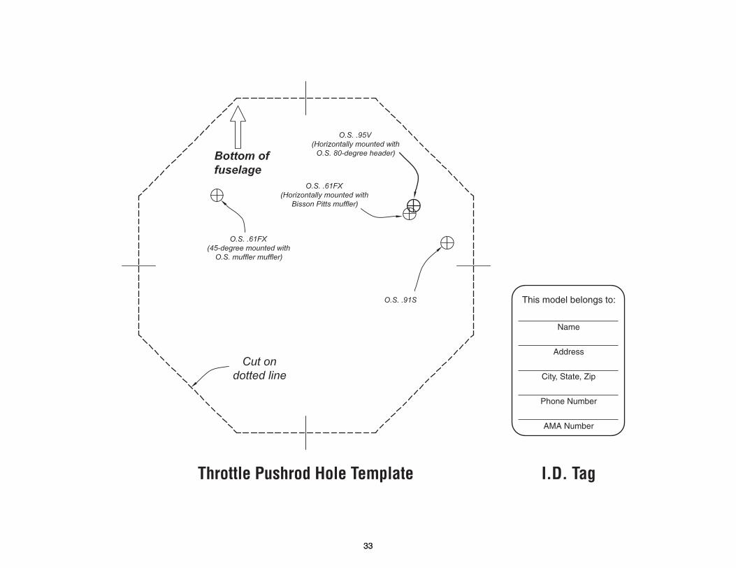
Throttle Pushrod Hole Template I.D. Tag
This model belongs to:
Name
Address
City, State, Zip
Phone Number
AMA Number
3333

3434

35
Cowl Hole Template (For O.S. .91 4-stroke)

Cowl Hole Template (For O.S. .95V)