instruction manual - harris products group harris products group pty ltd., australia
TRANSCRIPT

HARRIS
Harris Products Group Pty Ltd., Australia.
INSTRUCTION MANUAL For Gas Welding, Cutting, Brazing & Heating
Torches.
www.harrisproductsgroup.com.au
IMPORTANT:
For your own safety read
these instructions.
Failure to do so can lead to
serious injury.
THE HARRIS PRODUCTS GROUP

HARRIS
Harris Products Group Pty Ltd., Australia.
HARRIS
Harris Products Group Pty Ltd., Australia.
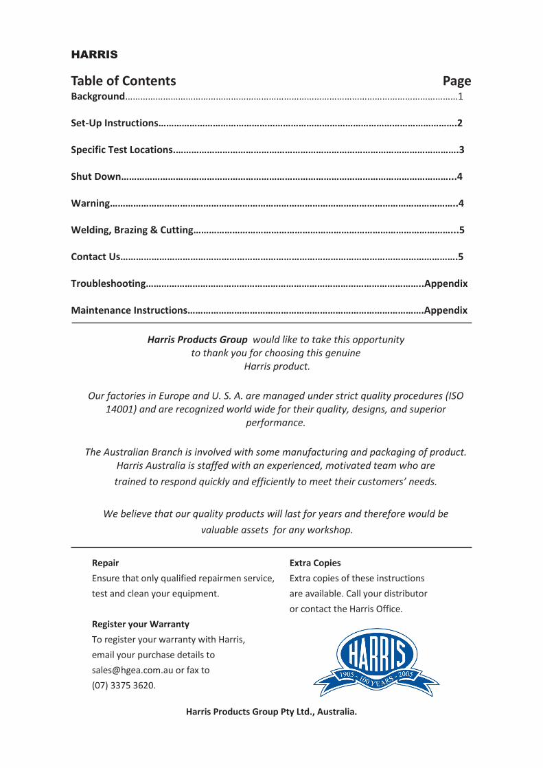
Table of Contents Page Background……………………………………………………………………………………………………………………1
Set-Up Instructions…………………………………………………………………………………………………….2
Specific Test Locations.……………………………………………………………………………………………….3
Shut Down………………………………………………………………………………………………………………...4
Warning……………………………………………………………………………………………………………………..4
Welding, Brazing & Cutting………………………………………………………………………………………...5
Contact Us………………………………………………………………………………………………………………….5
Troubleshooting……………………………………………………………………………………………..Appendix
Maintenance Instructions……………………………………………………………………………….Appendix
Harris Products Group would like to take this opportunity to thank you for choosing this genuine
Harris product.
Our factories in Europe and U. S. A. are managed under strict quality procedures (ISO 14001) and are recognized world wide for their quality, designs, and superior
performance.
The Australian Branch is involved with some manufacturing and packaging of product. Harris Australia is staffed with an experienced, motivated team who are
trained to respond quickly and efficiently to meet their customers’ needs.
We believe that our quality products will last for years and therefore would be
valuable assets for any workshop.
Repair Extra Copies
Ensure that only qualified repairmen service, Extra copies of these instructions
test and clean your equipment. are available. Call your distributor
or contact the Harris Office.
Register your Warranty
To register your warranty with Harris,
email your purchase details to
[email protected] or fax to
(07) 3375 3620.

HARRIS
Harris Products Group Pty Ltd., Australia.
BACKGROUND What Regulators do: Break down unusable high pressure to a usable lower pressure Keeps low pressure constant Compensate for supply pressure changes Acts as a safety device for the operator & cylinder How Regulators work: Use energy “stored” in the supply cylinder Adjusting screw/knob sets delivery pressure Right hand gauge displays cylinder pressure Left hand gauge displays the deliver/outlet pressure as adjusting knob is screwed in clock-
wise Adjusting knob deflects diaphragm - opens seat allows pressure into low pressure side Hoses: Carry gas from the supply to the handle for operation. They should be of good quality with
good fit up to regulator/flashback arrestor Hose/fittings/joints should be checked for leaks on a regular basis Handles: These items allow various attachments to be fitted which allow the operator to complete
tasks ie. mixer—brazing tips and cutting attachments Mixer: Mix the two gases prior to the tip tube Tip Tube: Carry the mixed gases to the brazing/heating tip Brazing/Heating Tip: Produces a flame shape to aid the transfer of heat/energy into the job being undertaken Quality of the flame shape is governed by quality/condition of the tip and operator adjust-
ment Cutting Attachment: Allows the operator to cut/gouge steel, different tip styles and sizes are available Quality of cut will depend on operator skill and quality and condition of tip and compli-
ance to settings Flashguards: Prevent the reverse flow of gases from the handle to either of the gas hoses, an explosive
mixture may result which could cause personal injury or fire Flashback Arrestor: Include a built-in check valve to prevent reverse flow and a sintered metal filter to extin-
guish the flame should a flashback occur.
Page 1

HARRIS
Harris Products Group Pty Ltd., Australia.
Set Up Instructions Reference Document AS 4839-2001 1. Check that all equipment connections and especially both cylinder valve outlets and regulator inlets are clean and free from oil and grease. 2. ‘Crack’ (briefly open and close) cylinder valves (Fig 1). 3. Screw the regulators into cylinder valve outlet using an appropriate spanner (Fig 2). 4. Fit flashback arrestors and hose to regulators (Fig. 3). 5. Adjust the oxygen regulator to allow a small flow through the hose then release the control. Repeat for the fuel gas regulator (this blows off dust and chalk from inside the hoses). (Fig 4.) 6. Connect the handle to the hose end (Fig 5). 7. Connect the required attachments, tips and
nozzles to the handle & tighten (Fig 6. next page).
Leak Testing Procedure: - Initial System Pressurization.
a) Both cylinder supply valves should be fully closed. (Fig. 1).
b) Both regulator pressure adjusting knobs shall be turned anti-clockwise until fully disen-gaged with spring/diaphragm. Knob will feel loose.
c) The valves on the handle shall be fully closed (Fig. 9 over page).
d) Each cylinder gas supply valve shall be slowly opened one end at a time. The low pressure gauge on each regulator shall be observed. If pressure is registered on either or both low pressure gauge, this indicates a faulty regula-tor—internal seat not closing. Replace faulty regulator and re-start the pressurization pro-cedure.
Note: If the system indicates a leak free seat state screw in the fuel gas regulator pressure adjusting knob until a pressure of 100KPA is achieved. Do the same for the oxygen regulator.
e) Turn both gas cylinder supply valves off fully (Fig 1).
f) Observe the pressure gauges on each regulator of a nominal 1 min. If a drop in pressure is indicated, then there is a leak in the system. Comply with specific test locations procedure to find the leak.
Figure 1. Opening Cylinder Valve
Figure 3. Attaching Fuel Gas Regulator.
Figure 2.
Figure 4.
Page 2

HARRIS
Harris Products Group Pty Ltd., Australia.
Specific test locations: Test for leaks at the following points (using a suitable leak de-tecting solution)
a) Between both the gas cylinder supply valves and the regulator connections. b) Between the regulator outlet connections and the welding hose connection. c) Between the welding hoses and the hose connections on both ends. d) Between the blowpipe inlet connections
and the welding hose connections. e) Around the spindles of all blowpipe and
cutting attachment valves. f) At the connection joint between the
blowpipe and the welding cutting or heating attachment.
g) At the tip.
Note: If leaks are detected at any of these points then necessary adjustments, repairs or replacements shall be made before proceeding.
8. Turn on each cylinder valve. Slowly pres-sure will be displayed in the right hand gauge for oxygen and acetylene. LPG/Propane is filled by weight therefore there is no cylinder pressure.
9. Adjust regulator to required pressure for the task at hand (Fig. 8), refer to Table 2 to obtain recommended pressures.
Fig. 8 Adjusting Regulator
Figure 9. Handle Valve Example
10. Purge oxygen and fuel gas individually to ensure there is no mix gases in handle before fitting attachments and lighting torch. (Fig. 9)
11. Install correct size tip (Fig. 6 above ) for metal thickness to be welded or cut. Make sure the tip seat is free of nicks or burrs. Welding tips should be hand- tightened only. Cutting tips should be wrench tightened.
11a) Open handle fuel gas valve approximately one quarter turn and ignite fuel gas. Close valve slightly if flame blows off tip.
11b) Crack oxygen valve and open until feathery, secondary cone disappears (Fig 11). Inner cone will be carbonizing at first stage. As more oxygen is added a neutral flame is achieved (Fig. 12).
Fig. 11) Carbonizing
Fig. 12 Neutral
Fig. 13 Oxidizing
Page 3

HARRIS
Harris Products Group Pty Ltd., Australia.
11c) Alternately open each valve to bring flame intensity up to the desired point. Maintain the neutral position for the best results.
11d) If you add too much oxygen you will shorten the inner flame and create the ‘oxidizing’ position. (Fig. 13) This will damage the tip and interfere with the task i.e. bad cut face/burn out tip.
Shut Down Procedure 1. Close torch oxygen valve. The close the fuel gas valve (Fig 9), which will extinguish the flame.
2. Turn off cylinder valve (Fig 1).
3. Open valves on handle / cutting attach-ment to vent hoses separately. Re-close valves. (Fig. 14)
4. Return the regulator adjusting screw to zero delivery position.
5. Check equipment for damage. Any dam-age should be reported and equipment tagged as defective. Equipment MUST be repaired prior to re-use.
6. Return equipment and cylinders to a place of storage.
7. Check to ensure that the cylinder valves are properly closed and there is no leakage of gas.
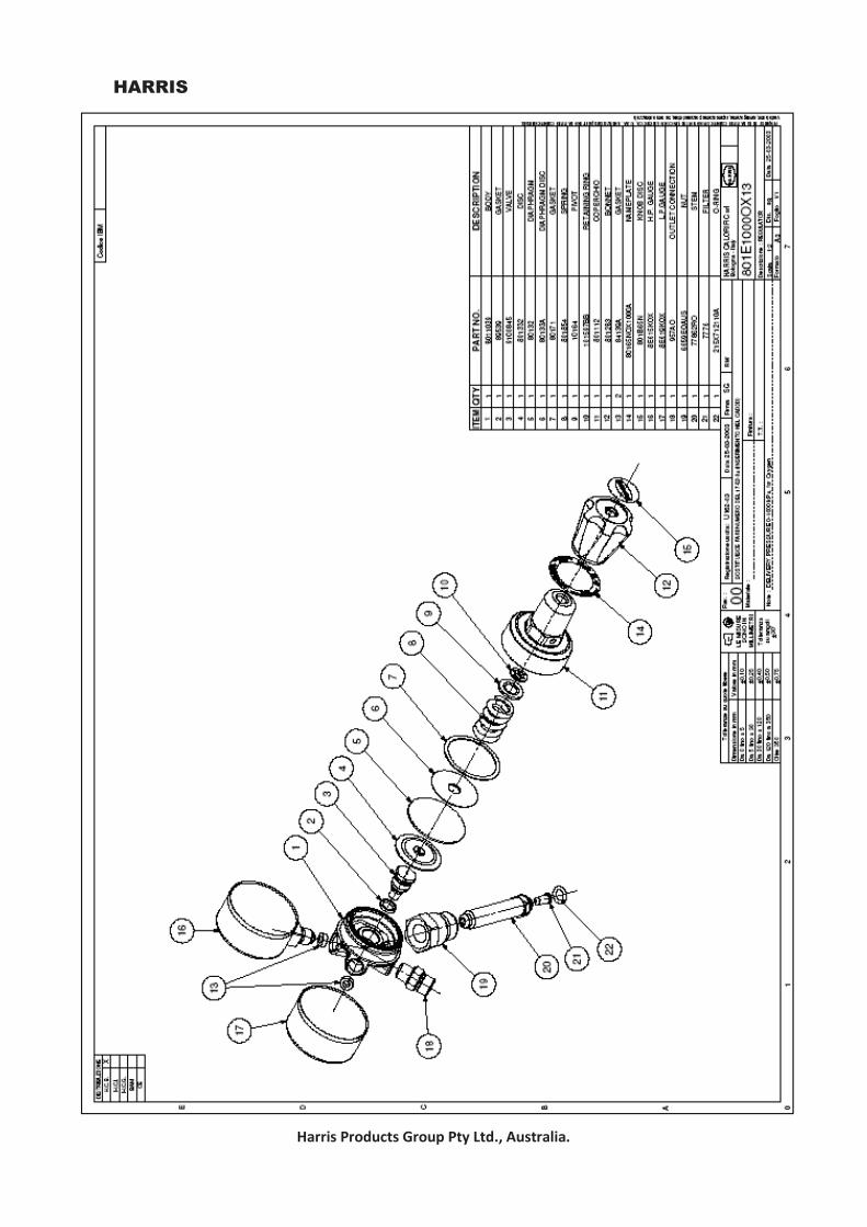
Spare Parts A range of small parts are available for all equip-ment, the attached drawing is a typical example. Please contact your local Harris Distributor or our friendly Customer Service Team at Harris Prod-ucts Group on (07) 3375 3670 or email [email protected].
WARNING DO NOT—attempt to repair or substitute parts on equipment, particularly the regulators. Spe-cial techniques and tools are needed to safely repair oxy-fuel gas welding and cutting appara-tus.
DO NOT—handle oxygen regulators, oxygen cyl-inders, valves or any other equipment with oily or greasy hands or gloves. Oxygen will react with oil and grease in such a manner that will easily result in fire or explosion.
DO NOT—lay or store oxygen regulators or other oxygen equipment on oily or greasy surfaces. The equipment can become contaminated with oil or grease which might result in a fire or explo-sion.
DO NOT—use acetylene pressure above 150kpa. Acetylene pressures above 150kpa can result in a fire or explosion.
DO NOT—empty the oxygen cylinder below 250kpa. If the oxygen cylinder is allowed to be-come completely empty, it will lose its positive pressure and contamination may enter the cylin-der and create an unsafe condition.
DO NOT—change regulators from one gas service to another or replace a pressure gauge with one taken from any other service. Contamination resulting in a fire or explosion can take place by changing pressure gauges or regulators from one service to the other.
DO NOT– leave pressure on a regulator when not in use.
IN CONCLUSION Treat your gas apparatus with respect. All manu-facturers try to produce the safest equipment possible; but when it is not properly used, serious accidents do occur. Also, make sure check valves are on every torch. They’ll help you during those times when your hands are working, but your head is not.
Figure 1. Opening Cylinder
Figure 14. Open valves & Purge gas
Page 4

HARRIS
Harris Products Group Pty Ltd., Australia.
Gas Welding , Brazing & Cutting Basic Gas Welding Procedures Gas Welding.
Gas welding is a method of joining similar metals by heating the adjacent surfaces to the melting point with an oxy-acetylene flame, and allowing the two parts to fuse together, with a filler metal being required on materials 5mm thick or more. The resulting weld is as strong as the parent metal. Clean all metal.
All metal should be cleaned before welding. Oil, grease, rust, scale, or other Impurities affect the weld quality, or tensile strength. Metal 5mm or more thick should be bev-eled before welding, and when beveled sides are joined, a filler rod of the same material is necessary. Welding Tip Chart.
The welding tip chart shows the proper tip sizes and oxygen and acetylene pressures related to the thickness of material to be welded.
The chart should serve as a handy guide to be re-ferred to often. If too large a tip is used and the flame softened, the tip heats up unnecessarily and is often accompanied by a popping noise which splatters the weld puddle.
Too hot a flame burns the steel, and too small a flame will not heat the metal to the proper tem-perature. (Refer Table 2 appendix) Welding Rod.
Welding rods are available for all types of welding, including mild steel, cast iron and aluminium. The size needed will be determined by the type of weld, the thickness of the metal, and the amount of filler metal required.
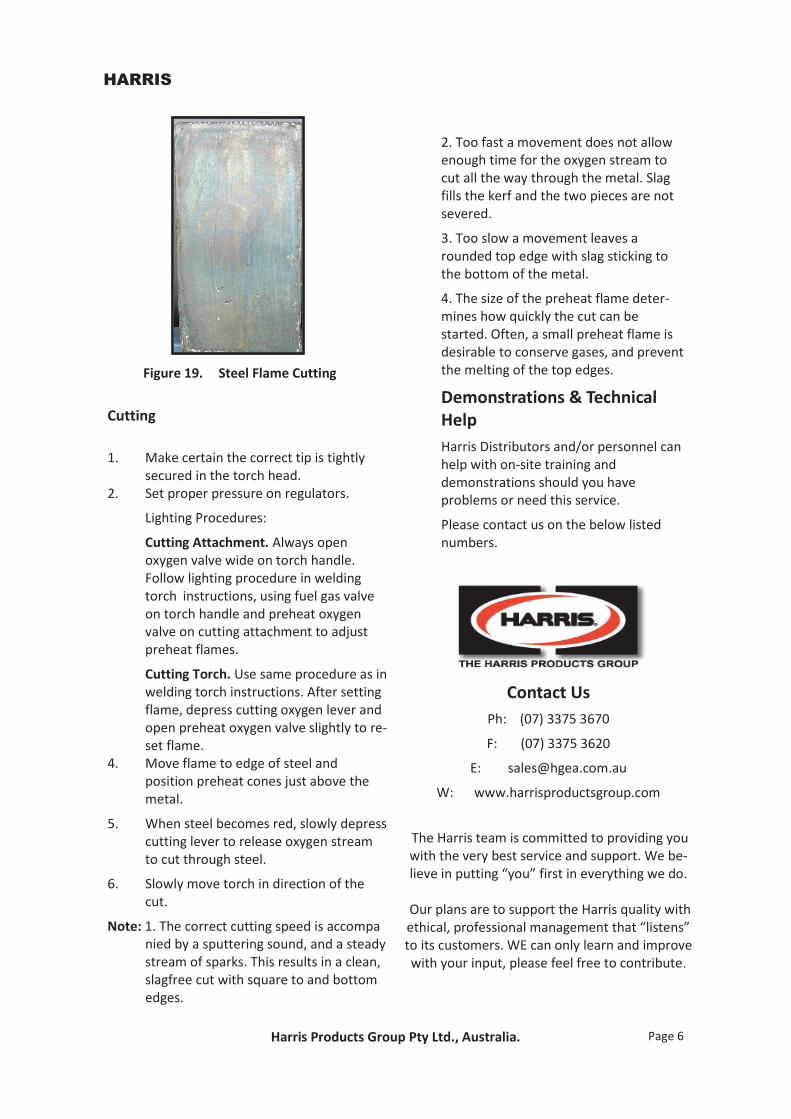
Steel Flame Cutting Steel flame cutting is a simple process that can be quickly mastered.
Only carbon steel can be cut with the oxy-fuel gas method, since cast iron, stainless steel, aluminium, brass and other ferrous metals do not burn the way steel does.
The way to cut steel is to heat it to its kin-dling temperature (a red colour) and then burn it rapidly with pure oxygen. A cutting torch provides both the preheat flames and pure oxygen cutting stream.
Fuel gas and oxygen are combined in the torch head and burn at the torch tip with a flame temperature of 3000 c. These are the preheat flames.
The center hole in the cutting tip is for the pure oxygen, which flows through to cut the steel after the metal is sufficiently pre-heated. Note: Cutting Tips are available in a wide range of sizes, the proper size being determined by the steel thickness. Refer to the chart in appendix a guide for tip sizes, style and operating pressures.
Page 5
HARRIS
Harris Products Group Pty Ltd., Australia.
Cutting 1. Make certain the correct tip is tightly secured in the torch head. 2. Set proper pressure on regulators.
Lighting Procedures:
Cutting Attachment. Always open oxygen valve wide on torch handle. Follow lighting procedure in welding torch instructions, using fuel gas valve on torch handle and preheat oxygen valve on cutting attachment to adjust preheat flames.
Cutting Torch. Use same procedure as in welding torch instructions. After setting flame, depress cutting oxygen lever and open preheat oxygen valve slightly to re- set flame. 4. Move flame to edge of steel and position preheat cones just above the metal.
5. When steel becomes red, slowly depress cutting lever to release oxygen stream to cut through steel.
6. Slowly move torch in direction of the cut.
Note: 1. The correct cutting speed is accompa nied by a sputtering sound, and a steady stream of sparks. This results in a clean, slagfree cut with square to and bottom edges.
Figure 19. Steel Flame Cutting
2. Too fast a movement does not allow enough time for the oxygen stream to cut all the way through the metal. Slag fills the kerf and the two pieces are not severed.
3. Too slow a movement leaves a rounded top edge with slag sticking to the bottom of the metal.
4. The size of the preheat flame deter- mines how quickly the cut can be started. Often, a small preheat flame is desirable to conserve gases, and prevent the melting of the top edges.
Demonstrations & Technical Help
Harris Distributors and/or personnel can help with on-site training and demonstrations should you have problems or need this service.
Please contact us on the below listed numbers.
Contact Us
Ph: (07) 3375 3670
F: (07) 3375 3620
W: www.harrisproductsgroup.com
The Harris team is committed to providing you with the very best service and support. We be-lieve in putting “you” first in everything we do.
Our plans are to support the Harris quality with ethical, professional management that “listens” to its customers. WE can only learn and improve with your input, please feel free to contribute.
Page 6


HARRIS
Harris Products Group Pty Ltd., Australia.
Appendix
THE HARRIS PRODUCTS GROUP

HARRIS
Harris Products Group Pty Ltd., Australia.
TROUBLE PROBABLE CAUSE REMEDY
Welding Tip Popping Tip is operational at too
low heat valve
Tip too large
Too close to work
Increase pressures and consult appropriate tip chart.
Use next smaller size tip Raise tip further from
work
Flames not clearly defined, smooth or even.
Dirty tip Clean with tip cleaner or replace tip
Regulator not holding constant pressure
Defective seat Return unit for replace-ment.
Cutting Tip Popping Too loose Nicked seat
Tighten tip nut Replace tip
Leak around needle valve
Packing nut loose Tighten packing nut
Difficult to light Too much pressure Consult appropriate tip chart
Flame Change when cutting
Oxygen needle valve on torch handle partly closed
Oxygen cylinder almost empty
Open Oxygen valve wide Replace cylinder with
full one.
Troubleshooting Guide
HARRIS
Harris Products Group Pty Ltd., Australia.
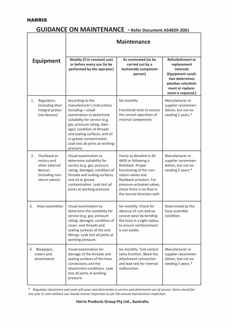
Equipment
Maintenance
Weekly (if in constant use) or before every use (to be
performed by the operator)
As nominated (to be carried out by a
technically competent person)
Refurbishment or replacement
intervals (Equipment condi-
tion determines whether refurbish-
ment or replace-ment is required.)
1. Regulators (including their integral protec-tive devices)
According to the manufacturer’s instructions including – visual examination to determine suitability for service (e.g. gas, pressure rating, dam-age); condition of threads and sealing surfaces; and oil or grease contamination. Leak test all joints at working pressure.
Six monthly:
Functional tests to ensure the correct operation of internal components
Manufacturer or supplier recommen-dation, but not ex-ceeding 5 years.*
2. Flashback ar-restors and other external devices (including non-return valves)
Visual examination to determine suitability for service (e.g. gas, pressure rating, damage); condition of threads and sealing surfaces; and oil or grease contamination. Leak test all joints at working pressure.
Yearly as detailed in AS 4603 or following a flashback. Proper functioning of the non-return valves and flashback arrestors. For pressure-activated valves, check there is no flow in the normal direction with
Manufacturer or supplier recommen-dation, but not ex-ceeding 5 years.*
3. Hose assemblies Visual examination to determine the suitability for service (e.g. gas, pressure rating, damage); condition of cover; and threads and sealing surfaces of the end fittings. Leak test all joints at working pressure.
Six monthly: Check for absence of cuts and ex-cessive wear by bending the hose in a tight radius, to ensure reinforcement is not visible.
Determined by the hose assembly condition.
4. Blowpipes, mixers and attachments
Visual examination for damage of the threads and sealing surfaces of the hose connections and the attachment conditions. Leak test all joints at working pressure.
Six monthly: Test control valve function. Blank the attachment connection and leak test for internal malfunction.
Manufacturer or supplier recommen-dation, but not ex-ceeding 5 years.*
* Regulator elastomers and seals will wear and deteriorate in service and deteriorate out of service. Items stored for one year or over without use should receive inspection as per the annual maintenance inspection.
GUIDANCE ON MAINTENANCE - Refer Document AS4839-2001

HARRIS
Harris Products Group Pty Ltd., Australia.
Oxy Acetylene Professional Equipment Part No. (6290)
Cutting Thickness
(mm)
Oxy Pres-sure
(KPA)
Fuel Pressure
(KPA)
000 00AC 0AC 1AC 2AC 3AC 4AC 5AC 6AC
0-5
5-10 10-15 15-25 25-30
50-100 100-175 175-200 250-300
100-200 100-200 150-250 200-350 300-450 300-450 300-550 300-550 300-550
40 40 40 40 40 40 40 40 40
TABLE 2 Tip Chart Pressure Guide
Oxy Acetylene Welding & Brazing Part No.
Size
Oxy Press. (KPA)
Fuel Press. (KPA)
Mixer
0090 23A9
0
1,3,5,6,8 1,3,5,6,8
50 50
50 50
E43, E43HC E43, E43HC
Oxy Acetylene Gouging Part No. (6290)
Cutting Thickness
(mm)
Oxy Press. (KPA)
Fuel Press. (KPA)
1G 2G 3G
3-6
5-10 6-13
250 350 350
40 40 40
Oxy Acetylene Heating Tip Part No.
Size
Oxy Press (KPA)
Fuel Press (KPA)
Mixer
J63 J63 J63 J63
J143
1 2 3 4 5
40 50
100 160 180
40 50 80
120 120
E43, E43HC E43, E43HC
E243 E243 E343
NOTE: For safety use large Bore 8mm or above with sizes 3, 4 and 5 tip. Size 3, 4 and 5 tips exceeds the capacity of one standard
Oxy Propane Torch Part No. (6290)
Cutting Thickness
(mm)
Oxy Press. (KPA)
Fuel Press. (KPA)
000NX 00NX 0NX 1NX 2NX 3NX 4NX 5NX 6NX
0-5
5-10 10-15 15-25 25-30 50-75
75-150 150-200 200-300
100-200 150-200 200-300 250-350 300-400 300-450 350-550 350-550 350-550
40 40 40 40 40 40 40 40 40
Oxy Propane Gouging Part No. (6290)
Cutting Thickness
(mm)
Oxy Press. (KPA)
Fuel Press. (KPA)
1GG 2GG 3GG
3-6
5-10 6-13
250 350 350
40 40 40
Note: The low fuel gas pressure is applicable when using Harris universal pressure mixing systems
Oxy Propane Specialty Tip Part No. (6290)
Cutting Thickness
(mm)
Oxy Press. (KPA)
Fuel Press. (KPA)
NFW
2NFFR
Rivet
Washing Rivet Cut-
ting
300 350
40 40
1.51.51.51.51.51.51.51.51.51.5
1.51.5
1.51.51.5

HARRIS
Harris Products Group Pty Ltd., Australia.
Oxy Propane Brazing Tip Part No.
Size Oxy Press.
(KPA) Fuel
Press. (KPA)
Mixer
0090
1390
2N,4N,6N,8N
3N,5N,6N,8N
100-210
100-210
40
40
Universal Pres-
sure Mixing
TIP CHART PRESSURE GUIDE—CONTINUED
Oxy Propane Heating Tip Part No.
Size Oxy Pressure
(KPA) Fuel Pres-
sure (KPA)
Max. MJ based on
Flow
1390 2290 2290 2290 2290 2290
H
1H 2H 3H 4H 5H
350
100-200 200-300 200-500 300-600 400-800
50 50 50
100 100
100-200
98 MJ/HR
186 MJ/HR 298 MJ/HR 532 MJ/HR 663 MJ/HR 934 MJ/HR
Note: All tables are for use as a guide only. Specifications may change with-out notice. Gas abbreviations are not exact technical terms.
Plate Thickness Tip Size Type Oxy Press. Acet Press.
1-6 6-10
12-20 25-75
100-25
6 8
12 15 20
41 41 41 41 41
200 200 250 350 400
40 40 40 40 40
3-6 6-12
12-20 25-75
100-125
6 8
12 15 20
44 44 44 44 44
200 200 250 400 400
40 40 40 40 40
Type 41 = Oxy Acetylene Type 44 = Oxy/LPG
1.5
1.5
HARRIS
Harris Products Group Pty Ltd., Australia.