instruction manual gilian” · l-8oo-7-on-site (l-800-766-7483) 689 north james road - columbus,...
TRANSCRIPT

Instruction Manualfor the
Gilian”
Primary Standard Airflow Calibratorwith Interchangeable Flow Cell Assemblies
Flow Cell Assembly RangesLow : 1 to 250 cc/min.
Standard : 20 cc/min. to 6 LPMHigh : 2 to 30 LPM
On-Site Instrumentsl-8OO-7-On-Site (l-800-766-7483)
689 North James Road - Columbus, Ohio 43219
Prologue
This Instruct ion Manual descr ibes the basic pr inciples, instal lat ion,operat ion/controls and maintenance for the Ci l ibrator, Pr imary StandardAirf low Cal ibrator manufactured by Ci l ian Instrument Corp.
Table of ContentsThe Gil ibrator
Section # Page #1 Introduct ion 2
2 General Description 2-6
3 Theory of Operation 7
4 Operating Procedures 8-12Initial Set-up & Operation
5 Storage E Maintenance 13-17
6 The Printer Module 1 8Introduction EGeneral Description 18-19Theory of Operation 1 9Operation Procedures 19-21Storage and Maintenance 21
7 Spec if icat ions -The Gil ibrator 22The Printer Module 23
8 Cilibrator Parts List 23
9 Warranty E Service Policy 24
1

Section 1Introductih
The Gil ibrator is a high accuracy, e lectronic bubble f lowmeter thatprovides instantaneous a i r f low readings and a cumulat ive averaging ofmult ip le samples. The Gi l ibrator system provides a large dynamic rangethrough the use of 3 interchangeable f low cel l assembl ies. A deletef u n c t i o n , o n t h e C o n t r o l U n i t , subtracts eroneous readings to insureaccurate data . The Control unit also supports a hard copy print out throughthe use of a pr inter accessory- .
S e c t i o n 2General Description (See fig. la)
The Gi l ibrator is comprised of the fol lowing basic components: FlowCell Assembly, Control Unit (base), Battery Charger and Soap Solution. Dif-ferent s ized inter -changeable F low Cel l Assembl ies are avai lable for use asfo l lows:
Low Flow : 1 to 250 cc/min.Standard Flow : 20 cclmin to 6 LPMHigh Flow : 2 to 30 LPM
In addit ion to the basic components, an opt ional Pr inter Module isavailable. The pr inter provides a hard copy record of cal ibrat ion data,however, identical data is displayed on the LCD of the Cil ibrator ControlUnit during cal ibrat ion.
1. Flow Cell Assembly (See fig. lb)The Flow Cel l Assembly consists of a Bubble Generator and Sensor
Block. Each Bubble Generator is s ized to produce a bubble f i lm stretchedacross the diameter of the f low cel l tube which is carr ied by a i r f low fromthe bottom to top of the tube. As the bubble t raverses past two inf raredsensors, each sensor t ransmits a s ignal to the Control Unit (base) indica-t ing the passage of the f i lm. The Flow Cell Assembly incorporates a manualbubble init iat ion push button which starts the f i lm on i ts travel up thetube.
A. Bubble Generator1) F low RangesLow Flow : 1 to 250 cclmin.Standard Flow : 20 cc/min to 6 LPM IHigh Flow : 2 to 30 LPM
2) Pulsat ion Damper (2) - a buil t - in damper smoothes out anypulsat ion’ within the air f low and reduces occi lat ion of the bubblef i lm assuring maximum accuracy.
3) Bubble Init iate Button (22) - This pushbutton lowers the BubbleG e n e r a t o r R i n g ( 2 1 ) i n t o t h e s o a p s o l u t i o n r e s e r v o i r . Uponreleasing the button, the r ing l i f ts out of the soap solution anda f i lm bubble is generated across the opening of the f low tube(241.
2

4) Bubble Breaker (4) - The Bubble Breaker is a secondary chamberin the upper chamber which provides the soap f i lm a rapid expan-sion path which is instrumental in breaking the bubble. ‘Thisprevents excessive wal l wet t ing by the soap f i lm and a l lows i t tof low back into the cel l .
5) Storage Tubing (25) - This anti -spi l l tubing connects upper andlower cel l chambers and prevents the soap solut ion f rom evapora-t ing which may cause the solut ion concentrat ion to change. ’
CAUTION: If transporting by plane, be sure to disconnect this hosing fromupper or lower Flow Cell Chamber Bosses (23 & 26) to prevent pressurizationand possible rupture within the Bubble Generator.
8. Sensor Block (8)Surrounding the f low tube (24),and secured between the upper andlower chamber of the bubble generator , is the Sensor Block (8) .The blockincorporates lower and upper sensors for t ime start andtime stop. Thesensors consist of an infrared emitter and detectorpairs whose sensi t iv i ty and accuracy is control led by a “columna-t i n g s l o t ” . T h i s b l o c k i s s e c u r e d t o t h e B u b b l e G e n e r a t o rAssembly (1) by means of two Locking Screws ( (7) and a l lows easyremoval to fac i l i ta te c leaning.
1) E lectr ica l In ter face - The Electr ica l In ter face provides powerto the sensing system as wel l as transmits t iming information tot h e C o n t r o l U n i t .
2. The Control Unit (base) (See f ig . la )The Control Unit (14) contains a crystal control led t iming system,
a micro processor control system, and an LCD readout for displayingflow and messages. The Control Unit a lso contains switches for Reset(17), Delete (16) and Auto-Averaging (15) funct ions as wel l as anPrinter Jack (18) interface port for direct connection to a hard copyprinter. LED indicators are provided to note Charging (11) and Runcal ibrat ion (20) operat ion.
a) Power (12) - switch turns the Control Units power on and off .
b) Charge Indicator LED (11) - lights when the charger is pluggedinto the Charging Jack
c) Printer Jack (18) - provides interface for auxi l lary pr inter .
d) Reset (17) - push button deletes al l current information forthemicro processor in order to in i t ia te a new sequence.
e) Delete (16) - push button automatical ly deletes false informa-tion from the average and will reset the average and sample numberto the previous reading. When a pr inter is in l ine, th is wi l li n d i c a t e a m i n u s s y m b o l a n d t h e a v e r a g e w i l l r e t u r n t o t h eprev ious va lue .
3
f) Average (15) - push button when pushed and held wi l l d isplaythe average of the previous sequence of readings. When re leasedwi l l d isplay the last actual reading and when re-pushed and held,w i l l show the numbe,r of samples in the sequence wi th d isplayinformation (S=sample #) . Releasing the button wi l l automatical -ly br ing the display back to the last reading.
g) Sequence Run Indicator LED (20) - indicates bubble sequence byl ight ing as the bubble passes between the two sensors. The LCD(19) wi l l be b lank. The Run signal wi l l a lso l ight when turningon the Control Unit and wi l l ext inguish after unit has f inishedi t ’s in i t ia l sequence check.
h) Low Battery - wi l l indicate on the LCD display (19) i f insuff i -c ient battery vol tage is avai lable to operate the uni t proper-ly. Since power for al l Control Unit functions is derived from therechargeable ‘NiCad battery, the batter ies must be ful ly chargedfor proper operation. A “Low Battery” indicat ion wi l l a lso appearini t ia l ly when turning the Control Unit ON as a sequence check ofthe uni t ’s e lectronics.
i) Cable Assembly (5) - mates with the Connecting Jack (6) in theback of the Sensor Block. I t provides power for the sensingsystem, i n f o r m a t i o n r e g a r d i n g c e l l s i z e , a n d c o n t r o l o f t h et iming information to the micro processor.
j) Timing System - The quartz control led t iming‘system controlsinfra-red sensor act ivat ion to assure maximum calculat ion accura-
CY.
k) Micro Processor - controls the t iming and mathematical dataprocessing to provide opt imum f low measurement character ist ics.This programmable micro processor can be upgraded as new programsbecome available.
3. Battery ChargerStandard wal l operated 120V charger to charge Gi l ibrator Control
Unit for 14 hours prior to operation. The Charging LED on the ControlUni t wi l l be i l luminated whi le ,charging is in progress.
4. Soap SolutionT h i s s p e c i a l l y c o m p o u n d e d l o w r e s i d u e s o a p i s s p e c i f i c a l l y
designed to provide high f i lm strength and compatibi l i ty with themater ia ls used within the Flow Cel l Assembly.

The Gilibrator SystemThe Gilibrator
Nomenclature
1 .2.
3.
::6.7.6.9.
1 0 .1 1 .1 2 .1 3 .1 4 .1 5 .1 6 .1 7 .1 6 .1 9 .20.21.22.2 3 .24.
Bubble Generator AssemblyD a m p e r P l a t e2a. Pulsation Damper2b. “0” RingSpacerPlate, Bubble BreakerCable AssemblySensor Block Connecting JackSensor Block Locking ScrewSensor Block
25.26.
Figure la

The Gil ibrator SystemThe Flow Cel l Assembly
Nomenclature II
Bubble Generator AssemblyDamper Plate2a. Pulsat ion Damper2b. “0” R i n gSpacerPlate , Bubble BreakerSensor Block Locking ScrewSensor BlockBase Plate Assembly9a. “0” R i n gBubble Generator RingBubble Init iate Button
21.22.23. Air Inlet Boss24. Flow Tube25. Storage Tubing26. Air Outlet Boss27. Safety Tape
1.2 .
3 .4 .7 .a .9.
a---
6
F i g u r e l b
w

S e c t i o n 3Theory of Operation
1. Pr imary Air f low StandardTo be a pr imary standard, a l l values must be absolute and measured as
absolute. A pr imary standard a i r f low measurement is a volume d iv ided by at ime interval as performed by the Control Unit of the Gil ibrator. T h evolume, V , is measured volume of space between two inf rared sensors. Thet ime is that interval needed for a soap f i lm bubble to t raverse between thetwo sensors which bound the volume. Therefore, V/t, the volume per unit oftime, becomes the airflow and is prime because all measurements are basic...vo lume and t ime. In today’s technology, t ime is measured by an electronicclock whose accuracy exceeds that of volume measurements by orders ofmagni tude, hence, the control accuracy volume resides sole ly wi th volumemeasurements.
2. Bubble Generat ion and measurementa) The Gi l ibrator consists of two elements, the Flow Cel l Assembly and
t h e C o n t r o l U n i t ( b a s e ) . The function of the Flow Cell Assembly -is togenerate a c lean consistent bubble which t raverses up the f low tube. Meas-urement of the t raverse t ime is done by infrared sensor pairs which aremounted at the bottom and the top of the Sensor Block. The volume bound bythese sensors is speci f ical ly adjusted to a volume standard by a l lowing theupper sensor blocks to move in unison so as to enable this cal ibrat ion to beset accurately to a pr imary volume standard, A second function of thesensor b lock provides the inter fac ing code to def ine the ce l l volume as wel las sensi t iv i ty adjustments for the opt ical sensor systems.
b) As the bubble t raverses between the sansors, f i rst one and then thesecond, sensors are tr ipped thereby providing the t ime for the bubblet raverse . This t iming information is sent to the micro processor of thecontrol base which in turn provides the crystal control t ime base for thesystem. The t iming information along with the volu,me information are thensent to the micro processor which in turn does the necessary mathematicalcalculat ions which al low the f low to be displayed direct ly on the LCDreadout. In order to insure the highest accuracy possible, a Delete andAverage funct ion are provided on the Control Unit . The Delete al lows forsubtracting out an obvious malformed bubble and the average allows the userto obtain average information without penci l or paper. A pr inter interfaceal lows connect ion of a Pr inter Module so that hard copy can be produced.

S e c t i o n 4Operating Procedures
1. Ini t ia l Set-upT h i s c o v e r s a l l s t e p s n e c e s s a r y t o b r i n g t h e G i l i b r a t o r i n t o
operat ing status. This includes charging, cel l mounting, instal l ingsoap solut ion, connecting the printer (optional) and connecting thesampl ing source.
A) Charging the Gil ibrator1. Pr ior to operat ion, plug the 120V charger into the wal l andconnect to the Charging Jack (13) on the r ight side of the ControlUnit . The unit ’s Charging LED (11) wil l l ight indicating that theunit is charging properly. Al low the battery system to charge for14 hours prior to operat ion.
B) Mount ing the Flow Cel l Assembly (See f ig . 2)1 . Select the Flow Cel l Assembly to cover the f low rangerequired.
2. The bottom of the Flow Cell Assembly employs a quick mountfeature. The base of the Flow Cel l Assembly is posit ioned ontothe mounting plate (10) of the Control Unit (14).
F i g u r e 2
Cel l Assembly(bottom)
-
M O ‘unting
Control Unit
J
late
a

3. Engage the pin of the cel l assembly base into the mountingplate of the Control Unit . When the Flow Cel l Assembly is properlyengaged, the base of the cel l wi l l be f lush to the mounting plateand the cel l assembly wi l l face towards e i ther the r ight or lef ts ide . (See f ig . 3 )
Figure 3
I II I
Flow Cel l Assembly-
I I
C o n t r o l U n i t /I
‘Mounti
Cel l Assembly Mounted
4. Grasp the bottom cel l chamber and rotate the cel l unt i l i tclicks in. CAUTION: Always engage E disengage the cell by graspingand rotating 09 the bottom cell chamber. The cell assembly willnow face forward. (see F ig . 4 )
Figure 4
Firmly twist cel l into the lockingposit ion
Flow Cel l Assembly
Control Unit

5 . Insert the Control Unit ’s Cable Assembly (5) into the SensorBlock Connect ing Jack (6) located on the back of the Sensor Block(8). (See f ig . 5 )
Figure 5
. . . . .0. . . .
Sensor BlockConnect ing Jack
Control Unit Connecting the Control Unit ’sInterface Plug Interface Plug to the Sensor Block’s
Connect ing Jack.
Cl Adding the Gil ibrator Soap Solution
1. Remove the Storage Tubing (25) from the upper Outlet Boss 26)o f t h e u p p e r c e l l . F i l l t h e d i s p e n s e r b o t t l e p r o v i d e d w i t hCil ibrator soap solution. Using the rubber Storage Tubing as afunnel , s lowly add soap solut ion from the dispenser.
2. The amount of soap needed is determined by depressing theB u b b l e I n i t i a t e B u t t o n ( 2 2 ) a n d h o l d i n g i t d o w n i n t h e l o w e rposit ion. Continue to add enough soap solution unti l the anglededge at the bottom of the Bubble Generator Ring (21) is immersedin the solution. Do Not Overfi l l ! (See f ig . 6 )
3. After f i l l ing is completed, the rubber Storage Tubing (25) maybe removed completely . Recap the soap dispenser bott le for lateruse. NOTE: If the Flow Cell Assembly is not going to be used fora prolonged period of time, reinstall the rubber Storage Tubingbetween the inlet and outlet bosses (23 t 26). This will p&ventevaporation from occurring which may cause the solution’s concen-trations to alter.
D) Printer Connect ion ( i f appl icable)
1. Connect pr inter cable to Printer Jack connector (18) on thel e f t s i d e o f t h e C o n t r o l U n i t . B e s u r e t o p r o p e r l y m a t c h u pconnectors before engaging.
1 0

BubbleInit iate
Bubble GelSolut ion Res
E) Connect the Sampler
1. Connect the air sampler to be cal ibrated to the Upper OutletBoss (26) of the Flow Cel l Assembly with l/4@’ ID tubing. NOTE: Anauxi l lary l iquid t rap between sampler and f low cel l is recommendedto prevent moisture carry over into the sampler during continuouscal ibrat ion per iods.
2 . Operation
A) Conditioning the Flow Tube
1. Turn on the sampler. Depress the Bubble Ini t iate Button (22)several t imes to wet the inner wal ls of the f low tube (24) . Youw i l l n o t b e a b l e t o i n i t i a t e a t i m i n g b u b b l e w i t h o u t f i r s t“Priming”the f l o w t u b e . T h e o p e r a t o r w i l l d e v e l o p a f e e l f o rbubble generat ion wi th pract ice .
B) Power Up
2. After the Flow Tube walls have been “primed”, turn on the PowerSwitch (12) of the Ci l ibrator Control Unit (base) and the PrinterModule i f one is being used. Wait approximately 10 seconds whilethe system runs through i t ’s check sequence. The Run LED (20)wi l l l ight at th is t ime as wel l as a Lo Battery indicat ion and aseries of f ive dashes displayed on the LCD Readout (19) . Do notoperate the Ci l ibrator unti l the Run LED signal ext inguishes.Ready operat ion is indicated by a ser ies of 4 dashes.
C) Bubble Generat ion
1. For optimum bubble generat ion, depress the Bubble Ini t iateButton (22) and hold to init iate 1 bubble up the f low tube. Re-lease the button to ini t iate a second bubble up the f low tube.This wi l l be the standard procedure to making clean, consistentbubbles at High and Medium f low ranges.
1 1

2. As the bubble r ises up the Flow Tube (24). i t wi l l in i t ia te at iming sequence when i t passes the lower sensor (Run LED wi l ll ight) and culminate the t iming sequence upon passing the uppersensors (Run LED wil l ext inguish) . The t iming information is thent r a n s m i t t e d t o t h e c o n t r o l u n i t w h i c h w i l l p e r f o r m a l l t h enecessary ca lculat ion. A f low reading wi l l instantaneously appearon the LCD display (19).
However, i f a bubble breaks before the t ime sequence iscompleted, t iming wi l l cont inue unt i l another bubble is generatedto tr ip the second sensors. This wi l l cause an erroneous readingand should be subtracted from the average by hit t ing the DeleteButton (16).
I f a Pr inter Module is used, be sure the pr inter has comple-Led i t ’s pr int ing sequence before pressing the Delete Button. Whenthe Delete Button is act ivated, a negat ive symbol wi l l be display-ed on the LCD of the Control Unit and the printer wil l init iatea’line showing this subtract ion.
D) Flow Readout
With Printer Option - The pr inter wi l l pr int in sequence the f low,average and sample number of each successive bubble reading.
Without Printer Option - The Control Unit wi l l display the actualflow for each sample and will accumulate and average each succes-s ive read ing .
1 . A v e r a g e ( 1 5 ) - In order to display average and number ofsamples, depress and hold the Average Button. Releasing thebutton wi l l display the last f low reading. Repressing the buttonwi l l d isplay the number of samples accumulated for that averagingsequence and re leasing wi l l once again d isplay the last f lowreading. A d d i t i o n a l p r e s s i n g a n d h o l d i n g w i l l r e p e a t t h i ssequence.
2 . De le te (16) - To delete obvious false readings, push the DeleteButton which wi l l automatical ly delete the false information fromthe average and reset the average and sample number back to theprevious reading.
3 . Reset (17) - To reinit iate the sequence for addit ional pumps,h i t t h e R e s e t B u t t o n . This wi l l zero out a l l sample and averageregisters within the Control Unit and wi l l cause the pr inter toindex oneline and reprint sequence headings. This denotes thestar t of a new sequence. The Reset Button is also used i f amalformed bubble is generated and has not been been subtractedfrom the average byuse of the Delete Function.
1 2

1. Storage
Sect ion 5Storage t Maintenance
A. Take DownTurn OFF the Control Unit , the sampler and the Printer Module[i f applicable) .
B. For Dai ly UseIf Cilibrator is to be used dai ly , i t is recommended that the air
sampler be removed and the Storage Tubing be replaced between the upperand lower ce l l chambers . Plug in the Charger and connect into theControl Unit Charging Jack (13). Recharge overnight for next dayusage.
C. Long Term StorageIf the Cil ibrator is not to be used for long periods of t ime, the
fol lowing steps should be taken to keep the unit in proper workingorder.
1. Disconnect the Cable Assembly from the back of the Sensor Blockon the Flow Cel l Assembly.
2. Remove the Flow Cel l Assembly from the Control Unit (base) .Remove the Cell from the base in the reverse order in which it wasmounted.
3. Pour soap solution out of the Bubble Generator through theLower In let Boss (23) By holding Bubble Generator horizontal ly andwith the inlet boss facing down, t i l t at a 45 degree angle. Con-t inue unti l a l l of soap solut ion has poured out. (See f ig. 7)
Figure 7
13

4. Flushing the Bubble Generator Clean - There are 2 methods inwhich to c leanse the Bubble Generator .
a. The unit may be flushed clean by connecting Storage Tubingto the Upper Outlet Boss and continuously running waterthrough the generator unt i l water runs clear . Maintain ahorizontal posi t ion with cel l bosses facing down and f lushf o r 1 5 - 3 0 s e c o n d s . T h e n r e m o v e t u b i n g a n d r o c k t h ecel l in a see-saw fashion to empty out a l l excess water .Replace Seal Tubing between the Upper and Lower Cell bosses.
Figure 8I~FIOW C e l l A s s e m b l y ;
F low Cel l Assembly
1 1 wate r c lea rs . 1 1
I
1(See f ig . 8 )
Rock the F low Cel l Assemblyin a see saw fashion.
o r ( s e e F i g u r e 9 )b. Remove the Sensor Block Assembly by loosening the 2holding screwsand sl iding the block out f rom between theUpper & lower cel l chambers. Remove Safety Tape. Using asmal l f la t b lade screw dr iver , l i f t off the Damper Plate (2)using the notch between the upper chamber and the l id.Remove the Spacer (3) and then the Bubble Breaker Plate (4) .This gives completeaccess to the inter ior of the Flow Cel lTube. Continue to run clear water through the cel l unti lwater runs c lear . Rock cel l to empty out a l l excess water .Replace the Bubble Breaker Plate (4) and center the AirOut let Boss (26) with the plates largest hole. Next insertthe spacer. To replace the Damper Plate assembly, moisten theO-ring (2b) with soap solut ion and then press the DamperPlate into the top of the Upper Cel l Chamber.Use f ingers andfirmly sqeeze plate into upper f low cel l chamber.
1 4

Figure 9
1 -Doer F l o w C e l l Chlamber 1
g-&J, Flush
Do Not exert your body weighton the Bubble Generator topress plate into place. Exces-sive weight on the flow cellmay result in breakage.Replace the Seal Tubing betweenthe Upper and Lower cell bossesfor storage.
r 1
Damper Plate #sembly
Upper Flow Cel l
L
hamber
Reposit ior!into Upperand press
Damper Plate AssemblyFlow Cel l Chamber
f irmly into place.
Bubble Generator Assembly
Screws
15
2. Maintenance
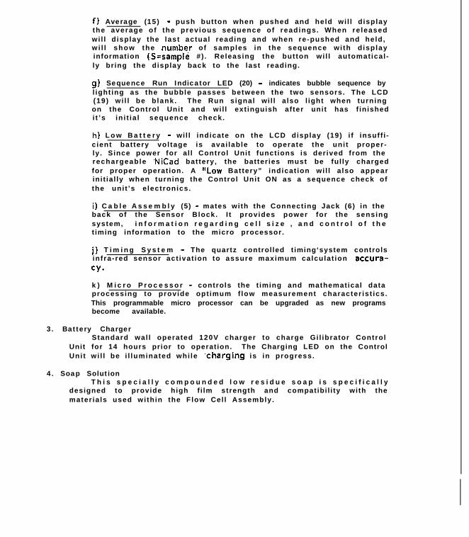
The Ci l ibrator is designed so that l i t t le maintenance is required. Thearea which may need replacement is the Damper Diaphragm assembly. I f thediaphragm becomes ruptured or worn please use the fol lowing procedure fori ts replacement.
a . Removing and Replacing Damper Plate Diaphragm
First , remove f lexible Safety Tape (27) from around the l ip of theDamper Plate assembly. 1) Using a small flat blade screwdriver, removethe Damper Plate (2) from the Upper Cel l Chamber using the notchprovided. Remove the large O-r ing (2b) and the Pulsat ion Damperdiaphragm (2aI. (See f ig . 10)
CA\Damper Plate Assembly
Figure 11
[A!r F low Cel l Chamber
Insert a Fiathead Screwdriverbetween the Damper Plate Assembly
the Iip of the Upper Flow Cella m b e r . Gently pry apart the twotwisting the screwdriver.
b-4F i g u r e 1 0
Bubble Generator Assembly
Qf30Damper Plate
2) To replace, center new diaphragm over Damper Plate aperture andr o l l O - r i n g o v e r d i a p h r a g m a n d i n t o t h e O - r i n g g r o o v e . I fwr ink les occur , repeat the procedure to achieve a smooth p lace-ment . (See f ig . 11)
16

Damper Plate Asss
Upper Flow Cel l Ch
Reposit ion Damper Plate Assemblyinto Upper Flow Cel l Chamber
bly-
lber -
Figure 12
Bubble Generator Assembly
.
3) Wet 1@088-ring of Damper Plate & press into the Upper Cel lChamber f i rmly. (see Fig. 12)
4) Replace Safety Tape around l ip of plate and the upper f lowcel l chamber .
b . Leakage Check - The system should be leak checked at 6” H20 byconnect ing a manometer to the out let boss and evacuate the in lett o 6” H 2 0 . No leakage should be observed.
c. Cleaning - To clean the exter ior of the Bubble Generator use amild detergent and warm water. NEVER USE ALCOHOL, ACETONE OR ANYOTHER HARSH CLEANERS TO CLEAN THE BUBBLE GENERATOR.
d . T r a n s p o r t a t i o n - W h e n t r a n s p o r t i n g t h e G i l i b r a t o r , e s p e c i a l l yby air , i t is important that one side of the seal tube whichconnects the in let and out let boss, be removed thereby a l lowing f o requal iz ing internal pressure within the generator . D o N o t t r a n s p o r tunit with soap solut ion or storage tubing in place.
CAUTION: Do Not Pressurize the Flow Cel l ! Excess ive pressure maycause cel l to rupture result ing in personal injury.
1 7
S e c t i o n 6Printer Module Operation
Part # C-800274
1. Introduct ionThe Ci l ibrator Pr inter provides a hardcopy record of a l l cal ibrat ion
data, identical to data calculated and displayed on the LCD readout of theGil ibrator Control Unit (base).
Handling Precautionsa. Do not use where the temperature is extremely hot or cold.b. Do not leave in direct sunl ight or where i t is dusty.c . Do not operate near l iquids or beverage.d. Do not operate without the heat sensit ive rol l paper loaded.e. Use only speci f ied Ci l ian Replacement Rol l Paper (A-400681) .f . Do not attempt to disassemble the unit .
NOTE: The printer should 0% be used with the Ci l ian InterconnectCable providedwhich suppl ies the *power for the pr inter . Use of th isprinter with any other cable may cause permanent damage to the pr interand to the equipment from which the cable is connected.The use of a non-shielded interface cable with the printer is prohibit -ed.
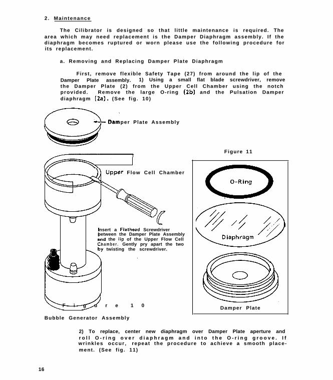
2 . General Descr ipt ion (See f ig . 13)The Printer is comprised of the fol lowing basic components: The Printer
Module (l), Interconnect Cable (2) and the Thermal Rol l Paper. A br iefdescript ion is provided of their use and operat ion.
The Gil ibrator SystemThe Printer Module Assembly
Nomenclature
1. Pr inter Module2. Pr inter Interconnect Cable3. Thermal Paper Cover4. Paper Cutter5 . Paper Feed6. Power (On-Off)7 . Paral le l Interface Connect0
1 8

a) Printer Module
1 .Power (6) - This switch act ivates operat ion of the pr inter f romthe Control Unit ’s power source.a heading l ine upon act ivat ion.
The printer wi l l ini t ial ly print
2.Paper Feed (5 )continuously.
- This switch is used to feed the Thermal PaperPress i t l ight ly. Note:
to feed out the paper.Use the Paper Feed switch
If paper is pulled out by hand, alwaysfeed it one l ine with the Paper Feed Swi tch before startingprinting.
3.Paper C u t t e r ( 4 ) - This is used to tear of the paper. Tear offby pull ing i t in the arrow direction only.
b) Thermal Paper -printer head.
A special ly t reated paper which is act ivated by the
.c) Interconnect Cable (2) - The interconnect cable provides e lectr ica lconnection between the printer (1) and the Gi l ibrator Control Unit(14).unit.
The pr inter operates from the same power source as the control
3. Theory of OperationThe Printer Module is powered and interfaced to the Control Unit
pf the Ci l ibrator by means of an Interconnect Cable. During a testser ies, the Control Unit t ransfers the sum of calculat ions of a givencalibration bubble and provides the flow rate, the sample number and anaverage of the successive f low rates determined in that ca l ibrat ionser ies .
The buttons on the Control Unit are used in conjunction with thePrinter module during calculat ion. Delete , Auto Average and Resetbuttons are provided to subtract fa lse readings and to ini t iate newcal ibrat ion sequences.
Calculat ions are automatical ly provided by the Control Unit andt r a n s f e r r e d t o t h e p r i n t e r f o r a h a r d c o p y r e a d o u t . T h i s i s p r i n t e donto a thermal sensi t ive ro l l paper which advances a s ingle l ine a f terpr int ing out each successive reading.retained for cal ibrat ion records.
These hard copy calculat ions are
4. Operat ion Proceduresa) Ini t ial set-up
1 .Connect ing the Printera) While the Gil ibrator Control Unit is in the OFF mode,connect the large end of the Interconnect Cable (2) to theP r i n t e r M o d u l e s P a r r a l l e l I n t e r f a c e C o n n e c t o r a n d s n a ph o l d i n g c l i p s i n p l a c e . C o n n e c t t h e s m a l l e r e n d t o t h eControl Unit ’s Printer connect port . Power is supplied to theprinter from the Control Unit ’s battery system.
2. Turn ON the Control Unit and the Printer Module.
1 9

1 Remove the heat sensit ive rol l paper cover.
2) Cut the end of the heat sensitive paper ashown below.
n n
3. Ins ta l l i ng theThermal Paper (See fig. 14)
a . SI ide back and removethe Thermal Paper Cover( 3 ) f r o m t h e p r i n t e rsect ion. (see F ig . 14)
b . Use the specia l Cilianheat sensi t ive ro l l paper(A-400681).
c. Cut the end of thepaper in a hal f c i rc le ortr iangular shape.
d. While insert ing the endo f t h e p a p e r , p r e s s t h eP a p e r F e e d S w i t c h ( 5 )u n t i l t h e p a p e r i s f e do u t . Replace protect ivepaper cover . (see F ig . 15 )
Figure 14
(3) While inserting the end of the tieat sensitiveroll paper in the direction of the arrow, pressand hold the paper feed switch until the paperis fed out. Since the outside of the heat rensi-tive roll paper is coated with a heat sensitiveagent,‘pay careful attention to the front andback of the paper.
Figure 15

b) Operation1. Star t Sequence
a. Turn the Control Unit ON. The Printer Module wil l printout an identi f icat ion heading for the current cal ibrat iontest . The program version is indicated after the identifica-t ion l ine for future reference. See sample below.
b. Initiate a bubble up the Flow Tube:and observe the readingon the Control unit and also on the Printer Module. T h ePr inter wi l l pr int in sequence the f low, average and samplenumber a f ter each successive reading.
NOTE : If you do not need a hard copy printout from the Printer Module, turni t O F F . T h i s w i l l p r e s e r v e t h e b a t t e r y l i f e o f t h e G i l i b r a t o r a s t h epr inter is powered by same.
2. The Average, Reset and Delete buttons on the Control Unit areused in conjunction with the printer during cal ibrat ion. They areas follows:a ) Average - In order to display average and number of samples,depress and hold average button. Releasing the button wi l ldisplay the last reading. Repressing wi l l d isplay the number ofsamples accumulated for that averaging sequence. Releasing thebutton wi l l once again display the last f low reading. Addit ionalpressing and holding wi l l repeat th is sequence.
b . Reset - To reini t iate the sequence for addit ional pumps,hitthe Reset Button. This wi l l zero out sample and average regis-ters within the Control Unit and wi l l cause the pr inter to indexone l ine and reprint headings. This denotes the start of a newsequence. The Reset Button may also be used if a malformed bubbleis generated and has not been been subtracted from the average byuse of the Delete Function.
c.Delete - To delete obvious fa lse readings, press the DeleteButton and subtract the false reading from the average. Thisresets the average and sample number back to the previous reading.
5 . Storage E Maintenancea) Storage (Dai ly Take Down)
1. Turn the Power of the Printer Module OFF. Al l data stored inthe pr inter cannot be reviewed once th is is done.2. Turn off the Power of the Control Unit.3 . Turn off the Power of the Sampler being cal ibrated.
b) Storage (Long Term) - I f the Printer Module is not to be used forlong periods of t ime, the fol lowing steps should be taken to keep theunit in proper working order.
1. Disconnect the interconnect cable from the Control Unit andfrom the Printer Module.2 . Store in or ig inal packaging or carry ing case.
c) Cleaning - Use a damp cloth with warm water. Never use ALCOHOL,ACETONE or any other harsh cleaners.
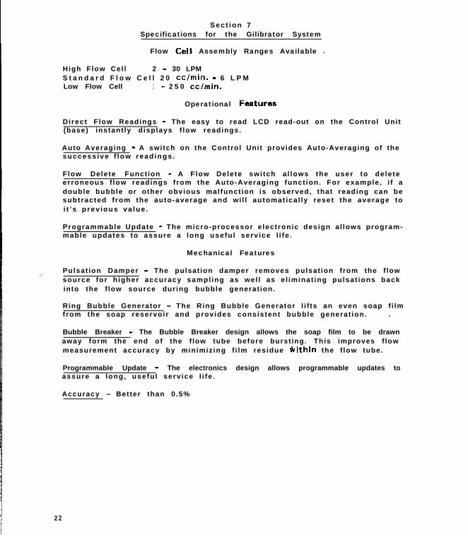
S e c t i o n 7Specifications for the Gilibrator System
Flow CelC Assembly Ranges Available 1
High Flow Cel l 2 - 30 LPMS t a n d a r d F l o w C e l l 2 0 cclmin. - 6 L P MLow Flow Cell 1 - 2 5 0 cc/min.
Operational Features
Direct F low Readings - The easy to read LCD read-out on the Control Unit(base) instant ly displays f low readings.
Auto Averaging - A switch on the Control Unit provides Auto-Averaging of thesuccess ive f low read ings .
Flow Delete Funct ion - A Flow Delete swi tch a l lows the user to deleteerroneous f low readings from the Auto-Averaging funct ion. For example, i f adouble bubble or other obvious malfunct ion is observed, that reading can besubtracted f rom the auto-average and wi l l automat ical ly reset the average toi t ’s prev ious va lue .
Programmable Update - The micro-processor e lectronic design al lows program-mable updates to assure a long useful serv ice l i fe .
Mechanical Features
i Pulsat ion Damper - The pulsat ion damper removes pulsat ion from the f lowsource for h igher accuracy sampl ing as wel l as e l iminat ing pulsat ions backinto the f low source during bubble generat ion.
Ring Bubble Generator - The Ring Bubble Generator l i f ts an even soap f i lmfrom the soap reservoir and provides consistent bubble generat ion. .
Bubble Breaker - The Bubble Breaker design allows the soap film to be drawnaway form the end of the f low tube before burst ing. This improves f lowmeasurement accuracy by minimizing f i lm residue Svithin the f low tube.
Programmable Update - The electronics design allows programmable updates toassure a long, usefu l serv ice l i fe .
Accuracy - Better than 0.5%
2 2
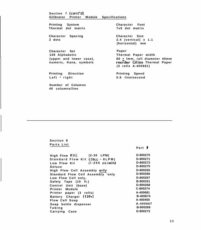
Sect ion 7 (cont’d)Gilibrator Printer Module Specifications
Printing SystemThermal dot matrix
Character Spacing2 dots
Character Font7x5 dot matr ix
Character Size2 .4 (ver t ica l ) x 1 .1(horizontal) mm
Character Set159 Alphabet ic(upper and lower case) ,numeric, Kana, symbols
PaperThermal Paper width80 + lmm, ro l l d iameter 40mmreo;der Cilian Thermal Paper(3 ro l ls A-400681)
Printing DirectionL e f t - r i g h t
Number of Columns40 columns/ l ine
Printing Speed0.6 l ine /second
S e c t i o n 8Parts List
High Flow Kit( (2 -30 LPM) D-800270S t a n d a r d F l o w K i t (2Occ - 6 L P M ) D-800271Low F low Ki t ( l - 2 5 0 cclmin) D-800272Deluxe D-800275High Flow Cel l Assembly only D-800265Standard Flow Cel l Assembly ‘only D-800266Low Flow Cel l only, D-800267Safety Tape (10 ft . ) B-800331Control Unit (base) D-800268Printer Module C-800274Printer paper (3 ro l ls) A-400681Battery Charger (120~) B-400674Flow Ce l l Soap A-400450
Soap bott le dispenser A-400667T u b i n g B-800269Carrying Case D-800273
Part #
2 3

S e c t i o n 9Warranty
The Seller warrants to the Purchaser that any equipment manufactured byi t and bear ing i ts nameplate to be free from defects in mater ia l or workman-ship , under proper and normal use and serv ice as fo l lows: If , at any t imewithin 90 days from the date of sale , the Purchaser not i f ies the Sel ler thatin his opinion the equipment is defect ive, and returns the equipment to theSel ler ’s or iginat ing factory prepaid, and the Sel ler ’s inspect ion f inds theequipment to be defect ive in mater ia l or workmanship, the Sel ler wi l lpromptly correct i t by either, at i ts option, repair ing any defect ive partor mater ia l or replacing i t f ree of charge and returned shipped lowest costtransportat ion prepaid ( i f Purchaser requests premium transportat ion,P u r c h a s e r w i l l b e b i l l e d f o r d i f f e r e n c e i n t r a n s p o r t a t i o n c o s t s ) . I fi n s p e c t i o n b y t h e S e l l e r d o e s n o t d i s c l o s e a n y d e f e c t i n m a t e r i a l o rworkmanship, the Sel ler ’s regular charges wi l l apply . This warranty shal lbe ef fect ive only i f insta l lat ion and maintenance is in accordance with ourinstruct ions and wri t ten not ice of a defect is given to the sel ler wi thins u c h p e r i o d . T h i s w a r r a n t y i s e x c l u s i v e a n d i s i n l i e u o f a n y o t h e rw a r r a n t i e s , w r i t t e n , oral or impl ied; specif ical ly , without l imitat ion,there is no warranty of merchantabil i ty or f i tness for any purpose. Thel iabi l i ty of the Sel ler shal l be l imited to the repair or replacement ofmater ia ls or parts as above set for th .
Limitat’ ion of Liabil i ty
T h e S e l l e r s h a l l n o t b e l i a b l e f o r a n y c l a i m f o r c o n s e q u e n t i a l o rspecia l loss or damage ar is ing or a l leged to have ar isen f rom any delay indel ivery or malfunct ion or fai lure of the equipment. The Sel ler ’s l iabi l i tyfor any other loss or damage ar ising out of or connected with the manufac-ture, sale or use of the equipment sold, including damage due to negl igence,shal l not in any event exceed the pr ice of the equipment suppl ied by us.
Serv ice Po l i cy
F o r a m i n i m u m f e e o f $95.00, Gilian Instrument Corp. wi l l overhaul ,repair and/or replace minor components, and recal ibrate one Ci l ibrator .Gilian reserves the r ight to proceed with addi t ional repairs up to a maximumc o s t o f $13O.CtO p e r G i l i b r a t o r w i t h o u t n o t i f y i n g t h e c u s t o m e r . I f majorcomponents must be replaced, Gilian wi l l not i fy the customer before proceed-ing wi th repairs .
When the instrument(s) is returned, please include a purchase ordermarked “Repair Cost not to Exceed $100. Without Customer Authorizat ion”.Also include company name, return shipping address, contact name and phonenumber, ser ial number(s) of cal ibrators, date of purchase and descript ion ofproblem. Return to:
Gilian Instrument Corp.35 Fairfield PlaceW. Caldwell, NJ 07006-6206Att: Gilibrator Repairs Dept.
2 4