instruction manual for arc welding machine · · 2014-07-04three phase static...
TRANSCRIPT

8
IMPORTANT: BEFORE STARTING THE EQUIPMENT,READ THE CONTENTS OF THIS MANUAL, WHICH MUSTBE STORED IN A PLACE FAMILIAR TO ALL USERS FORTHE ENTIRE OPERATIVE LIFE-SPAN OF THE MACHINE.THIS EQUIPMENT MUST BE USED SOLELY FOR WELD-ING OPERATIONS.
1 SAFETY PRECAUTIONS
WELDING AND ARC CUTTING CAN BEHARMFUL TO YOURSELF AND OTHERS.The user must therefore be educated
against the hazards, summarized below, deriving from weld-ing operations. For more detailed information, order themanual code 3.300.758
ELECTRIC SHOCK - May be fatal.· Install and earth the welding machine according tothe applicable regulations.· Do not touch live electrical parts or electrodes with
bare skin, gloves or wet clothing.· Isolate yourselves from both the earth and the workpiece.· Make sure your working position is safe.
FUMES AND GASES - May be hazardous to your health.· Keep your head away from fumes.· Work in the presence of adequate ventilation, anduse ventilators around the arc to prevent gases from
forming in the work area.
ARC RAYS - May injure the eyes and burn the skin.· Protect your eyes with welding masks fitted with fil-tered lenses, and protect your body with appropriatesafety garments.
· Protect others by installing adequate shields or curtains.
RISK OF FIRE AND BURNS· Sparks (sprays) may cause fires and burn the skin;you should therefore make sure there are no flam-mable materials in the area, and wear appropriate
protective garments.
NOISEThis machine does not directly produce noiseexceeding 80dB. The plasma cutting/welding proce-dure may produce noise levels beyond said limit;
users must therefore implement all precautions required bylaw.
PACEMAKERS· The magnetic fields created by high currents may affect theoperation of pacemakers. Wearers of vital electronic equip-ment (pacemakers) should consult their physician beforebeginning any arc welding, cutting, gouging or spot weldingoperations.
EXPLOSIONS· Do not weld in the vicinity of containers under pres-sure, or in the presence of explosive dust, gases orfumes. · All cylinders and pressure regulators used in
welding operations should be handled with care.
ELECTROMAGNETIC COMPATIBILITY This machine is manufactured in compliance with theinstructions contained in the harmonized standardEN50199, and must be used solely for professional purpos-es in an industrial environment. There may be potential diffi-culties in ensuring electromagnetic compatibility in non-industrial environments.
IN CASE OF MALFUNCTIONS, REQUEST ASSISTANCEFROM QUALIFIED PERSONNEL.
2 GENERAL DESCRIPTIONS
2.1 SPECIFICATIONS
This welding machine is a constant current power sourcebuilt using INVERTER technology, designed to weld coveredelectrodes (not including cellulosic) and for TIG procedures,with contact starting and high frequency.IT MUST NOT BE USED TO DEFROST PIPES.
2.2 EXPLANATION OF THE TECHNICAL SPECIFI-CATIONS LISTED ON THE MACHINE PLATE.
N°. Serial number, which must be indicated on any type of request regarding the welding machine. Three phase static transformer-rectifier frequency converter.Drooping-characteristic.
MMA Suitable for welding with covered electrodes.TIG Suitable for TIG welding.U0. Secondary open-circuit voltage X. Duty cycle percentage. % of 10 minutes during
which the welding machine may run at a certain current without overheating.
I2. Welding currentU2. Secondary voltage with current I2U1. Rated supply voltage
The machine has an automatic supply voltage selector.
3~ 50/60Hz 50- or 60-Hz three-phase power supplyI1 max. This is the maximum value of the absorbed current.I1 eff. This is the maximum value of the actual current
absorbed, considering the duty cycle.IP23C Protection grade of the housing, approving the
equipment as suitable for use outdoors in the rain.C: The additional letter C means that the equipmentis protected against access to the live parts of the power circuit by a tool (diameter 2.5 mm ).Suitable for hazardous environments.
NOTES: The welding machine has also been designed for use in environments with a pollution rating of 3. (See IEC 664).
2.3 DESCRIPTION OF PROTECTIVE DEVICES
2.3.1. Thermal protectionThis machine is protected by a temperature probe, whichprevents the machine from operating if the allowable tem-peratures are exceeded. Under these conditions the fankeeps running and the LED M lights.
S
3
IINNSSTTRRUUCCTTIIOONN MMAANNUUAALL FFOORR AARRCC WWEELLDDIINNGG MMAACCHHIINNEE
9
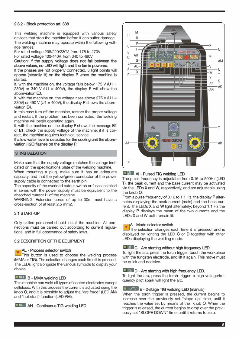
2.3.2 - Block protection art. 338
This welding machine is equipped with various safetydevices that stop the machine before it can suffer damage.The welding machine may operate within the following volt-age ranges: For rated voltage 208/220/230V, from 175 to 270VFor rated voltage 400/440V, from 340 to 490VCaution: if the supply voltage does not fall between theabove values, no LED will light and the fan is powered.If the phases are not properly connected, 3 light points willappear (steadily lit) on the display P when the machine isstarted.If, with the machine on, the voltage falls below 175 V (U1 =230V) or 340 V (U1 = 400V), the display P will show theabbreviation E3.If, with the machine on, the voltage rises above 275 V (U1 =230V) or 490 V (U1 = 400V), the display P shows the abbre-viation E4.In this case turn off the machine, restore the proper voltageand restart. If the problem has been corrected, the weldingmachine will begin operating again.If, with the machine on, the display P shows the message E2or E1, check the supply voltage of the machine; if it is cor-rect, the machine requires technical service.If a low water level is detected for the cooling unit the abbre-viation H2O flashes on the display P.
3 INSTALLATION
Make sure that the supply voltage matches the voltage indi-cated on the specifications plate of the welding machine.When mounting a plug, make sure it has an adequatecapacity, and that the yellow/green conductor of the powersupply cable is connected to the earth pin.The capacity of the overload cutout switch or fuses installedin series with the power supply must be equivalent to theabsorbed current I1 of the machine.WARNING! Extension cords of up to 30m must have across-section of at least 2.5 mm2.
3.1 START-UUP
Only skilled personnel should install the machine. All con-nections must be carried out according to current regula-tions, and in full observance of safety laws.
3.2 DESCRIPTION OF THE EQUIPMENT
AL - Process selector switch This button is used to choose the welding process
(MMA or TIG). The selection changes each time it is pressed.The LEDs light alongside the various symbols to display yourchoice.
B - MMA welding LED This machine can weld all types of coated electrodes exceptcellulosic. With this process the current is adjusted using theknob O, and it is possible to adjust the "arc force" (LED AN)and "hot start" function (LED AM).
AH - Continuous TIG welding LED
AI - Pulsed TIG welding LED The pulse frequency is adjustable from 0.16 to 500Hz (LEDT), the peak current and the base current may be activatedvia the LEDs X and W, respectively, and are adjustable usingthe knob O.From a pulse frequency of 0.16 to 1.1 Hz, the display P alter-nates displaying the peak current (main) and the base cur-rent. The LEDs X and W light alternately; beyond 1.1 Hz thedisplay P displays the mean of the two currents and theLEDs X and W both remain lit.
A - Mode selector switchThe selection changes each time it is pressed, and is
displayed by lighting the LED C or D together with otherLEDs displaying the welding mode.
C - Arc starting without high frequency LED.To light the arc, press the torch trigger, touch the workpiecewith the tungsten electrode, and lift it again. This move mustbe quick and decisive.
D - Arc starting with high frequency LED.To light the arc, press the torch trigger: a high voltage/fre-quency pilot spark will light the arc.
E - 2-sstage TIG welding LED (manual)When the torch trigger is pressed, the current begins toincrease over the previously set "slope up" time, until itreaches the value set by means of the knob O. When thetrigger is released, the current begins to drop over the previ-ously set "SLOPE DOWN" time, until it returns to zero.
®
MMA
TIG
TIG
MEM
MEM +
A V
AHG
AL
Q
AI
LA
R
AA
Z
B
V
W
X
AP
AN
N
P
AM
U
T
S
AO
Y
AB
OC
HI
FE
D
M

10
In this position, you may connect the pedal control acces-sory ART. 193.
F - 4-sstage TIG welding LED (automatic)This program differs from the previous one in that the arc isboth started and shut off by pressing and releasing the torchtrigger.
G - four-sstage TIG welding LED with dual currentlevel, (automatic).Set the two current levels before lighting the arc:First level: press the R key until the LED X lights, and adjustthe main current using the knob O.Second level: press the R key until the LED W lights, andadjust the main current using the knob O. When the torch trigger is pressed, the current begins toincrease over the previously set "slope up" time (led S lit),until it reaches the value set by means of the knob O. TheLED X lights and appears on the display P.Should it be necessary to reduce the current during welding,without shutting of the arc (for instance when changing thewelding material or working position, moving from horizontalto upright, etc.…), press and immediately release the torchtrigger: the current will switch to the second value selected,the LED W will light and X will go off.To return to the previous main current, press and release thetorch trigger once again. The LED X will light, and the LED Wwill go off. To stop welding at any time, simply hold down thetorch trigger for more than 0.7 seconds, then release. Thecurrent begins to fall to zero within the previously set "slopedown" time interval (LED U lit).If you press and immediately release the torch trigger duringthe "slope down" phase, you will return to "slope up" if it is setto greater than zero, or to the lesser current value of those set.NOTE: The expression "PRESS AND IMMEDIATELYRELEASE" refers to a maximum time of 0.5 seconds.
H - four-sstage TIG welding LED with three levelsof current (automatic).To set the three minimum welding currents, proceed as fol-lows:Press the selector switch R until the LED X lights, then adjustthe maximum current value using the knob O.Press the selector switch R until the LED W lights, thenadjust the intermediate current value using the knob O.Press the selector switch R until the LED AP lights, thenadjust the starting current value using the knob O.The operating logic is the same as previously described forwelding with dual current level (LED G).
I - special program LED To light the arc, press the torch trigger and hold it down; thecurrent begins to increase at a fixed rate. If the torch triggeris released, the current immediately rises to the weldingvalue (LED X). To stop welding, press the torch trigger andhold it down; the current begins to drop at a fixed rate. Thecurrent immediately returns to zero if the trigger is released.
L - spot-wwelding LED (Manual).After selecting the welding current (LED X) and the spotwelding time (LED T) using the selector switch R, set the val-ues using the knob O.This welding mode is to be used only if start-up with high fre-
quency is selected (LED D lit). In this welding mode, theoperator presses the torch trigger, the arc lights, and afterthe set spot welding time the arc shuts off automatically. Todo the next spot, you must therefore release the torch trig-ger and press it again.
M - LED - THERMAL PROTECTIONLights when the operator exceeds the duty cycle or per-centage intermittence admissible for the machine, andsimultaneously blocks the current output.NOTE: In this condition the fan continues cooling the powersource.
O - Knob Normally adjusts the welding current.Also, if you select a function with the selector switch
R, this knob adjusts its size.
P - Display Displays the welding current and the settingsselected by means of the push-button R and
adjusted via the knob O.In the machine blocking procedures (see 2.3.2), it displays:Three flashing or steadily lit pointsThe abbreviations E1 E2 E3 E4The abbreviation H20
N - Display Normally displays the arc voltage in relation tothe current welding process.
When setting the cooling unit operation, it displays the sta-tus of the unit.
Q - SELECTOR Selects and saves programs.The welding machine can save nine welding pro-
grams P01…..P09, and call them up using this button. Aworking program PL is also available. SelectingWhen this push-button is pressed briefly, the display Pshows the next program number after the one being workedon. If it has not been saved the message will flash, otherwiseit will remain steady.SavingOnce the program has been selected, hold for more than 3seconds to save the data. In confirmation, the program num-ber on the display P will stop flashing
R - SELECTOR When this button is pressed, the LEDs light in suc-cession:
Warning: only those LEDs that refer to the chosen weldingmode will light; i.e., in continuous TIG welding the LED T,representing the pulse frequency, will not light.Each LED indicates the parameter that may be adjusted bymeans of the knob O while the LED itself is lit. Five secondsafter the last variation, the LED involved will shut off; themain welding current will be displayed, and the correspond-ing LED X lights.
AO - Pre-ggas LEDAdjustment 0.05-2.5 seconds. Gasoutput time before starting welding.
MEM
MEM +
V
A
11
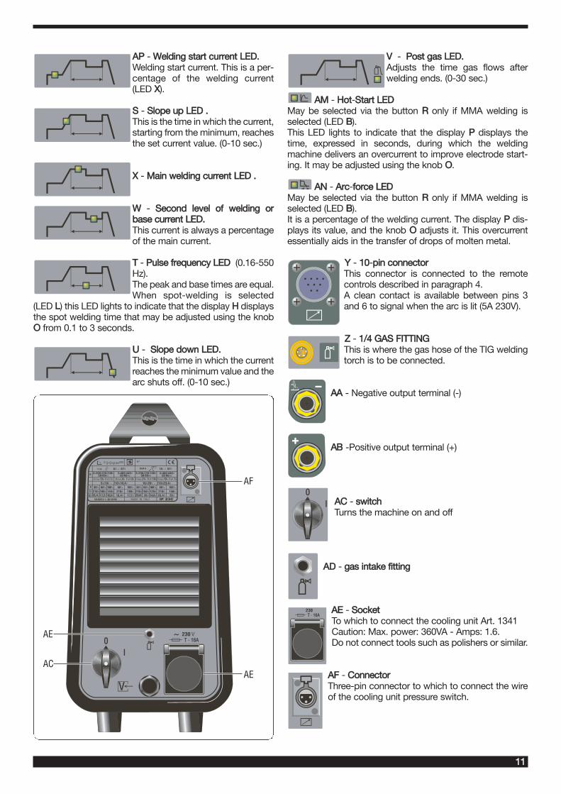
AP - Welding start current LED.Welding start current. This is a per-centage of the welding current(LED X).
S - Slope up LED .This is the time in which the current,starting from the minimum, reachesthe set current value. (0-10 sec.)
X - Main welding current LED .
W - Second level of welding orbase current LED. This current is always a percentageof the main current.
T - Pulse frequency LED (0.16-550Hz). The peak and base times are equal.When spot-welding is selected
(LED L) this LED lights to indicate that the display H displaysthe spot welding time that may be adjusted using the knobO from 0.1 to 3 seconds.
U - Slope down LED.This is the time in which the currentreaches the minimum value and thearc shuts off. (0-10 sec.)
V - Post gas LED.Adjusts the time gas flows afterwelding ends. (0-30 sec.)
AM - Hot-SStart LED May be selected via the button R only if MMA welding isselected (LED B).This LED lights to indicate that the display P displays thetime, expressed in seconds, during which the weldingmachine delivers an overcurrent to improve electrode start-ing. It may be adjusted using the knob O.
AN - Arc-fforce LEDMay be selected via the button R only if MMA welding isselected (LED B).It is a percentage of the welding current. The display P dis-plays its value, and the knob O adjusts it. This overcurrentessentially aids in the transfer of drops of molten metal.
Y - 10-ppin connectorThis connector is connected to the remotecontrols described in paragraph 4.A clean contact is available between pins 3and 6 to signal when the arc is lit (5A 230V).
Z - 1/4 GAS FITTINGThis is where the gas hose of the TIG weldingtorch is to be connected.
AA - Negative output terminal (-)
AB -Positive output terminal (+)
AC - switchTurns the machine on and off
AD - gas intake fitting
AE - Socket To which to connect the cooling unit Art. 1341 Caution: Max. power: 360VA - Amps: 1.6. Do not connect tools such as polishers or similar.
AF - Connector Three-pin connector to which to connect the wireof the cooling unit pressure switch.
TT - 1166AA
0I
0 pannello
V
00II
TT - 1166AA
AF
AE
AE
AC

12
3.3. GENERAL NOTES
Before using this welding machine, carefully read the stan-dards CEI 26/9 - CENELEC HD 407 and CEI 26.11 - CEN-ELEC HD 433. Also make sure the insulation of the cables,electrode clamps, sockets and plugs are intact, and that thesize and length of the welding cables are compatible with thecurrent used.
3.4 MMA WELDING (MANUAL METAL ARC)
- This welding machine is suitable for welding all types ofelectrodes, with the exception of cellulosic (AWS 6010)*.- Make sure that the switch AC is in position 0, then connectthe welding cables, observing the polarity required by themanufacturer of the electrodes you will be using; also con-nect the clamp of the ground cable to the workpiece, asclose to the weld as possible, making sure that there is goodelectrical contact. - Do NOT touch the torch or electrode clamp simultaneous-ly with the earth clamp.- Turn the machine on using the switch AC.- Select the MMA procedure by pressing the button A:LED B lit.- Adjust the current based on the diameter of the electrode,the welding position and the type of joint to be made.- Always remember to shut off the machine and remove theelectrode from the clamp after welding. If you wish to adjust the Hot-start (LED AM) and Arc forcefunctions (LED AN), see the previous paragraph.
3.5 TIG WELDING
This welding machine is suitable for welding stainless steel,iron, or copper using the TIG procedure.Connect the earth cable connector to the positive pole (+) ofthe welding machine, and the clamp to the workpiece asclose as possible to the welding point, making sure there isgood electrical contact.Connect the power connector of the TIG torch to the nega-tive pole (-) of the welding machine.Connect the torch connector to the welding machine con-nector Y.Connect the torch gas hose fitting to the fitting Z on themachine, and the gas hose from the cylinder pressure regu-lator to the gas fitting AD on the rear panel.
Cooling unit If using a water-cooled torch, use the cooling unit Art 1341.The trolley Art. 1432 is required to position and transport thewelding machine together with the cooling unit.After filling the tank with coolant, connect the plug of themains cable to the socket AE of the welding machine, thenconnect the 3-pin male patch connector to the connector AF.Turn on the machine. To select the operating mode of thecooling unit, proceed as follows:1. Select any TIG welding mode.2. Press the key Q and, while holding it down, press the
key R. Keep them pressed until the abbreviation H2O appears on the display P.
3. Select the operating mode using the knob O, keeping inmind that the numbers that appear on the display Nhave the following meaning:
1 = Unit off, 2 = Continuous operation, 3 = Automatic operation.
To exit selection, briefly press the key Q.NOTE: "Automatic mode" means that the cooling unit startswhen the torch button is pressed and stops running approx-imately 2 minutes after the torch button is released.Warning! If MMA electrode welding is selected, cooling is not onand may not be selected. It is normal for the machine display Pto display, on start-up, the flashing abbreviation H2O.
Turn on the machine.Do not touch live parts and output terminals while themachine is powered.The first time the machine is turned on, select the modeusing the push-button A and the welding parameters bymeans of the key R and the knob O as described in para-graph 3.2.The flow of inert gas must be set to a value (in liters perminute) approximately 6 times the diameter of the electrode.If you are using gas-lens type accessories, the gas through-put may be reduced to approximately 3 times the diameterof the electrode. The diameter of the ceramic nozzle must be4 to 6 times the diameter of the electrode.The most commonly used gas is normally ARGON, becauseit is less costly than other inert gases, but you may also useblends of ARGON with a maximum of 2% HYDROGEN forwelding stainless steel, and HELIUM or ARGON-HELIUMblends for welding copper. These blends increase the heatof the arc while welding, but are much more expensive.If you are using HELIUM gas, increase the liters per minuteto 10 times the diameter of the electrode (Ex. diameter 1.6x10= 16 lt./min of Helium).Use D.I.N. 10 protective glasses for up to 75A, and D.I.N. 11from 75A up.
3.6. SAVING
You may save parameters only after welding.Pressing the push-bbutton Q briefly makes a selection; helddown for more than 3 seconds, it saves the data.Each time it is turned on, the machine always shows the lastwelding condition used.
3.6.1. Saving data from the PL programUsing the machine for the first timeWhen the machine is turned on, the display shows the sym-bol PL; this disappears after 5 seconds, and a working cur-rent is displayed. Follow the instructions in paragraphs 3.2and 3.5, then proceed as follows to save the data in the pro-gram P01:· Briefly press the push-button Q (mem+mem-) the messageP01 will appear flashing.· Press push-button Q for more than 3 seconds, until the sym-bol P01 stops flashing: at this point, the data have beensaved.· Obviously, if you wish to save in a program other than P01,you should briefly press the push-button Q as many times asnecessary to display the desired program. P01 will be dis-played the next time the machine is turned on.PRESSING THE Q PUSH-BBUTTON BRIEFLY MAKES ASELECTION, WHILE HOLDING IT DOWN FOR MORE THAN3 SECONDS SAVES THE DATA.

13
3.6.2. Save from a free programThe operator may edit and save a selected program by pro-ceeding as follows:· Press the push-button Q briefly and select the desired pro-gram number.· The symbol of free programs is flashing.· Press the button AL and choose the welding procedure,press the torch trigger A to select the mode (paragraph 3.1).·Turn the knob O and set the welding current.· If the TIG procedure has been selected, activate the LED V(post gas) by means of the push-button R, and set thedesired value via the knob O (paragraph 3.1.)· If you wish to adjust the "slope" times or other parameters,after making these adjustments which are necessary in orderto weld, follow the steps described in paragraph 3.1.· Weld, even briefly, and decide where to save· To save in the previously selected program, press the but-ton Q for more than 3 seconds, until the number stops flash-ing.· To save in a different program, make your selection bybriefly pressing the push-button Q, then hold down thepush-button Q for more than 3 seconds.
3.6.3 Save from a saved programBeginning with a previously saved program, the operatormay edit the data in memory to update the program itself, orto find new parameters to save in another program.
3.6.3.1 Update· After turning on the machine, select the parameters to beedited and edit them.· Weld, even briefly.· Hold down the Q button for more than 3 seconds, until thesave is confirmed (program symbol changes from flashing tosteady).
3.6.3.2 Save in a new program· After turning on the machine, select the parameters to beedited and edit them.· Weld, even briefly.· Briefly press the selector Q until the desired program is dis-played.· Hold down the Q button until the save is confirmed (pro-gram symbol changes from flashing to steady).
4 REMOTE CONTROLS
The following remote controls may be connected to adjustthe welding current for this welding machine:Art. 1270 TIG torch button only.(air-cooling)Art. 1273 TIG torch button only.(water-cooling)Art. 1266 TIG torch UP/DOWN.(air-cooling)Art. 1274 TIG torch UP/DOWN.(water-cooling)ART. 193 may be used in any TIG welding mode with thisaccessory.Remote controls that include a potentiometer regulate thewelding current from the minimum to the maximum currentset via the knob O.Remote controls with UP/DOWN logic regulate the weldingcurrent from the minimum to the maximum.The remote control settings are always active in the PL pro-gram, while they are not active in a saved program.