instruction manual fisher scientific accumet basic … manual fisher scientific accumet® basic (ab)...
TRANSCRIPT
Instruction Manual
Fisher Scientific accumet® Basic (AB)
Benchtop Meters
AB150 AB200 AB250
68X613601 Rev 0 July 2012

1
Table of Contents 1. Introduction ................................................................................................................ 3 2. Keypad & Display ....................................................................................................... 4
Connections: ............................................................................................................................... 6
3. System Setup & Configuration ................................................................................. 7
STABILITY .................................................................................................................................. 7 EXPORT DATA ........................................................................................................................... 7 DATE & TIME .............................................................................................................................. 8 PASSWORD ............................................................................................................................... 8 FACT RESET .............................................................................................................................. 9 CONTRAST ................................................................................................................................. 9 STIRRER ..................................................................................................................................... 9 SAMPLE ID ................................................................................................................................. 9 LANGUAGE ................................................................................................................................ 9 BEEP ........................................................................................................................................... 9
4. Setup pH & mV ........................................................................................................... 10
BUFFER (pH Only) ..................................................................................................................... 10 RESOLUTION (pH Only) ............................................................................................................ 10 ALARM ........................................................................................................................................ 10 STD DUE (pH Only) .................................................................................................................... 10
5. pH Standardization (With Preset Buffer Group) ...................................................... 11 6. pH Standardization (With Custom Buffers) ............................................................. 12 7. mV Standardization (Offset Adjustment) ................................................................. 13 8. Temperature Setup .................................................................................................... 13 9. Temperature Standardization ................................................................................... 14 10. Conductivity, TDS, Salinity, & Resistivity Setup ..................................................... 15
STD METHOD (Conductivity Mode Only) ................................................................................... 15 STD POINTS ............................................................................................................................... 15 PURE WAT COEF (Pure Water Coefficient) .............................................................................. 16 TEMP COEFFICIENT (Linear) .................................................................................................... 16 NORMALIZATION TEMPERATURE (ºC) ................................................................................... 16 TDS FACTOR (TDS Mode Only) ................................................................................................ 16 CELL CONST (Cell Constant) ..................................................................................................... 16 ALARM ........................................................................................................................................ 17 STD DUE ..................................................................................................................................... 17
2
11. Conductivity Standardization (Automatic) .............................................................. 17 12. Cond/TDS/Salinity/Resistivity Standardization (Manual Adjustment) .................. 18 13. Ion Setup ..................................................................................................................... 20
MEASURE UNIT ......................................................................................................................... 20 ALARM ........................................................................................................................................ 20 STD DUE ..................................................................................................................................... 20 STANDARDS .............................................................................................................................. 20
14. Ion Standardization .................................................................................................... 21 15. Viewing, Transferring, and Printing Data ................................................................ 22 16. Standardization Report ............................................................................................. 23 17. Troubleshooting ......................................................................................................... 24 18. USB Driver & Boot Loader Documentation ............................................................. 25 19. Specifications ............................................................................................................. 37 20. Replacements and Accessories ............................................................................... 40 21. Warranty ..................................................................................................................... 42 22. Return of Items ........................................................................................................... 42 23. Notice of Compliance ................................................................................................ 43 24. Declaration of Conformity ......................................................................................... 44
3
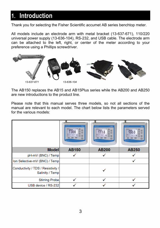
1. Introduction Thank you for selecting the Fisher Scientific accumet AB series benchtop meter. All models include an electrode arm with metal bracket (13-637-671), 110/220 universal power supply (13-636-104), RS-232, and USB cable. The electrode arm can be attached to the left, right, or center of the meter according to your preference using a Phillips screwdriver.
13-637-671 13-636-104
The AB150 replaces the AB15 and AB15Plus series while the AB200 and AB250 are new introductions to the product line. Please note that this manual serves three models, so not all sections of the manual are relevant to each model. The chart below lists the parameters served for the various models:
4
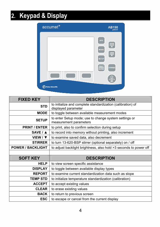
2. Keypad & Display
FIXED KEY DESCRIPTION
STD to initialize and complete standardization (calibration) of displayed parameter
MODE to toggle between available measurement modes
SETUP to enter Setup mode; use to change system settings or measurement parameters
PRINT / ENTER to print, also to confirm selection during setup
SAVE / to record into memory without printing, also increment
VIEW / to examine saved data, also decrement
STIRRER to turn 13-620-BSP stirrer (optional separately) on / off
POWER / BACKLIGHT to adjust backlight brightness, also hold >3 seconds to power off
SOFT KEY DESCRIPTION HELP to view screen specific assistance
DISPLAY to toggle between available display types
REPORT to examine current standardization data such as slope
TEMP STD to initialize temperature standardization (calibration)
ACCEPT to accept existing values
CLEAR to erase existing values
BACK to return to previous screen
ESC to escape or cancel from the current display
5
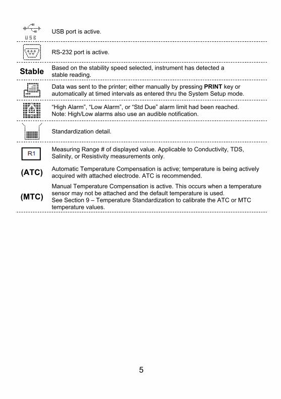
USB port is active.
RS-232 port is active.
Stable Based on the stability speed selected, instrument has detected a stable reading.
Data was sent to the printer; either manually by pressing PRINT key or automatically at timed intervals as entered thru the System Setup mode.
“High Alarm”, “Low Alarm”, or “Std Due” alarm limit had been reached. Note: High/Low alarms also use an audible notification.
Standardization detail.
Measuring Range # of displayed value. Applicable to Conductivity, TDS, Salinity, or Resistivity measurements only.
(ATC) Automatic Temperature Compensation is active; temperature is being actively acquired with attached electrode. ATC is recommended.
(MTC)
Manual Temperature Compensation is active. This occurs when a temperature sensor may not be attached and the default temperature is used. See Section 9 – Temperature Standardization to calibrate the ATC or MTC temperature values.
6
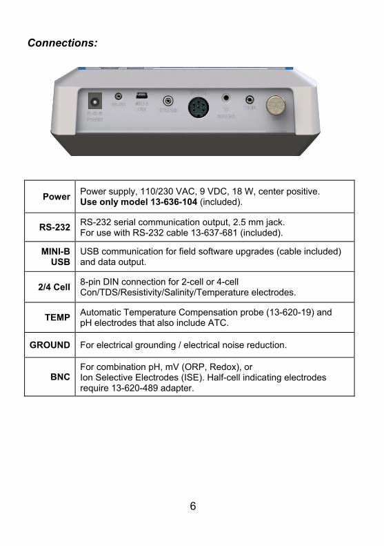
Connections:
Power Power supply, 110/230 VAC, 9 VDC, 18 W, center positive. Use only model 13-636-104 (included).
RS-232 RS-232 serial communication output, 2.5 mm jack. For use with RS-232 cable 13-637-681 (included).
MINI-B USB
USB communication for field software upgrades (cable included) and data output.
2/4 Cell 8-pin DIN connection for 2-cell or 4-cell Con/TDS/Resistivity/Salinity/Temperature electrodes.
TEMP Automatic Temperature Compensation probe (13-620-19) and pH electrodes that also include ATC.
GROUND For electrical grounding / electrical noise reduction.
BNC For combination pH, mV (ORP, Redox), or Ion Selective Electrodes (ISE). Half-cell indicating electrodes require 13-620-489 adapter.
7
3. System Setup & Configuration Use the System Setup to customize operation of your AB series meter. Press SETUP from the measurement screen and then press PRINT/ENTER when SYSTEM is highlighted to access these settings.
The following settings can be customized for each model:
STABILITY STIRRER
EXPORT DATA SAMPLE ID
COMM SETUP LANGUAGE
DATE & TIME BEEP
PASSWORD
FACT RESET
CONTRAST
STABILITY Adjust how quickly and frequently the ‘Stable’ indicator appears. There are four levels of adjustment; SLOW, MEDIUM, FAST, or OFF (prevents the Stable indicator from appearing in measurement mode). To display ‘Stable’ more quickly and more often, use “FAST” setting. MEDIUM or SLOW is recommended for most applications.
SLOW: The ‘Stable’ indicator will take longer to appear and will appear less frequently. Use this setting if you want the best results and don’t mind waiting longer to get them.
MEDIUM: This is the factory default setting. It provides a balanced response which works best for most applications.
FAST: The ‘Stable’ indicator will appear quickest of any setting. If you find that the indicator appears and disappears too frequently, you may want to select a slower setting. This setting is often not suitable for use with most non-refillable (gel filled) electrodes which are generally slower to respond.
Tip: Select a lower pH resolution X.XX instead of X.XXX to decrease stabilization time.
EXPORT DATA Printing: Select ON or OFF.
Datalog: Select ON or OFF.
8
Timed: When either printing or datalog is ON, the option to select Timed readings ON or OFF appears. Select “ON” to automatically print or save data at selectable intervals. Select “OFF” to save data manually using the PRINT/ENTER key.
Time Interval: (MM:SS) (Minutes:Seconds). When timed reading is ON, you must select an interval at which the data will be sent to the Printer and/or Datalog memory. Choose from 3 seconds to 60 minutes. Data will be collected until the data limit is reached or the option is turned “OFF”. This feature is useful for gathering data from a single sample over time. Note that “SAVE” is not available during TIMED setting. To view the stored data, use “VIEW” key.
COMM SETUP (Communication Setup) Format: To send data as a comma separated value, choose CSV – best for exporting data into spreadsheet software. Choose PRINTER to send the data in an easily viewable format – best for printing.
Communication Setup: Choose RS-232 (9600 or 19200 baud rate) or USB.
Baud Rate: When RS-232 is selected, choose (9600 or 19200)
DATE & TIME Setting the correct date and time is required for GLP and will apply to power on, measurement, data log, and print functions. Factory reset will not apply to date and time setting once it has been set. Changes related to daylight savings time must be manually entered.
Date Format: Select (MM DD YY) or (DD MM YY)
Time Format: Select 12Hrs (AM/PM) or 24Hrs
PASSWORD Select “ENABLE” to restrict access to Calibration and Setup modes. When password protection is enabled, password entry is required before performing any calibration, or making changes to the setup mode. Setup parameters can be viewed, but not changed without correct password entry. The password is a user selectable number from 1 to 99999.
Select “DISABLE” if password protection is not desired.
The meter does not allow you to edit setup parameters or perform a new calibration unless you enter the correct password. If an incorrect password is entered 3 consecutive times, the meter returns to measurement mode.
If a password has been ENABLED but cannot be recovered, a password can be provided via a written request. The instrument serial number and your contact information are required.
9
FACT RESET Select “YES” to reset the to the factory default settings except; Date & Time setting, and data stored into memory.
CONTRAST Optimize the contrast setting of your display for best visibility in your surrounding lighting conditions. Test various contrast settings for best results. This setting will be applied to both backlight and non-backlight conditions.
STIRRER Set the stirring speed of the 13-620-BSP Benchtop Stirring Probe (optional accessory) when stirrer is on. Choose from 5 different speeds.
SAMPLE ID This is a user selectable number from 1 to 99999. Incorporating a sample ID to identify one or more data points is useful to distinguish data that is saved into memory or sent to a PC or printer. Use the / key to adjust the values and ENTER to move the cursor of a previous Sample ID.
LANGUAGE Select the preferred language that is displayed on the instrument. Choose from English, Deutsch, 中文, Français, Italiano, & Español.
Tip: Check www.fishersci.com/accumet for free instrument software updates which may include additional languages.
BEEP Enable or disable an audible tone with each key press.
10
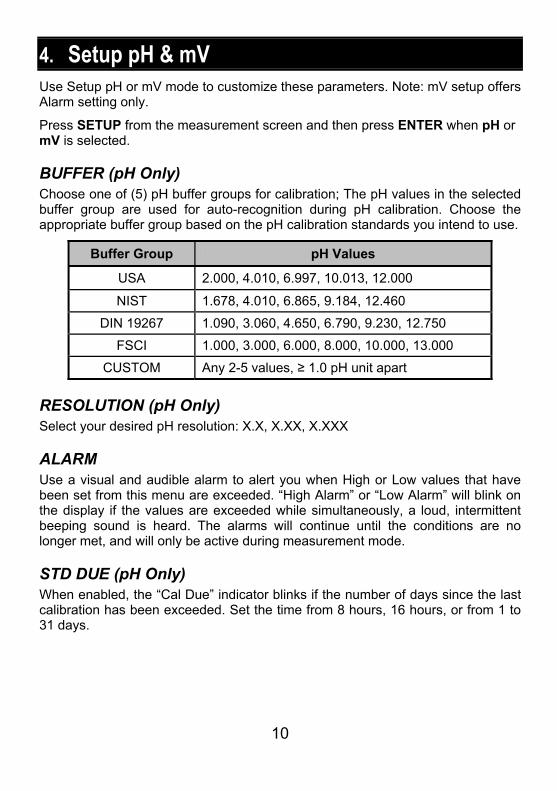
4. Setup pH & mV Use Setup pH or mV mode to customize these parameters. Note: mV setup offers Alarm setting only.
Press SETUP from the measurement screen and then press ENTER when pH or mV is selected.
BUFFER (pH Only) Choose one of (5) pH buffer groups for calibration; The pH values in the selected buffer group are used for auto-recognition during pH calibration. Choose the appropriate buffer group based on the pH calibration standards you intend to use.
Buffer Group pH Values
USA 2.000, 4.010, 6.997, 10.013, 12.000
NIST 1.678, 4.010, 6.865, 9.184, 12.460
DIN 19267 1.090, 3.060, 4.650, 6.790, 9.230, 12.750
FSCI 1.000, 3.000, 6.000, 8.000, 10.000, 13.000
CUSTOM Any 2-5 values, ≥ 1.0 pH unit apart
RESOLUTION (pH Only) Select your desired pH resolution: X.X, X.XX, X.XXX
ALARM Use a visual and audible alarm to alert you when High or Low values that have been set from this menu are exceeded. “High Alarm” or “Low Alarm” will blink on the display if the values are exceeded while simultaneously, a loud, intermittent beeping sound is heard. The alarms will continue until the conditions are no longer met, and will only be active during measurement mode.
STD DUE (pH Only) When enabled, the “Cal Due” indicator blinks if the number of days since the last calibration has been exceeded. Set the time from 8 hours, 16 hours, or from 1 to 31 days.
11
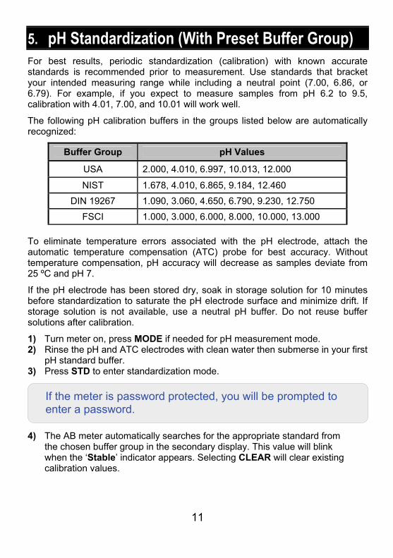
5. pH Standardization (With Preset Buffer Group) For best results, periodic standardization (calibration) with known accurate standards is recommended prior to measurement. Use standards that bracket your intended measuring range while including a neutral point (7.00, 6.86, or 6.79). For example, if you expect to measure samples from pH 6.2 to 9.5, calibration with 4.01, 7.00, and 10.01 will work well.
The following pH calibration buffers in the groups listed below are automatically recognized:
Buffer Group pH Values
USA 2.000, 4.010, 6.997, 10.013, 12.000
NIST 1.678, 4.010, 6.865, 9.184, 12.460
DIN 19267 1.090, 3.060, 4.650, 6.790, 9.230, 12.750
FSCI 1.000, 3.000, 6.000, 8.000, 10.000, 13.000
To eliminate temperature errors associated with the pH electrode, attach the automatic temperature compensation (ATC) probe for best accuracy. Without temperature compensation, pH accuracy will decrease as samples deviate from 25 ºC and pH 7.
If the pH electrode has been stored dry, soak in storage solution for 10 minutes before standardization to saturate the pH electrode surface and minimize drift. If storage solution is not available, use a neutral pH buffer. Do not reuse buffer solutions after calibration.
1) Turn meter on, press MODE if needed for pH measurement mode. 2) Rinse the pH and ATC electrodes with clean water then submerse in your first
pH standard buffer. 3) Press STD to enter standardization mode. 4) The AB meter automatically searches for the appropriate standard from
the chosen buffer group in the secondary display. This value will blink when the ‘Stable’ indicator appears. Selecting CLEAR will clear existing calibration values.
If the meter is password protected, you will be prompted to enter a password.
12
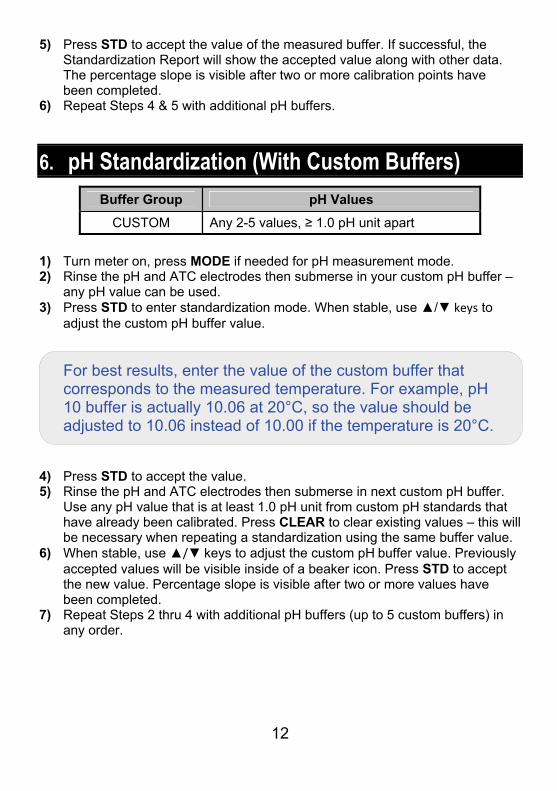
5) Press STD to accept the value of the measured buffer. If successful, the Standardization Report will show the accepted value along with other data. The percentage slope is visible after two or more calibration points have been completed.
6) Repeat Steps 4 & 5 with additional pH buffers.
6. pH Standardization (With Custom Buffers)
Buffer Group pH Values
CUSTOM Any 2-5 values, ≥ 1.0 pH unit apart
1) Turn meter on, press MODE if needed for pH measurement mode. 2) Rinse the pH and ATC electrodes then submerse in your custom pH buffer –
any pH value can be used. 3) Press STD to enter standardization mode. When stable, use / keys to
adjust the custom pH buffer value.
4) Press STD to accept the value. 5) Rinse the pH and ATC electrodes then submerse in next custom pH buffer.
Use any pH value that is at least 1.0 pH unit from custom pH standards that have already been calibrated. Press CLEAR to clear existing values – this will be necessary when repeating a standardization using the same buffer value.
6) When stable, use / keys to adjust the custom pH buffer value. Previously accepted values will be visible inside of a beaker icon. Press STD to accept the new value. Percentage slope is visible after two or more values have been completed.
7) Repeat Steps 2 thru 4 with additional pH buffers (up to 5 custom buffers) in any order.
For best results, enter the value of the custom buffer that corresponds to the measured temperature. For example, pH 10 buffer is actually 10.06 at 20°C, so the value should be adjusted to 10.06 instead of 10.00 if the temperature is 20°C.
13
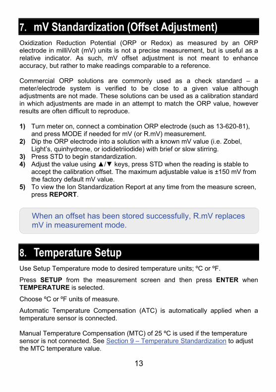
7. mV Standardization (Offset Adjustment) Oxidization Reduction Potential (ORP or Redox) as measured by an ORP electrode in milliVolt (mV) units is not a precise measurement, but is useful as a relative indicator. As such, mV offset adjustment is not meant to enhance accuracy, but rather to make readings comparable to a reference. Commercial ORP solutions are commonly used as a check standard – a meter/electrode system is verified to be close to a given value although adjustments are not made. These solutions can be used as a calibration standard in which adjustments are made in an attempt to match the ORP value, however results are often difficult to reproduce. 1) Turn meter on, connect a combination ORP electrode (such as 13-620-81),
and press MODE if needed for mV (or R.mV) measurement. 2) Dip the ORP electrode into a solution with a known mV value (i.e. Zobel,
Light’s, quinhydrone, or iodidetriiodide) with brief or slow stirring. 3) Press STD to begin standardization. 4) Adjust the value using / keys, press STD when the reading is stable to
accept the calibration offset. The maximum adjustable value is ±150 mV from the factory default mV value.
5) To view the Ion Standardization Report at any time from the measure screen, press REPORT.
8. Temperature Setup Use Setup Temperature mode to desired temperature units; ºC or ºF.
Press SETUP from the measurement screen and then press ENTER when TEMPERATURE is selected.
Choose ºC or ºF units of measure.
Automatic Temperature Compensation (ATC) is automatically applied when a temperature sensor is connected. Manual Temperature Compensation (MTC) of 25 ºC is used if the temperature sensor is not connected. See Section 9 – Temperature Standardization to adjust the MTC temperature value.
When an offset has been stored successfully, R.mV replaces mV in measurement mode.
14
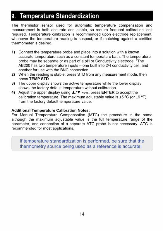
9. Temperature Standardization The thermistor sensor used for automatic temperature compensation and measurement is both accurate and stable, so require frequent calibration isn’t required. Temperature calibration is recommended upon electrode replacement, whenever the temperature reading is suspect, or if matching against a certified thermometer is desired. 1) Connect the temperature probe and place into a solution with a known
accurate temperature such as a constant temperature bath. The temperature probe may be separate or as part of a pH or Conductivity electrode. *The AB200 has two temperature inputs – one built into 2/4 conductivity cell, and another for use with the BNC connection.
2) When the reading is stable, press STD from any measurement mode, then press TEMP STD.
3) The upper display shows the active temperature while the lower display shows the factory default temperature without calibration.
4) Adjust the upper display using / keys, press ENTER to accept the calibration temperature. The maximum adjustable value is ±5 ºC (or ±9 ºF) from the factory default temperature value.
Additional Temperature Calibration Notes: For Manual Temperature Compensation (MTC) the procedure is the same although the maximum adjustable value is the full temperature range of the parameter, and connection of a separate ATC probe is not necessary. ATC is recommended for most applications.
If temperature standardization is performed, be sure that the thermometry source being used as a reference is accurate!
15
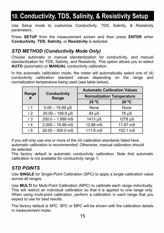
10. Conductivity, TDS, Salinity, & Resistivity Setup Use Setup mode to customize Conductivity, TDS, Salinity, & Resistivity parameters.
Press SETUP from the measurement screen and then press ENTER when Conductivity, TDS, Salinity, or Resistivity is selected.
STD METHOD (Conductivity Mode Only) Choose automatic or manual standardization for conductivity, and manual standardization for TDS, Salinity, and Resistivity. This option allows you to select AUTO (automatic) or MANUAL conductivity calibration.
In the automatic calibration mode, the meter will automatically select one of (4) conductivity calibration standard values depending on the range and normalization temperature being used (see table below).
Range#
Conductivity Range
Automatic Calibration Values
Normalization Temperature
25 ºC 20 ºC
r 1 0.00 – 19.99 µS None None
r 2 20.00 – 199.9 µS 84 µS 76 µS
r 3 200.0 – 1.999 mS 1413 µS 1278 µS
r 4 2.000 – 19.99 mS 12.88 mS 11.67 mS
r 5 20.00 – 500.0 mS 111.8 mS 102.1 mS If you will only use one or more of the (4) calibration standards listed here, automatic calibration is recommended. Otherwise, manual calibration should be selected. The factory default is automatic conductivity calibration. Note that automatic calibration is not available for conductivity range 1.
STD POINTS Use SINGLE for Single-Point Calibration (SPC) to apply a single calibration value across all ranges.
Use MULTI for Multi-Point Calibration (MPC) to calibrate each range individually. This will restrict an individual calibration so that it is applied to one range only. When using multi-point calibration, perform a calibration in each range that you expect to use for best results.
The factory default is SPC. SPC or MPC will be shown with the calibration details in measurement mode.
16
PURE WAT COEF (Pure Water Coefficient) Choose ENABLE to automatically apply pure water temperature correction for measurements below 2 µS/cm (ultra pure water).
Note: this option does not apply to Salinity mode.
TEMP COEFFICIENT (Linear) The temperature coefficient is the amount of change in conductivity per degree temperature (% per ºC). The factory default setting is a temperature coefficient of 2.1 % per ºC. For most applications this will provide good results. The meter allows adjustment from 0.0 to 10.0.
Note: this option does not apply to Salinity mode.
Select 0.0 % for uncompensated measurements. The temperature will be measured by the electrode and displayed in measurement mode – but without compensation.
NORMALIZATION TEMPERATURE (ºC) When Automatic Temperature Compensation is used, measurements are adjusted by the temperature coefficient %, to the normalization temperature. This value is adjustable from 15.0 to 35.0 ºC. Use the normalization temperature that is referenced on your calibration standard(s) – usually 25 ºC.
TDS FACTOR (TDS Mode Only) The TDS conversion factor is a multiplication factor used to convert from conductivity to TDS. The TDS conversion factor automatically adjusts the reading. Select the desired TDS factor from 0.400 to 1.000.
CELL CONST (Cell Constant) The AB200 kit includes a probe with a nominal cell constant (k) of 1.0. Use probes with k = 0.1 and 10 (sold separately) for improved performance in extreme sample ranges. The factory default is 1.0 to match the included probe. Cell constant can be adjusted from 0.010 to 10.000. k = 0.1 ideal for low measurements <20 µS (<10 ppm). k = 1.0 ideal for mid-range measurements k = 10 ideal for high measurements >20 mS (>10 ppt).
17
ALARM Use a visual and audible alarm to alert you when High or Low values that have been set from this menu are exceeded. “High” or “Low” will blink on the display if the values are exceeded while simultaneously, a loud, intermittent beeping sound is heard. The alarms will continue until the conditions are no longer met, and will only be active during measurement mode.
STD DUE When enabled, the “Std Due” indicator blinks if the number of days since the last calibration has been exceeded. Set the time from 8 hours, 16 hours, or from 1 to 31 days.
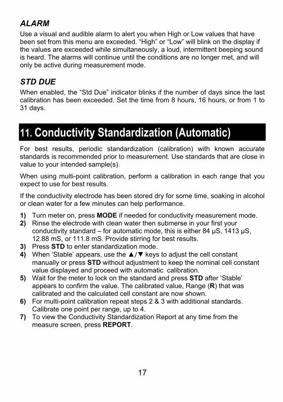
11. Conductivity Standardization (Automatic) For best results, periodic standardization (calibration) with known accurate standards is recommended prior to measurement. Use standards that are close in value to your intended sample(s).
When using multi-point calibration, perform a calibration in each range that you expect to use for best results.
If the conductivity electrode has been stored dry for some time, soaking in alcohol or clean water for a few minutes can help performance.
1) Turn meter on, press MODE if needed for conductivity measurement mode. 2) Rinse the electrode with clean water then submerse in your first your
conductivity standard – for automatic mode, this is either 84 µS, 1413 µS, 12.88 mS, or 111.8 mS. Provide stirring for best results.
3) Press STD to enter standardization mode. 4) When ‘Stable’ appears, use the / keys to adjust the cell constant
manually or press STD without adjustment to keep the nominal cell constant value displayed and proceed with automatic calibration.
5) Wait for the meter to lock on the standard and press STD after ‘Stable’ appears to confirm the value. The calibrated value, Range (R) that was calibrated and the calculated cell constant are now shown.
6) For multi-point calibration repeat steps 2 & 3 with additional standards. Calibrate one point per range, up to 4.
7) To view the Conductivity Standardization Report at any time from the measure screen, press REPORT.
18
Additional Notes On Automatic Conductivity Calibration: A maximum of one calibration point per range can be performed. If multiple calibration points are used in the same range, the most recent one will replace the previous one.
If the electrode is replaced, it is best to clear the calibration to the factory default values.
Rinse or immerse the probe before standardization and between samples with clean water (deionized water is ideal).
For best results always begin with your lowest calibration standard value, followed by the next lowest, and so on.
Low conductivity standard solutions (less than 20 µS) are unstable and are very temperature dependent. As a result, reproducible calibration results are challenging in lowest measurement range (0.00 to 20.0 µS).
12. Cond/TDS/Salinity/Resistivity Standardization (Manual Adjustment)
For best results, periodic standardization (calibration) with known accurate standards is recommended prior to measurement. Use standards that are close in value to your intended sample(s).
When using multi-point calibration (MPC), perform a calibration in each range that you expect to use for best results.
If the conductivity electrode has been stored dry for some time, soaking in alcohol or clean water for a few minutes can help performance.
1) Turn meter on, press MODE if needed for the appropriate mode. 2) Rinse the electrode with clean water then submerse in your first your
conductivity standard. Press STD to enter standardization mode. 3) When ‘Stable’ appears, use the / keys to adjust the cell constant
manually or press STD without adjustment to keep the nominal cell constant value displayed and proceed with automatic calibration.
“2 Cell’ or “4 Cell’ electrode is automatically detected and displayed on the measurement screen when connected.
19
4) The upper display is the active reading while the lower display is the factory default value. Use the / keys to adjust the upper display to match the desired value.
5) Press STD after ‘Stable’ appears to confirm the value. The calibrated value, Range (R) that was calibrated and the calculated cell constant are now shown.
6) For multi-point calibration repeat steps 2 thru 5 with additional standards. Calibrate one point per range, up to 5.
7) To view the Conductivity Standardization Report at any time from the measure screen, press REPORT.
Additional Manual Calibration Notes: A maximum of one calibration point per range can be performed. If multiple calibration points are used in the same range, the most recent one will replace the previous one.
When the electrode is replaced, it is best to clear the calibration to the factory default values.
Rinse or immerse the probe before calibration and between samples with clean water (deionized water is ideal).
For best results always begin with your lowest calibration standard value, followed by the next lowest, and so on.
Low conductivity standard solutions (less than 20 µS) are unstable and are very temperature dependent. As a result, reproducible calibration results are challenging in lowest measurement range #1 (0.00 to 20.0 µS).
20
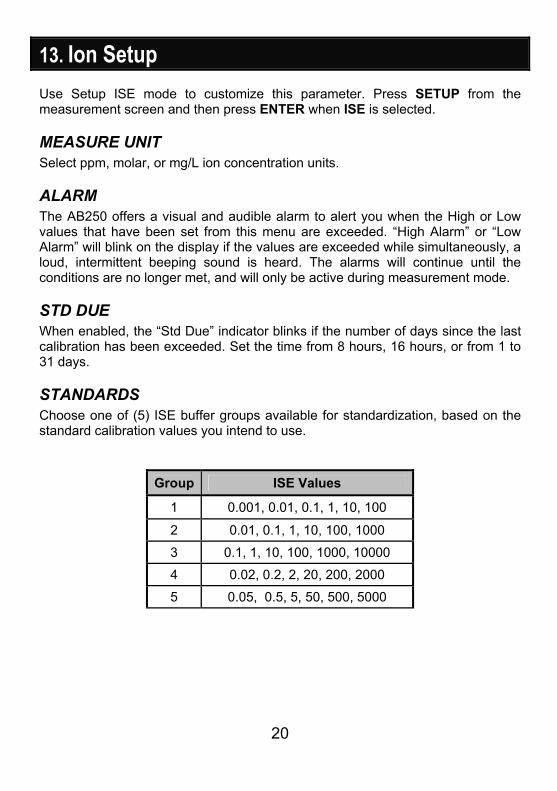
13. Ion Setup Use Setup ISE mode to customize this parameter. Press SETUP from the measurement screen and then press ENTER when ISE is selected.
MEASURE UNIT Select ppm, molar, or mg/L ion concentration units.
ALARM The AB250 offers a visual and audible alarm to alert you when the High or Low values that have been set from this menu are exceeded. “High Alarm” or “Low Alarm” will blink on the display if the values are exceeded while simultaneously, a loud, intermittent beeping sound is heard. The alarms will continue until the conditions are no longer met, and will only be active during measurement mode.
STD DUE When enabled, the “Std Due” indicator blinks if the number of days since the last calibration has been exceeded. Set the time from 8 hours, 16 hours, or from 1 to 31 days.
STANDARDS Choose one of (5) ISE buffer groups available for standardization, based on the standard calibration values you intend to use.
Group ISE Values
1 0.001, 0.01, 0.1, 1, 10, 100
2 0.01, 0.1, 1, 10, 100, 1000
3 0.1, 1, 10, 100, 1000, 10000
4 0.02, 0.2, 2, 20, 200, 2000
5 0.05, 0.5, 5, 50, 500, 5000
21
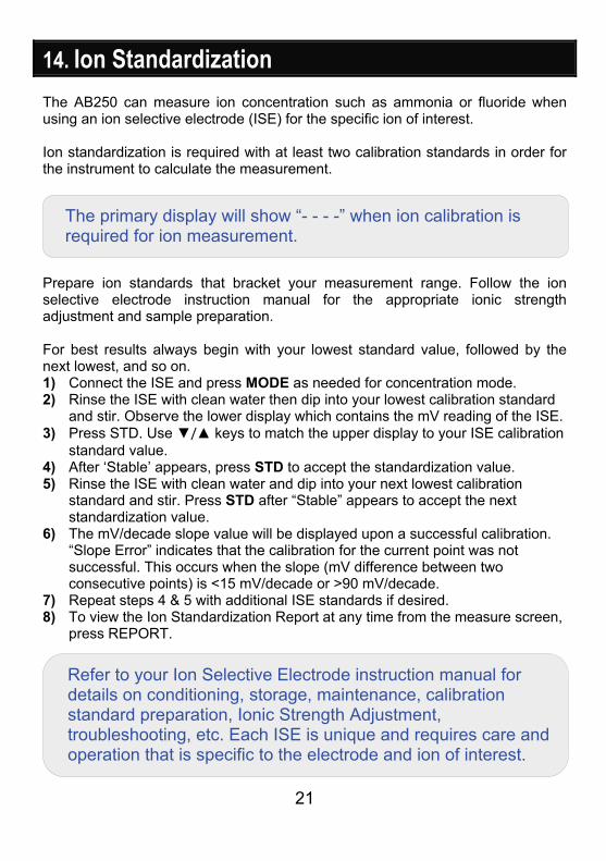
14. Ion Standardization The AB250 can measure ion concentration such as ammonia or fluoride when using an ion selective electrode (ISE) for the specific ion of interest. Ion standardization is required with at least two calibration standards in order for the instrument to calculate the measurement.
Prepare ion standards that bracket your measurement range. Follow the ion selective electrode instruction manual for the appropriate ionic strength adjustment and sample preparation. For best results always begin with your lowest standard value, followed by the next lowest, and so on. 1) Connect the ISE and press MODE as needed for concentration mode. 2) Rinse the ISE with clean water then dip into your lowest calibration standard
and stir. Observe the lower display which contains the mV reading of the ISE. 3) Press STD. Use / keys to match the upper display to your ISE calibration
standard value. 4) After ‘Stable’ appears, press STD to accept the standardization value. 5) Rinse the ISE with clean water and dip into your next lowest calibration
standard and stir. Press STD after “Stable” appears to accept the next standardization value.
6) The mV/decade slope value will be displayed upon a successful calibration. “Slope Error” indicates that the calibration for the current point was not successful. This occurs when the slope (mV difference between two consecutive points) is <15 mV/decade or >90 mV/decade.
7) Repeat steps 4 & 5 with additional ISE standards if desired. 8) To view the Ion Standardization Report at any time from the measure screen,
press REPORT.
The primary display will show “- - - -” when ion calibration is required for ion measurement.
Refer to your Ion Selective Electrode instruction manual for details on conditioning, storage, maintenance, calibration standard preparation, Ionic Strength Adjustment, troubleshooting, etc. Each ISE is unique and requires care and operation that is specific to the electrode and ion of interest.
22
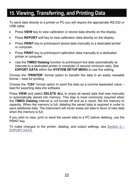
15. Viewing, Transferring, and Printing Data To send data directly to a printer or PC you will require the appropriate RS-232 or USB cable.
Press VIEW key to view calibration or stored data directly on the display.
Press REPORT soft key to view calibration data directly on the display.
Press PRINT key to print/export stored data manually to a dedicated printer or computer.
Press PRINT key to print/export calibration data manually to a dedicated printer or computer.
Use the TIMED Datalog function to print/export live data automatically at intervals to a dedicated printer or computer (3 second minimum rate). See EXPORT DATA within the SYSTEM SETUP MENU to use this setting.
Choose the “PRINTER” format option to transfer the data in an easily viewable format – best for printing.
Choose the “CSV” format option to send the data as a comma separated value –best for exporting data into software
Press VIEW and select DELETE ALL to erase all saved data that was manually or automatically stored into memory. This step is most commonly required when the TIMED Datalog interval is not turned off and as a result, fills the memory to capacity. When the memory is full, deleting the saved data is required in order to save additional data. The instrument will never erase old data in favor of new data when the memory is full.
If you wish to view, print or send the saved data to a PC before deleting, use the PRINT key.
To make changes to the printer, datalog, and output settings, see Section 3 –EXPORT DATA.
23
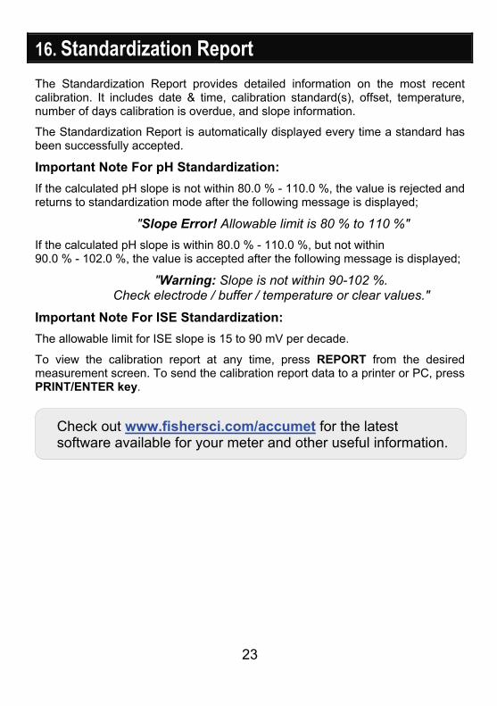
16. Standardization Report The Standardization Report provides detailed information on the most recent calibration. It includes date & time, calibration standard(s), offset, temperature, number of days calibration is overdue, and slope information.
The Standardization Report is automatically displayed every time a standard has been successfully accepted.
Important Note For pH Standardization:
If the calculated pH slope is not within 80.0 % - 110.0 %, the value is rejected and returns to standardization mode after the following message is displayed;
"Slope Error! Allowable limit is 80 % to 110 %" If the calculated pH slope is within 80.0 % - 110.0 %, but not within 90.0 % - 102.0 %, the value is accepted after the following message is displayed;
"Warning: Slope is not within 90-102 %. Check electrode / buffer / temperature or clear values."
Important Note For ISE Standardization:
The allowable limit for ISE slope is 15 to 90 mV per decade.
To view the calibration report at any time, press REPORT from the desired measurement screen. To send the calibration report data to a printer or PC, press PRINT/ENTER key.
Check out www.fishersci.com/accumet for the latest software available for your meter and other useful information.
24
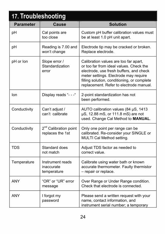
17. Troubleshooting Parameter Cause Solution
pH Cal points are too close
Custom pH buffer calibration values must be at least 1.0 pH unit apart.
pH Reading is 7.00 and won’t change
Electrode tip may be cracked or broken. Replace electrode.
pH or Ion Slope error / Standardization error
Calibration values are too far apart, or too far from ideal values. Check the electrode, use fresh buffers, and check meter settings. Electrode may require filling solution, conditioning, or complete replacement. Refer to electrode manual.
Ion Display reads “- - -“ 2-point standardization has not been performed.
Conductivity Can’t adjust / can’t calibrate
AUTO calibration values (84 µS, 1413 µS, 12.88 mS, or 111.8 mS) are not used. Change Cal Method to MANUAL.
Conductivity 2nd Calibration point replaces the 1st
Only one point per range can be calibrated. Re-consider your SINGLE or MULTI Cal Method setting.
TDS Standard does not match
Adjust TDS factor as needed to correct value.
Temperature Instrument reads inaccurate temperature
Calibrate using water bath or known accurate thermometer. Faulty thermistor – repair or replace.
ANY “OR” or “UR” error message
Over Range or Under Range condition. Check that electrode is connected.
ANY I forgot my password
Please send a written request with your name, contact information, and instrument serial number; a temporary
25
password will be provided.
ALL My problem is not listed here.
Please contact your Fisher Scientific representative or email technical support directly with your feedback: [email protected]
18. USB Driver & Boot Loader Documentation This document is intended to guide the reader through the process of A) installing the USB driver for communication with a PC, and B) boot loading (upgrading) the latest firmware for Fisher Scientific accumet® AB150, AB200, and AB250 series meters which may become available. USB Driver Installation Guide For Windows XP: To install the USB device driver under Windows XP, follow the instructions below. This will allow your computer to recognize the instrument.
1. Obtain the USB driver file (via web download, disc, email, etc.) and save on your computer in a location that can be easily found.
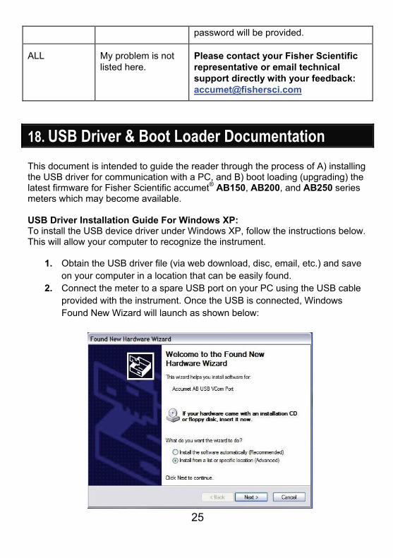
2. Connect the meter to a spare USB port on your PC using the USB cable provided with the instrument. Once the USB is connected, Windows Found New Wizard will launch as shown below:
26
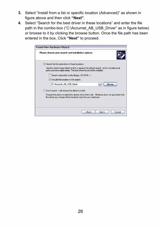
3. Select “Install from a list or specific location (Advanced)” as shown in figure above and then click “Next”.
4. Select “Search for the best driver in these locations” and enter the file path in the combo-box (“C:\Accumet_AB_USB_Driver” as in figure below) or browse to it by clicking the browse button. Once the file path has been entered in the box, Click “Next” to proceed.
27
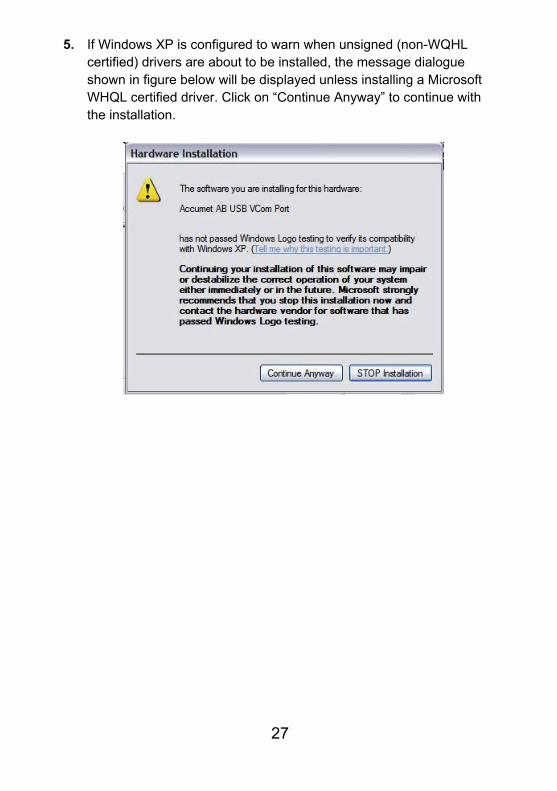
5. If Windows XP is configured to warn when unsigned (non-WQHL certified) drivers are about to be installed, the message dialogue shown in figure below will be displayed unless installing a Microsoft WHQL certified driver. Click on “Continue Anyway” to continue with the installation.
28
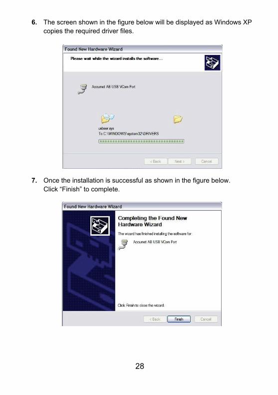
6. The screen shown in the figure below will be displayed as Windows XP copies the required driver files.
7. Once the installation is successful as shown in the figure below. Click “Finish” to complete.
29
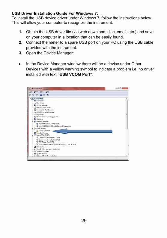
USB Driver Installation Guide For Windows 7: To install the USB device driver under Windows 7, follow the instructions below. This will allow your computer to recognize the instrument.
1. Obtain the USB driver file (via web download, disc, email, etc.) and save on your computer in a location that can be easily found.
2. Connect the meter to a spare USB port on your PC using the USB cable provided with the instrument.
3. Open the Device Manager:
In the Device Manager window there will be a device under Other Devices with a yellow warning symbol to indicate a problem i.e. no driver installed with text “USB VCOM Port”.
30
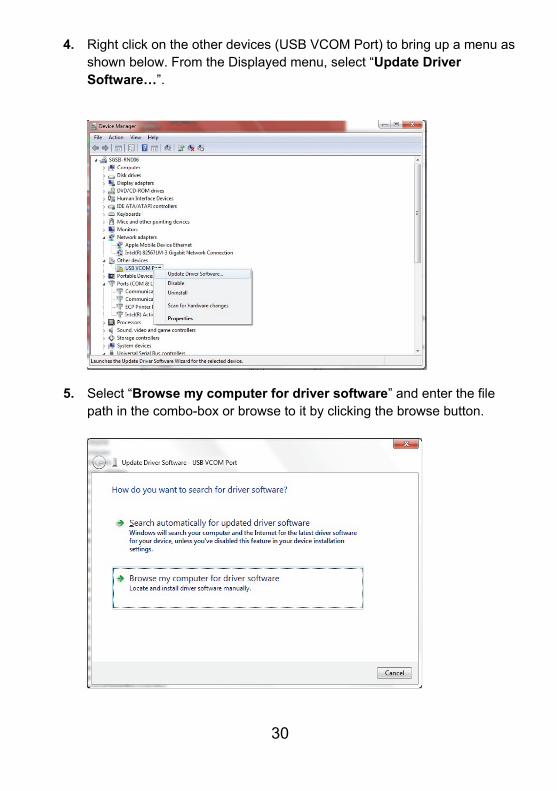
4. Right click on the other devices (USB VCOM Port) to bring up a menu as shown below. From the Displayed menu, select “Update Driver Software…”.
5. Select “Browse my computer for driver software” and enter the file path in the combo-box or browse to it by clicking the browse button.
31
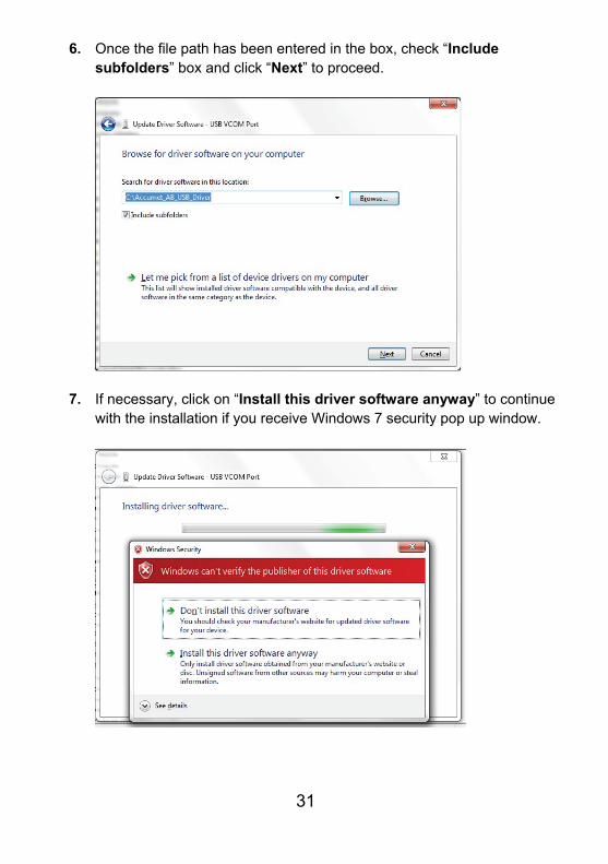
6. Once the file path has been entered in the box, check “Include subfolders” box and click “Next” to proceed.
7. If necessary, click on “Install this driver software anyway” to continue with the installation if you receive Windows 7 security pop up window.
32
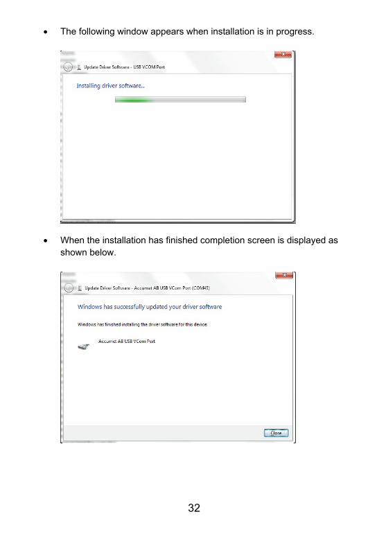
The following window appears when installation is in progress.
When the installation has finished completion screen is displayed as shown below.
33
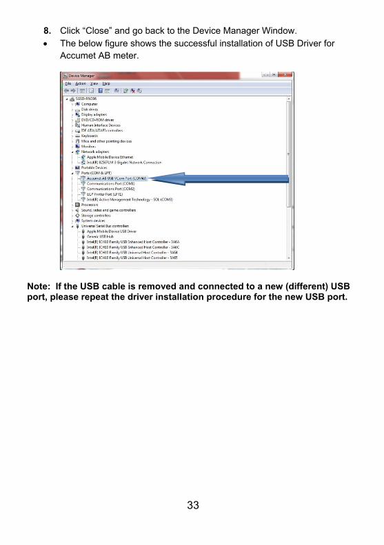
8. Click “Close” and go back to the Device Manager Window. The below figure shows the successful installation of USB Driver for
Accumet AB meter.
Note: If the USB cable is removed and connected to a new (different) USB port, please repeat the driver installation procedure for the new USB port.
34
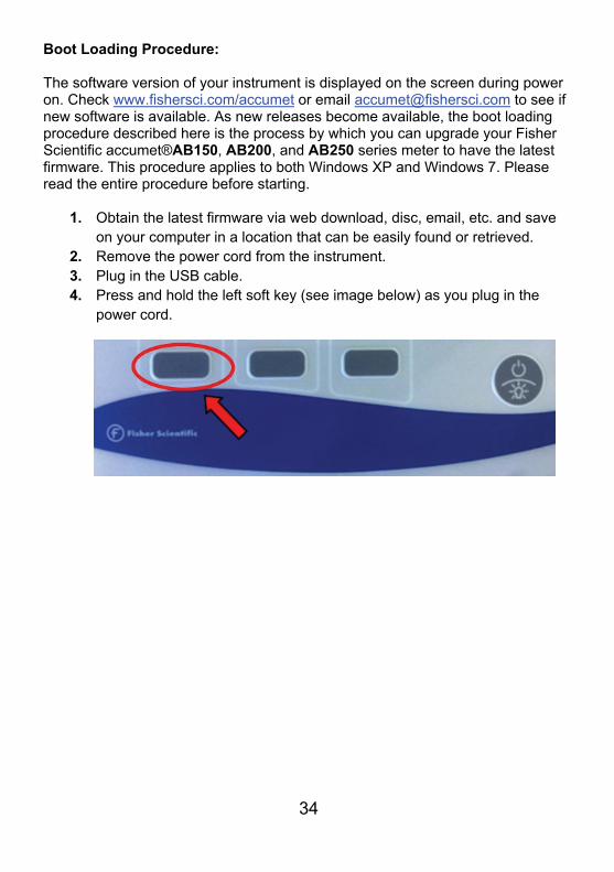
Boot Loading Procedure: The software version of your instrument is displayed on the screen during power on. Check www.fishersci.com/accumet or email [email protected] to see if new software is available. As new releases become available, the boot loading procedure described here is the process by which you can upgrade your Fisher Scientific accumet®AB150, AB200, and AB250 series meter to have the latest firmware. This procedure applies to both Windows XP and Windows 7. Please read the entire procedure before starting.
1. Obtain the latest firmware via web download, disc, email, etc. and save on your computer in a location that can be easily found or retrieved.
2. Remove the power cord from the instrument. 3. Plug in the USB cable. 4. Press and hold the left soft key (see image below) as you plug in the
power cord.
35
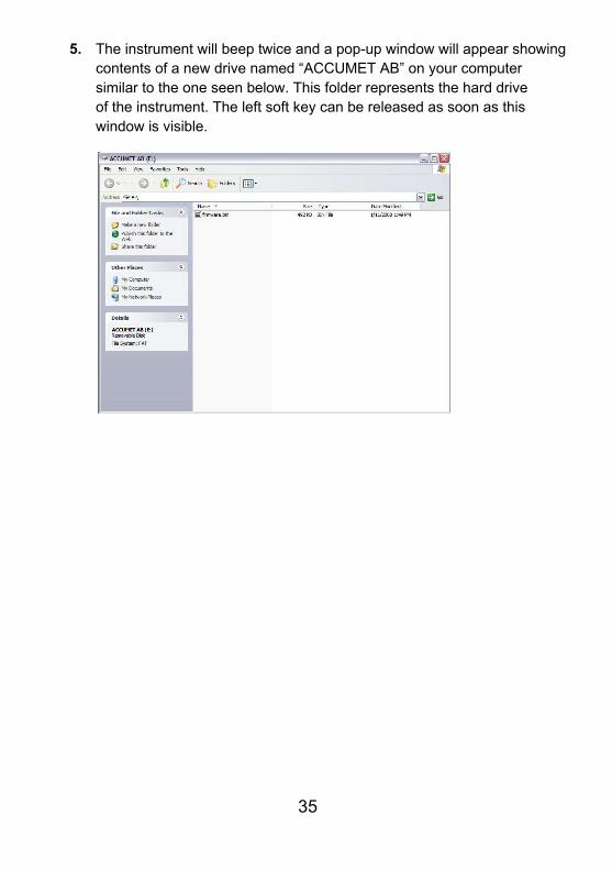
5. The instrument will beep twice and a pop-up window will appear showing contents of a new drive named “ACCUMET AB” on your computer similar to the one seen below. This folder represents the hard drive of the instrument. The left soft key can be released as soon as this window is visible.
36
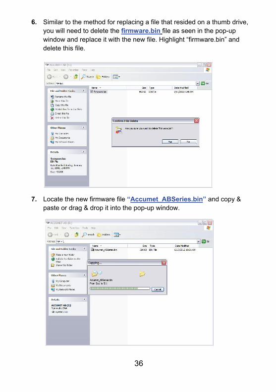
6. Similar to the method for replacing a file that resided on a thumb drive, you will need to delete the firmware.bin file as seen in the pop-up window and replace it with the new file. Highlight “firmware.bin” and delete this file.
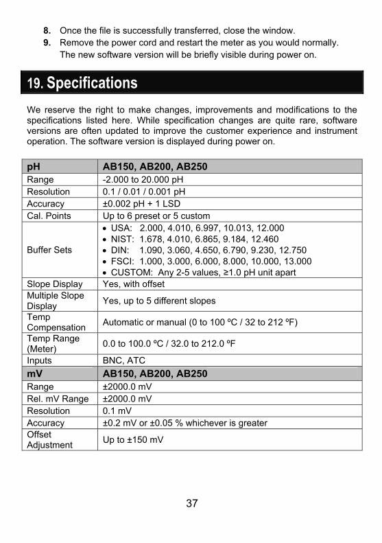
7. Locate the new firmware file “Accumet_ABSeries.bin” and copy & paste or drag & drop it into the pop-up window.
37
8. Once the file is successfully transferred, close the window. 9. Remove the power cord and restart the meter as you would normally.
The new software version will be briefly visible during power on.
19. Specifications We reserve the right to make changes, improvements and modifications to the specifications listed here. While specification changes are quite rare, software versions are often updated to improve the customer experience and instrument operation. The software version is displayed during power on. pH AB150, AB200, AB250 Range -2.000 to 20.000 pH Resolution 0.1 / 0.01 / 0.001 pH Accuracy ±0.002 pH + 1 LSD Cal. Points Up to 6 preset or 5 custom
Buffer Sets
USA: 2.000, 4.010, 6.997, 10.013, 12.000 NIST: 1.678, 4.010, 6.865, 9.184, 12.460 DIN: 1.090, 3.060, 4.650, 6.790, 9.230, 12.750 FSCI: 1.000, 3.000, 6.000, 8.000, 10.000, 13.000 CUSTOM: Any 2-5 values, ≥1.0 pH unit apart
Slope Display Yes, with offset Multiple Slope Display
Yes, up to 5 different slopes
Temp Compensation
Automatic or manual (0 to 100 ºC / 32 to 212 ºF)
Temp Range (Meter)
0.0 to 100.0 ºC / 32.0 to 212.0 ºF
Inputs BNC, ATC
mV AB150, AB200, AB250 Range ±2000.0 mV Rel. mV Range ±2000.0 mV Resolution 0.1 mV Accuracy ±0.2 mV or ±0.05 % whichever is greater Offset Adjustment
Up to ±150 mV
38
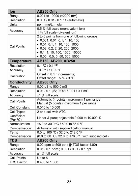
Ion AB250 Only Range 0.001 to 19999 (±2000 mV) Resolution 0.001 / 0.01 / 0.1 / 1 (automatic) Units ppm, mg/L, molar
Accuracy 0.5 % full scale (monovalent ion) 1 % full scale (divalent ion)
Cal Points
2 to 6 points from one of following groups; 0.001, 0.01, 0.1, 1, 10, 100 0.01, 0.1, 1, 10, 100, 1000 0.02, 0.2, 2, 20, 200, 2000 0.1, 1, 10, 100, 1000, 10000 0.05, 0.5, 5, 50, 500, 5000
Temperature AB150, AB200, AB250 Resolution 0.1 ºC / 0.1 ºF Accuracy ±0.3 ºC / ±0.5 ºF
Calibration Offset in 0.1 º increments; Offset range: ±5 ºC / 9 ºF
Conductivity AB200 Only Range 0.00 µS to 500.0 mS Resolution 0.01 / 0.1 µS; 0.001 / 0.01 / 0.1 mS Accuracy ±1 % full scale
Cal. Points Automatic (4 points); maximum 1 per range Manual (5 points); maximum 1 per range
Cell Constant 0.010 to 10.000 Cell Types 2 or 4 cell with ATC Coefficient (Per ºC)
Linear & pure; adjustable 0.000 to 10.000 %
Normalization 15.0 to 30.0 ºC / 59.0 to 86.0 ºF Compensation Automatic with supplied cell or manual Temp Compensation
0.0 to 100 ºC / 32.0 to 212.0 ºF (0.0 to 80 ºC / 32.0 to 176.0 ºF with supplied cell)
TDS AB200 Only Range 0.00 ppm to 500 ppt (@ TDS factor 1.00) Resolution 0.01 / 0.1 ppm ; 0.001 / 0.01 / 0.1 ppt Accuracy ±1 % full scale Cal. Points Up to 5 TDS Factor 0.400 to 1.000
39
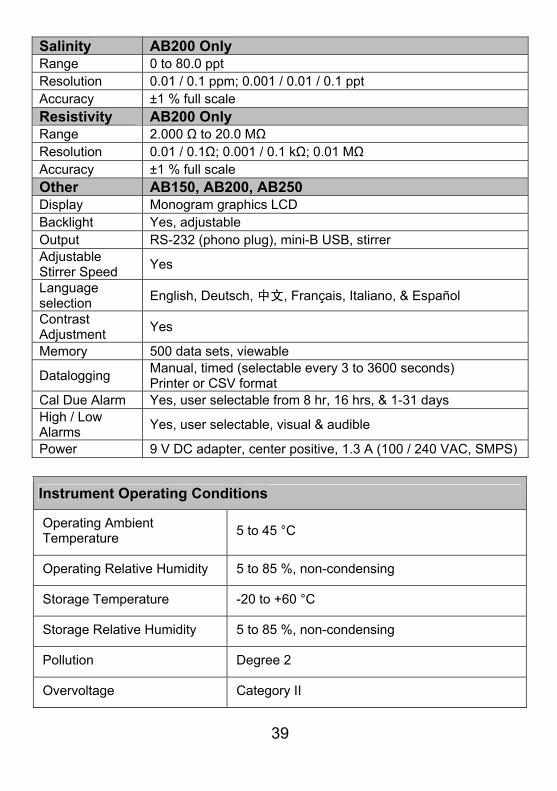
Salinity AB200 Only Range 0 to 80.0 ppt Resolution 0.01 / 0.1 ppm; 0.001 / 0.01 / 0.1 ppt Accuracy ±1 % full scale Resistivity AB200 Only Range 2.000 Ω to 20.0 MΩ Resolution 0.01 / 0.1Ω; 0.001 / 0.1 kΩ; 0.01 MΩ Accuracy ±1 % full scale Other AB150, AB200, AB250 Display Monogram graphics LCD Backlight Yes, adjustable Output RS-232 (phono plug), mini-B USB, stirrer Adjustable Stirrer Speed
Yes
Language selection
English, Deutsch, 中文, Français, Italiano, & Español
Contrast Adjustment
Yes
Memory 500 data sets, viewable
Datalogging Manual, timed (selectable every 3 to 3600 seconds) Printer or CSV format
Cal Due Alarm Yes, user selectable from 8 hr, 16 hrs, & 1-31 days High / Low Alarms
Yes, user selectable, visual & audible
Power 9 V DC adapter, center positive, 1.3 A (100 / 240 VAC, SMPS)
Instrument Operating Conditions
Operating Ambient Temperature
5 to 45 °C
Operating Relative Humidity 5 to 85 %, non-condensing
Storage Temperature -20 to +60 °C
Storage Relative Humidity 5 to 85 %, non-condensing
Pollution Degree 2
Overvoltage Category II
40
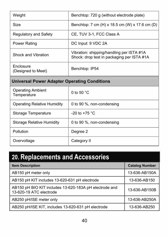
Weight Benchtop: 720 g (without electrode plate)
Size Benchtop: 7 cm (H) x 18.5 cm (W) x 17.6 cm (D)
Regulatory and Safety CE, TUV 3-1, FCC Class A
Power Rating DC Input: 9 VDC 2A
Shock and Vibration Vibration: shipping/handling per ISTA #1A Shock: drop test in packaging per ISTA #1A
Enclosure (Designed to Meet)
Benchtop: IP54
Universal Power Adapter Operating Conditions
Operating Ambient Temperature
0 to 50 °C
Operating Relative Humidity 0 to 90 %, non-condensing
Storage Temperature -20 to +75 °C
Storage Relative Humidity 0 to 90 %, non-condensing
Pollution Degree 2
Overvoltage Category II
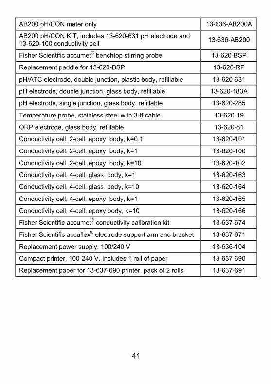
20. Replacements and Accessories Item Description Catalog Number
AB150 pH meter only 13-636-AB150A
AB150 pH KIT includes 13-620-631 pH electrode 13-636-AB150
AB150 pH BIO KIT includes 13-620-183A pH electrode and 13-620-19 ATC electrode
13-636-AB150B
AB250 pH/ISE meter only 13-636-AB250A
AB250 pH/ISE KIT, includes 13-620-631 pH electrode 13-636-AB250
41
AB200 pH/CON meter only 13-636-AB200A
AB200 pH/CON KIT, includes 13-620-631 pH electrode and 13-620-100 conductivity cell
13-636-AB200
Fisher Scientific accumet® benchtop stirring probe 13-620-BSP
Replacement paddle for 13-620-BSP 13-620-RP
pH/ATC electrode, double junction, plastic body, refillable 13-620-631
pH electrode, double junction, glass body, refillable 13-620-183A
pH electrode, single junction, glass body, refillable 13-620-285
Temperature probe, stainless steel with 3-ft cable 13-620-19
ORP electrode, glass body, refillable 13-620-81
Conductivity cell, 2-cell, epoxy body, k=0.1 13-620-101
Conductivity cell, 2-cell, epoxy body, k=1 13-620-100
Conductivity cell, 2-cell, epoxy body, k=10 13-620-102
Conductivity cell, 4-cell, glass body, k=1 13-620-163
Conductivity cell, 4-cell, glass body, k=10 13-620-164
Conductivity cell, 4-cell, epoxy body, k=1 13-620-165
Conductivity cell, 4-cell, epoxy body, k=10 13-620-166
Fisher Scientific accumet® conductivity calibration kit 13-637-674
Fisher Scientific accuflex® electrode support arm and bracket 13-637-671
Replacement power supply, 100/240 V 13-636-104
Compact printer, 100-240 V. Includes 1 roll of paper 13-637-690
Replacement paper for 13-637-690 printer, pack of 2 rolls 13-637-691
42
21. Warranty The Fisher Scientific Company (“Fisher”) warrants to the direct purchaser that the accumet meters and accumet, accuTupH, and accupHast, electrodes will be free from defects in material or workmanship for a specified warranty period. During that period, Fisher will repair or replace the product or provide credit, at its sole option, upon prompt notification and compliance with its instructions. For accumet meter, that specified period is 36 months from delivery date. For electrodes, that specified period is 12 months. Unless otherwise agreed, the warranty is limited to the country in which the product is sold. No Fisher employee, agent or representative has the authority to bind Fisher to any oral representation or warranty concerning any product sold. Any oral representation or warranty made prior to purchase of any product and not set forth in writing and signed by a duly authorized officer of Fisher shall not be enforceable by the purchaser.
FISHER EXPRESSLY DISCLAIMS ALL OTHER WARRANTIES, EXPRESS OR IMPLIED WARRANTY OF MERCHANTABILITY AND FITNESS FOR A PARTICULAR PURPOSE.
Fisher’s sole responsibility and the purchaser’s exclusive remedy for any claim arising out of the purchase or any product listed above is repair, replacement or credit as described above, where applicable. In no event: 1) shall the cost of the exclusive remedy exceed the purchase price: 2) shall Fisher be liable for any special, indirect, incidental, consequential, or exemplary damages, howsoever arising, even if Fisher has been advised of the possibility of such damages. Each article that Fisher furnishes will conform to the written specifications given in this manual, or those of a further improved model. Changes are made often to the information in the manual and will be incorporated into future edition.
22. Return of Items A “Return Goods Authorization” (RGA) must be obtained from our Customer Service Department or before returning items for any reason. Please include data regarding the reason the items are to be returned. For your protection, items must be carefully packed to prevent damage in shipment and insured against possible damage or loss. We will not be responsible for damage resulting from careless or insufficient packing. A restocking charge will apply to all unauthorized returns.
43
23. Notice of Compliance
This equipment generates, uses, and can radiate radio frequency energy and if
not installed and used in accordance with the instruction manual, may cause
interference to radio communications. It has been tested and found to comply
with the limits for a Class A computing device pursuant to Subpart J of Part 15
of FCC Rules, which are designed to provide reasonable protection against
such interference when operated in a commercial environment. Operation of
this equipment in a residential area is likely to cause interference in which case
the user, at his own expense, will be required to take whatever measures may
be required to correct the interference.
“This digital apparatus does not exceed the (Class A) limits for radio noise
emissions from digital apparatus set out in the Radio Interference Regulations
of the Canadian Department of Communications.”
“Le present appareil numerique n’ emet pas de bruits radioelectriques
depassant les limites applicables aux appareils numeriques (de la class A)
prescrites dans le Reglement sur le brouillage radioelectrique edicte par le
ministere des Communications du Canada.”
WEEE Compliance This product is required to comply with the European Union’s Waste
Electrical & Electronic Equipment (WEEE) Directive 2002/96/EC. It is
marked with the symbol on the left.
Thermo Fisher Scientific has contracted with one or more recycling/disposal
companies in each EU Member State and this product should be disposed of or
recycled through them. Further information on compliance with these
directives, the recyclers in your country, and product information that may
assist the detection of substances subject to the RoHS Directive are available
from www.thermofisher.com.
44
24. Declaration of Conformity Manufacturer: Thermo Fisher Scientific, Inc. Address: Ayer Rajah Crescent
Blk 55 #04-16/24 Singapore 139949 Singapore
Hereby declares that the following products rated 100-240 VAC, 50/60 Hz, 2A:
Fisher Scientific accumet AB150 Fisher Scientific accumet AB200 Fisher Scientific accumet AB250
Equipment Class: Measurement, control and laboratory, EMC Class A
Conforms to the following directives and standards:
EN61326-1:2006 Electromagnetic Compatibility
(EMC Directive) Electrical equipment for measurement, control and laboratory use – EMC requirements
EN61010-1:2001 Safety Standards UL61010-1:2004 CAN/CSA C22.2 No. 61010-1-04
Safety requirements for electrical equipment for measurement, control and laboratory use – general requirements
_____________________ Cheow Kwang Chan QA/Regulatory Manager
Place & Date of Issue: July 2012, Singapore

45
For technical assistence contact your Fisher Scientific representative or visit: www.fishersci.com/accumet or email [email protected]
Thermo Fisher Scientific (Australia) +1300-735-292 thermofisher.com.au Fisher Scientific GmbH (Austria) 0043-800-208840 at.fishersci.com Fisher Scientific (Belgium) 056-260-260 be.fishersci.com Fisher Scientific (Canada) 1-800-234-7437 fishersci.ca Fisher Scientific (China) +400-881-5117 fishersci.com.cn Fisher Scientific SPOL. S.R.O. (Czech Republic) +420-466-798-230 thermofisher.cz Fisher Scientific (Denmark) +45-70-27-99-20 fishersci.dk Fisher Scientific (Finland) +358-9-8027-6280 fishersci.fi Fisher Scientific (France) 03-88-67-53-20 fr.fishersci.com Fisher Scientific GmbH (Germany) 0049-2304-932-5 de.fishersci.com Fisher Scientific (India) +1-800-209-7001 fishersci.in Fisher Scientific (Ireland) +35-301-899-5854 ie.fishersci.com Fisher Scientific (Italy) 02-953-28-258 it.fishersci.com Fisher Scientific (Korea) +02-527-0300 fishersci.co.kr Fisher Scientific (Malaysia) +603-5122-8888 fishersci.com.my Fisher Scientific (Netherlands) 020-487-70-00 nl.fishersci.com Thermo Fisher Scientific (New Zealand) +0800-933-966 thermofisher.co.nz Fisher Scientific (Norway) +47-22-95-59-59 fishersci.no Fisher Scientific (Portugal) 21-425-33-50 pt.fishersci.com Fisher Scientific (Singapore) +65-6873-6006 fishersci.com.sg Fisher Scientific (South East Asia) +65-6873-6006 fishersci.com.sg Fisher Scientific (Spain) 902-239-303 es.fishersci.com Fisher Scientific (Sweden) +46-31-352-32-00 fishersci.se Fisher Scientific (Switzerland) 056-618-41-11 ch.fishersci.com Fisher Scientific (United Kingdom) +01-509-231166 fisher.co.uk Fisher Scientific (United States) 1-800-766-7000 fishersci.com
© 2012 Thermo Fisher Scientific Inc. All rights reserved.
Fisher Scientific accumet® Basic (AB) Benchtop Meters AB150
AB200
AB250