instruction manual eng - lns-america.com turbo hb instruction... · turbo hb 2.1. transportation...
TRANSCRIPT
LNS SA CH-2534 Orvinwww.LNS-group.com
Instruction manual ENG


TURBO HB
V2.00
TABLE OF CONTENTS CHAPTER 1: INTRODUCTION ........................... ........................................................ 1-1
1.1. Basic introduction ........................... ................................................................................................. 1-2
1.1.1. Symbols and terminology ............................................................................................................ 1-2
1.2. Rights ....................................... ......................................................................................................... 1-3
1.3. Characteristics .............................. ................................................................................................... 1-4
1.3.1. Floor plans .................................................................................................................................. 1-4
CHAPTER 2: SETTING INTO OPERATION ................. ............................................... 2-1
2.1. Transportation ............................... ................................................................................................... 2-2
2.2. Unpacking .................................... ..................................................................................................... 2-2
2.3. Lifting the conveyor ......................... ................................................................................................ 2-3
2.4. Fitting the castors ......................... .................................................................................................. 2-3
2.5. Safety devices ............................... ................................................................................................... 2-5
2.5.1. Description .................................................................................................................................. 2-5
2.5.2. Layout of the safety elements on the conveyor .......................................................................... 2-5
2.5.3. Installation safety ........................................................................................................................ 2-6
2.5.4. Security analysis for the correct incorporation ............................................................................ 2-7
2.6. Installation and startup ..................... ............................................................................................... 2-8
2.6.1. Conveyor Drive ........................................................................................................................... 2-8
2.6.2. Leveling ....................................................................................................................................... 2-8
2.6.3. Connection to the machine ......................................................................................................... 2-8
2.6.4. Electrical connection ................................................................................................................... 2-9
2.6.5. Setting the voltage of the motor – Direct drive version ............................................................. 2-10
2.6.6. Electrical control ........................................................................................................................ 2-10
CHAPTER 3: CONVEYOR BELT .......................... ...................................................... 3-1
3.1. Belt Direction ............................... ..................................................................................................... 3-2
3.2. Belt tensioning – Checking the tension ....... .................................................................................. 3-2
3.3. Belt Tensioning – How to tension the belt .... ................................................................................. 3-4
3.4. Belt removal and installation ................ .......................................................................................... 3-5
3.6. Belt assemblies .............................. .................................................................................................. 3-9
3.6.1. Standard and Heavy Duty belts .................................................................................................. 3-9
3.6.2. Super Heavy Duty belts ............................................................................................................ 3-10
TURBO HB
CHAPTER 4: MAINTENANCE ............................ ........................................................ 4-1
4.1. Periodic inspection .......................... ................................................................................................. 4-2
4.1.1. After first 100 hours ..................................................................................................................... 4-2
4.2. Cleaning ..................................... ........................................................................................................ 4-2
4.3. Factors affecting performance ................ ........................................................................................ 4-2
CHAPTER 5: OPTIONS ................................ .............................................................. 5-1
5.1. Air header ................................... ....................................................................................................... 5-2
5.2. Chip stripper bar ............................ ................................................................................................... 5-4
5.3. Spare parts .................................. ...................................................................................................... 5-5
5.3.1. Layout of the elements – Direct drive version ............................................................................. 5-5
CHAPTER 6: APPENDICES ............................. .......................................................... 6-1
Appendix A: Ordering form ......................... ........................................................................................... 6-2
Appendix B: Address LNS ........................... ........................................................................................... 6-3

CHAPTER 1: INTRODUCTION 1-1
TURBO HB
CHAPTER 1: INTRODUCTION
1-2 CHAPTER 1: INTRODUCTION
TURBO HB
1.1. Basic introduction LNS conveyors simply and reliably remove waste from machining operations. Machine efficiency is increased and operator safety is improved since the conveyors work with little operator attention and without interrupting production time. LNS SA conveyors are available for many types of machine tools or other applications. They can be arranged to deliver wet or dry waste to containers or to conveyor or chute-type disposal systems. For further information, contact LNS.
The TURBO HB conveyor was specifically designed to handle a wide variety of materials and applications where filtration is not required. Its simple yet robust construction ensures it offers a long, continuous, trouble free operation in the most demanding of today’s machining environments. Combining the latest conveyor technology and user friendliness, it provides efficient chip removal, while remaining simple to use and highly reliable. Given its compact assembly, TURBO HB requires very little space, and allows for optimum use of the work surface.
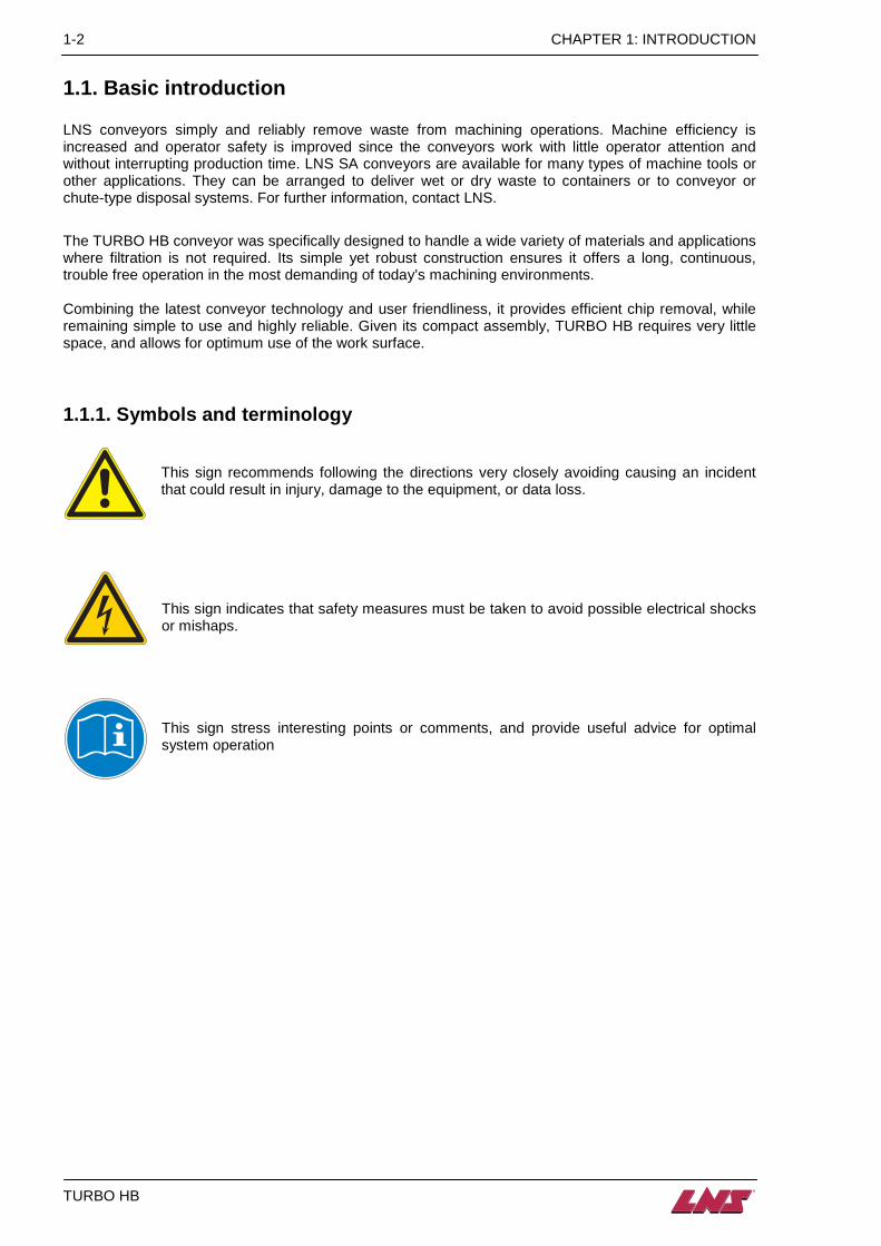
1.1.1. Symbols and terminology
This sign recommends following the directions very closely avoiding causing an incident that could result in injury, damage to the equipment, or data loss.
This sign indicates that safety measures must be taken to avoid possible electrical shocks or mishaps.
This sign stress interesting points or comments, and provide useful advice for optimal system operation

CHAPTER 1 : INTRODUCTION 1-3
TURBO HB
1.2. Rights All rights reserved. Reproduction, recording or transmission of all, or any portion, of this manual, in any form or through any means whatsoever, whether mechanical, photographic, sound or other, without the express written authorization of LNS SA, is prohibited. LNS SA disclaims all responsibility for errors which may be contained in this manual and the problems which may result therefrom. LNS SA and its subsidiaries cannot be made responsible for the debts, losses, expenses, or damage incurred, or suffered, by the buyer of this product, or a third party, following an accident, incorrect use, or misuse, or stemming from modifications, repairs, or transformations not authorized by LNS SA. LNS SA and its subsidiaries cannot be held responsible for damage and problems arising from the use of options and products other than LNS products, or products approved by LNS SA. The names of the products indicated in this manual are registered trademarks. All information contained in this manual is entented to be correct, however information and data in this manual are subject to change without notice. LNS SA makes no warranty of any kind of regard to this information or data. Further, LNS SA is not responsible for any omissions or errors or consequential damage caused by the user of the product. LNS SA reserves the right to make manufacturing changes which may not be included in this manual. LNS SA supplies data necessary for the proper instruction, test, operation and maintenance of this product. LNS SA.retains all proprietary rights in and to the information so disclosed and such shall not be reproduced, copied, or used in whole or in part for purposes other than those for which it is furnished.

1-4 CHAPTER 1: INTRODUCTION
TURBO HB
1.3. Characteristics Depending on the country and the standards in effect, certain technical data, such as the power supply, may vary. Please see the technical card delivered with the device.
1.3.1. Floor plans Each conveyor varies in size depending on the machine tool it is designed to fit to. Above is a general diagram which can be used to help in communications with LNS SA regarding size queries and enquiries.
Drawing dimension Conveyor terminology
A Baffle width B Frame height C Baffle height D Frame width E Baffle length F Covered load G Tail height H Load length I Overall length J Incline angle K Height above floor L Discharge height M Overall height
Type Standard duty [mm] Heavy duty [mm] Super heavy duty
Sidewing height 19 (0.75") 25.4(+1.00") 38.1 (+1.50") 25(+1.00") 38.1 (+1.50")
W-Width BW +50.8 (+2") BW +91.95 (+3.62") BW +98.5 (+3.875")
T-Height 123 (4.84") 170 (6.69") 211 (8.31")
178 (+7.00") 219(+8.62")
C B
M E
L
F
H
I
K
J G
A
D

CHAPTER 2: SETTING INTO OPERATION 2-1
TURBO HB
CHAPTER 2: SETTING INTO OPERATION
2-2 CHAPTER 2: SETTING INTO OPERATION
TURBO HB
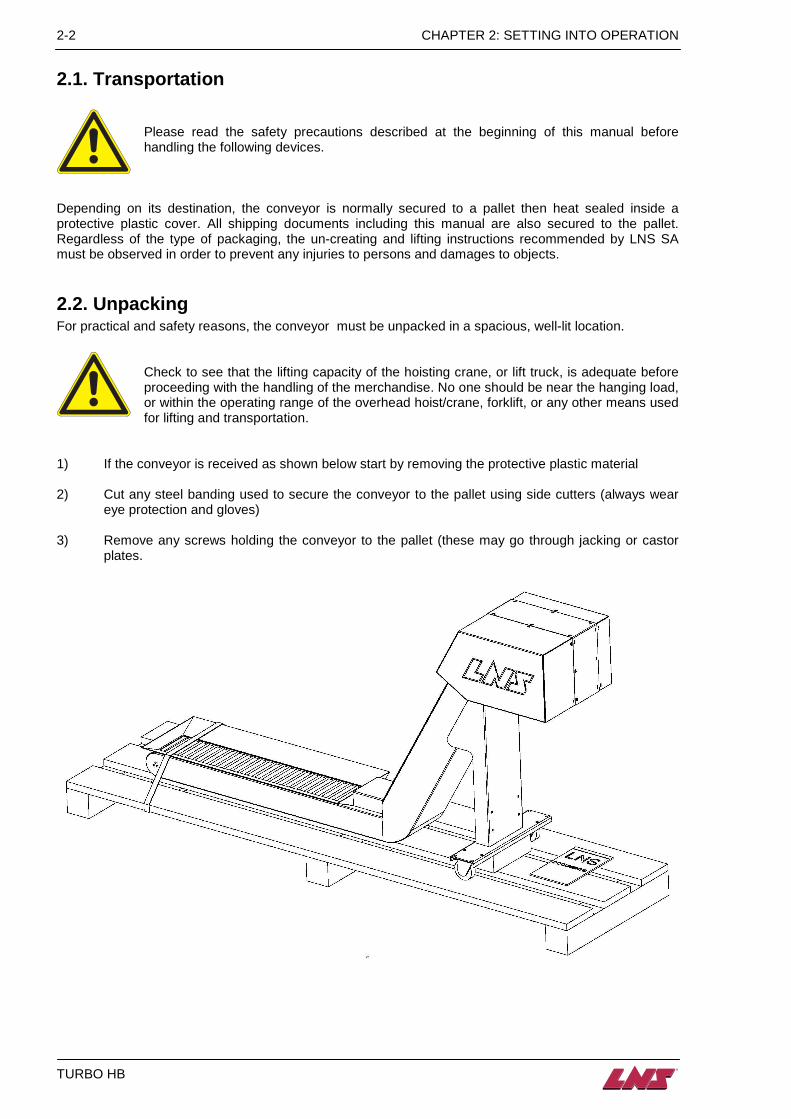
2.1. Transportation
Please read the safety precautions described at the beginning of this manual before handling the following devices.
Depending on its destination, the conveyor is normally secured to a pallet then heat sealed inside a protective plastic cover. All shipping documents including this manual are also secured to the pallet. Regardless of the type of packaging, the un-creating and lifting instructions recommended by LNS SA must be observed in order to prevent any injuries to persons and damages to objects.
2.2. Unpacking For practical and safety reasons, the conveyor must be unpacked in a spacious, well-lit location.
Check to see that the lifting capacity of the hoisting crane, or lift truck, is adequate before proceeding with the handling of the merchandise. No one should be near the hanging load, or within the operating range of the overhead hoist/crane, forklift, or any other means used for lifting and transportation.
1) If the conveyor is received as shown below start by removing the protective plastic material 2) Cut any steel banding used to secure the conveyor to the pallet using side cutters (always wear
eye protection and gloves) 3) Remove any screws holding the conveyor to the pallet (these may go through jacking or castor
plates.
CHAPTER 2: SETTING INTO OPERATION 2-3
TURBO HB
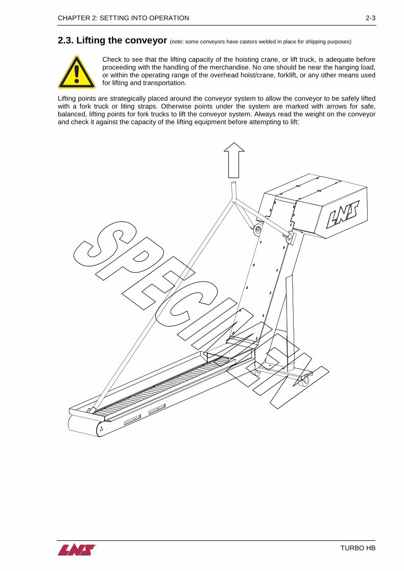
2.3. Lifting the conveyor (note: some conveyors have castors welded in place for shipping purposes)
Check to see that the lifting capacity of the hoisting crane, or lift truck, is adequate before proceeding with the handling of the merchandise. No one should be near the hanging load, or within the operating range of the overhead hoist/crane, forklift, or any other means used for lifting and transportation.
Lifting points are strategically placed around the conveyor system to allow the conveyor to be safely lifted with a fork truck or liting straps. Otherwise points under the system are marked with arrows for safe, balanced, lifting points for fork trucks to lift the conveyor system. Always read the weight on the conveyor and check it against the capacity of the lifting equipment before attempting to lift:

2-4 CHAPTER 2: SETTING INTO OPERATION
TURBO HB
2.4. Fitting the castors
Before attempting to fit the castors ensure the conveyors weight is properly and securely off the castor plate and the conveyor is properly balanced to prevent injusry.
Depending on the specific design of conveyor the castors may either be welded to the conveyor or bolted to the conveyor. If they are bolted to the conveyor they are normally shipped bolted upside sown to the castor plate for stability in transport if this is the case then they will need to be fitted prior to installation. Please see the drawing below for the castor assembly:
Designation Description 1 M10 bolts 2 M10 lock washers 3 M10 washers 4 Castor 5 M10 nuts 6 Castor plate
5
3
2
4
6
1
CHAPTER 2: SETTING INTO OPERATION 2-5
TURBO HB
2.5. Safety devices The LNS Company, or its local representative, may not be held responsible for possible accidents or property damage, whether caused directly or not, by any means whatsoever, if certain safety devices have not been included.
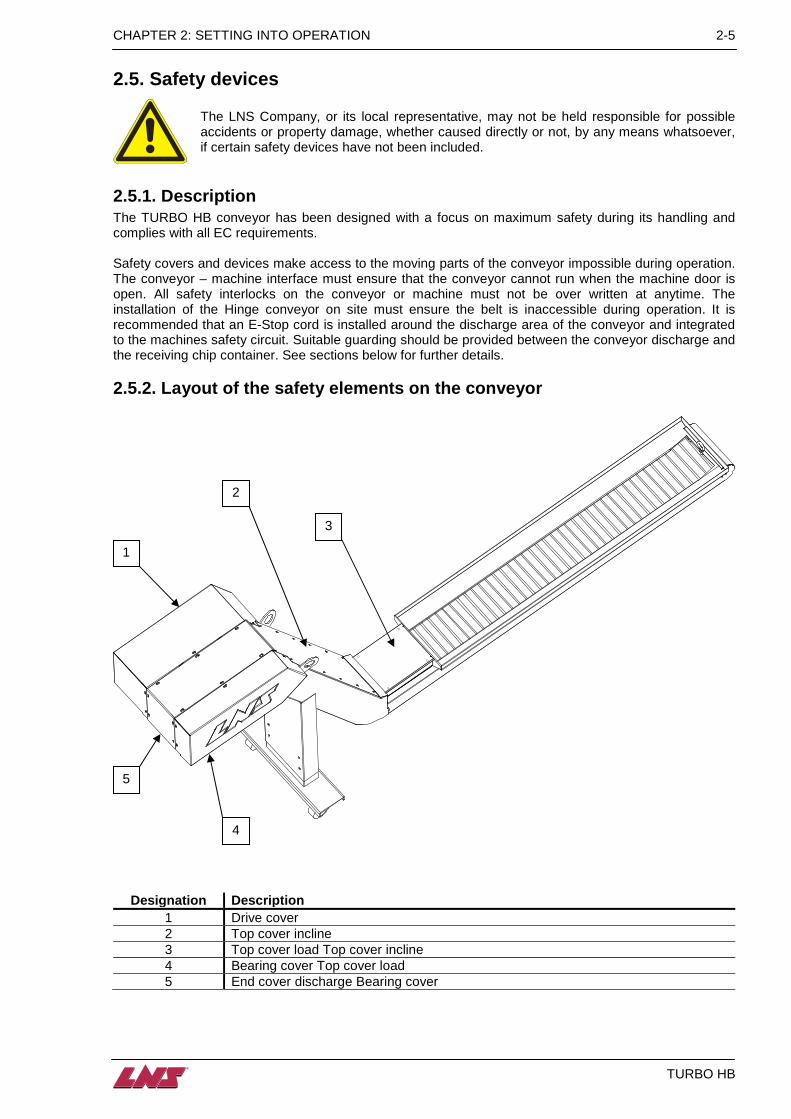
2.5.1. Description The TURBO HB conveyor has been designed with a focus on maximum safety during its handling and complies with all EC requirements. Safety covers and devices make access to the moving parts of the conveyor impossible during operation. The conveyor – machine interface must ensure that the conveyor cannot run when the machine door is open. All safety interlocks on the conveyor or machine must not be over written at anytime. The installation of the Hinge conveyor on site must ensure the belt is inaccessible during operation. It is recommended that an E-Stop cord is installed around the discharge area of the conveyor and integrated to the machines safety circuit. Suitable guarding should be provided between the conveyor discharge and the receiving chip container. See sections below for further details. 2.5.2. Layout of the safety elements on the conveyo r
Designation Description 1 Drive cover 2 Top cover incline 3 Top cover load Top cover incline 4 Bearing cover Top cover load 5 End cover discharge Bearing cover
4
5
1
2
3
2-6 CHAPTER 2: SETTING INTO OPERATION
TURBO HB
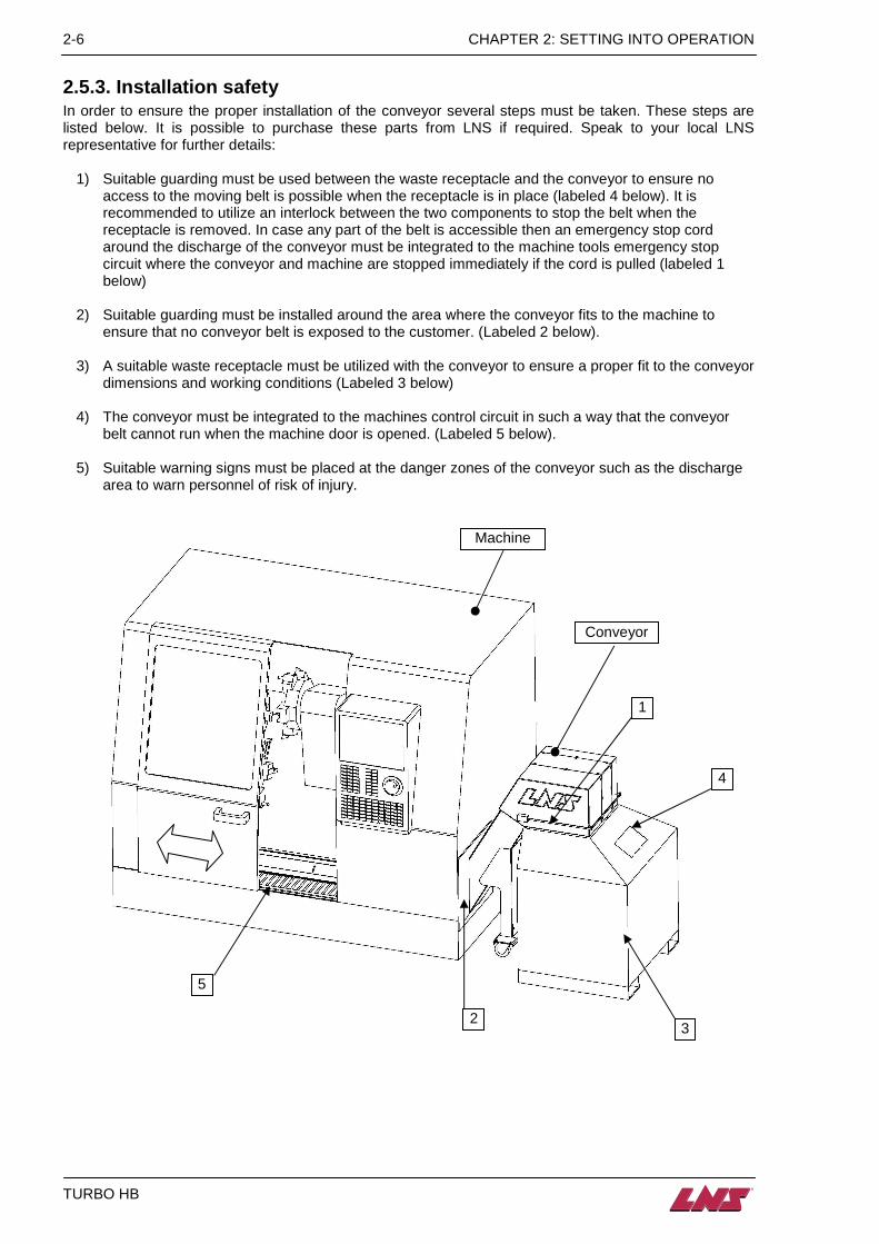
2.5.3. Installation safety In order to ensure the proper installation of the conveyor several steps must be taken. These steps are listed below. It is possible to purchase these parts from LNS if required. Speak to your local LNS representative for further details:
1) Suitable guarding must be used between the waste receptacle and the conveyor to ensure no access to the moving belt is possible when the receptacle is in place (labeled 4 below). It is recommended to utilize an interlock between the two components to stop the belt when the receptacle is removed. In case any part of the belt is accessible then an emergency stop cord around the discharge of the conveyor must be integrated to the machine tools emergency stop circuit where the conveyor and machine are stopped immediately if the cord is pulled (labeled 1 below)
2) Suitable guarding must be installed around the area where the conveyor fits to the machine to ensure that no conveyor belt is exposed to the customer. (Labeled 2 below).
3) A suitable waste receptacle must be utilized with the conveyor to ensure a proper fit to the conveyor dimensions and working conditions (Labeled 3 below)
4) The conveyor must be integrated to the machines control circuit in such a way that the conveyor belt cannot run when the machine door is opened. (Labeled 5 below).
5) Suitable warning signs must be placed at the danger zones of the conveyor such as the discharge area to warn personnel of risk of injury.
Machine
Conveyor
1
2 3
4
5

CHAPTER 2: SETTING INTO OPERATION 2-7
TURBO HB
2.5.4. Security analysis for the correct incorporat ion Before considering assembling the machine, it is necessary to consider the following points::
• Consider security strategies that reduce risks to an acceptable level;
• Define the tasks required for applications to predict and assess the need of access and / or for the approach;
• Identify sources of risks, including failures and failure modes associated with each task. Risks can come from:
o machine in which the device is integrated;
o its association with other equipment,
• Evaluate and assess the risks associated by using the machine
o programming risks
o operation risks
o risks of use
o maintenance risks
• Choose methods of protection :
o the use of protective devices
o the introduction of signals
o compliance with safe work procedures

2-8 CHAPTER 2: SETTING INTO OPERATION
TURBO HB
2.6. Installation and startup Your conveyor has been run prior to shipment to insure proper operation. However, it is recommended that the following checks be made before startup:
2.6.1. Conveyor Drive • Check frame and belt for damage during shipment or storage. • Locate conveyor in operating position inside the machine (see separate specific interface instructions). • All drive elements (pulleys and sprockets) should be located close to their bearing supports. Each set
of pulleys and sprockets should be carefully aligned to prevent excessive wear and noise. • Belt should be properly tensioned.
2.6.2. Leveling A level should be placed across tail section and on the conveyor belt inline with the direction of travel of the belt. Adjust the conveyor or tanks castors to ensure the system is level. If the system is not equiped with leving castors or jacking screws then it may be necessary to shim the system to make it level. When the conveyor is installed to the machine it may be necessary to level the conveyor by adjusting the setting of the conveyor leg in conjunction with a level. See the diagram below for details.
2.6.3. Connection to the machine Once the conveyor has been installed to the machine, the conveyor must be connected to the interface of the machine and if an Air header is supplied an air supply must be connected to the conveyor. At this stage all guards must be in place as indicated in the specific installation instructions and in this manual. For the electrical connection, please see section 2.6.4. and, if an electrical control is supplied, the electrical drawing in side the conveyors electrical box. If an Air header is supplied the pneumatic (airline) must be connected to the Air header inlet as indicated in chapter 5, section 5.1.
Loosen the 4 bolts and tighten them once the leg is set.
Raise / lower the leg until the conveyor is level.
CHAPTER 2: SETTING INTO OPERATION 2-9
TURBO HB
2.6.4. Electrical connection
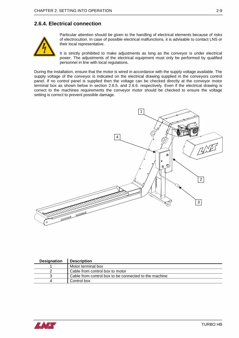
Particular attention should be given to the handling of electrical elements because of risks of electrocution. In case of possible electrical malfunctions, it is advisable to contact LNS or their local representative. It is strictly prohibited to make adjustments as long as the conveyor is under electrical power. The adjustments of the electrical equipment must only be performed by qualified personnel in line with local regulations.
During the installation, ensure that the motor is wired in accordance with the supply voltage available. The supply voltage of the conveyor is indicated on the electrical drawing supplied in the conveyors control panel. If no control panel is supplied then the voltage can be checked directly at the conveyor motor terminal box as shown below in section 2.6.5. and 2.6.6. respectively. Even if the electrical drawing is correct to the machines requirements the conveyor motor should be checked to ensure the voltage setting is correct to prevent possible damage.
Designat ion Description 1 Motor terminal box 2 Cable from control box to motor 3 Cable from control box to be connected to the machine 4 Control box
1
2
3
4
2-10 CHAPTER 2: SETTING INTO OPERATION
TURBO HB
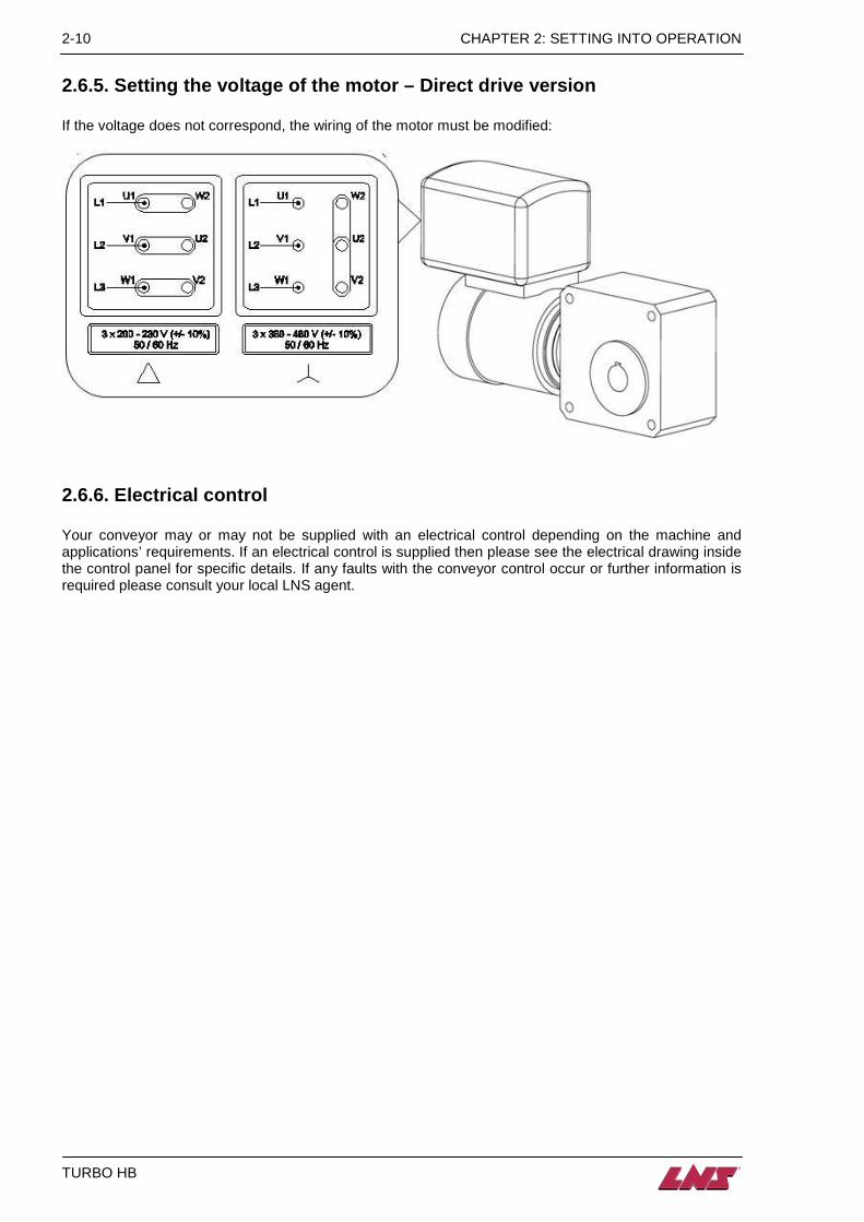
2.6.5. Setting the voltage of the motor – Direct dr ive version If the voltage does not correspond, the wiring of the motor must be modified:
2.6.6. Electrical control Your conveyor may or may not be supplied with an electrical control depending on the machine and applications’ requirements. If an electrical control is supplied then please see the electrical drawing inside the control panel for specific details. If any faults with the conveyor control occur or further information is required please consult your local LNS agent.

CHAPTER 3: CONVEYOR BELT 3-1
TURBO HB
CHAPTER 3: CONVEYOR BELT
3-2 CHAPTER 3: CONVEYOR BELT
TURBO HB
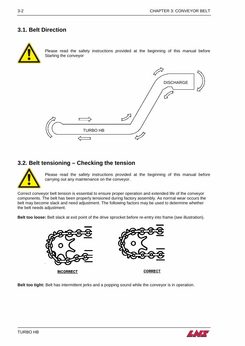
3.1. Belt Direction
Please read the safety instructions provided at the beginning of this manual before Starting the conveyor
3.2. Belt tensioning – Checking the tension Please read the safety instructions provided at the beginning of this manual before carrying out any maintenance on the conveyor.
Correct conveyor belt tension is essential to ensure proper operation and extended life of the conveyor components. The belt has been properly tensioned during factory assembly. As normal wear occurs the belt may become slack and need adjustment. The following factors may be used to determine whether the belt needs adjustment.
Belt too loose: Belt slack at exit point of the drive sprocket before re-entry into frame (see illustration).
Belt too tight: Belt has intermittent jerks and a popping sound while the conveyor is in operation.
TURBO HB
DISCHARGE

CHAPTER 3: CONVEYOR BELT 3-3
TURBO HB
Uneven tension (side to side): The belt tends to track to one side. An indication of this is excessive wear on outside of side wings as shown below:
Check to see that the clutch body is square to the bearing mounting bracket. If it is not, this will generally indicate which direction the belt is off on side to side tension.
Once it is determined that re-tensioning of the belt is necessary, the following procedure should be followed:
Excessive wear will be seen on the edge of the side wing.
3-4 CHAPTER 3: CONVEYOR BELT
TURBO HB
3.3. Belt Tensioning – How to tension the belt (Torque wrench required)
1. Install the belt as stated in Section “belt installation” below, except do not install the drive cover, bearing cover or tension the belt. (Pre-load exaggerates and/or alters torque reading.)
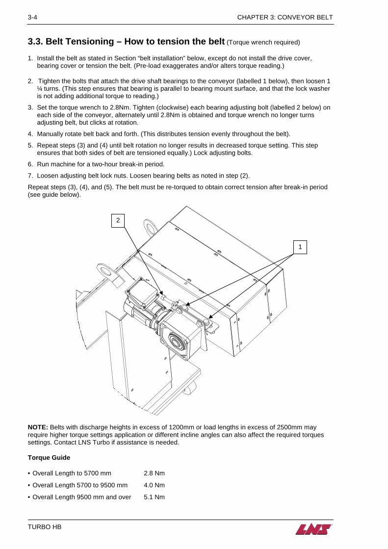
2. Tighten the bolts that attach the drive shaft bearings to the conveyor (labelled 1 below), then loosen 1 ¼ turns. (This step ensures that bearing is parallel to bearing mount surface, and that the lock washer is not adding additional torque to reading.)
3. Set the torque wrench to 2.8Nm. Tighten (clockwise) each bearing adjusting bolt (labelled 2 below) on each side of the conveyor, alternately until 2.8Nm is obtained and torque wrench no longer turns adjusting belt, but clicks at rotation.
4. Manually rotate belt back and forth. (This distributes tension evenly throughout the belt).
5. Repeat steps (3) and (4) until belt rotation no longer results in decreased torque setting. This step ensures that both sides of belt are tensioned equally.) Lock adjusting bolts.
6. Run machine for a two-hour break-in period.
7. Loosen adjusting belt lock nuts. Loosen bearing belts as noted in step (2).
Repeat steps (3), (4), and (5). The belt must be re-torqued to obtain correct tension after break-in period (see guide below).
NOTE: Belts with discharge heights in excess of 1200mm or load lengths in excess of 2500mm may require higher torque settings application or different incline angles can also affect the required torques settings. Contact LNS Turbo if assistance is needed.
Torque Guide • Overall Length to 5700 mm 2.8 Nm
• Overall Length 5700 to 9500 mm 4.0 Nm
• Overall Length 9500 mm and over 5.1 Nm
2
1

CHAPTER 3: CONVEYOR BELT 3-5
TURBO HB
3.4. Belt removal and installation
Please read the safety instructions provided at the beginning of this manual before carrying out any maintenance on the conveyor.
1. Remove the motor cover from the discharge. 2. One by one loosen and remove the 2 nuts and bolts connecting the motor mounting plate to the
torque arm on the bearing bracket. Once the bolts are removed the motor can be slid off the drive shaft as shown below:
3. Loosen the lock nuts on the belt tension adjusting screws (see drawing below) and back off the belt
tensioning adjusting screws (see drawing below) until they are flush with the face of the adjusting bracket.
4. Loosen the two bolts holding each pillow block bearing. 5. Slide the drive shaft toward the tail of the conveyor as far as the adjusting slots for the pillow block
bearings will allow. This will provide maximum slack in the belt.
Pillow Block bearing
Pillow Block bearing mounting bolts
Belt tensioning adjusting screws
Locking nut
Loosen and remove the 2 nuts and bolts that secure the motor mounting plate to the torque arm
When the nuts and bolts are removed slide the motor off the drive shaft.
3-6 CHAPTER 3: CONVEYOR BELT
TURBO HB
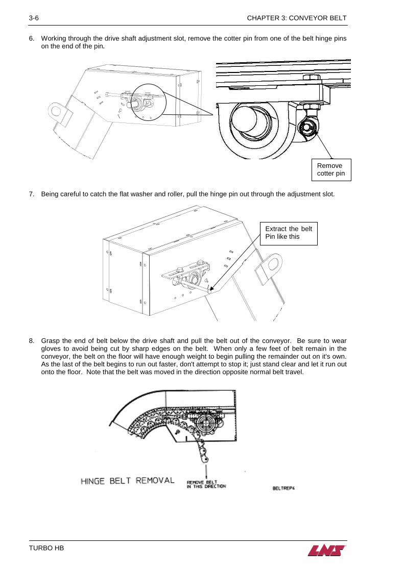
6. Working through the drive shaft adjustment slot, remove the cotter pin from one of the belt hinge pins
on the end of the pin.
7. Being careful to catch the flat washer and roller, pull the hinge pin out through the adjustment slot.
8. Grasp the end of belt below the drive shaft and pull the belt out of the conveyor. Be sure to wear gloves to avoid being cut by sharp edges on the belt. When only a few feet of belt remain in the conveyor, the belt on the floor will have enough weight to begin pulling the remainder out on it's own. As the last of the belt begins to run out faster, don't attempt to stop it; just stand clear and let it run out onto the floor. Note that the belt was moved in the direction opposite normal belt travel.
Remove cotter pin
Extract the belt Pin like this
CHAPTER 3: CONVEYOR BELT 3-7
TURBO HB
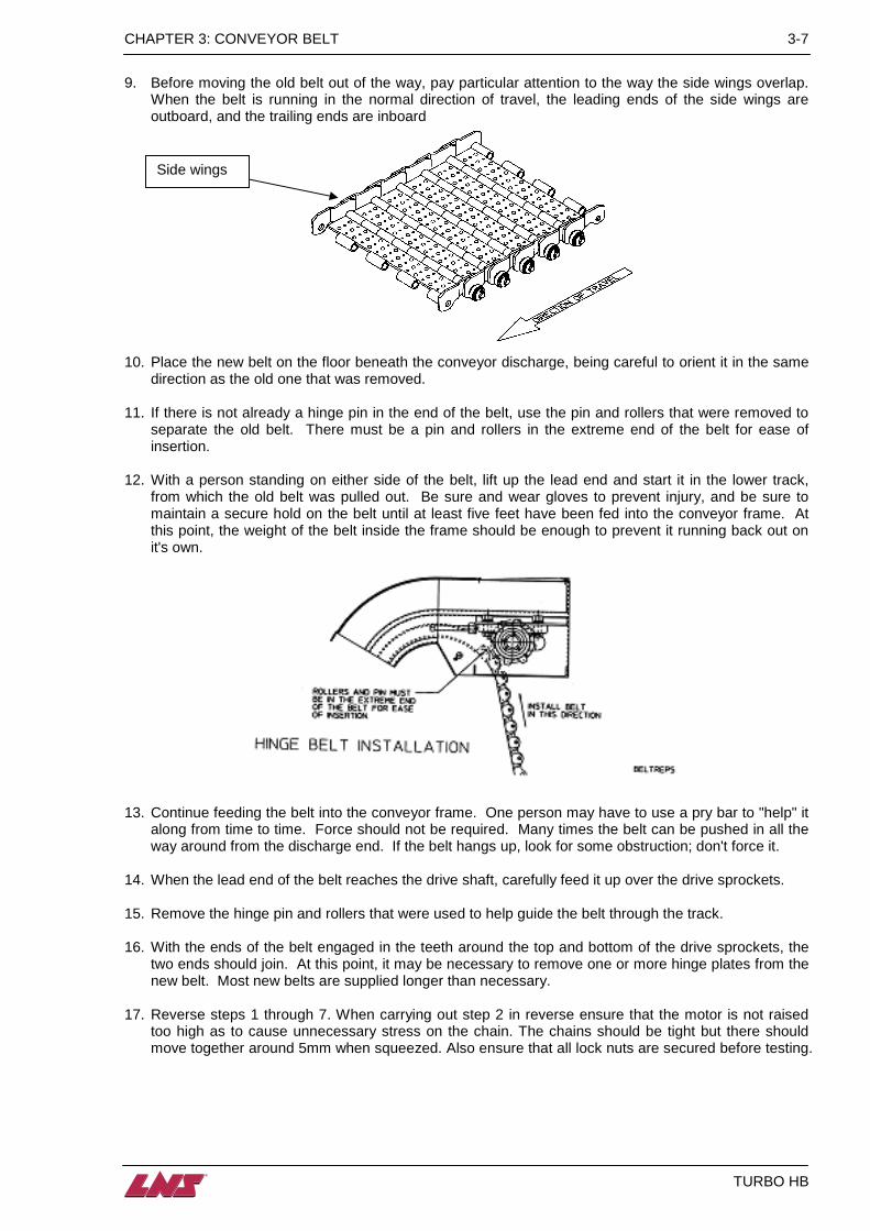
9. Before moving the old belt out of the way, pay particular attention to the way the side wings overlap.
When the belt is running in the normal direction of travel, the leading ends of the side wings are outboard, and the trailing ends are inboard
10. Place the new belt on the floor beneath the conveyor discharge, being careful to orient it in the same
direction as the old one that was removed. 11. If there is not already a hinge pin in the end of the belt, use the pin and rollers that were removed to
separate the old belt. There must be a pin and rollers in the extreme end of the belt for ease of insertion.
12. With a person standing on either side of the belt, lift up the lead end and start it in the lower track,
from which the old belt was pulled out. Be sure and wear gloves to prevent injury, and be sure to maintain a secure hold on the belt until at least five feet have been fed into the conveyor frame. At this point, the weight of the belt inside the frame should be enough to prevent it running back out on it's own.
13. Continue feeding the belt into the conveyor frame. One person may have to use a pry bar to "help" it
along from time to time. Force should not be required. Many times the belt can be pushed in all the way around from the discharge end. If the belt hangs up, look for some obstruction; don't force it.
14. When the lead end of the belt reaches the drive shaft, carefully feed it up over the drive sprockets. 15. Remove the hinge pin and rollers that were used to help guide the belt through the track. 16. With the ends of the belt engaged in the teeth around the top and bottom of the drive sprockets, the
two ends should join. At this point, it may be necessary to remove one or more hinge plates from the new belt. Most new belts are supplied longer than necessary.
17. Reverse steps 1 through 7. When carrying out step 2 in reverse ensure that the motor is not raised
too high as to cause unnecessary stress on the chain. The chains should be tight but there should move together around 5mm when squeezed. Also ensure that all lock nuts are secured before testing.
Side wings

3-8 CHAPTER 3: CONVEYOR BELT
TURBO HB
18. When adjusting belt tension, clamp a pair of vise grip pliers on one of the formed cleats on the belt.
Use the vise grips to "rock" the belt back and forth to feel the slack and drag on the belt. There should not be more than enough slack to allow rocking the drive shaft through 15 degrees of rotation without moving the belt. On a new belt, zero slack is O.K., but if the belt is difficult to move with the vise grips, it's too tight.
19. Visually confirm the belt is located in the center of the frame. Adjust if necessary by loosening the
setscrews in the pillow block bearings and shifting the drive shaft; motor and all; to the left or right as appropriate.
20. Re-connect power and test run the conveyor. The belt should run freely and the only sound should
be a subdued clicking as each hinge plate passes over the drive sprocket.

CHAPTER 3: CONVEYOR BELT 3-9
TURBO HB
3.6. Belt assemblies
Please read the safety instructions provided at the beginning of this manual before carrying out any maintenance on the conveyor.
3.6.1. Standard and Heavy Duty belts
Item No. Description 1 Hex head screw 1 Lock washer 1 Tail disc (on inside of frame) 2 Hinge plate w / cleat 3 Hinge plate 4 Hinge plate / w / wiper cleat 5 Wiper 6 Washer 7 Hex head screw 8 Side wing 9 Roller 10 Washer 11 Link pin 12 Cotter pin
6 7
1 2
5 4
3
12
8
9 10 11
3-10 CHAPTER 3: CONVEYOR BELT
TURBO HB
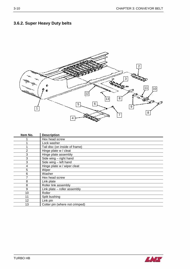
3.6.2. Super Heavy Duty belts
Item No. Description 1 Hex head screw 1 Lock washer 1 Tail disc (on inside of frame) 2 Hinge plate w / cleat 3 Hinge plate assembly 3 Side wing – right hand 3 Side wing – left hand 4 Hinge plate w / wiper cleat 5 Wiper 6 Washer 7 Hex head screw 8 Link plate 8 Roller link assembly 9 Link plate – roller assembly 10 Roller 11 Split bushing 12 Link pin 13 Cotter pin (where not crimped)
1
4
5 6
12
13 8
7
9
8
2
11 10
3

CHAPTER 4: MAINTENANCE 4-1
TURBO HB
CHAPTER 4: MAINTENANCE
4-2 CHAPTER 4: MAINTENANCE
TURBO HB
4.1. Periodic inspection Please read the safety instructions provided at the beginning of this manual before handling the following devices. Switch of the power supply to the system before commencing any maintainance work.
The TURBO HB conveyor has been designed to be low maintenance, however, the following periodic checks should be completed at the recommended service intervals to ensure continued and trouble-free operation.
4.1.1. After first 100 hours • Check belt wipers for excessive wear.
• Inspect conveyor belt parts for excessive wear. If excessive wear is noted, belt should be removed and repaired. (Refer to chapter 3.4 for belt removal instructions.)
• Grease pillow block bearings, using grease gun. Do not grease too often – bearing seals could be damaged.
• Check belt tension.
4.2. Cleaning As with any vehicle, machinery, or device, regular cleaning of your conveyor can only serve to improve its operation and prolong its useful life. For cleaning on the outside, use a soft cloth and a regular detergent, for the inside, use a cloth or a brush. However, make sure that the rollers and parts made of synthetic materials do not come into contact with these products. The use of compressed air for cleaning is not advisable, because particles could become lodged in sensitive areas and impede the proper operation of the conveyor.
At no time should solvents, such as acetone, or diluents be used for cleaning the conveyor. At no time should cleaning products come into contact with electrical components.
4.3. Factors affecting performance The installation is a very important phase that, if neglected, could seriously impede the operation and efficiency of the conveyor system
Level The conveyor must be properly levelled otherwise the flow of coolant through the
conveyor will prevent efficient running such as poor coolant drainage, leakage to the floor or surrounding area, wetter than normal chips and poor interfacing of the conveyor baffles and / or flange to the machine
Alignment If the conveyor is not aligned to the machine and / or tank then the conveyor baffles will not mate to the tank and / or casting properly which will result in an increased volume of chips into the machine tank. The incorrect alignment of the conveyor to the machine and / or tank can also result in safety issues as areas of exposed belt may be seen.
Loose parts In some cases the conveyor may be supplied with additional bolt on or loose parts that are designed to improve the conveyors performance with the particular machine. This can include adjustable conveyor baffles, flanges and levelling feet. If these are not installed the conveyor may not perform efficiently on the machine.

CHAPTER 5: OPTIONS 5-1
TURBO HB
CHAPTER 5: OPTIONS
5-2 CHAPTER 5: OPTIONS
TURBO HB
5.1. Air header Please read the safety instructions provided at the beginning of this manual before handling the following devices. Do not drill holes in the conveyor without consulting LNS beforehand as this will invalidate the warranty as serious damage can occur.
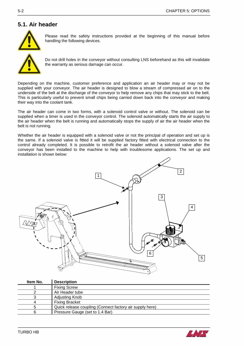
Depending on the machine, customer preference and application an air header may or may not be supplied with your conveyor. The air header is designed to blow a stream of compressed air on to the underside of the belt at the discharge of the conveyor to help remove any chips that may stick to the belt. This is particularly useful to prevent small chips being carried down back into the conveyor and making their way into the coolant tank. The air header can come in two forms, with a solenoid control valve or without. The solenoid can be supplied when a timer is used in the conveyor control. The solenoid automatically starts the air supply to the air header when the belt is running and automatically stops the supply of air the air header when the belt is not running. Whether the air header is equipped with a solenoid valve or not the principal of operation and set up is the same. If a solenoid valve is fitted it will be supplied factory fitted with electrical connection to the control already completed. It is possible to retrofit the air header without a solenoid valve after the conveyor has been installed to the machine to help with troublesome applications. The set up and installation is shown below:
Item No. Description 1 Fixing Screw 2 Air Header tube 3 Adjusting Knob 4 Fixing Bracket 5 Quick release coupling (Connect factory air supply here) 6 Pressure Gauge (set to 1.4 Bar)
1 2
3
4
5 6

CHAPITRE 5: OPTIONS 5-3
TURBO HB
The orientation of the air header is as follows:
For the air usages of the Air header please refer to the chart below:
Air requirement chart (m3/hour) Belt width (mm) 102 203 305 406 508 610 762 914
Air pressure
(Bar)
0.7 2.5 4.9 7.1 9.5 10.9 14.8 19.7 23.4 0.8 2.9 5.3 7.8 10.4 12.1 16.1 21.6 25.8 1.0 3.1 5.8 8.7 11.2 112.9 17.5 23.3 27.9 1.1 3.2 6.1 9.0 12.1 13.9 18.7 25.0 29.9 1.2 3.6 6.6 9.7 12.7 14.8 19.9 26.5 31.6 1.4 3.7 7.0 10.2 13.4 15.5 20.9 27.9 33.3
5-4 CHAPTER 5: OPTIONS
TURBO HB
5.2. Chip stripper bar
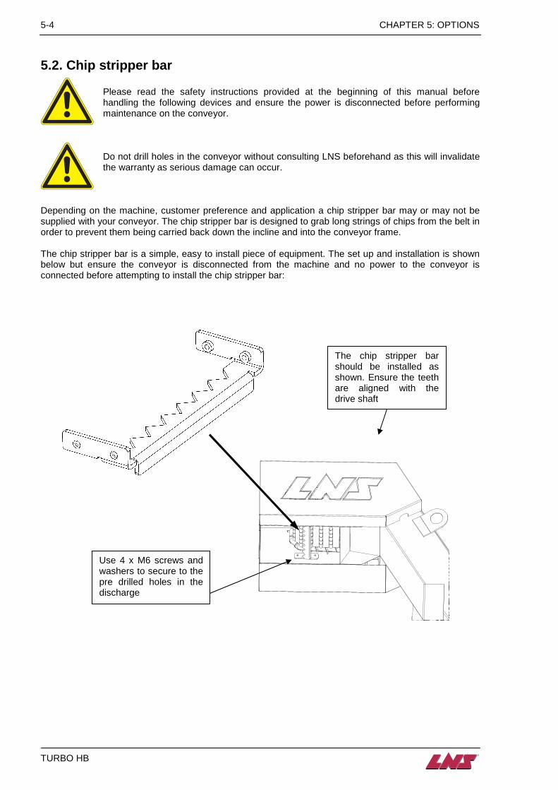
Please read the safety instructions provided at the beginning of this manual before handling the following devices and ensure the power is disconnected before performing maintenance on the conveyor.
Do not drill holes in the conveyor without consulting LNS beforehand as this will invalidate the warranty as serious damage can occur.
Depending on the machine, customer preference and application a chip stripper bar may or may not be supplied with your conveyor. The chip stripper bar is designed to grab long strings of chips from the belt in order to prevent them being carried back down the incline and into the conveyor frame. The chip stripper bar is a simple, easy to install piece of equipment. The set up and installation is shown below but ensure the conveyor is disconnected from the machine and no power to the conveyor is connected before attempting to install the chip stripper bar:
The chip stripper bar should be installed as shown. Ensure the teeth are aligned with the drive shaft
Use 4 x M6 screws and washers to secure to the pre drilled holes in the discharge
CHAPITRE 5: OPTIONS 5-5
TURBO HB
5.3. Spare parts Without the written consent of LNS SA, no addition or modification of the machine or spare parts can be undertaken. LNS SA assumes no responsibility when using spare parts which were not provided by LNS SA.
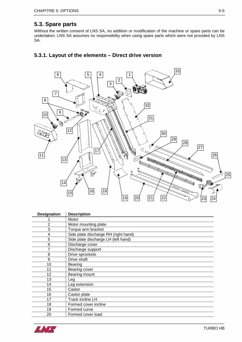
5.3.1. Layout of the elements – Direct drive versio n
Designation Description 1 Motor 2 Motor mounting plate 3 Torque arm bracket 4 Side plate discharge RH (right hand) 5 Side plate discharge LH (left hand) 6 Discharge cover 7 Discharge support 8 Drive sprockets 9 Drive shaft 10 Bearing 11 Bearing cover 12 Bearing mount 13 Leg 14 Leg extension 15 Castor 16 Castor plate 17 Track incline LH 18 Formed cover incline 19 Formed curve 20 Formed cover load
1
7
6
9
11
10
8
12
17
31
13
14
16 15 18
19 20 23 24
25
26
27 28
30 29
32
2 3
21 22
33 4 5

5-6 CHAPTER 5: OPTIONS
TURBO HB
21 Track load LH 22 Track load RH 23 Tail track 24 Track track end cover 25 Tail disc 26 Tail baffle 27 Baffle RG 28 Baffle LH 29 Top cover load 30 Baffle gusset 31 Track incline RG 32 Top cover incline 33 Drive cover
Please note that the appearance of the conveyor may vary and some components may not be present on your conveyor due to application design

CHAPTER 6: APPENDICES 6-1
TURBO HB
CHAPTER 6: APPENDICES
Appendix A : Ordering form A-2 Appendix B : Address LNS A-3
6-2 CHAPTER 6: APPENDICES
TURBO HB
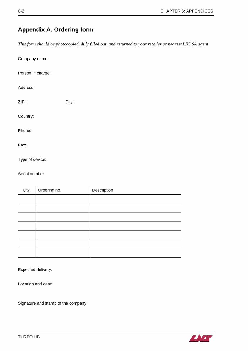
Appendix A: Ordering form
This form should be photocopied, duly filled out, and returned to your retailer or nearest LNS SA agent Company name: Person in charge: Address: ZIP: City: Country: Phone: Fax: Type of device: Serial number:
Qty. Ordering no. Description
Expected delivery: Location and date: Signature and stamp of the company:
CHAPITRE 6: APPENDICES 6-3
TURBO HB
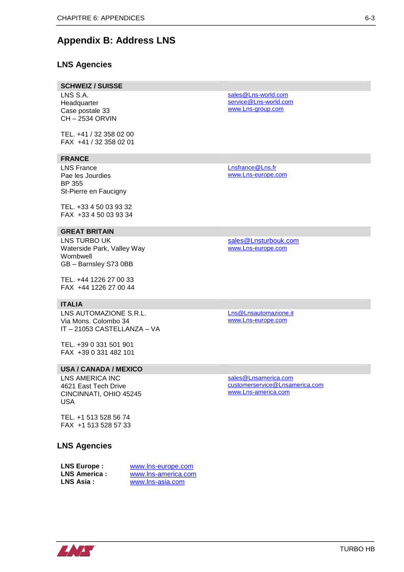
Appendix B: Address LNS
LNS Agencies
SCHWEIZ / SUISSE LNS S.A. Headquarter Case postale 33 CH – 2534 ORVIN
[email protected] [email protected] www.Lns-group.com
TEL. +41 / 32 358 02 00 FAX +41 / 32 358 02 01
FRANCE LNS France Pae les Jourdies BP 355 St-Pierre en Faucigny
[email protected] www.Lns-europe.com
TEL. +33 4 50 03 93 32 FAX +33 4 50 03 93 34
GREAT BRITAIN LNS TURBO UK Waterside Park, Valley Way Wombwell GB – Barnsley S73 0BB
[email protected] www.Lns-europe.com
TEL. +44 1226 27 00 33 FAX +44 1226 27 00 44
ITALIA LNS AUTOMAZIONE S.R.L. Via Mons. Colombo 34 IT – 21053 CASTELLANZA – VA
[email protected] www.Lns-europe.com
TEL. +39 0 331 501 901 FAX +39 0 331 482 101
USA / CANADA / MEXICO LNS AMERICA INC 4621 East Tech Drive CINCINNATI, OHIO 45245 USA
[email protected] [email protected] www.Lns-america.com
TEL. +1 513 528 56 74 FAX +1 513 528 57 33
LNS Agencies
LNS Europe : www.lns-europe.com LNS America : www.lns-america.com LNS Asia : www.lns-asia.com